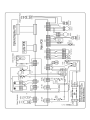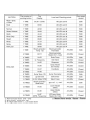
1
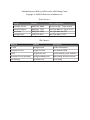
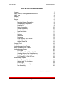
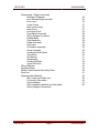
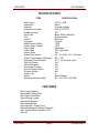
LG TRAINING MANUAL
Dishwasher LDF9810ST
Spring 2008
Published January 2008 by LG Electronics USA Training Center
Copyright © 2008 LG Electronics of Alabama, Inc.
Phone Contacts:
Contact
Number
Hours of Operation
Customer Service
(800) 243-0000
24 hours a day / 7 days a week
Technical Support
(800) 847-7597
7am-7pm Mon-Fri / Sat 8-2 CST
Parts Sales
(888) 393-6484
7am-7pm Mon-Sat CST
Training Center
(256) 774-4051
8am-5pm Mon-Fri CST
Web Contacts:
Web Site
Address
Description
LG USA
www.lgusa.com
Product information
Customer Service
us.lgservice.com
User manuals, FAQs
GCSC
aic.lgservice.com
Service manuals, parts, bulletins
Customer Service Academy
www.lgcsacademy.com
Web training, discussion forum
Live Training
lge.webex.com
Live training
LDF9810ST
DISHWASHER
LDF9810ST DISHWASHER
Contents
Safety Notices, Warnings, and Disclaimers
Safety Tips
Warranty
Specifications
Features
Installation
Electrical Supply Preparation
Water Supply Preparation
Leveling Kit
Drain Connection
Water Connection
Electrical Connection
Final Installation
Control Panel
Options
Indicators
Programs
Dual Intensity Spray Wash
Adding Detergent
Adding Rinse Aid
Program Chart
Test Mode
Troubleshooting Error Codes
Steam Generator Error Codes
Troubleshooting Charts
No Power
Wash Pump / Motor Does Not Run
Washing Results Are Unsatisfactory
Drying Results Are Unsatisfactory
No Power-Off At End Of Cycle
Disassembly / Repair
Lower Cover and Insulation
Cabinet and Tub Insulation
Front Cover
Control Panel Assembly
Fan Assembly
1
3
4
5
6
6
8
9
9
9
10
10
10
11
12
12
12
13
13
14
15
16
17
18
19
20
20
21
22
22
23
24
24
24
24
24
26
Rev 1.0
LDF9810ST
Page 1
080205
DISHWASHER
LDF9810ST
DISHWASHER
Disassembly / Repair (continued)
Detergent Dispenser
Door Springs (Right and Left)
Door Liner
Lower Frame
Drain Hose Holder
Base Cover
Line Noise Filter
Float Switch Assembly
Wiring Diagram (Location)
Cabinet Base
Float Assembly
Steam Generator
Inlet Valve
Air Breaker Assembly
Sump Assembly
Heater and Drain Motor
Vario Motor
Soil Sensor
Reassembly
Cutlery Rail Rack
Upper Rail Rack
Wiring Diagram
Exploded Views
Model / Serial Number Decoding Chart
Parts List
Supplementary Material
Ohm’s Law and Watt’s Law
Conversion Information
Service Bulletin
Drain Installation Method and Information
Wiring Diagram (Oversized)
LDF9810ST
Page 2
26
26
26
27
27
27
28
28
28
28
28
29
29
29
30
30
30
31
31
32
32
33
34
40
41
45
45
46
47
50
DISHWASHER
LDF9810ST
DISHWASHER
IMPORTANT SAFETY NOTICE
The information in this training manual is intended for use by persons possessing an adequate background
in electrical equipment, electronic devices, and mechanical systems. In any attempt to repair a major
appliance, personal injury and property damage can result. The manufacturer or seller maintains no liability
for the interpretation of this information, nor can it assume any liability in conjunction with its use. When
servicing this product, under no circumstances should the original design be modified or altered without
permission from LG Electronics. Unauthorized modifications will not only void the warranty, but may lead to
property damage or user injury. If wires, screws, clips, straps, nuts, or washers used to complete a ground
path are removed for service, they must be returned to their original positions and properly fastened.
CAUTION
To avoid personal injury, disconnect the power before servicing this product. If electrical power is required
for diagnosis or test purposes, disconnect the power immediately after performing the necessary checks.
Also be aware that many household appliances present a weight hazard. At least two people should be
involved in the installation or servicing of such devices. Failure to consider the weight of an appliance could
result in physical injury.
ESD NOTICE
Some of the electronics in appliances are electrostatic discharge (ESD) sensitive. ESD can weaken or
damage the electronics in these appliances in a manner that renders them inoperative or reduces the time
until their next failure. Connect an ESD wrist strap to a ground connection point or unpainted metal in the
appliance. Alternatively, you can touch your finger repeatedly to a ground connection point or unpainted
metal in the appliance. Before removing a replacement part from its package, touch the anti-static bag to a
ground connection point or unpainted metal in the appliance. Handle the electronic control assembly by its
edges only. When repackaging a failed electronic control assembly in an anti-static bag, observe these
same precautions.
REGULATORY INFORMATION
This equipment has been tested and found to comply with the limits for a Class B digital device, pursuant to
Part 15 of the FCC Rules. These limits are designed to provide reasonable protection against harmful
interference when the equipment is operated in a residential installation. This equipment generates, uses,
and can radiate radio frequency energy, and, if not installed and used in accordance with the instruction
manual, may cause harmful interference to radio communications. However, there is no guarantee that
interference will not occur in a particular installation. If this equipment does cause harmful interference to
radio or television reception, which can be determined by turning the equipment off and on, the user is
encouraged to try to correct the interference by one or more of the following measures: Reorient or relocate
the receiving antenna; Increase the separation between the equipment and the receiver; Connect the
equipment to an outlet on a different circuit than that to which the receiver is connected; or consult the
dealer or an experienced radio/TV technician for help.
DISCLAIMER
The information in this training manual was accurate at the time of publication. Every effort has been made
to ensure accuracy. Updates, changes, etc. are available via GCSC and LGCSacademy. The information in
this manual is intended for persons with adequate backgrounds in electronics, mechanical, and electronic
servicing. The manufacturer and seller are not to be held responsible for any liability incurred from its use.
COMPLIANCE
The responsible party for this device’s compliance is LG Electronics Alabama, Inc.; 201 James Record Road,
Huntsville, AL, 35813.
LDF9810ST
Page 3
DISHWASHER
LDF9810ST
DISHWASHER
SAFETY TIPS
•
Disconnect the power before servicing the dishwasher.
•
Reconnect all grounding devices after repairs are complete. This includes
all grounding wires that are attached by screw and ring connector as well
as the power input, whether cordset and outlet or hardwired.
•
Install the dishwasher on a properly fused and grounded dedicated circuit.
•
Steam is HOT! Use care when working with live steam.
•
Do not use the open door as a step or a resting place for dishes, pots and
pans, and other heavy items.
•
Use ONLY detergent and drying agents developed for automatic
dishwashers. DO NOT use detergents made for hand-washing dishes.
•
The dishwasher must be set on firm and even flooring that is at the same
level as the kitchen flooring for the ease of installation and servicing.
•
Do not leave the racks out of the dishwasher. Children may be tempted
top play inside the dishwasher.
•
If the dishwasher is not used for long periods (vacation, seasonal home, et
al.) turn off the water valve.
•
Touch the buttons with your fingers only. Do not poke them with forks,
screwdrivers, or similar items.
•
Do not use the dishwasher to wash items other than dishes and items
used in food preparation. Do not put other items, like aquaria, toilet seats,
bedpans, and other items in it. It is a dishwasher and not an autoclave.
LDF9810ST
Page 4
DISHWASHER
LDF9810ST
DISHWASHER
WARRANTY
LDF9810ST
Page 5
DISHWASHER
LDF9810ST
DISHWASHER
SPECIFICATIONS
ITEM
SPECIFICATION
Rated Input
Installation
Capacity
Dimensions (inches)
Weight (pounds)
Door Color
Tub
Control
Programs
Rated Power (Watts)
Heater Power (Watts)
Upper Rack
Lower Rack
Cutlery Rack
Water Consumption
Power Consumption (kWh/year)
Operating Time (Minutes)
Fan Dry System
Steam Generator
Delay Start Function
Auto-Off Power Switch
Process Monitor
Wash Level
Racks
Operating Pressure (Bar)
120 VAC, 60Ø
Built-in
14 place settings
23⅞ X 25 X 33⅞
128
Black, White, Stainless
Stainless Steel
Electronic
6 Cycles
1,350
1,200
Adjustable
50% Fold Down
Yes
2.6 ~ 6.0 Gals. (10 ~ 26 Liters)
285 ~ 310
101 ~ 135 (normal cycle)
Yes
Yes
Yes
Yes
Yes
5
Nylon Coating
20 ~ 120 (140 ~ 830 kPa)
FEATURES
Ultra Large Capacity
Removable Cutlery Rack
Slim Direct-Drive Motor
Hybrid Drying System
Vario Spray System
Self-Cleaning Filter
Dual Intensity™ Wash Cycle
Steam Washing and Steam Delicate™
Light Tough Buttons and Blue LCD
Auto-Off
LDF9810ST
Page 6
DISHWASHER
LDF9810ST
DISHWASHER
FEATURES, continued
1. Control Panel
2. Door Handle
3. Front Cover
4. Lower Cover
5. Leveling Foot
6. Side Cabinet
7. Base
8. Top Spray Arm
9. Upper Spray Arm
10. Removable Tines
11. Steam Nozzle
12. Lower Spray Arm
13. Dispenser (Detergent / Rinse Aid)
14. Vapor Vent Cover
15. Tub Lamps (IllumiTub™)
16. Cutlery Rack
17. Upper Rack
18. Cutlery Basket
19. Lower Rack
20. Blue LCD Display
21. Power Button
LDF9810ST
Page 7
DISHWASHER
LDF9810ST
DISHWASHER
INSTALLATION
Installation is covered briefly for the servicer who may need to uninstall and
reinstall the dishwasher for repairs. For new installations, please refer to the
installation guide that was supplied with the dishwasher.
•
We recommend a location as close to the sink as possible (but not directly
under it) for easy connection to water and drain lines.
•
The installation must be within 10’ (3 m) of the sink for proper drainage.
•
If the dishwasher is installed in a corner (next to an adjacent wall), there
must be 2” (50 mm) clearance.
•
The floor under the dishwasher should be at the same level as the rest of
the room so the dishwasher can slide in and out easily for service.
Drill a 1½” hole on either side to allow
for the drain hose, water supply hose,
and electrical cable. The opening must
be in an area within 4” (100 mm) of the
back wall and 4” (100 mm) of the floor.
If there is a floor in the cabinet under
the sink, it will be necessary to cut
through it to connect the water, drain,
and electrical cable under the sink.
The dishwasher must be supplied with
120 VAC 60 Hz 1Ø current as indicated
on the rating plate and connected to a
properly fused and grounded dedicated
20-amp circuit.
The wire or water supply can be fed
from either side, and both from the
same side, depending upon source
location.
They must be run in the channels
under the dishwasher, as shown in the
drawing.
LDF9810ST
Page 8
DISHWASHER
LDF9810ST
DISHWASHER
ELECTRICAL SUPPLY PREPATATION
The dishwasher can be hardwired if necessary and if permitted by local code. We
recommend the use of a dishwasher installation kit, available at most hardware
and home supply stored. This kit includes a cordset, a flexible water supply line,
and the elbow connector necessary to connect it. Using a cordset requires an
electric outlet under the sink accessible when the dishwasher is installed. The
cordset makes it easier to disconnect the dishwasher from power while working
on it and makes removal and replacement easier. As stated earlier, installation
requires a properly fused and grounded dedicated circuit.
WATER SUPPLY PREPARATION
The dishwasher may be connected to either hot or cold water. If the hot water
can not maintained below 149° F, the dishwasher must be connected to the cold
water supply. Lay out the water supply line as indicated on page 14 of this
training manual. Use sealing tape or joint compound to avoid leaks.
INSTALLATION
Adjust the legs to the required height
for the dishwasher to slide under the
countertop and be level. Check the
level using a spirit level.
Attach the leveling feet kit to allow for
fine tuning when the dishwasher is
pushed into place.
To complete the installation:
Remove the lower cover.
Make sure the legs are adjusted and
the dishwasher is level.
Lay out the electrical cable, water
supply tube, and drain hose as
shown.
Slide the dishwasher carefully back
into place.
Make the appropriate connections, as
directed below.
LDF9810ST
Page 9
DISHWASHER
LDF9810ST
DISHWASHER
DRAIN CONNECTION
The drain hose must be connected in a manner that meets the local plumbing
code. If the end of the drain hose does not fit the available connector, an adapter
may be obtained from a local hardware or plumbing supplier.
The rubber end can be cut off for the
correct size attachment.
This drawing shows the drain line
installed with a rise in the drain pipe
but no air gap. It can also be with an
air gap installed. Be sure to observe
the clearances listed.
See supplementary drain information on
page 50 of this training manual.
Most garbage disposers have a
dishwasher drain fitting built in to
them. If your installation does not
include a disposer, you can use a
special tail piece with a drain
attachment available at most
hardware and home supply stores.
WATER CONNECTION
Turn off the water supply and connect
the elbow to the inlet valve.
Connect the flexible supply tube to the
elbow.
Use sealing tape to make all
connections.
Make sure the supply line is not kinked.
ELECTRICAL CONNECTION
Use wire
connectors and
replace the
cover on the
junction box.
(12/2 w/ ground,
20-amps)
LDF9810ST
Page 10
DISHWASHER
LDF9810ST
DISHWASHER
FINAL INSTALLATION
1. Turn on the water at the valve under the sink.
2. Turn on the power at the fuse or breaker (or plug in the cordset at the
outlet under the sink.
3. Run the dishwasher through one QUICK cycle to check the operation and
to check for water leaks.
4. Replace the lower cover.
When the door is closed, the top edge with the controls should be under the
countertop.
LDF9810ST
Page 11
DISHWASHER
LDF9810ST
DISHWASHER
CONTROL PANEL
SOAK
Heavily soiled loads, with cooked-on foods
POWER SCRUB Normal soil level, everyday loads
NORMAL
Normal soil level, everyday loads
STEAM DELICATE Washing delicate items, crystal, stemware
QUICK
Light soil level, recently used dishes and cutlery
RINSE ONLY
Rinses only, no washing
OPTIONS
STEAM
RINSE
SPRAY
HALF LOAD
DELAY START
CHILD LOCK
CANCEL
Adds steam to SOAK, POWER SCRUB, and Normal cycles
Pressing cycles through Sanitary, Extra Rinse, or both
Pressing cycles through Strong, Medium, or Soft spray
Pressing chooses either upper or lower rack instead of both
Each press delays the start by one hour up to 24 hours
Press and hold to engage/disengage
Press and hold STEAM DELICATE and NORMAL
INDICATORS
n
o
p
q
Steam option indicator – blinks if selected
Rinse indicator – blinks if selected
Spray indicator – blinks if selected
Half load indicator
r
Child Lock – illuminated when engaged
Rinse Aid – illuminated when refill is required
s
LDF9810ST
Time remaining before cycle ends
Page 12
DISHWASHER
LDF9810ST
DISHWASHER
PROGRAMS
DUAL INTENSITY SPRAY WASH
The spray intensity for the upper lower racks is programmable by the customer.
By selecting SOFT SPRAY for the upper rack and STRONG SPRAY for the
lower rack, you can wash delicate items like stemware on top while washing pots
and pans on the bottom.
1. Press and hold SPRAY to illuminate the indicator.
2. Press SPRAY to set the intensity for the upper rack.
(Strong/Medium/Soft/Off)
3. Press HALF LOAD to confirm the selection for the upper rack.
4. Press SPRAY to set the intensity for the lower rack.
5. Press HALF LOAD to confirm the selection for the lower rack.
6. Select other options.
7. Close the door.
8. The dishwasher will start.
LDF9810ST
Page 13
DISHWASHER
LDF9810ST
DISHWASHER
ADDING DETERGENT
Detergent must be added to the dispenser before the start of every cycle except
RINSE ONLY. The detergent chamber holds 1.4 oz. (40 g) when full. If the
dishes are only moderately dirty, it might be possible to use less detergent.
Press the latch button to open the
detergent chamber.
Add detergent in the proper amount.
(See chart, below.)
Close the cover and be sure the latch
clicks.
If pre-wash cycle is selected (in SOAK
or POWER SCRUB only), add the
appropriate amount of pre-wash
detergent in the recess on the door
cover. When you close the dishwasher
door, the detergent will fall into the tub.
NOTE: Too much detergent can leave
a film on the dishes.
CYCLE
Soak
Power Scrub
Normal
Steam Delicate
Quick
Rinse Only
LDF9810ST
Amt. Detergent
Full (0.35 oz.)
Full (0.35 oz.)
None
None
None
None
Page 14
¾ full (1.05 oz.)
¾ full (1.05 oz.)
½ full (0.7 oz.)
½ full (0.7 oz.)
¼ full (0.3 oz.)
½ full (0.7 oz.)
DISHWASHER
LDF9810ST
DISHWASHER
ADDING RINSE AID
Turn the round cap counterclockwise
and remove it.
Fill the reservoir. It holds 4.8 oz.
(145 ml)
Replace the cap and lock it.
Adjust the rinse-aid setting
as necessary.
The factory setting for rinse aid dispensing is 3. Too little rinse aid contributes to
spotting, streaking, and poor drying performance. Too much rinse aid causes
foaming, which leads to poor washing performance.
How often you refill the dispenser depends upon your washing habits, including
the rinse aid setting, the number of loads per month you wash, and other factors.
The indicator light will illuminate when the level is low at the start of a load.
LDF9810ST
Page 15
DISHWASHER
LDF9810ST
DISHWASHER
PROGRAM CHART
LDF9810ST
Page 16
DISHWASHER
LDF9810ST
DISHWASHER
TEST MODE
LDF9810ST
Page 17
DISHWASHER
LDF9810ST
DISHWASHER
TROUBLESHOOTING ERROR CODES
ERROR CODE
INLET ERROR
Water not to
normal level after
10 minutes’ fill
time
DRAIN ERROR
Not completely
drained after 5
minutes’ drain
time
LEAKAGE
ERROR
Excessive motor
RPM due to
water leakage
POSSIBLE CAUSE
• Water supply valve closed
• Water supply shut off
• Inlet hose kinked
• Water pressure low (below
10 psi)
• Inlet valve defective
• Inlet valve filter clogged
• Hall sensor defective
• Input impeller is bound
• Drain hose kinked or
blocked
• Wiring connection defective
• Drain outlet of sump
blocked
• Drain pump, drain motor, or
drain circuit is defective
• Water leakage in hose
connections
• Water leak from damage
• Sump seal leakage
• Drain hose not high enough
SOLUTION
• Check valve
• Check resistance of valve
(950~1,300Ω)
• Clean the inlet filter
• Check frequency in test
mode (page 13)
• Replace air breaker
• Remove the kink or
blockage
• Check the wiring
connection
• Check the sump for
blockage
• Measure the resistance of
drain motor (20 ~ 40 Ω)
Replace motor or repair
circuit
• Replace hose connections
• Washing pump impeller is
damaged or worn
• Repair damage
• Reseat or replace seal
• Adjust hose to meet
installation requirements
• Replace impeller of
washing pump
• Inlet valve defective
• Replace inlet valve
• Main board defective
• Replace main board
FILL ERROR
Excess water
supplied and
drain pump runs
automatically
LDF9810ST
Page 18
DISHWASHER
LDF9810ST
ERROR CODE
DISHWASHER
POSSIBLE CAUSE
• Inlet water temperature too
hot (over 194° F or 90 °C)
• Wiring connection defective
THERMAL
ERROR
• Thermistor defective
Water not to
normal level after
10 minutes’ fill
time
• Wiring connection loose
• Wash pump impeller locked
LOCK ERROR
• Wash motor rotor is locked
• Blade is locked
Motor is locked
or hall sensor is
defective.
SOLUTION
• Check water temperature
using TEST MODE (See
Page 13.)
If temperature is
displayed, adjust water
temp. to 120° F (40° C).
If temp. is not displayed,
check wiring connections
and resistance of the
thermistor (11~14 KΩ @
77° F or 25° C).
• Check wiring connections
• Check wash pump for
blockage
• Replace wash motor
• Check the sump for
blockage
• Replace the main board
STEAM GENERATOR ERROR CODES
ERROR CODE
CONDITION
SOLUTION
00 : EO
Normal
00 : E1
Steam generator
temperature is too high
(over 239° F or 115° C)
Check water level sensor
and thermistor
00 : E2
Water level sensor failure
Check water level sensor
and connection
00 : E3
Water level too low
Check water level sensor
and inlet valve
00 : E4
Steam generator
temperature is too low
(under 158° F or 70° C)
Check heater and
thermistor
00 : E5
Normal
LDF9810ST
Page 19
DISHWASHER
LDF9810ST
DISHWASHER
TROUBLESHOOTING
NO POWER WHEN THE POWER BUTTON IS PRESSED
LDF9810ST
Page 20
DISHWASHER
LDF9810ST
DISHWASHER
WASH PUMP / MOTOR DOES NOT RUN
LDF9810ST
Page 21
DISHWASHER
LDF9810ST
DISHWASHER
WASHING RESULTS ARE UNSATISFACTORY
DRYING RESULTS ARE UNSATISFACTORY
LDF9810ST
Page 22
DISHWASHER
LDF9810ST
DISHWASHER
POWER BUTTON NOT AUTOMATICALLY OFF AFTER OPERATION
LDF9810ST
Page 23
DISHWASHER
LDF9810ST
DISHWASHER
DISASSEMBLY / REPAIR
Before disassembling the dishwasher:
•
Unplug the dishwasher or turn off the breaker (or fuse)
Disconnect the wire if the dishwasher is hard-wired.
•
Turn of the water supply
•
Remove all dishes and racks
•
Disconnect the water supply line to avoid hose damage
•
Have some towels ready to catch the spillage from water left in the
dishwasher and to keep the floor safe.
LOWER COVER AND INSULATION
Remove the two screws in the
lower cover.
Remove the insulation.
Disconnect the water supply hose and
the electric cable if you are removing
the dishwasher for service.
CABINET AND TUB INSULATION
Right Cabinet –
Remove two screws at the front and
three screws at the rear.
Left Cabinet –
Remove two screws at the front and
three screws at the rear.
Insulation –
Remove the insulation blanket
carefully by lifting straight up.
LDF9810ST
Page 24
DISHWASHER
LDF9810ST
DISHWASHER
DOOR ASSEMBLY
FRONT COVER
Open the door.
Remove 12 screws (stainless steel).
CONTROL PANEL ASSEMBLY
Remove 2 screws (stainless steel).
Remove the wire connections.
(Do not reverse at reassembly!)
Remove the latch assembly.
Remove the front display.
Remove 8 screws to take out the
controller (main board).
Reassembly is the reverse order of
disassembly. Be careful to avoid
reversing the connectors.
LDF9810ST
Page 25
DISHWASHER
LDF9810ST
DISHWASHER
DOOR ASSEMBLY, continued
FAN ASSEMBLY
Remove the front cover.
(See page 25.)
Remove 4 screws and a ground screw
for the door bracket.
Remove the wire connections from the
fan.
Remove the air duct.
Unscrew the inner cover to remove the
fan assembly.
DETERGENT DISPENSER
Remove the wire connections.
Remove the 2 brackets (6 screws).
Use a screwdriver to pry the flange up
to release the dispenser (above left.)
DOOR SPRING (Right and Left)
Pull the spring upward and take it off
the hinge bracket.
Take the spring off the hinge.
DOOR LINER
Open the door.
Pull the door liner upward off the hinge
supporter.
LDF9810ST
Page 26
DISHWASHER
LDF9810ST
DISHWASHER
LOWER FRAME
Press the holder hooks as shown.
Remove the 4 screws.
Turn the dishwasher upside down.
DRAIN HOSE HOLDER
Press the holder hook as shown.
Pull the drain hose and remove the
drain hose holder.
BASE COVER
Remove 2 screws.
Lift the base cover out of the base.
LDF9810ST
Page 27
DISHWASHER
LDF9810ST
DISHWASHER
LINE NOISE FILTER
Disconnect both connectors of the line
noise filter.
FLOAT SWITCH ASSEMBLY
Remove the connections from the float
assembly micro switches. Mark them to
ensure you can reconnect them
correctly after repairs.
WIRING DIAGRAM
The wiring diagram is attached to the
back of the lower cover.
CABINET BASE
Remove 8 screws around the base.
Lift the base upward off the
dishwasher.
FLOAT ASSEMBLY
Press the hook to separate the float
assembly.
Pull the float assembly free.
LDF9810ST
Page 28
DISHWASHER
LDF9810ST
DISHWASHER
STEAM GENERATOR
Squeeze the hose clamps and remove
the 3 hoses from the steam generator.
Remove 2 screws to take out the
steam generator.
NOTE: Be careful in case the steam
generator is still hot or has hot water
in it.
The steam generator is sold as an
assembly. The individual parts (heater,
thermistor, and sensor) are not
repairable or replaceable.
INLET VALVE
Disconnect the water supply line.
Remove the electrical ground wire.
Remove 2 screws that hold the valve to
the base and take out the valve.
AIR BREAKER ASSEMBLY
Disconnect three hoses from the air
breaker assembly.
Unscrew the cover on the inside of the
dishwasher.
Be sure not to lose the gasket (O-ring)
that fits between the outside of the tub
and the air breaker assembly.
LDF9810ST
Page 29
DISHWASHER
LDF9810ST
DISHWASHER
SUMP ASSEMBLY
Remove the wiring connections,
including the ground wires attached
by screws.
Remove the hose connections.
Lift the sump assembly out of the base
of the dishwasher.
Remove the 2 screws and sump holder
clips. Be careful not to let the sump
assembly fall into the tub.
Press the hooks gently toward the
center of the sump assembly and lower
the sump assembly into the tub while
supporting it with one hand.
HEATER and DRAIN MOTOR
Loosen the nut on the heater retainer
to the end of the shaft and wiggle the
heater out of the sump.
Remove 3 screws and detach the drain
pump from the sump.
VARIO MOTOR
Remove 2 screws that attach the vario
motor to the sump.
Remove the vario motor and the micro
switch.
LDF9810ST
Page 30
DISHWASHER
LDF9810ST
DISHWASHER
SOIL SENSOR
Lift the retaining clips and pull the soil
sensor (turbidity sensor) from the
sump.
REASSEMBLY
When reassembling the sump. be
careful to avoid kinking or damaging
the small seals and gaskets inside it.
(See page 39 in the exploded view.)
LDF9810ST
Page 31
DISHWASHER
LDF9810ST
DISHWASHER
CUTLERY RACK RAIL
Insert a screwdriver in the gap behind
the rail at the back end and pry the end
cap off. It is easily broken, so have a
replacement available.
UPPER RACK RAIL
Pull the upper rack out until it stops.
Squeeze the tab of the stopper and pull
the stopper out. Be careful the upper
rack does not fall out of the rail while
you do this.
Pull the upper rack out of the slides.
LDF9810ST
Page 32
DISHWASHER
LDF9810ST
DISHWASHER
WIRING DIAGRAM
LDF9810ST
Page 33
DISHWASHER
LDF9810ST
DISHWASHER
EXPLODED VIEWS
LDF9810ST
Page 34
DISHWASHER
LDF9810ST
DISHWASHER
EXPLODED VIEWS, continued
LDF9810ST
Page 35
DISHWASHER
LDF9810ST
DISHWASHER
EXPLODED VIEWS, continued
LDF9810ST
Page 36
DISHWASHER
LDF9810ST
DISHWASHER
EXPLODED VIEWS, continued
LDF9810ST
Page 37
DISHWASHER
LDF9810ST
DISHWASHER
EXPLODED VIEWS, continued
LDF9810ST
Page 38
DISHWASHER
LDF9810ST
DISHWASHER
EXPLODED VIEWS, continued
LDF9810ST
Page 39
DISHWASHER
LDF9810ST
DISHWASHER
SERIAL NUMBERS
[Example] 801KW3400251
801 KW 34
00251
Production Number
[Internal code]
Made in Korea
Manufactured January 2008
New Serial Code (ETA Mid 2008)
12345 KR 406 YP 000002 + Options
Sequential number
Internal code
Year and month of production (YMM)
Production site (2 Letters)
Model ID
LDF9810ST
Page 40
DISHWASHER
LDF9810ST
DISHWASHER
PARTS LIST
Loc.
*001
*002
*003
*005
A003
A005
A006
A007
A008
A010
A020
A040
A050
A060
A070
A073
A074
A101
A102
A103
A110
A120
A130
A140
A141
A142
A144
A145
A146
A147
A148
A149
A150
A151
A155
A156
A157
A158
A159
A160
Part Number
AFN31666719
3890DZ3015A
MFL37554802
5001DD4001A
ACV34326901
4810DD4002B
4980ED2015A
4980ED2014A
4980ED2018B
3090ED1001F
3091DD1001F
3551DD2001E
5249DD1002Q
5249DD1001A
4975DD1002A
1WZZDD3001A
4370ED3007A
MEB38945801
MEB38945901
MEB38946001
5005DD1001B
EAD38156501
AEM30700301
AHB33839701
MGR38994701
4581DD3003B
3750DD2003A
4930ED3003D
4930ED3004D
4930DD3006A
3750DD1001A
3750DD1002A
AHB33839501
MGR38994101
AEC32598702
AEC32598602
4930DD3003B
4930DD3005A
3750DD2002A
6201EC1006A
LDF9810ST
Description
Qty.
Owner's Manual
Box, Carton
Manual, Service
Accessory Assembly
Damper (Insulation)
Bracket, Top
Supporter, Holder
Supporter, Holder
Supporter, Holder
Cabinet
Cabinet Assembly
Cover Assembly, Lower
Nozzle Assembly, Lower
Nozzle Assembly, Upper
Guide Assembly, Upper Nozzle
Washer, Common
Shaft, Nozzle
Handle (Rack)
Handle (Rack)
Handle (Rack)
Basket Assembly, Spoon
Harness, Multi
Hose Assembly, Drain
Rack Assembly, Lower
Rack
Roller Assembly
Rack
Holder
Holder
Holder
Rack
Rack
Rack Assembly, Upper
Rack
Guide Assembly, Right
Guide Assembly, Left
Holder
Holder
Rack
Filter Assembly, AC Line
Page 41
1
1
0
1
1
2
1
1
1
1
1
1
1
1
1
1
1
1
1
1
1
1
1
1
1
8
2
1
1
1
1
1
1
1
1
1
2
2
2
1
DISHWASHER
LDF9810ST
Loc.
A165
A170
A171
A172
A173
A174
A175
A301
E010
F001
F004
F005
F011
F013
F014
F022
F040
F041
F042
F043
F045
F050
F060
F101
F110
F118
F121
F122
F123
F132
F141
F142
F143
F144
F171
F174
F191
F192
F210
F230
F240
F300
K001
DISHWASHER
Description
MGR38994201
AHB33839401
MJS38945601
MGR38994001
AEC33858601
AEC33858701
MEG38945701
1SBF0402418
4830ED4001A
3211DD1001A
5249DD2001A
4370ED3006A
4970ED4004G
4933DD3001A
4810ED4004A
6501DD2001A
4975ED1005B
AEM34434401
5214DD3003A
MEJ39603301
3550DD2001A
4020FD3641C
4986DD3001A
3920DD3002A
4581DD3001A
4620ED3003A
MJB32864101
MGT32863801
AEN32597901
3920DD3005A
4775DD2001A
4775DD2002A
4775ED3004A
4775ED3003A
4026DD3001A
4810DD1001A
MEA36937101
4974DD3001A
4581DD3001B
4810DD4005A
6913ER4001B
AGB33696301
4924FD2123E
LDF9810ST
Part Number
Qty.
Rack, Tine
Rack Assembly, Cutlery
Tray, Cutlery
Rack, Cutlery
Guide As’mbly, Cutlery Rack, Right
Guide As’mbly, Cutlery Rack, Left
Holder, Cutlery Rack
Screw, Taptite, Latch Lock
Bush
Frame Assembly
Nozzle Assembly, Top
Shaft, Nozzle, Top
Spring, Hinge
Connector Assembly
Bracket, Hinge
Sensor Assembly
Guide Assembly
Hose Assembly, Connector
Hose, Connector
Hose, Connector
Cover, Protect
Nut, Common
Gasket
Packing
Roller Assembly, Third Rack, Left
Stopper, Roller
Stopper, Roller, Upper Rack Rail
Rail, Upper Rack
Housing Assembly, Bearing
Packing, Tub
Hinge Assembly, Door
Hinge Assembly, Door
Hinge Assembly, Tub
Hinge Assembly, Tub
Locker, Lock
Bracket, Hinge
Guide, Water
Guide, Nozzle
Roller Assembly, Third Rack, Right
Bracket, Tub
Lamp, Incandescent
Steam Nozzle Assembly
Dispenser
Page 42
1
1
2
1
1
1
2
1
2
1
1
1
2
2
2
1
1
1
1
1
1
1
1
1
2
1
1
2
2
1
1
1
1
1
1
1
1
1
2
2
2
1
1
DISHWASHER
LDF9810ST
Loc.
K002
K005
K010
K030
K100
K101
K110
K121
K122
K124
K200
K207
K215
K220
K251
K252
K253
K260
K301
K302
K303
K304
M001
M005
M006
M007
M025
M026
M027
M028
M031
M034
M035
M036
M038
M050
M060
M081
M086
M087
M088
M090
M110
DISHWASHER
Description
4810FD3805A
AED33189701
3550ED0001J
3551DD1003K
4937DD1001B
AGM34891601
5835ED2002D
5834FD3666A
3550ED3011A
MJZ36939301
AGL33667101
MCK40133201
MCK40228201
AFZ34353901
EBR38144401
EBR38145001
EBR38145201
4027ED3002D
4000FD4268A
1SZZED3001A
1SZZED3002A
1SZZED3003A
4930DD3002A
MDS37912401
AJH31248603
AJH32598001
MJX32862501
4681ED3001B
3W40025C
MBJ32856401
3920ED4009B
5832DD4001A
MFZ32863101
4930DD3008A
4930DD3012A
4681EA2002D
4681ED1004A
5301DD1001A
3W40025P
6501ED2002F
3740ED3003A
4769DD2001B
ADQ32598202
LDF9810ST
Part Number
Qty.
Bracket Assembly
Handle Assembly
Cover, Front
Cover Assembly, Front
Door Liner, Casing/Dispenser/Vent
Assembly (door liner, insul, gasket)
Impeller Casing Assembly
Impeller Gasket
Cover, Blower
Vent
Panel Assembly, Control
Cover, Guide
Cover, Guide
Name Plate Assembly
PCB Assembly, Main
PCB Assembly, Display
PCB Assembly, Display
Locker Assembly
Screw, Custom, Door Liner Hinge
Screw, Custom, Door Liner, Cover
Screw, Custom, Door Latch
Screw, Custom, Front Cover
Holder
Sump Gasket
Sump Assembly
Sump Assembly
Valve, Check
Vario Motor
Switch, Micro
Cam, Switch
Vario Motor Packing
Blade
Packing
Holder
Holder
Motor Assembly, AC, Drain Pump
Motor Assembly, DC, Washer
Heater Assembly
Switch, Micro
Sensor Assembly, Turbidity
Cover
Float Assembly
Filter Assembly, Mesh
Page 43
2
1
1
1
1
1
1
1
1
1
1
7
5
1
1
1
1
1
4
6
2
6
1
1
1
1
1
1
1
1
1
1
1
2
1
1
1
1
2
1
1
1
1
DISHWASHER
LDF9810ST
Loc.
M120
M130
M210
M220
M260
M261
M262
M270
M300
M301
M302
M303
M304
M305
M500
DISHWASHER
Description
ABQ32598101
5911ED3003A
AJU33450701
5220ED4004A
MAM34326301
ACQ31707201
3110DD3002A
4778DD3001A
5001DD2001C
4W51229F
1SZZED3005A
1SZZED3006A
1SZZFA4305A
4W51194D
ADZ32992801
LDF9810ST
Part Number
Pump Case Assembly
Impeller Assembly
Valve Assembly, Inlet
Valve, Check
Base, Cabinet
Cover Assembly, Base
Case
Leg
Accessory Assembly
Screw, Customized
Screw, Customized
Screw, Customized
Screw, Customized
Screw, Customized
Steam Generator Assembly
Page 44
Qty.
1
1
1
1
1
1
1
4
1
4
8
1
3
4
1
DISHWASHER
LDF9810ST
DISHWASHER
OHM’S LAW and WATT’S LAW
P = WATTS
I = AMPERES
Watts = Volts x Ohms
Watts = Amperes2 x Ohms
Watts = Volts x Amperes
Amperes = Volts / Ohms
Amperes = Watts / Volts
Amperes =
2
I •R
2
E /R
2
P• R
E•I E/R
P/E
P I
WATTS
CURRENT
VOLTS
OHMS
P/R
P/I
E R
P/I
2
E /P
2
I•R E/I
E = VOLTS
R = OHMS
Volts =
Volts = Watts / Amperes
Volts = Amperes x Ohms
Ohms = Volts / Amperes
Ohms = Volts2 / Amperes
Ohms = Watts / Amperes2
LDF9810ST
Page 45
DISHWASHER
LDF9810ST
DISHWASHER
CONVERSION INFORMATION
FORMULAE
°F = (9/5) °C + 32
°C = (5/9) x (°F – 32)
ml X 30 = ounces
LDF9810ST
Page 46
DISHWASHER
LDF9810ST
DISHWASHER
SERVICE BULLETINS
The bulletins included here were current and accurate at the time this manual
was printed. The servicer is encouraged to check GCSC regularly for new and
updated bulletins.
LDF9810ST
Page 47
DISHWASHER
LDF9810ST
LDF9810ST
DISHWASHER
Page 48
DISHWASHER
LDF9810ST
LDF9810ST
DISHWASHER
Page 49
DISHWASHER
LDF9810ST
DISHWASHER
SERVICE BULLETIN
DRAIN INSTALLATION
LDF9810ST
Page 50
DISHWASHER
LDF9810ST
DISHWASHER
SERVICE BULLETIN
LDF9810ST
Page 51
DISHWASHER
LDF9810ST
DISHWASHER
SERVICE BULLETIN
LDF9810ST
Page 52
DISHWASHER
LDF9810ST
DISHWASHER
SERVICE BULLETIN
LDF9810ST
Page 53
DISHWASHER
LDF9810ST
DISHWASHER
SERVICE BULLETIN
LDF9810ST
Page 54
DISHWASHER
LDF9810ST
DISHWASHER
SERVICE BULLETIN
LDF9810ST
Page 55
DISHWASHER
LDF9810ST
DISHWASHER
SERVICE BULLETIN
LDF9810ST
Page 56
DISHWASHER
LDF9810ST
DISHWASHER
SERVICE BULLETIN
LDF9810ST
Page 57
DISHWASHER
LDF9810ST
DISHWASHER
SERVICE BULLETIN
LDF9810ST
Page 58
DISHWASHER
LDF9810ST
DISHWASHER
SERVICE BULLETIN
LDF9810ST
Page 59
DISHWASHER
LDF9810ST
DISHWASHER
NOTES
LDF9810ST
Page 60
DISHWASHER
Dishwasher - Spring 2008