1
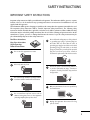
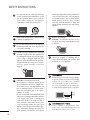
20/23LS7DC, 26/32LC7DC, 42/50PC5DC, 60PC1DC
Integrated TVs
PUBLIC DISPLAY MODE SETUP
How to use the TLL-1100A TV-Link Loader
to copy and clone a Master TV setup is
provided in the operation manual supplied
with the TV-Link Loader
Note: Prior to cloning the Public Display Mode
Setup, be sure to set up all the other TV features
that should be included in the master TV setup.
This includes channel adding-deleting, video and
audio menu setups and other TV features that are
clonable. Refer to the TV installation guide for
specific details.
P/NO : MFL34797021 (0707-REV01)
Printed in Korea
WARNING / CAUTION
WARNING / CAUTION
To prevent fire or shock hazards, do not expose
this product to rain or moisture.
TO REDUCE THE RISK OF ELECTRIC SHOCK
DO NOT REMOVE COVER (OR BACK). NO
USER SERVICEABLE PARTS INSIDE. REFER TO
QUALIFIED SERVICE PERSONNEL.
The lightning flash with arrowhead
symbol, within an equilateral triangle,
is intended to alert the user to the
presence of uninsulated “dangerous voltage”
within the product’s enclosure that may be of
sufficient magnitude to constitute a risk of electric
shock to persons.
The exclamation point within an equilateral
triangle is intended to alert the user to
the presence of important operating and maintenance (servicing) instructions in the literature
accompanying the appliance.
WARNING/CAUTION
TO REDUCE THE RISK OF FIRE AND ELECTRIC
SHOCK, DO NOT EXPOSE THIS PRODUCT TO
RAIN OR MOISTURE.
NOTE TO CABLE/TV INSTALLER
This reminder is provided to call the CATV system
installer’s attention to Article 820-40 of the National
Electric Code (U.S.A.). The code provides guidelines for
proper grounding and, in particular, specifies that the
cable ground shall be connected to the grounding system of the building, as close to the point of the cable
entry as practical.
2
FCC NOTICE
Class B digital device
This equipment has been tested and found to comply with the limits for a Class B digital device, pursuant to Part 15 of the FCC Rules. These limits are
designed to provide reasonable protection against
harmful interference in a residential installation. This
equipment generates, uses and can radiate radio frequency energy and, if not installed and used in
accordance with the instructions, may cause harmful
interference to radio communications. However,
there is no guarantee that interference will not
occur in a particular installation. If this equipment
does cause harmful interference to radio or television reception, which can be determined by turning
the equipment off and on, the user is encouraged to
try to correct the interference by one or more of
the following measures:
- Reorient or relocate the receiving antenna.
- Increase the separation between the equipment
and receiver.
- Connect the equipment to an outlet on a circuit
different from that to which the receiver is connected.
- Consult the dealer or an experienced radio/TV
technician for help.
Any changes or modifications not expressly
approved by the party responsible for compliance
could void the user’s authority to operate the
equipment.
CAUTION
Do not attempt to modify this product in any way
without written authorization from LG Electronics.
Unauthorized modification could void the user’s
authority to operate this product
SAFETY INSTRUCTIONS
IMPORTANT SAFETY INSTRUCTIONS
Read these instructions.
Keep these instructions.
Heed all warnings.
Follow all instructions.
al
nu
a
rM
ne
Ow
al
nu ual
al
n
a
nu
al
r M Ma
a
nu
ne e r
rM
a
ne
rM
Ow Own
ne
Ow
Ow
Important safety instructions shall be provided with each apparatus. This information shall be given in a separate
booklet or sheet, or be located before any operating instructions in an instruction for installation for use and
supplied with the apparatus.
This information shall be given in a language acceptable to the country where the apparatus is intended to be used.
The important safety instructions shall be entitled “Important Safety Instructions”. The following safety
instructions shall be included where applicable, and, when used, shall be verbatim as follows. Additional safety
information may be included by adding statements after the end of the following safety instruction list. At the
manufacturer’s option, a picture or drawing that illustrates the intent of a specific safety instruction may be
placed immediately adjacent to that safety instruction:
Do not use this apparatus near water.
2
Clean only with dry cloth.
Do not defeat the safety purpose of the polarized
or grounding-type plug. A polarized plug has
two blades with one wider than the other. A
grounding type plug has two blades and a third
grounding prong, The wide blade or the third
prong are provided for your safety. If the provided
plug does not fit into your outlet, consult an
electrician for replacement of the obsolete outlet.
6
Protect the power cord from being walked on
or pinched particularly at plugs, convenience
receptacles, and the point where they exit from
the apparatus.
7
Only use attachments/accessories specified by
the manufacturer.
8
Unplug this apparatus when unused for long
periods of time.
r
ne
Ow
1
5
Ma
al
nu
r
ne
Ow
a
M
nu
al
r
ne
Ow
a
M
l
a
nu
r
ne
Ow
a
M
nu
al
r
ne
Ow
a
al
M
nu
r
ne
a
M
Ow
l
a
nu
3
n
Ow
Do not install near any heat sources such as
radiators, heat registers, stoves, or other apparatus
(including amplifiers)that produce heat.
er
ula
una
an
M
l
4
Do not block any ventilation openings. Install in
accordance with the manufacturer’s instructions.
3
SAFETY INSTRUCTIONS
Use only with the cart, stand, tripod, bracket,
or table specified by the manufacturer, or sold
with the apparatus. When a cart is used, use
caution when moving the cart/apparatus
combination to avoid injury from tip-over.
with an exact replacement part by an authorized
servicer. Protect the power cord from physical
or mechanical abuse, such as being twisted,
kinked, pinched, closed in a door, or walked
upon. Pay particular attention to plugs, wall
outlets, and the point where the cord exits the
appliance.
ne
Ow
a
rM
al
nu
9
ne
Ow
a
rM
al
nu
ne
Ow
a
rM
al
nu
ne
Ow
a
rM
al
nu
10
Never touch this apparatus or antenna during
a thunder or lighting storm.
11
Do not allow a impact shock or any objects to
fall into the product, and do not drop onto the
screen with something.
12
Refer all servicing to qualified service personnel.
Servicing is required when the apparatus has
been damaged in any way, such as power-supply
cord or plug is damaged, liquid has been
spilled or objects have fallen into the apparatus,
the apparatus has exposed to rain or moisture,
does not operate normally, or has been
dropped.
14
15
16
13
4
CAUTION concerning the Power Cord :
Most appliances recommend they be placed
upon a dedicated circuit; that is, a single outlet
circuit which powers only that appliance and
has no additional outlets or branch circuits.
Check the specification page of this owner's
manual to be certain.
Do not overload wall outlets. Overloaded wall
outlets, loose or damaged wall outlets, extension
cords, frayed power cords, or damaged or
cracked wire insulation are dangerous. Any of
these conditions could result in electric shock
or fire. Periodically examine the cord of your
appliance, and if its appearance indicates damage or deterioration, unplug it, discontinue use
of the appliance, and have the cord replaced
Outdoor use marking :
WARNING - To reduce the risk of fire or electric shock, do not expose this appliance to rain
or moisture.
Wet Location Marking : Apparatus shall not be
exposed to dripping or splashing and no
objects filled with liquids, such as vases, shall
be placed on or over apparatus.
GROUNDING
Ensure that you connect the earth ground wire
to prevent possible electric shock. If grounding
methods are not possible, have a qualified
electrician install a separate circuit breaker.
Do not try to ground the unit by connecting it
to telephone wires, lightening rods, or gas pipes.
Power
Supply
Short-circuit
Breaker
17
DISCONNECTING POWER:
Power is supplied to the Link-Loader if the
power cord is connected. Unplug power cord
from AC power outlet to remove power.
CONTENTS
WARNING / CAUTION . . . . . . . . . . . . . . . . . . . . . . . . . . . . . . . . . . . . . . . . . . . . . . . . . . 2
SAFETY INSTRUCTIONS . . . . . . . . . . . . . . . . . . . . . . . . . . . . . . . . . . . . . . . . . . . . . . . . 3
INSTALLATION MENU
Entering the Installation Menu
...............................................
6
Public Display Settings . . . . . . . . . . . . . . . . . . . . . . . . . . . . . . . . . . . . . . . . . . . . . . . . . . . . . . . . . . . .7
TV Link-Loader
......................................................................
Password Change
.................................................................
9
10
TV Link-Loader Key Functions . . . . . . . . . . . . . . . . . . . . . . . . . . . . . . . . . . . . . . . . . . . . . . . . 11
5
INSTALLATION MENU
ENTERING THE INSTALLATION MENU
INSTALLATION MENU
The feature set up available on this LG commercial TV which features ‘TV link’ are shown on the ‘Installation
Menu ’. This simple menu is designed to make it easy and efficient for the system integrator to install and set up
the institution’s communications system.
Public Display Mode controls operation and functionality of the TV. Once set up, these settings are clonable; they
can be copied and transferred to another identical TV. See the TV Link-Loader section for cloning details.
Accessing the Installation Menu with
the Menu Button
1
With an LG installer remote, press and hold down the
Menu key for five seconds. The TV screen will show
the Enter Password display.
EZ Scan
Manual Scan
Channel Edit
DTV Signal
Input Source
Input Label
2
Key in “1-1-0-5” and press E N T E R button. This is
the initial password. The password can be changed as
required.
Set ID
Enter Password
Accessing the Public Display Mode Menu
3
4
Use the D or E button to select the Public Display
Settings option and press the G button.
Once in the Public Display Settings menu, use the D
E F G button to select and adjust the menu options
to your requirements. If you want Public Display mode
to be enabled, select ‘Yes’ for that option.
Accessing the Public Display Mode
Menu with the Mode Button
1
6
Press and hold the M O D E button for more that 3
seconds. The TV will automatically display the
Installation Menu after about 5-7 seconds.
*
*
*
*
Installation Menu (V1.0)
Public Display Settings
G
TV Link-Loader
G
Password Change
G
Set ID setup
G
PUBLIC DISPLAY SETUP
Set item to act TV with standalone.
2
Use the D or E button to select desired menu options.
Use the F or G button to adjust the menu option settings.
Installation Menu (V1.0)
Public Display Settings
G
TV Link-Loader
G
Password Change
G
Set ID setup
G
INSTALLATION MENU
1
Public Display Settings
Public Display Mode Menu Items
Public Display Mode
No
Start Channel
No
Ch. Type
DTV
Major
12
Minor
0 1 . Public Display Mode
If ‘Public Display Mode is set to Yes (Enabled), all functions of Public Display
Settings are active. If ‘Public Display Mode is set to No (Disabled), all functions
of Public Display mode are not active.
0
Maximum Volume
100
Start Volume
Level
Power Management
Setting
02. Start Channel
This function allows you to determine the initial channel number when the TV
is turned On. This feature is useful for an in-house information channel, since
the TV would always select that channel when it is turned On. Setting this to
255 causes the last channel viewed when the TV was turned Off, to be the
tuned to channel when the TV is turned On again.
2
Minimum Volume
No
15
No
7
Key Management
0
Factory Reset
0
Aspect Ratio
0
03. Minimum Volume
This function determines the minimum volume level allowable with the VOLUME
(VOL) Up/Down control. In this way, for example, someone cannot set the volume too low to hear. The value range is from 0 to 63 — change values with ADJ
Left/Right arrow. The factory default is 0, which provides the full range of volume control, if item 009 MAX VOLUME is also set to 63. It may be best to set
the same value on every TV.
NOTE: The minimum volume level cannot have a value setting higher than the
MAX VOLUME level (described below).
0 4 . Maximum Volume
This function determines the maximum volume level allowable with the VOLUME (VOL) Up/Down controls. In this way, for example, someone can not set
the volume level high enough to disturb others. The value range is 0 to 63, with
63 as the default, which gives the user the full range of volume control, if item
008 MIN VOLUME is also set at 0. Change values with ADJ Left/Right arrow
keys. It may be best to set the same value on every TV.
NOTE: The maximum volume level cannot have a value setting lower than the
MIN VOLUME level (described previously).
7
INSTALLATION MENU
INSTALLATION MENU
05. Start Volume
This function allows the Installer to determine the initial volume
level setting when the TV is turned ON. This feature is useful
for an in-house information channel, since the TV would always
select that Volume level when it is turned on. The range of values
are 0 - 63, 255. If 255 is selected, the current volume level will
be retained in memory when the TV is turned Off. At TV turn
On, Volume level is automatically set to the previous level.
Setting is retained in non-volatile memory.
06. Power Management
Determines hours of no activity before automatic shutoff. The
POWER MANAGE function is for saving energy. If set to No,
Power Manage is disabled. Settings range from 1 ~ 7, representing the hours that the unit will remain On, unless there has
been activity from either the control panel or remote control.
Setting is retained in non-volatile memory.
08. Factory Reset
Set to 0 for normal.
Set to 1 to load presets to all of the previous item settings and
exit menu.
WARNING: Setting this to 1 will reload the factory defaults.
Setting is retained in non-volatile memory.
0 9 . Aspect Ratio
Selects default aspect ratio at power up, see settings below.
Set to 0 to disable. Aspect Ratio will stay at previous state.
Set to 1 “Set By Program”.
Set to 2 for 4:3.
Set to 3 for 16:9 (Factory Default).
Setting is retained in non-volatile memory.
Item
07. Key Management
If set to 1, key defeat prevents the end user from accessing the
on-screen menus with the display front panel-MENU, SELECT,
and F or G button do not function. If set to 0, those keys do
function.
Note: The menus can always be accessed by pressing MENU
button on the remote.
Key management when enabled determines the level of control
that the guest has over the television. Key management has
four modes: (default is ‘0’)
0 = Television is unrestricted and responds to all commands.
1 = Key defeat ”prevents the television from responding
to “MENU”key presses on the front panel.
2 = “Key Lock ”prevents the television from responding to
any front panel key press.
3 = “System provider ”mode allows access to the menu
system from the front panel or remote control but
access is controlled as follows
* TV Guide if equipped – no access
* “Setup” – only access to main/pip input select screens
* “Video” – no access
* “Audio” – no access
* “Time” – only access to sleep timer
* “Option”– only access to aspect ratio, closed caption,
SimpLink
* “Lock” – full access
Setting is retained in non-volatile memory.
8
Enable
Disable
Initial
Public Display Mode
Yes
No
No
Start Channel
Yes
No
No
Ch. Type
TV/CATV/DTV/CADTV
TV
Major No.
Subject to Ch. Type
2
Minor No.
Subject to Ch. Type
0
0 ~ 100
0
0 ~ 100
100
Minimum Volume
Maximum Volume
Start Volume
Yes
No
0 ~ 100
Level
Power Management
No
Yes
No
No
Setting
1~7
1
Key Management
0~3
0
Factory Reset
0~1
0
Aspect Ratio
0~3
0
TV LINK-LOADER
TV / Link-Loader Setup
Connections
Connect the MPI cord provided with the TLL-1100A TV Link-Loader into the TV RS-232C port. Connect the other end of the cable
with the stereo mini-plug into the RS-232C input port which is located on the right side of the Link-Loader.
INSTALLATION MENU
The TLL-1100A TV TV Link-Loader is not supplied with this TV. It is available for purchase from your LG dealer as
an optional item. See your LG dealer.
The TV Link-Loader allows a Master TV setup with Public Display Mode Setup to be copied and transferred into
other identical TVs. Once copied into another identical TV, the Target TV will function exactly like the original.
Note: Please see TLL-1100A Installation and Operating Guide for complete TV Link-Loader Setup and Cloning
Operating Instructions.
On-Off Switch
Just below the RS-232C input on the Link-Loader is the On-Off Switch. Set the switch to the On position. The display should read
‘TLL-1100A Ready’.
TV Setup
Turn the TV display panel on. Tune to an analog channel.
TLL-1100A TV Link-Loader Operation
Point the unit toward the lower center of the TV screen (IR receiver). While holding the unit steadily in this position, press and hold
the Mode button in until the TV Link Loader LCD display changes from “Ready” to “Mode in”. Continue to hold Mode in as the LED
on TV blinks while the TV goes through the access sequence and shows the Setup menu, the Password Menu and finally the Installation
menu. Release the Mode button. Use the Down arrow button to select ‘TV Link-Loader’ and press the Enter button. ‘Ready to Download’
display will appear on the TV screen.
Receiving Master TV Setup Data
Press the Receive button to put the Link-Loader into Receive mode. The LCD will show Receive. Press the Enter button to begin receiving.
The LCD will show 0XX Prg the progress bar. Check the TV Volume OSD to show receiving progress. The Link-Loader will record the
TV setup data in its internal memory. If an error occurs, press Receive to cancel receiving.
Sending Master TV Setup Data
Press the Send button to put the Link-Loader into Send mode. When IR Send or RS Send appears on the LCD, press Enter. The LinkLoader will transfer the TV setup data in its internal memory to the Target TV. If an error occurs, press Send to cancel sending. After
the transfer is complete, the OSD is removed from the screen and the TV turns off. TV turn off indicates that the transfer is complete.
Refer to the TLL-1100A User’s Manual for more detailed information.
9
INSTALLATION MENU
PASSWORD CHANGE
If security for the system is a critical issue, the password can
be changed.
INSTALLATION MENU
Changing the Password
1
Use the D or E button to select the P a s s w o r d C h a n g e
option and then press the G or E N T E R button.
Key in 1-1-0-5 or the old password.
■
2
Public Display Settings
G
TV Link-Loader
G
Password Change
G
Set ID setup
G
If the password is incorrect, the unit will return to the
Installation menu.
Key in a new four digit password, key in the password
again for confirmation.
■
Installation Menu (V1.0)
New
Confirm
* * * *
* * * *
Password cannot be “8-7-4-1”. That sequence of
number is used to enter the calibration menu.
SET ID SETUP
Installation Menu (V1.0)
1
2
Use the D or E button to select the S e t I D S e t u p
option and then press the G or E N T E R button.
Public Display Settings
G
TVLink-Loader
G
Password Change
G
Set ID setup
G
Select Yes to enable set ID Lock or No to disable set
ID Lock.
Set ID setup
3
10
Key in a set ID number 1 ~ 99.
Set ID Lock
No
Set ID
1
TV LINK-LOADER KEY FUNCTIONS
(See Users Manual for Key Functions)
LCD FUNCTION Shows current operating function.
DISPLAY WINDOW
TLL 1100A
Ready
MODE Selects ‘Ready’ and ‘Mode In’ functions.
MODE
MENU
MENU Brings up the main menu to the screen.
Enters or exits menus and submenus.
UP/DOWN/LEFT
/RIGHT/ENTER
ENTER
RECEIVE
SEND
INSTALLATION MENU
TV LINK
Loader
Use to navigate menus and submenus.
ENTER: Functions like an Enter key on a regular
remote control.
Up: Channels Up.
Down: Channels Down.
Left: Controls Volume Down.
Right: Controls Volume Up.
SEND See Users Manual for send key functions.
Send key functions change depending on operating
mode.
RECEIVE See Users Manual for receive key functions.
Receive key functions change depending on
operating mode.
11
For Customer Support/Service Please call:
1-888-865-3026
www.lgcommercial.com
Marketed and Distributed in the United States by LG Electronics U.S.A., Inc.
1000 Sylvan Avenue
Englewood Cliffs, NJ 07632
©Copyright 2007, LG Electronics U.S.A., Inc.