1
LevelOne VoIP
User’s Guide
VOI-1110
VOI-2100
VOI-2110
VOI-4100
I
Trademarks
Contents are subject to revise without prior notice.
All trademarks belong to their respective owners.
FCC Warning
This equipment has been tested and found to comply with the limits for a
Class B digital device, pursuant to Part 15 of the FCC Rules. These limits
are designed to provide reasonable protection against harmful
interference when the equipment is operated in a commercial
environment. This equipment generates, uses, and can radiate radio
frequency energy and, if not installed and used in accordance with the
Instruction manual, may cause harmful interference to radio
communications. Operation of this equipment in a residential area is
likely to cause radio interference in which case the user will be required
to correct the interference at his or her own expense.
CE-mark Warning
This is a Class B product. In a domestic environment, this product may
cause radio interference, in which case the user may be required to take
adequate measures.
Revision
USER’S GUIDE
Part No.: 06310081011
II
Table of Content
1.
2.
3.
ABOUT THIS GUIDE ...........................................................................................1
HARDWARE SETUP ...........................................................................................2
LOGIN TO WEB MANAGEMENT PAGE ................................................................3
Set correct IP configuration to SIP gateway.......................................................3
4. HOME...............................................................................................................5
5. WAN ...............................................................................................................6
WAN status ..........................................................................................................6
WAN Configuration.............................................................................................8
WAN PPPoE Configuration..............................................................................10
MAC Spoofing Configuration ........................................................................... 11
6. LAN ..............................................................................................................12
LAN Configuration............................................................................................12
DHCP Server Configuration.............................................................................13
Router Configuration ........................................................................................14
Port Forwarding Configuration........................................................................15
7. SIP.................................................................................................................16
SIP Configuration .............................................................................................16
SIP Extensions ..................................................................................................17
RTP Telephone Event Configuration ................................................................18
ToS/DiffServ ......................................................................................................19
8. CODEC .........................................................................................................20
Audio/CODEC Configuration...........................................................................20
9. SYSTEM.......................................................................................................21
Set Security Password.......................................................................................21
AutoUpdate .......................................................................................................22
Localization.......................................................................................................23
Gain Control .....................................................................................................24
Caller ID ...........................................................................................................25
Service Access Configuration ...........................................................................26
10.
DOWNLOAD ...............................................................................................27
11.
LOGOUT .....................................................................................................28
12.
REBOOT .....................................................................................................29
APPENDIX A. DIAL PLANS ......................................................................................30
Sample Dial Plans.............................................................................................31
APPENDIX B. FXO SETTINGS .................................................................................32
One-Step Dialing...............................................................................................32
FXO Setting.......................................................................................................33
III
1. About this guide
Congratulations on your purchase of this outstanding LevelOne VoIP SIP
Gateway.
This guide is to cover the settings for VOI-1110 with 1-FXS port, VOI-2110 with
2-FXS port, VOI-2100 with 1-FXS/1-FXO port, and VOI-4100 with 4-FXS port.
Please refer to below messages to choose those setting instructions that are
related to the model purchased.
(a)
(b)
(c)
For VOI-1110 with 1-FXS and VOI-2110 with 2-FXS , they are
almost with the same setting instructions. The only difference is that
1-FXS model has only ONE Line (Line1) for setting in the User
Interface (UI), SIP Configuration – Gateway settings.
For VOI-2100 with 1-FXS/1-FXO model, it has one extra setting UI
for FXO port. Please refer to Appendix B for setting instructions.
For VOI-4100 with 4-FXS model, it does not have LAN port. Please
disregard the UI for LAN settings and for WAN – MAC Spoofing
Configuration. And, you will find FOUR Lines (Line 1 to Line 4) for
settings in the UI, SIP Configuration – Gateway settings.
For the SIP settings in this manual, we use the compatible settings with FWD,
www.freeworlddialup.com.
This manual is subject to changed without notice if the settings of FWD are
revised or by any other factors. Please visit www.freeworlddialup.com for more
setting information or visit www.level1.com for product update information.
LevelOne is not affiliated with FWD. The LevelOne VoIP SIP Gateway also
works with majority of other SIP proxy service.
1
2. Hardware Setup
It is highly recommend that connect the SIP gateway behind a NAT router.
Following configurations are assumed that you will connect the SIP gateway
behind a NAT router.
1. Connect the power adapter to the power outlet. After flashing, the POWER
LED will be lit..
2. Connect the RJ45 WAN port to your router.
3. Connect the RJ11 phone port to a Telephone set.
4. Connect the RJ45 LAN port to your computer for later configuration.
For VOI-2100, there is a “line” port, which is FXO port. The setting of FXO
port can be found in the Appendix B. All the ”phone” port mentioned in this
chapter refers to FXS port.
2
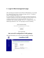
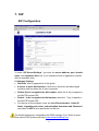
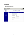
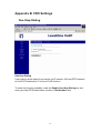
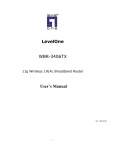
3. Login to Web management page
After connecting your computer to the LAN port of SIP Gateway, you can login
the configuration page by open a browser and type 192.168.1.1 in address
column. The default login name is “root”.
For VOI-4100, there is no LAN port on this model. You have to connect your
computer to WAN port of VOI-4100, and configure the TCP/IP setting of your
computer manually. Set the IP address as 192.168.1.XXX. After set
successfully, open a browser and type 192.168.1.1 in address column. The
default login password is “root”. The login page is shown as following.
Fig.1 Login Page
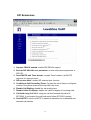
Set correct IP configuration to SIP gateway.
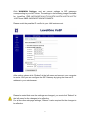
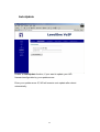
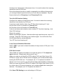
After login Successfully, you can see the welcome page as following.
3
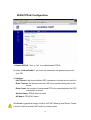
Click WAN/WAN Settings, and set correct settings to SIP gateways
corresponding to your NAT router. The settings in the following image is suitable
for LevelOne FBR-1407/1409TX/1411TX/1412TX/1413TX/1415TX/1417TX/
1418TX and WBR-3402/3403TX/3404TX/3406TX.
Please avoid the possible IP conflict in your LAN environment.
After setting, please click “Reboot” at the left menu and connect your computer
to router. And you can configure the SIP Gateway by typing the new set IP
address in your web browser.
Please be noted that once the settings are changed, you must click “Reboot” at
the left menu for the changes to be effective.
For all the other web page settings, “Reboot” is also required for the changes to
be effective.
4
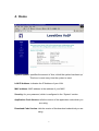
4. Home
System Uptime: specifies the amount of time, which the system has been up.
This time is reset every time the system is reset.
LAN IP Address: indicates the IP Address of your LAN.
MAC address: MAC address is the address of your MAC.
Security: for your password, which is configured in the “System” section.
Application Code Version: tells the version of the application code which you
are using.
Download Code Version: tells the version of the download code which you are
using.
5
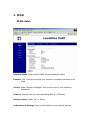
5. WAN
WAN status
Interface Status: these are the details of your interface’s status.
Enabled: “Yes”, lets you know that your interface is enabled and ready to be
used.
Service: either “Routed or Bridged”, tells you the level of your interface’s
connection.
Protocol: refers to how you are transmitting data. (i.e. Ethernet)
Interface Status: either “Up” or “Down”.
Under Network Settings: these are the details of your network settings.
6
Dynamic IP Assignment: “Yes” or “No”, depending on whether or not you are
using a dynamic IP.
IP address: your specified IP.
MAC address: Your specified MAC address.
Subnet Mask: indicates the IP address of your mask.
Default Gateway: is the IP address of the gateway. The gateway IP could be
retrieved from DHCP offer in DHCP mode, or be set up
manually in fixed IP mode.
DNS address: refers to the address of your dynamic name server, if applicable.
VLAN: VLAN tag value encoded in the Ethernet header in all outgoing packets
Priority Tag: Priority Tag value encoded in the Ethernet header in outgoing
packets.
Broadcast Limit & Multicast Limit: Please see the WAN Setting
7
WAN Settings
1. Device Operating Mode: you choose either “Router” or “Bridge”, depending
on your operation.
2. You will check either “Obtain WAN configuration dynamically” or “Specify
fixed WAN configuration”.
When you choose “Obtain WAN configuration dynamically”, the information
is detected automatically through DHCP.
If you choose “Specify fixed WAN configuration”, you are required to enter
the IP address, IP of the Sub mask, IP of the Gateway, and IP of the DNS
Server, if applicable.
3. Multicast Limits:
Broadcast Limit: the value specifies the maximum limit on the percentage of
broadcast packets, which will be bridged to the destination
interface (as a percentage of the source side bandwidth)
8
Multicast Limit: the value specifies the maximum limit on the percentage of
multicast packets, which will be bridged to the destination
interface (as a percentage of the source side bandwidth)
9
WAN PPPoE Configuration
1. Enable PPPoE: “Yes” or “No”, to enable/disable PPPoE
2. Under “Authentication”, you enter the username and password given by
your ISP.
3. Settings:
Idle Timeout: Idle timeout before PPP connection is closed due to inactivity
Echo Timeout: the duration between PPP echo requests being sent to the
server.
Echo Count: the number of unanswered PPP echo requests before the PPP
connection is closed.
Service Name: PPPoE Service name
AC Name: PPPoE AC name
We do not suggest that using LevelOne VoIP SIP Gateway as a Router. Please
connect it behind another NAT router for safety reason.
10
MAC Spoofing Configuration
WAN MAC Address (Spoofed):
This is only available when devices are under the router mode. The spoofed
MAC address to be used by the device’s WAN interfaces, the Ethernet
address of the outgoing packets from the WAN interface would be replaced
with this address. If blank, the WAN interfaces will use the value of MAC.
11
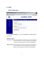
6. LAN
LAN Configuration
1. Under “Network Settings”, you enter the IP address and subnet mask of
your network.
2. Multicast Limits:
Broadcast Limit: the value specifies the maximum limit on the percentage of
broadcast packets, which will be bridged to the destination
interface (as a percentage of the source side bandwidth)
Multicast Limit: the value specifies the maximum limit on the percentage of
multicast packets, which will be bridged to the destination
interface (as a percentage of the source side bandwidth)
12
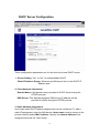
DHCP Server Configuration
These configuration parameters are for the device’s internal DHCP server.
1. Server Setting: “Yes” or “No”, to enable/disable DHCP
Client IP Address Range: Minimum and Maximum limit on the DHCP IP
address pool
2. Client Network Information
Domain Name: LAN domain name provided to DHCP clients during the
OFFER process.
DNS Server: This statically assigned DNS server IP address will be
provided to clients during the OFFER process.
3. Static Address Assignment
Up to eight static DHCP address assignments can be configured. To add a
static IP assignment, enter the LAN device’s host name (must be unique in the
private network) and/or MAC address. Specify the Internal address to be
assigned and press the "Add" button.
13
Router Configuration
These configuration parameters are for the device’s internal router.
1. Dynamic Routing: Whether or not dynamic routing on TX/RX interfaces is
enabled/disabled.
2. Static Routing
Under “Static Routing”, you can specify the routing path of your internal
network.
14
Port Forwarding Configuration
1. Under “Reserved Ports”, specified are the ports, which cannot be forwarded
to the LAN.
2. Under “Port Forwarding to LAN”, you enter the specifications, which you
will be forwarding to the LAN, including port range, protocol(Both, TCP or
UDP), and destination IP address.
Click on “Save NAPT Settings” to save your configurations.
15
7. SIP
SIP Configuration
1. Under “SIP Server Settings”, you enter the server address, port, domain
name, and expiration time unit, if you choose to send a registration request
with an expiration time.
2. Gateway Settings
•
•
Dial Plan: refer to appendix A of this guide
# use as a quick dial function: If this box is checked, the dialed digits
would be sent out when the ‘#’ key is pressed.
•
Enable # to be recognized as dial number: allow the ‘#’ key to appear in
the INVITE request URI
•
Enable * to be recognized as dial number: allow the ‘*’ key to appear in
the INVITE request URI
•
For the line on the endpoint, enter the Line Phone Number, Caller-ID
Name, signalling port value, authentication Username and Password,
and select if AEC is to be performed on this line.
The default settings are compatible with FWD settings. If you`d like to know
more about FWD, please visit http://www.freeworlddialup.com .
16
SIP Extensions
1. Support PRACK method: enable SIP PRACK support.
2. Encode SIP URI with user parameter: encode user=phone parameter in
SIP URI.
3. Send INVITE with Timer header: encode Timer header in all INVITE
requests for ringing timeout
4. SIP session timer: enable SIP session timer function.
5. Conditional Call Forwarding Timer: Forward the call to the pre-configured
number if the phone does not pick up within the timer.
6. Disable Call Waiting: disable the call waiting tone.
7. Disable Caller-ID display: disable the caller-id display of incoming calls.
8. Call Hold using C=0.0.0.0: using the call hold method described in
RFC2543. If unchecked, the call hold would follow RFC3263 method
9. Send NOTIFY: send out NOTIFY request to transferor for unattended and
attended call transfer.
17
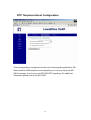
RTP Telephone Event Configuration
This sub-page allows configuration of the out-of-band signalling options for SIP.
Select whether OOB telephone event signalling is to be done using the SIP
INFO message, or to be done via RFC2833 RTP signalling. For additional
information please refer to the RFC2833.
18
ToS/DiffServ
This sub-page is used to configure the Type-of-Service/Diffserv byte values,
which are to be used in the IP header of all transmitted SIP signalling packets
and RTP packets. The ToS/DiffServ byte values are entered as two-digit
hexadecimal values. If no special ToS/DiffServ value is to be used for a
particular traffic type, enter “00” or leave the setting empty.
Press “Save ToS/DiffServ Settings” to save these new settings.
19
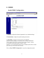
8. CODEC
Audio/CODEC Configuration
1. CODECS: configure the silence suppression to your desired settings.
2. Packetization: configure the packet sending increments.
3. Jitter Buffer: configure the timing of the voice buffering.
Selection between adaptive or fixed jitter buffer. Default = ADAPTIVE
Set the adaptive jitter buffer maximum playout delay. Default = 100ms
or Fixed jitter buffer playout delay. Default = 40ms
Whether or not to automatically switch from an adaptive jitter buffer to a fixed
jitter buffer upon fax/modem tone detection
Click on “Save CODEC Configuration” to save the configurations made.
20
9. SYSTEM
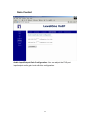
Set Security Password
Configure a password for the system.
21
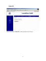
AutoUpdate
Enable an AutoUpdate function, if your want to update your IAD
firmware/configuration by your update server.
Enter your update server IP, IAD will execute auto update after reboot
automatically.
22
Localization
Choose the correct country for a proper impedance match, as well as the NTP
Server, and Time Zone. Check the “Adjust clock for daylight savings”, when
applicable.
Click on “Save Localization Settings”, to save your configurations.
23
Gain Control
Audio Input/Output Gain Configuration: You can adjust the FXS port
input/output audio gain level with this configuration.
24
Caller ID
Select the format of Caller ID to match your phone set CID type.
25
Service Access Configuration
Check the proper boxes enabling LAN and WAN for the HTTP access.
Click on “Save Service Access Settings”, to save the configurations.
26
10.
Download
For both HTTP and TFTP methods, the device will reboot itself into
downloader mode if the main application is being executed, and proceed with
the ROM file download and permanent write of the application to the device’s
flash memory. After the download is completed, the download status page will
be displayed.
27
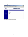
11.
Logout
Click Logout to Logout the system configuration
28
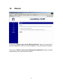
12.
Reboot
Choose the “Reboot and execute Main Application” option, for execution of
the main application which you have configured, once you reboot the system.
Choose the “Reboot and execute Downloader Application” option, to begin
downloading, once you reboot the system.
29
Appendix A. Dial Plans
The SIP code will allow provisioning (via web browser) of the dial plan. A dial plan
gives the unit a map to determine when a complete number has been entered and should
be passed to the gatekeeper for resolution into an IP address. Dial plans are expressed
using the same syntax as used by MGCP NCS specification.
The formal syntax of the dial plan is described in the following notation:
Digit ::= "0" | "1" | "2" | "3" | "4" | "5" | "6" | "7" | "8" | "9"
Timer ::= "T" | "t"
Letter ::= Digit | Timer | "#" | "*" | "A" | "a" | "B" | "b" | "C" | "c"| "D" | "d"
Range ::= "X" | "x" -- matches any digit
| "[" Letters "]" -- matches any of the specified letters
Letters::= Subrange | Subrange Letters
Subrange::= Letter -- matches the specified letter
| Digit "-" Digit -- matches any digit between first and last
Position::= Letter | Range
StringElement::= Position -- matches any occurrence of the position
| Position "." -- matches an arbitrary number of occurrences
including 0
String ::= StringElement | StringElement String
StringList::= String | String "|" StringList
DialPlan::= String | "(" StringList ")"
A dial plan, according to this syntax, is defined either by a (case insensitive) string or by
a list of strings. Regardless of the above syntax, a timer is only allowed if it appears in
the last position in a string (12T3 is not valid). Each string is an alternate numbering
scheme. The unit will process the dial plan by comparing the current dial string against
the dial plan. If the result is under-qualified (partial matches at least one entry), then it
will do nothing further. If the result matches or is over-qualified (no further digits could
possibly produce a match), then it sends the string to the gatekeeper and clear the dial
string. The Timer T is activated when it has all that is required to produce a match. The
period of timer T is 4 seconds. For example, a dial plan of (xxxT|xxxxx) will match
immediately if 5 digits are entered. It will also match after a 4 second pause when 3
digits are entered.
30
Sample Dial Plans
Simple Dial Plan
Allows the dialing of 7 digit numbers (e.g. 5551234) or an operator on 0. Dial plan is
(0T|xxxxxxx)
Non-dialed Line Dial Plan
As soon as the handset is lifted, the unit contacts the gatekeeper (used for systems
where dtmf detection is done in-call). Dial plan is (x.) i.e. match against 0 (or more)
digits. Note: the dot ‘.’
Complex Dial Plan
Local operator on 0, long distance operator on 00, four digit local extension number
starting with 3,4 or 5, seven digit local numbers are prefixed by an 8, two digit star
services (e.g. 69), ten digit long distance prefixed by 91, and international numbers
starting with 9011+variable number of digits.
The dial plan for this is:
(0T|00T|[3-5]xxx|8xxxxxxx|*xx|91xxxxxxxxxx|9011x.T)
31
Appendix B. FXO Settings
One-Step Dialing
One-Step Dialing
It can make a direct dialing from remote via IP network, IAD and PSTN network
to final PSTN destination. It is like a PLAR function.
To make this function available: mark the Enable One-Step Dialing box and
enter your final PSTN destination number in Dial Number field.
32
FXO Setting
Line Side Impedance Setting:
To specify the PSTN or PBX impedance, choose your country from the list.
For most of the cases, once you choose your country, all the other
corresponding settings will be set automatically.
Or please enter the right impedance if you cannot find your country in the list.
For example: if the PSTN line impedance is 600 ohm, please select 600 in this
field. If you choose your country from the list, go directly to Loop Current
Shutdown Detection setting.
If your country is not in the above setting list or your country is in the list
but you still encounter a disconnection failure, you must do “Tone
Detection Frequency Setting” and “Tone On-Off Duration Setting”.
Tone Detection Frequency Setting:
33
Configure the frequencies of disconnect tone. It is used to detect the incoming
disconnect tone by FXO port.
Due to the disconnect tone is usually composed by two different frequencies,
you must get these frequencies from your local telecom standards. Key the
frequencies by Hz in Frequency1 and Frequency2 fields.
Tone On-Off Duration Setting:
Configure the cadence of disconnect tone. It is used to detect the incoming
disconnect tone duration by FXO port.
If you know each duration value, turn CP Tone Auto Learning off. And,
Key the time of tone on duration in Tone-On field.
Key the time of tone off duration in Tone-Off field.
If you do not know each duration value, enable CP Tone Auto Learning. And,
Save FXO settings.
Reboot the system.
Make a call through FXO port. After the callee reply and disconnect, wait for 10
seconds. Enter the FXO setting user interface again. You will find the Tone
On-Off fields filled by values detected.
Turn CP Tone Auto Learning off.
Loop Current Shutdown Detection:
Select “YES” if you want to detect the status of loop current in FXO port. If not,
select “NO”.
FXO Gain Control:
These fields are used to decrease or increase the gains in FXO output and
input channels. Default gain values are all “zero”.
When you make a call from IP to PSTN, adjust FXO Input Gain Control (To
PSTN) to a lower value if PSTN cannot recognize your numbers dialed after
hearing the PSTN dial tone. For example, set “-6” to replace the default “0”.
Always use “6” as a unit for your first trial and find a best suitable number then.
When you make a call from PSTN to IP, adjust FXO Output Gain Control (To IP)
to a lower value if IP cannot recognize your numbers dialed after hearing the
dial tone. For example, set “-6” to replace the default “0”.
Click Save FXO Setting to save all settings to FXO port.
34
For further FXO settings, please contact with your local ISP or visit
www.level1.com for further product information.
35