1
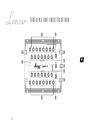
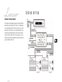
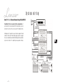
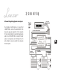
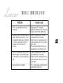
user’s manual
www.lanzar.com
OptiE-15
15-Band
Half/Full Octave
Stereo Equalizer
INTRODUCTION...
Congratulations on your purchase of a new Lanzar Opti signal processor. Opti mobile electronics are some of the most advanced
car audio products available. These quality audio products are designed and engineered to afford you years of uncompromising
musical service. Lanzar has utilized the latest electronic technologies in order to deliver a superb listening experience.
The E-15 Equalizer offers the listener the ability to intensify the listening experience, add realism to their mobile system, overcome
his or her vehicle’s unique acoustic properties, and tailoring the sound to their preference. The E-15 was designed with the
goal of achieving the finest music reproduction.
Although the way it sounds to you is the ultimate decision maker in how you set up your car audio system, we suggest the use
of a sound analyzer to give you exact audio measurements of your car’s interior so that you can achieve precise equalizer settings.
Of course, the E-15 can and should also be adjusted to your preference.
Finally, a tip – once you achieve the optimum settings for your system, don’t keep changing them to suit particular program
material! Also, we suggest you write the settings down and keep this record in case they ever accidently get changed. This
could save hours in having to experiment all over again.
table of contents
general features
2
precautions
3
features and specifications
4-5
system wiring
6-9
mounting and installation
10-11
noise check and system adjustment
12
troubleshooting
13
general features
15 Band Equalizer Controls per Channel in 1/2 and Full Octave Steps
Blue Light Illumination
± 12 dB Boost/Cut at Each Frequency Setting
Front, Rear and Line Outputs
Separate Front, Rear and Line Output Level Controls
Front/Rear Fader Control
Power LED Indicator
EQ Bypass Switch
Gold-Plated Connectors and Terminals
2
Precautions
To prevent short circuits, be sure to disconnect the negative battery ground lead before wiring the system up.
When you finish the installation, be sure to make one more check to be sure everything is done correctly.
Reinstate all car parts that were removed.
Reconnect the negative battery ground lead.
3
features and specifications
4
features and specifications
1. Fader Control
This rotary controls the balance between the front and rear outputs. This fader takes priority
over the fader in your car stereo head unit.
2. Right and Left Channel Equalizer
Controls
The 15 band equalizer controls divide the frequency control range into 1/2 octave steps at
20Hz, 30Hz, 45Hz, 67Hz, 100Hz, 150Hz, 200Hz, 350Hz, 500Hz,800Hz,and at full octave
steps, 1100Hz, 2200Hz, 4400Hz, 8800Hz, 17200Hz. Each rotary control permits the signal
at that control’s frequency to be either increased (by turning clockwise) or decreased (by
turning counter-clockwise) by up to 12 dB. When set to the center detent position, the
control provides no increase or decrease at that frequency.
3. Right and Left Output Level Controls
4. EQ In/Out Switch
5. Line Inputs
6. Front & Rear Outputs
7. Line Outputs
8. Power Indicator
There are separate level controls on the E-15 for both the left and right channel outputs.
When installing and first setting up the system, set the output level controls to the center
detent position for a starting point.
Typically, when the head unit volume is set to approximately the 2 o’clock position your
system is at its ideal volume. Set the head unit volume this way, and then adjust the outputs
on the E-15 accordingly to achieve the ideal volume without over-driving the inputs of your
amplifier, which will create distortion.
The goal in the adjustment is to obtain the best signal-to-noise ratio while obtaining your
desired listening volume.
This switch controls whether or not the E-15 is providing equalization (”IN”) or simply
passing signals through in an unaffected way.
The line inputs are connected to your head units RCA outputs. If your head unit has a fader
that fades between two sets of RCA outputs make sure that the head unit fader is turned
toward the set of RCA connectors that you are using. If your radio has only speaker level
outputs you can connect the E-15 to your head unit via a high/low level adapter (for example,
a Pyramid NS-60 or equivalent). This separate component allows you to connect your
speaker wires from your head unit and the RCA cables from the E-15 while balancing the
head unit’s output and the equalizer’s input.
Connect these outputs to the appropriate inputs of your power amplifier(s). The front outputs
connect to the amplifier driving your front speakers, the rear outputs for the rear amplifier.
Connect this output to another signal processor type device in your system, such as a
crossover. Th1s line output level is unaffected by the fader control.
This indicator lights up when the internal power supply is activated and the unit is operational.
Control Frequencies
Half Octave 20Hz • 30Hz • 45Hz • 67Hz
100Hz • 150Hz • 200Hz
Full Octave
Control Range
Frequency Response
Signal-to-Noise Ratio (A-Wtd)
Input Sensitivity
Maximum Output Voltage
Channel Separation
Power Requirement
Dimensions, WxDxH, inches
(millimeters)
350Hz • 500Hz • 800Hz
1.1KHz • 2.2KHz
4.4KHz • 8.8KHz • 17.2KHz
12dB Boost/Cut
10Hz - 30KHz
100dB
80mv-2.0Volts
for 400mv Output
7.0 Volts
65 dB
11-16 Volts DC
negative ground
11-5/8 x 8-9/32 x 1-1/2
(295 x 210 x 38)
5
Lanzar strives to continually improve and refine its products, as well as to design
new models. Therefore, the product specifications and illustrations in this manual
are subject to change without notice.
System wiring
Standard 4-Channel Output
For standard 4-channel operation, plug both the left and right RCA
outputs from your head unit into the E-15 inputs. The output power
can be distributed to either the front or rear speakers by using the
fader control. With the fader is in the center detent position, you
will have balanced output between your front and rear channels.
Turning the fader to either the front or rear position results in
increased signal strength to that particular side while decreasing
signal strength to the other side.
to
REMOTE
OUTPUT
from
HEAD
UNIT
Head unit (Stereo, DVD Player, Tape Deck, etc.)
TO OUTPUT
OF HEAD UNIT
to BATTERY
6
to AMP
REMOTE ON
to GROUND
TO REAR
AMPLIFIER
TO FRONT
AMPLIFIER
REAR CHANNEL
Speakers
FRONT CHANNEL
Speakers
Speakers
Speakers
System wiring
Dual E-15 2 + 2 Channel Output Using 4 RCA Inputs
Two Model E-15s are required for this configuration. For
more exact control, the E-15s can be configured into separate mono
units with the outputs summing the signal into stereo.
If your head unit has two pairs of RCA outputs, plug both of the left
outputs into the E-15’s left inputs and both of the right outputs
into the E-15’s right inputs. Place both of the fader controls of the
E-15’s into the center detent position.
to
REMOTE
OUTPUT
from
HEAD
UNIT
Head unit (Stereo, DVD Player, Tape Deck, etc.)
TO FRONT OUTPUT
OF HEAD UNIT
to BATTERY
to AMP
REMOTE ON
7
to GROUND
TO REAR
OUTPUT
OF HEAD UNIT
to BATTERY
to AMP
REMOTE ON
to GROUND
to AMP REMOTE ON
TO REAR
AMPLIFIER
TO FRONT
AMPLIFIER
REAR CHANNEL
Speakers
FRONT CHANNEL
Speakers
System wiring
Dual E-15 2 + 2 Channel Output Using 2 RCA INPUTS
Two Model E-15s are required for this configuration. If
your head unit has only one pair of RCA output jacks, you can
achieve the same result by using a pair of Y-adapter cables.
Utilizing two E-15s permits the users to tailor 4 separate 15 band
channels in full stereo. When setting up your system we suggest
the use of a sound analyzer to aid in obtaining exact measurements
of your car’s interior. This permits precise equalizer settings.
to
REMOTE
OUTPUT
from
HEAD
UNIT
Head unit (Stereo,DVD Player, Tape Deck, etc.)
TO OUTPUT
OF HEAD UNIT
to BATTERY
to AMP REMOTE ON
8
to
GROUND
Y-ADAPTER
CABLES
to BATTERY
to AMP REMOTE ON
to GROUND
to AMP
REMOTE ON
TO REAR
AMPLIFIER
TO FRONT
AMPLIFIER
REAR CHANNEL
Speakers
FRONT CHANNEL
Speakers
System wiring
4 Channel Output Using Speaker Level Inputs
If your radio does not have RCA outputs, as is the case with most
standard OEM radios, you can use the speaker outputs from those
head units to supply audio signal to the E-15. The radio and the
E-15 can be connected together by using a high/low level impedance
adapter such as the Pyramid® NS-60 or its equivalent. The proper
adapter is crucial to provide a match with the input of the E-15
which will help to insure low noise and the finest sound quality
from the components.
TO RADIO
SPEAKER WIRES
to
REMOTE
OUTPUT
from
HEAD
UNIT
Head unit (Stereo, DVD Player, Tape Deck, etc.)
to HIGH/LOW ADAPTER
NS- 60
9
to BATTERY
to AMP REMOTE ON
to GROUND
to AMP
REMOTE ON
TO REAR
AMPLIFIER
TO FRONT
AMPLIFIER
REAR CHANNEL
Speakers
FRONT CHANNEL
Speakers
Mounting and installation
Your new Opti Series Octave Equalizer comes complete with all required mounting hardware.
Please read the Installation Precautions section below before installing your Lanzar Opti signal processor, and then refer to the diagrams provided to connect power,
audio input and output connections according to your own system configuration requirements.
Precautions
Mark the location for the mounting screw holes by positioning the Equalizer where you wish to install it and use a scribe (or one of the mounting screws) inserted
in each of the mounting holes to mark the mounting surface. If the mounting surface is carpeted, measure the hole centers and mark with a felt tip pen.
Before you drill or cut any holes, investigate your car’s layout very carefully. Take care when you work near the gas tank, fuel lines, hydraulic line and electrical wiring.
Do not operate the signal processor when it is unmounted. Attach all audio system components securely within the automobile to prevent damage, especially in an
accident.
Do not mount this signal processor so that the wire connections are unprotected or in a pinched condition, or likely to be damaged by nearby objects. Be sure to
select a location inside your vehicle which has adequate ventilation.
Before making or breaking power connections in your system, disconnect the vehicle battery. Confirm that your head unit or other equipment is turned off while
connecting the input and output jacks.
If you need to replace the power fuse, only replace it with a fuse identical to that supplied with the system.
Using a fuse of a different type or rating may result in damage to your system which isn’t covered by the manufacturer’s warranty.
Suggested Tools and Other Parts
• In-line fuse holder
• Felt-tip marking pen
• Electric drill with a Phillips-head screwdriver bit
• Crimping tool or needle-nose pliers
• Wire strippers
• Tape measure and ruler
• Orange wire, 20 gauge or heavier
• Red and Black wire, 18 gauge or heavier
• RCA stereo audio cables (quantity and length determined by application)
• Solder-less connectors or soldering gun with heat shrink tubing
10
• Solder-less connectors or soldering gun with heat shrink tubing
Mounting and installation
Processor Installation
1. Find a suitable location in the vehicle to mount the processor. The E-15 is a trunk mount unit and it should be installed in close proximity to your amplifier system.
You should pick a location that offers easy access to the unit for adjustment.
2. Before starting, disconnect the vehicle’s negative battery ground to prevent short circuits. Bolt the processor to the mounting surface, making sure there is sufficient
air flow around the installation.
3. There are three power terminals on the E-15.
• A red 18 gauge stranded or heavier and insulated wire should be connected to the terminal marked +12V. Wire an in-line fuse holder on this lead as it is the
12V DC wire for the system. This wire should be attached to the switched side of the vehicle’s ignition switch and should have power to it only when the vehicle
is running or the switch has been turned to the accessory position.
• A black stranded wire of at least 18 gauge should be connected to the terminal marked Ground. This is the ground wire for the E-15 and should be attached to
the same ground point with the amplifiers in the system. Keeping this ground wire as short as possible improves the electrical circuit and keeps ground-related
noise problems to a minimum.
• An orange stranded wire of a least 20 gauge should be connected to the terminal marked Remote. This wire connects to your head unit’s remote out or power
antenna lead out. This wire should supply 12 Volts DC any time the radio, CD or cassette are playing. This lead must also be connected to any other components
in your system that utilize a remote turn-on lead for powering up.
4. Connect all line inputs and outputs using high-quality RCA-RCA cables.
5. Recheck all connections before powering up.
6. Set all level controls to their least sensitive positions and set all crossover controls, switches, etc. to the desired frequency or position.
7. Once the system is powered up, set the volume control on the head unit to about the 2 o'clock position, and then set all the amplifiers' level controls for maximum
output level.
8. Now you are ready to start equalizing your vehicle with the E-15.
11
Noise check and system adjustment
NOISE CHECK
Check the entire audio system for noise before permanently securing the EQUALIZER mounting
1. Start the engine.
2. Turn the audio system on.
3. Rev the engine and vary the VOLUME of the audio system to determine if there is any unwanted noise.
If so, turn both the audio system and the engine off. Do not secure the EQUALIZER mounting screws. Refer to the "Trouble Shooting Guide" at this
manual.
4. If the audio system does not have any noise, securely tighten the EQUALIZER mounting screw and double check the wiring cables for safe placement.
SYSTEM ADJUSTMENT
Preliminary Adjustments
Pre-setting the system provides a necessary starting point for fine-tuning the entire audio system to maximum performance.
NOTE: DO NOT MOUNT EQUALIZER UNTIL THE FOLLOWING PROCEDURES HAVE BEEN COMPLETED.
1. Preset each amplifier input gain adjustment at the amplifier to half of maximum.
2. Before turning the audio system on, preset-adjust the front, and rear output level controls, as well as the right channel and left channel Equalizer Control
points.
3. Slowly turn the volume up and listen carefully for: obvious trouble in sound (distortion, no sound, no hiss, total silence). Turn the system off refer to
"Trouble Shooting Guide" at this manual.
Caution
DO NOT ROUTE AUDIO CABLES AND POWER CABLES TOGETHER! THIS CAN CAUSE ENGINE NOISE IN YOUR AUDIO SYSTEM.
ALWAYS DISCONNECT THE SYSTEM FROM THE BATTERY BEFORE ATTEMPTING TO MAKE OR ALTER ANY CONNECTIONS. THIS
PRODUCT IS DESIRED FOR USE IN ANY 12 VOLTS NEGATIVE GROUND ELECTRICAL SYSTEM ONLY. INSTALLING THIS PRODUCT
IN ANY POSITIVE GROUND ELECTRICAL SYSTEM COULD SERIOUSLY DAMAGE THE AUDIO SYSTEM.
12
TBOUBLE SHOOTING GUIDE
PROBLEM
1. There is an audible distortion at a low
volume level.
2. A whining sound can be heard through the
speakers when the audio system is at low
volume with the engine running. The whining
noise remains unchanged or seems to
disappear when the volume level is
increased.
POSSIBLE CAUSE
• Output levels NOT set correctly.
• EQUALIZER frequencies NOT set correctly.
• Check for shorts on the speaker leads.
• Check the red power wire. It muse be
connected directly to the battery.
• Check the system's ground point It muse
make good contact with chassis ground
(bare metal).
• The radio and the EQUALIZER must be
grounded at the same reference point.
3. There is a "motor boating" type of sound
when the engine is running and the audio
system volume is set at a reasonably high
level.
• Check the red power wire. It must be
connected directly to the battery.
• Check the system's ground point. It must
make good contact with chassis ground
(bare metal).
4. High squeal noise from speakers
• This is almost always caused by a poorly grounded RCA patch cord.
13
limited warranty policy
E q u a l i z e r
All Lanzar Signal Processors are carefully constructed and thoroughly tested
before shipment. Units purchased in the USA are warranted to be free of defects
in material and workmanship for three (3) years from the date of purchase. This
warranty is limited to the original retail purchaser of the Signal Processor.
Should the unit fail due to a factory defect in material or workmanship, your unit
will be repaired or replaced at the sole discretion of Lanzar.
To obtain warranty service, you must first call our Consumer Return Hotline
number at (718) 236-6948 to obtain a Return Authorization (RA) number. This
RA Number must appear on the outside of your package and on all paperwork
relating to your return.
When returning the unit to us for warranty service, it must be carefully packed
and shipped prepaid to:
R.A. # ______________
Lanzar Service Center
1600 63rd Street
Brooklyn, NY 11204
www.lanzar.com
You must also include the following items with your return:
• A copy of your sales receipt or other proof of purchase
• A brief letter indicating the problem you are experiencing with the
product
• Include in your letter your return address, daytime phone number
and RA Number
• Also include a check or money order for $20.00 for return shipping,
handling and insurance, or provide your VISA/MasterCard number
with expiration date.
Our obligation under this warranty is limited to the repair or replacement
of the defective unit when it is returned to us prepaid. This warranty will
be considered void if the unit was tampered with, improperly serviced,
or subject to misuse, neglect or accidental damage.
All implied warranties of merchantability and fitness for a particular
purpose are limited in duration to the length of the warranty. Lanzar
expressly disclaims any liability for incidental or consequential damages
caused by product defects. This warranty does not cover any expense
incurred in the removal and/or reinstallation of the Signal Processor.
Lanzar’s total liability will not exceed the purchase price of the Signal
Processor.
Some states do not allow the exclusion or limitation of incidental or
consequential damages, or limitations on how long an implied warranty
lasts, so the above limitations and exclusions may not apply to you.
This warranty gives you specific legal rights, and you may also have
other rights which vary from state to state.