1
EDS Device Servers/Terminal Servers
User Guide
EDS4100
EDS8PR
EDS16PR
EDS32PR
Part Number 900-433
Revision F November 2007
Copyright & Trademark
© 2006, 2007 Lantronix. All rights reserved. No part of the contents of this book may be
transmitted or reproduced in any form or by any means without the written permission of
Lantronix. Printed in the United States of America.
Ethernet is a trademark of XEROX Corporation. UNIX is a registered trademark of The
Open Group. Windows 95, Windows 98, Windows 2000, and Windows NT are
trademarks of Microsoft Corp. Netscape is a trademark of Netscape Communications
Corporation.
Contacts
Lantronix Corporate Headquarters
15353 Barranca Parkway
Irvine, CA 92618, USA
Phone: 949-453-3990
Fax:
949-453-3995
Technical Support
Online: www.lantronix.com/support
Sales Offices
For a current list of our domestic and international sales offices, go to the Lantronix web
site at www.lantronix.com/about/contact .
Disclaimer & Revisions
Operation of this equipment in a residential area is likely to cause interference, in which
case the user, at his or her own expense, will be required to take whatever measures
may be required to correct the interference.
Changes or modifications to this device not explicitly approved by Lantronix will void the
user's authority to operate this device.
Attention: With the purchase of the EDS, the OEM agrees to an OEM firmware license
agreement that grants the OEM a non-exclusive, royalty-free firmware license to use and
distribute the binary firmware image provided, only to the extent necessary to use the
EDS hardware. For further details, please see the EDS OEM firmware license
agreement.
The information in this guide may change without notice. The manufacturer assumes no
responsibility for any errors that may appear in this guide.
Date
Rev. Comments
3/06
10/06
12/06
1/07
11/07
A
B
D
E
F
EDS Device Servers User Guide
Initial Document
EDS16PR and EDS32PR products added.
German and English TUV certification added.
EDS8PR products added.
Added LPD, Terminal, Host, RSS, and RTC pages; updated; XML and
other pages.
2
Contents
1: Preface
11
Purpose and Audience_______________________________________________ 11
Summary of Chapters _______________________________________________ 11
Additional Documentation ____________________________________________ 12
2: Introduction
13
EDS4100 Overview _________________________________________________ 13
Features ______________________________________________________________ 14
EDS8PR, EDS16PR, and EDS32PR Overview ____________________________ 14
Features ______________________________________________________________ 15
Evolution OS™ ____________________________________________________ 15
Web-Based Configuration and Troubleshooting _______________________________ 16
Command-Line Interface (CLI)_____________________________________________ 16
SNMP Management _____________________________________________________ 16
XML-Based Architecture and Device Control__________________________________ 16
Really Simple Syndication (RSS)___________________________________________ 16
Enterprise-Grade Security ________________________________________________ 16
Troubleshooting Capabilities ______________________________________________ 17
Applications _______________________________________________________ 18
Building Automation/Security ______________________________________________ 18
Industrial Automation ____________________________________________________ 18
Medical/Healthcare______________________________________________________ 18
Retail Automation/Point-of-Sale ____________________________________________ 19
Terminal Server/Console Management ______________________________________ 19
Traffic Management _____________________________________________________ 19
3: Installation: EDS4100
20
Package Contents __________________________________________________ 20
User-Supplied Items ________________________________________________ 20
Identifying Hardware Components______________________________________ 21
Serial Ports____________________________________________________________ 22
Ethernet Port __________________________________________________________ 23
Terminal Block Connector ________________________________________________ 23
LEDs_________________________________________________________________ 23
Reset Button___________________________________________________________ 24
Physically Installing the EDS4100 ______________________________________ 24
EDS Device Servers User Guide
3
Contents
Finding a Suitable Location _______________________________________________ 24
Connecting the EDS4100_________________________________________________ 24
4: Installation: EDS8PR, EDS16PR and EDS32PR
26
Package Contents __________________________________________________ 26
User-Supplied Items ________________________________________________ 26
Identifying Hardware Components______________________________________ 27
Serial Ports____________________________________________________________ 28
Ethernet Port __________________________________________________________ 28
LEDs_________________________________________________________________ 28
Reset Button___________________________________________________________ 29
Physically Installing the EDS8/16/32PR__________________________________ 29
Finding a Suitable Location _______________________________________________ 29
Connecting the EDS8/16/32PR ____________________________________________ 29
5: Getting Started
31
Using DeviceInstaller ________________________________________________ 31
Starting DeviceInstaller __________________________________________________ 31
Viewing EDS Properties __________________________________________________ 32
Configuration Methods_______________________________________________ 34
Configuring from the Web Manager Interface _________________________________ 34
Configuring via an SSH/Telnet Session or Serial Port Using the CLI _______________ 34
Configuring from the XML Interface _________________________________________ 35
6: Configuration Using the Web Manager
36
Accessing the Web Manager through a Web Browser ______________________ 36
Navigating Through the Web Manager __________________________________ 38
Device Status Page _________________________________________________ 47
7: Network, Line, Tunnel, and Terminal Settings
48
Network Configuration Page __________________________________________ 48
Line Settings Pages _________________________________________________ 51
Line – Statistics Page____________________________________________________ 52
Line - Configuration Page ________________________________________________ 53
Line – Command Mode Page _____________________________________________ 55
Tunnel Pages______________________________________________________ 56
Tunnel – Statistics Page _________________________________________________ 56
Tunnel – Serial Settings Page _____________________________________________ 57
Tunnel – Start/Stop Characters Page _______________________________________ 59
Tunnel – Accept Mode Page ______________________________________________ 61
Tunnel – Connect Mode Page _____________________________________________ 63
EDS Device Servers User Guide
4
Contents
Tunnel – Disconnect Mode Page ___________________________________________ 66
Tunnel – Packing Mode Page _____________________________________________ 68
Tunnel – Modem Emulation Page __________________________________________ 69
Tunnel – AES Keys Page_________________________________________________ 70
Terminal Page _____________________________________________________ 72
Host Page ________________________________________________________ 73
Login Connect Menu ________________________________________________ 75
8: Services Settings
76
DNS Page ________________________________________________________ 76
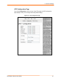
SNMP Page _______________________________________________________ 77
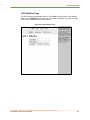
FTP Page_________________________________________________________ 79
TFTP Page________________________________________________________ 80
Syslog Page_______________________________________________________ 81
HTTP Pages ______________________________________________________ 82
HTTP Statistics Page ____________________________________________________ 82
HTTP Configuration Page ________________________________________________ 82
HTTP Authentication Page________________________________________________ 85
RSS Page ________________________________________________________ 88
LPD Pages________________________________________________________ 89
LPD Statistics Page _____________________________________________________ 90
LPD Configuration Page _________________________________________________ 91
9: Security Settings
93
SSH Pages _______________________________________________________ 93
SSH Server: Host Keys Page _____________________________________________ 93
SSH Server: Authorized Users Page ________________________________________ 96
SSH Client: Known Hosts Page ____________________________________________ 97
SSH Client: Users Page __________________________________________________ 98
SSL Page________________________________________________________ 101
10: Maintenance and Diagnostics Settings
105
Filesystem Pages__________________________________________________ 105
Filesystem Statistics Page _______________________________________________ 105
Filesystem Browser Page _______________________________________________ 106
Protocol Stack Page _______________________________________________ 109
IP Address Filter Page ______________________________________________ 110
Query Port Page __________________________________________________ 112
Diagnostics Pages _________________________________________________ 113
Diagnostics: Hardware Page _____________________________________________ 113
EDS Device Servers User Guide
5
Contents
MIB-II Network Statistics Page____________________________________________ 114
IP Sockets Page_______________________________________________________ 115
Diagnostics: Ping Page _________________________________________________ 116
Diagnostics: Traceroute Page ____________________________________________ 117
Diagnostics: DNS Lookup Page___________________________________________ 118
Diagnostics: Memory Page ______________________________________________ 118
Diagnostics: Buffer Pools ________________________________________________ 120
Diagnostics: Processes Page ____________________________________________ 120
Real Time Clock Page ______________________________________________ 122
System Page _____________________________________________________ 123
11: Advanced Settings
125
Email Pages______________________________________________________ 125
Email Statistics Page ___________________________________________________ 125
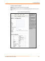
Email Configuration Page _______________________________________________ 126
CLI Pages _______________________________________________________ 128
Command Line Interface Statistics Page ____________________________________ 128
Command Line Interface Configuration Page ________________________________ 129
XML Pages ______________________________________________________ 131
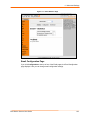
XML: Export Configuration Page __________________________________________ 131
XML: Export Status ____________________________________________________ 133
XML: Import Configuration Page __________________________________________ 135
12: Updating Firmware
141
Obtaining Firmware ________________________________________________ 141
Upgrading Using DeviceInstaller ______________________________________ 141
Loading New Firmware _________________________________________________ 141
Updating the Boot Loader from DeviceInstaller _______________________________ 141
Updating Firmware _____________________________________________________ 142
A: Factory Default Configuration
143
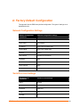
Network Configuration Settings _______________________________________ 143
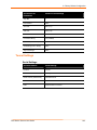
Serial Port Line Settings ____________________________________________ 143
Tunnel Settings ___________________________________________________ 144
Serial Settings ________________________________________________________ 144
Start/Stop Characters___________________________________________________ 145
Accept Mode _________________________________________________________ 145
Connect Mode ________________________________________________________ 145
Disconnect Mode ______________________________________________________ 146
Packing Mode_________________________________________________________ 146
Modem Emulation _____________________________________________________ 147
EDS Device Servers User Guide
6
Contents
AES Keys ____________________________________________________________ 147
Host Settings _____________________________________________________ 147
Terminal Settings __________________________________________________ 148
DNS Settings _____________________________________________________ 148
SNMP Settings____________________________________________________ 148
FTP Settings _____________________________________________________ 149
TFTP Settings ____________________________________________________ 149
Syslog Settings ___________________________________________________ 149
HTTP Settings ____________________________________________________ 150
Configuration _________________________________________________________ 150
Authentication_________________________________________________________ 150
RSS ____________________________________________________________ 150
CLI Settings ______________________________________________________ 151
Telnet _______________________________________________________________ 151
Email Settings ____________________________________________________ 151
LPD Settings _____________________________________________________ 152
IP Address Filter __________________________________________________ 152
Query Port Settings ________________________________________________ 152
System Settings ___________________________________________________ 153
Real Time Clock___________________________________________________ 153
Protocol Stack ____________________________________________________ 153
TCP ________________________________________________________________ 153
ICMP _______________________________________________________________ 153
ARP ________________________________________________________________ 153
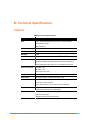
B: Technical Specifications
154
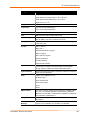
EDS4100 ________________________________________________________ 154
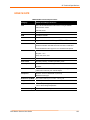
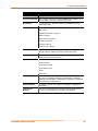
EDS8/16/32PR____________________________________________________ 156
C: Networking and Security
158
SSH ____________________________________________________________ 158
How Does SSH Authenticate? ____________________________________________ 158
What Does SSH Protect Against? _________________________________________ 158
SSL ____________________________________________________________ 159
Benefits of SSL________________________________________________________ 159
How SSL Works _______________________________________________________ 159
Digital Certificates _____________________________________________________ 160
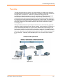
Tunneling ________________________________________________________ 161
Tunneling and the EDS _________________________________________________ 162
EDS Device Servers User Guide
7
Contents
Connect Mode ________________________________________________________ 162
Accept Mode _________________________________________________________ 163
Disconnect Mode ______________________________________________________ 163
Packing Mode_________________________________________________________ 164
Modem Emulation _________________________________________________ 164
Command Mode_______________________________________________________ 165
D: Technical Support
167
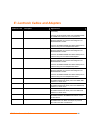
E: Lantronix Cables and Adapters
168
F: Compliance
169
Lithium Battery Notice ______________________________________________ 170
Installationsanweisungen____________________________________________ 170
Rackmontage _________________________________________________________ 170
Energiezufuhr _________________________________________________________ 170
Erdung ______________________________________________________________ 170
Installation Instructions _____________________________________________ 170
Rack Mounting ________________________________________________________ 170
Input Supply __________________________________________________________ 171
Grounding____________________________________________________________ 171
G: Warranty
172
Index
173
Figures
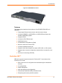
Figure 2-1. EDS4100 4 Port Device Server.............................................................. 14
Figure 2-2. EDS16PR Device Server........................................................................ 15
Figure 3-1. Front View of the EDS4100 ..................................................................... 21
Figure 3-2. Back View of the EDS4100 ..................................................................... 21
Figure 3-3. RS-232 Serial Port Pins (Serial Ports 1, 2, 3, 4) ..................................... 22
Figure 3-4. RS-422/RS-485 Serial Port Pins ............................................................. 22
Figure 3-5. Terminal Block Connector Pin Assignments ........................................... 23
Figure 3-6 .Back Panel LEDs..................................................................................... 23
Figure 3-7. Example of EDS4100 Connections ......................................................... 25
Figure 4-1. Front View of the EDS16PR .................................................................... 27
Figure 4-2. Back View of the EDS16PR .................................................................... 27
Figure 4-3. RJ45 Serial Port ...................................................................................... 28
Figure 4-4. Example of EDS16PR Connections ........................................................ 30
Figure 5-1. Lantronix DeviceInstaller ........................................................................ 32
Figure 5-2. EDS4100 Properties................................................................................ 33
Figure 6-1. Prompt for User Name and Password..................................................... 36
Figure 6-2. Web Manager Device Status Page ......................................................... 37
Figure 6-3. Web Manager Menu Structure (1 of 5).................................................... 40
Figure 6-4. Web Manager Menu Structure (2 of 5).................................................... 41
Figure 6-5. Web Manager Menu Structure (3 of 5).................................................... 42
EDS Device Servers User Guide
8
Contents
Figure 6-6. Web Manager Menu Structure (4 of 5).................................................... 43
Figure 6-7. Web Manager Menu Structure (5 of 5)................................................... 44
Figure 6-8. Components of the Web Manager Page ................................................. 45
Figure 6-9. EDS Menu ............................................................................................... 46
Figure 6-10. Device Status Page (EDS4100) ............................................................ 47
Figure 7-1. Network Configuration ............................................................................. 49
Figure 7-2. Line – Statistics Page .............................................................................. 52
Figure 7-3. Line – Configuration Page ....................................................................... 53
Figure 7-4. Line – Command Mode Page.................................................................. 55
Figure 7-5. Tunnel - Statistics Page.......................................................................... 57
Figure 7-6. Tunnel – Serial Settings Page ................................................................. 58
Figure 7-7. Tunnel – Start/Stop Chars Page ............................................................. 60
Figure 7-8. Tunnel – Accept Mode Page .................................................................. 61
Figure 7-9. Connect Mode Page................................................................................ 64
Figure 7-10. Tunnel – Disconnect Mode Page .......................................................... 67
Figure 7-11. Tunnel – Packing Mode Page ............................................................... 68
Figure 7-12. Tunnel – AES Keys Page ...................................................................... 71
Figure 7-13. Terminal Page ....................................................................................... 72
Figure 7-14. Host Page.............................................................................................. 74
Figure 8-1. DNS Page................................................................................................ 76
Figure 8-2. SNMP Page............................................................................................. 77
Figure 8-3. FTP Page................................................................................................. 79
Figure 8-4. TFTP Page .............................................................................................. 80
Figure 8-5. Syslog Page ............................................................................................ 81
Figure 8-6. HTTP Statistics Page .............................................................................. 82
Figure 8-7. HTTP Configuration Page ....................................................................... 83
Figure 8-8. HTTP Authentication Page ...................................................................... 86
Figure 8-9. RSS Page ................................................................................................ 88
Figure 8-10. LPD Statistics Page............................................................................... 90
Figure 8-11. LPD Configuration Page........................................................................ 91
Figure 9-1. SSH Server: Host Keys Page.................................................................. 94
Figure 9-2. SSH Server: Authorized Users Page ...................................................... 96
Figure 9-3. SSH Client: Known Hosts Page .............................................................. 97
Figure 9-4. SSH Client: Users Page .......................................................................... 99
Figure 9-5. SSL Page (top) ...................................................................................... 101
Figure 9-6. SSL Page (Bottom)................................................................................ 102
Figure 10-1. Filesystem Statistics Page................................................................... 106
Figure 10-2. Filesystem Browser Page.................................................................... 107
Figure 10-3. Protocol Stack Page ............................................................................ 109
Figure 10-4. IP Address Filter Page......................................................................... 111
Figure 10-5. Query Port Page.................................................................................. 112
Figure 10-6. MIB-II Network Statistics Page............................................................ 114
Figure 10-7 IP Sockets Page ................................................................................... 115
Figure 10-8 Diagnostics: Ping Page ........................................................................ 116
Figure 10-9 Diagnostics: Traceroute Page .............................................................. 117
Figure 10-10 Diagnostics: DNS Lookup Page ......................................................... 118
Figure 10-11 Diagnostics: Memory Page ................................................................ 119
Figure 10-12. Diagnostics: Buffer Pools Page......................................................... 120
Figure 10-13. Diagnostics: Processes Page............................................................ 121
Figure 10-14. Real Time Clock Page....................................................................... 122
Figure 10-15. System Page ..................................................................................... 123
Figure 11-1. Email Statistics Page........................................................................... 126
Figure 11-2. Email Configuration Page.................................................................... 127
Figure 11-3. Command Line Interface Statistics Page ............................................ 129
Figure 11-4. Command Line Interface Configuration Page ..................................... 130
Figure 11-5. XML : Export Configuration Page........................................................ 132
EDS Device Servers User Guide
9
Contents
Figure 11-6. XML: Export Status Page .................................................................... 134
Figure 11-7. XML: Import Configuration Page ......................................................... 135
Figure 11-8. XML: Import Configuration from External File ..................................... 136
Figure 11-9. XML: Import from Filesystem .............................................................. 137
Figure 11-10. XML: Import Line(s) from Single Line Settings on the Filesystem ... 139
EDS Device Servers User Guide
10
1: Preface
Purpose and Audience
This guide describes how to install, configure, use, and update the EDS4100 4-Port,
EDS8PR 8-Port, EDS16PR 16-Port, and EDS32PR 32-Port Device Servers. It is for
users who will use the EDS to network-enable their serial devices.
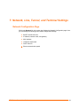
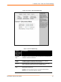
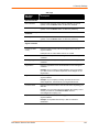
Summary of Chapters
The remaining chapters in this guide include:
Chapter
Description
2: Introduction
Main features of the EDS device servers and the applications for which
they are suited.
3: Installation: EDS4100
Instructions for getting the EDS4100 device server up and running.
Includes a description of hardware components.
4: Installation: EDS8PR,
EDS16PR and EDS32PR
Instructions for getting the EDS8PR, EDS16PR and EDS32PR device
server up and running. Includes a description of hardware components.
5: Getting Started
Instructions for starting DeviceInstaller and viewing current configuration
settings. Introduces methods of configuring the EDS.
6:Configuration Using the Web
Manager
Instructions for using the web interface to configure EDS device servers.
7: Network, Line, Tunnel, and
Terminal Settings
Instructions for using the web interface to configure network, serial line,
and tunnel settings.
8: Services Settings
Instructions for using the web interface to configure settings for DNS,
SNMP, FTP, and other services.
9: Security Settings
Instructions for using the web interface to configure SSH and SSL security
settings.
10: Maintenance and
Diagnostics
Instructions for using the web interface to maintain the EDS, view statistics,
files, and logs, and diagnose problems.
11: Advanced Settings
Instructions for using the web interface to configure email, CLI, and XML
settings.
12: Updating Firmware
Instructions for upgrading the EDS firmware.
A: Factory Default
Configuration
Quick reference of the EDS factory-default configuration settings.
B: Technical Specifications
Tables of technical data about the products...
EDS Device Servers User Guide
11
1: Preface
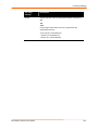
Chapter
Description
C: Networking and Security
In-depth description of networking and network security as it relates to the
EDS device servers.
D: Technical Support
Information about contacting Lantronix Technical Support.
F: Compliance
Information about the products' compliance with regulatory standards.
G: Warranty
Provides information on the Lantronix warranty for the EDS.
Additional Documentation
The following guide is available on the product CD or the Lantronix Web site:
www.lantronix.com.
Document
Description
EDS Device Server Quick
Start Guide
Provides the steps for getting the EDS up and running.
EDS Device Server
Command Reference
Describes how to configure the EDS using Telnet or the serial
port and summarizes the CLI and XML configuration
commands.
Secure Com Port Redirector
User Guide
Provides information for using the Lantronix Windows-based
utility to create secure virtual com ports.
EDS Device Servers User Guide
12
2: Introduction
This chapter introduces the Lantronix EDS family of device servers. It provides an
overview of the products, lists their key features, and describes the applications for which
they are suited.
EDS is a unique, hybrid Ethernet terminal and multi-port device server product designed
to remotely access and manage virtually all of your IT/networking equipment and servers,
as well as edge devices such as medical equipment, kiosks, POS/retail terminals,
security equipment and much more.
EDS device servers contain all the components necessary to deliver full network
connectivity to virtually any kind of serial device, a reliable TCP/IP protocol stack, and a
variety of remote management capabilities. They boast an innovative design and run on
Lantronix’s leading-edge Evolution OS™, our powerful real-time networking operating
system that delivers an unprecedented level of intelligence and security to networked
equipment.
Delivering a data center-grade, programmable device computing and networking platform
for integrating “edge” equipment into the enterprise network, rack-mountable EDS models
are available in 8, 16, and 32 port configurations.
EDS4100 Overview
The EDS4100 is a compact, easy-to-use device server that gives you the ability to
network-enable asynchronous RS-232 and RS-422/485 serial devices. It can deliver fully
transparent RS-232/422 point-to-point connections and RS-485 multi-drop connections
without requiring modifications to existing software or hardware components in your
application.
Note: RS-485 circuits support 32 full-load devices or 128 quarter-load devices.
Each EDS4100 RS-485 port, however, counts as one device, leaving up to 31
full-load or 127 quarter-load devices that can be connected to the RS-485 circuit.
The EDS4100 device server supports the Power-over-Ethernet (PoE) standard.
With PoE, power is supplied to the EDS over the Ethernet cable, by either an
Ethernet switch or a midspan device. Being able to draw power through the
Ethernet cable eliminates power supply and cord clutter. It also allows the EDS to
be located in areas where power is not typically available.
Ports 1 through 4 support RS-232 devices.
Ports 1 and 3 also support RS-422/485 devices.
EDS Device Servers User Guide
13
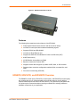
2: Introduction
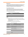
Figure 2-1. EDS4100 4 Port Device Server
Features
The following list summarizes the key features of the EDS4100.
Dual-purpose Ethernet terminal server and device server design
Includes four serial ports with hardware handshaking signals
Supports RS-232 and RS-422/485
Includes one RJ45 Ethernet port
Supports the IEEE 802.3af standard for Power-over-Ethernet (PoE)
8 MB Flash memory
32 MB Random Access Memory (RAM)
Based on Lantronix’s Evolution OS™
Supports secure data encryption by means of AES, SSH, or SSL sessions
Supports three convenient configuration methods (Web, command line, and
XML)
Print server functionality (LPR/LPD)
EDS8PR, EDS16PR, and EDS32PR Overview
The EDS8PR (8 serial ports), EDS16PR (16 serial ports), and EDS32PR (32 serial ports)
are compact easy-to-use, rack-mountable device servers that give you the ability to
network-enable asynchronous RS-232 serial devices. They provide fully transparent RS232 point-to-point connections without requiring modifications to existing software or
hardware components in your application.
EDS Device Servers User Guide
14
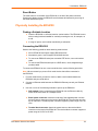
2: Introduction
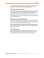
Figure 2-2. EDS16PR Device Server
Features
The following list summarizes the key features of the EDS8PR, EDS16PR, and
EDS32PR.
Dual-purpose Ethernet terminal server and device server design
Includes 8 (EDS8PR), 16 (EDS16PR) or 32 (EDS32PR) serial ports with
hardware handshaking signals
Supports RS-232
Includes one RJ45 Ethernet port
8 MB Flash memory
32 MB Random Access Memory (RAM)
Based on Lantronix’s Evolution OS™
Includes a dedicated console port
Supports secure data encryption by means of AES, SSH, or SSL sessions
Supports three convenient configuration methods (Web, command line, and
XML)
Print server functionality (LPR/LPD)
Evolution OS™
EDS device servers incorporate Lantronix’s Evolution OS™. Key features of the
Evolution OS™ include:
Built-in Web server for configuration and troubleshooting from Web-based
browsers
CLI configurability
SNMP management
XML data transport and configurability
Really Simple Syndication (RSS) information feeds
Enterprise-grade security with SSL and SSH
EDS Device Servers User Guide
15
2: Introduction
Comprehensive troubleshooting tools
Web-Based Configuration and Troubleshooting
Built upon popular Internet-based standards, the EDS enables users to configure,
manage, and troubleshoot efficiently through a simplified browser-based interface that
can be accessed anytime from anywhere. All configuration and troubleshooting options
are launched from a well-organized, multi-page interface. Users can access all
functionality via a Web browser, allowing them flexibility and remote access. As a result,
users can enjoy the twin advantages of decreased downtime (based on the
troubleshooting tools) and the ability to implement configuration changes easily (based
on the configuration tools).
In addition, users can load their own Web pages onto the EDS to facilitate monitoring and
control of their own serial devices that are attached to the EDS.
Command-Line Interface (CLI)
Making the edge-to-enterprise vision a reality, the EDS with the Evolution OS™ uses
industry-standard tools for configuration, communication, and control. For example, the
Evolution OS™ uses a Cisco®-like command line interface (CLI) whose syntax is very
similar to that used by data center equipment such as routers and hubs.
SNMP Management
The EDS supports full SNMP management, making it ideal for applications where device
management and monitoring are critical. These features allow networks with SNMP
capabilities to correctly diagnose and monitor EDS device servers.
XML-Based Architecture and Device Control
XML is a fundamental building block for the future growth of M2M networks. The EDS
supports XML-based configuration setup records that makes device configuration
transparent to users and administrators. The XML is easily editable with a standard text
or XML editor.
Really Simple Syndication (RSS)
The EDS supports Really Simple Syndication (RSS), a rapidly emerging technology for
streaming and managing on-line content. RSS feeds all the configuration changes that
occur on the device. The feed is then read (polled) by an RSS aggregator. More powerful
than simple email alerts, RSS uses XML as an underlying Web page transport and adds
intelligence to the networked device while not taxing already overloaded email systems.
Enterprise-Grade Security
Without the need to disable any features or functionality, the Evolution OS™ provides the
EDS the highest level of security possible. This ‘data center grade’ protection ensures
that each device on the M2M network carries the same level of security as traditional IT
networking equipment in the corporate data center.
With built-in SSH and SSL, secure communications can be established between the EDS
serial ports and the remote end device or application. By protecting the privacy of serial
data being transmitted across public networks, users can maintain their existing
EDS Device Servers User Guide
16
2: Introduction
investment in serial technology, while taking advantage of the highest data-protection
levels possible.
SSH and SSL can:
Verify the data received came from the proper source
Validate that the data transferred from the source over the network has not
changed when it arrives at its destination (shared secret and hashing)
Encrypt data to protect it from prying eyes and nefarious individuals
Provide the ability to run popular M2M protocols over a secure SSH connection
In addition to keeping data safe and accessible, the EDS has robust defenses to hostile
Internet attacks such as denial of service (DoS), which can be used to take down the
network. Moreover, the EDS cannot be used to bring down other devices on the network.
The EDS can be used with Lantronix’s Secure Com Port Redirector (SCPR) to encrypt
COM port-based communications between PCs and virtually any electronic device.
SCPR is a Windows application that creates a secure communications path over a
network between the computer and serial-based devices that are traditionally controlled
via a COM port. With SCPR installed at each computer, computers that were formerly
“hard-wired” by serial cabling for security purposes or to accommodate applications that
only understood serial data can instead communicate over an Ethernet network or the
Internet.
The EDS also supports a variety of popular cipher technologies including:
Advanced Encryption Standard (AES)
Triple Data Encryption Standard (3DES)
RC4
Hashing algorithms such as Secure Hash Algorithm (SHA-1) and MD5
Troubleshooting Capabilities
The EDS offers a comprehensive diagnostic toolset that lets you troubleshoot problems
quickly and easily. Available from the Web Manager, CLI, and XML interfaces, the
diagnostic tools let you:
View critical hardware, memory, MIB-II, buffer pool, and IP socket information.
Perform ping and traceroute operations.
Conduct forward or backup DNS lookup operations.
View all processes currently running on the EDS, including CPU utilization and
total stack space available.
EDS Device Servers User Guide
17
2: Introduction
Applications
EDS device servers deliver simple, reliable, and cost-effective network connectivity for all
your serial devices and address the growing need to connect individual devices to the
network over industry-standard Ethernet connections. The EDS is ideal for a variety of
applications, including:
Building automation/security
Industrial automation
Medical/healthcare
Retail automation/point-of-sale
Console management
Traffic management
Building Automation/Security
Automating, managing, and controlling many different aspects of a building is possible
with the EDS. It can overcome the hurdle of stand-alone networks or individual control
systems that are not able to communicate with each other, and not able to share vital
data, in a cost effective way.
The EDS can also be used to manage equipment and devices centrally over a new or
existing Ethernet network to improve the safety and comfort of building occupants, while
lowering heating, ventilating, air conditioning (HVAC), lighting, and overall energy
operating costs through centralized management and monitoring.
Industrial Automation
Today’s manufacturing facilities face the common challenges of productivity
improvements, inventory management, and quality control. From warehouse to
automotive environments, the need to attach the following devices, whether new or
legacy, continues to grow:
Programmable Logic Controllers (PLCs), Computer Numeric Control and Direct
Numeric Control (CNC/DNC) equipment, process and quality-control equipment
Pump controllers
Bar-code readers and scanners, operator displays, scales, and weighing stations
Printers, machine-vision systems, and other types of manufacturing equipment
The EDS is well suited to deliver network connectivity to all of these devices.
Medical/Healthcare
Hospitals, clinics, and laboratories face rapidly growing needs to deliver medical
information accurately, quickly, and easily, whether at bedside, the nurse’s station, or
anywhere in the facility. The goal to improve healthcare services, however, is balanced
with the need to keep the bottom line from exceeding already constrained budgets.
The EDS can network enable medical equipment and devices using the hospital’s
existing Ethernet network to improve patient care and slash operating costs. This allows
EDS Device Servers User Guide
18
2: Introduction
medical staff members to easily monitor and control equipment over the network, whether
it is located at the point of care, in a laboratory, or somewhere else in the building, all
resulting in improved quality of service and reduced operational costs.
Retail Automation/Point-of-Sale
Having the right solution in the store to manage deliveries, track orders, and keep pricing
current are all improvements that the EDS can offer to make retail operations more
successful. From big to small, one store to thousands of outlets, the EDS can empower
point-of-sale (POS) devices to share information across the network effectively.
With the EDS, retailers can increase and streamline productivity quickly and easily by
network-enabling serial devices like card swipe readers, bar-code scanners, scales, cash
registers, and receipt printers.
Terminal Server/Console Management
Remote offices can have routers, PBXs, servers and other networking equipment that
require remote management from the corporate facility. The EDS easily attaches to the
serial ports on a server, Private Branch Exchange (PBX), or other networking equipment
to deliver central, remote monitoring and management capability.
With the menu system on the EDS, connections to the console ports of the attached
devices as well as Ethernet hosts, such as Unix servers or another EDS, can easily be
picked from a user-defined menu. This allows console ports across multiple networks to
be accessed from one EDS.
Traffic Management
With the ubiquity of Ethernet networks, managing cities over Ethernet is now within
reach. The EDS provides an easy conversion from serial ports on traffic cameras,
billboards, and traffic lights to Ethernet. The EDS obviates the need for long-haul
modems and enables the management of traffic equipment over the network.
EDS Device Servers User Guide
19
3: Installation: EDS4100
This chapter describes how to install the EDS4100 device server.
Package Contents
Your EDS4100 package includes the following items:
One EDS4100 device server
One DB9F-to-DB9Fnull modem cable
One product CD that includes this User Guide, the Command Reference, and the
Quick Start guide.
A printed Quick Start guide
Your package may also include a power supply.
User-Supplied Items
To complete your EDS4100 installation, you need the following items:
RS-232 and/or RS-422/485 serial devices that require network connectivity:
−
Each EDS4100 serial port supports a directly connected RS-232 serial
device.
− Ports 1 and 3 also support RS-422/485 and can accommodate 31 full-load
RS-485 multi-drop devices or 127 quarter-load RS-485 multi-drop devices
per port, for a total of 62 full-load or 254 quarter-load devices.
A serial cable for each serial device to be connected to the EDS4100. One end of
the cable must have a female DB9 connector to connect to the EDS4100 serial
port. The connector on the other end must be configured for your serial device.
Note: To connect an EDS4100 serial port to another DTE device, you will need a
null modem cable, such as the one supplied in your EDS4100 package. To
connect the EDS4100 serial port to a DCE device, you will need a straightthrough (modem) cable.
An available connection to your Ethernet network and an Ethernet cable.
A working power outlet if the unit will be powered from an AC outlet.
EDS Device Servers User Guide
20
3: Installation: EDS4100
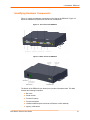
Identifying Hardware Components
Figure 3-1 shows the hardware components on the front of the EDS4100. Figure 3-2
shows the hardware components on the back of the EDS4100.
Figure 3-1. Front View of the EDS4100
Figure 3-2. Back View of the EDS4100
The bottom of the EDS4100 (not shown) has a product information label. This label
contains the following information:
Bar code
Serial number
Product ID (name)
Product description
Hardware address (also referred to as Ethernet or MAC address)
Agency certifications
EDS Device Servers User Guide
21
3: Installation: EDS4100
Serial Ports
The front of the EDS4100 has four male DB9 serial ports. These ports allow you to
connect up to four standard serial devices:
All four serial ports support RS-232 devices. See Figure 3-3 for pin assignments.
Serial ports 1 and 3 also support RS-422 and RS-485 serial devices.
See Figure 3-4 for pin assignments.
All four serial ports are configured as DTE and support baud rates up to 230,400 baud.
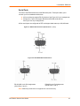
Figure 3-3. RS-232 Serial Port Pins (Serial Ports 1, 2, 3, 4)
Figure 3-4. RS-422/RS-485 Serial Port Pins
RS-422/485 4-wire Pin Assignments
(Serial Ports 1 and 3)
RS-485 2-wire Pin Assignments
(Serial Ports 1 and 3)
Note: Multi-drop connections are supported in 2-wire mode only.
EDS Device Servers User Guide
22
3: Installation: EDS4100
Ethernet Port
The back panel of the EDS4100 provides an RJ45 Ethernet port. This port can connect to
an Ethernet (10 Mbps) or Fast Ethernet (100 Mbps) network. The Speed LED on the
back of the EDS4100 shows the connection of the attached Ethernet network. The
EDS4100 can be configured to operate at a fixed Ethernet speed and duplex mode (halfor full-duplex) or auto-negotiate the connection to the Ethernet network.
Terminal Block Connector
The back of the EDS4100 has a terminal block screw connector for attaching to an
appropriate power source, such as those used in automation and manufacturing
industries. The terminal block connector supports a power range from 42 VDC to
56 VDC. It can be used with the EDS4100’s barrel power connector and PoE capabilities
as a redundant power source to the unit.
Figure 3-5. Terminal Block Connector Pin Assignments
Pin
Signal
Top
V+
Middle
V-
Bottom
Ground
LEDs
Light-emitting diodes (LEDs) on the front and back panels show status information.
Back panel. Each serial port has a Transmit and a Receive LED. The Ethernet
connector has Speed and Activity LEDs. In addition, the back panel has a Power
LED and a Status LED.
Front panel. The front panel has a green Power LED.
The table below describes the LEDs on the back of the EDS4100.
Figure 3-6 .Back Panel LEDs
LED
Description
Transmit (green)
Blinking = EDS is transmitting data on the serial port.
Receive (yellow)
Blinking = EDS is receiving data on the serial port.
Power (green)
On = EDS is receiving power.
Status (yellow)
Fast blink = initial startup (loading OS).
Slow blink (once per second) = operating system startup.
On = unit has finished booting.
Speed (yellow)
On = EDS is connected to a 100 Mbps Fast Ethernet network.
Off = EDS is connected to a 10 Mbps Ethernet network.
Activity (green)
EDS Device Servers User Guide
Blink = EDS is sending data to or receiving data from the Ethernet
network.
23
3: Installation: EDS4100
Reset Button
The reset button is on the back of the EDS4100, to the left of the power connector.
Pressing this button reboots the EDS4100 and terminates all data activity occurring on
the serial and Ethernet ports.
Physically Installing the EDS4100
Finding a Suitable Location
Place the EDS4100 on a flat horizontal or vertical surface. The EDS4100 comes
with mounting brackets installed for vertically mounting the unit, for example, on
a wall.
If using AC power, avoid outlets controlled by a wall switch.
Connecting the EDS4100
Observe the following guidelines when attaching serial devices:
All four EDS4100 serial ports support RS-232 devices.
Alternatively, ports 1 and 3 support RS-422/485 devices.
To connect an EDS4100 serial port to another DTE device, use a null modem
cable.
To connect the EDS4100 serial port to a DCE device, use a straight-through
(modem) cable.
To connect the EDS4100 to one or more serial devices, use the following procedure.
Note: We recommend you power off the serial devices that will be connected to
the EDS4100.
1. For each serial device you want to connect, attach a serial cable between the
EDS4100 and your serial device.
2. Connect an Ethernet cable between the EDS4100 Ethernet port and your Ethernet
network.
3. Use one or more of the following methods to power-up the EDS4100:
PoE method: Power is supplied to the EDS4100 over the Ethernet cable by
either an Ethernet switch or a midspan device.
Barrel power connector: Insert the round end of the supplied power cord into
the barrel power connector on the back of the EDS4100. Plug the other end into
an AC wall outlet. The barrel power connector supports a power range of 9 to 30
VDC.
Terminal block connector: Attach the power source to the terminal block
connector on the back of the EDS4100. The terminal block connector supports a
power range of 42 VDC to 56 VDC.
EDS Device Servers User Guide
24
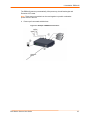
3: Installation: EDS4100
The EDS4100 powers up automatically. After power-up, the self-test begins and
Evolution OS™ starts.
Note: These power-up methods can be used together to provide a redundant
power source to the unit.
4. Power up all connected serial devices.
Figure 3-7. Example of EDS4100 Connections
EDS Device Servers User Guide
25
4: Installation: EDS8PR, EDS16PR and EDS32PR
This chapter describes how to install the EDS8PR, EDS16PR and EDS32PR device
servers.
Package Contents
Your EDS package includes the following items:
One EDS device server (EDS8PR, EDS16PR or EDS32PR)
One RJ45-to-DB9F serial cable
One product CD that includes this User Guide, the Command Reference, and the
Quick Start guide.
A printed Quick Start guide
Your package may also include a power supply.
User-Supplied Items
To complete your EDS8/16/32PR installation, you need the following items:
RS-232 serial devices that require network connectivity. Each EDS8/16/32PR
serial port supports a directly connected RS-232 serial device.
A serial cable for each serial device to be connected to the EDS8/16/32PR. All
devices attached to the device ports support the RS-232C (EIA-232) standard.
Category 5 cabling with RJ45 connections is used for the device port
connections.
Note: To connect an EDS8/16/32PR serial port to a DTE device, you
need a DTE cable, such as the one supplied in your EDS8/16/32PR
package, or an RJ45 patch cable and DTE adapter. To connect the
EDS8/16/32PR serial port to a DCE device, you need a DCE (modem)
cable, or an RJ45 patch cable and DTE adapter. For a list of the
Lantronix cables and adapters you can use with the EDS8/16/32PR, see
E: Lantronix Cables and Adapters.
An available connection to your Ethernet network and an Ethernet cable.
A working power outlet if the unit will be powered from an AC outlet.
EDS Device Servers User Guide
26
4: Installation: EDS8PR, EDS16PR and EDS32PR
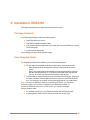
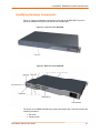
Identifying Hardware Components
Figure 3-1 shows the hardware components on the front of the EDS16PR. Figure 3-2
shows the hardware components on the back of the EDS16PR.
Figure 4-1. Front View of the EDS16PR
Figure 4-2. Back View of the EDS16PR
The bottom of the EDS8/16/32PR has a product information label. This label contains the
following information:
Bar code
Serial number
EDS Device Servers User Guide
27
4: Installation: EDS8PR, EDS16PR and EDS32PR
Product ID (name)
Product description
Hardware address (also referred to as Ethernet or MAC address)
Agency certifications
Serial Ports
The EDS8PR has 8 serial ports, the EDS16PR has 16 serial ports, and the EDS32PR
has 32 serial ports. All serial ports are configured as DTE and support baud rates up to
230,400 baud.
Figure 4-3. RJ45 Serial Port
Ethernet Port
The back panel of the EDS8/16/32PR provides an RJ45 Ethernet port. This port can
connect to an Ethernet (10 Mbps) or Fast Ethernet (100 Mbps) network. The Speed LED
on the back of the EDS8/16/32PR shows the connection of the attached Ethernet
network. The EDS8/16/32PR can be configured to operate at a fixed Ethernet speed and
duplex mode (half- or full-duplex) or auto-negotiate the connection to the Ethernet
network.
LEDs
Light-emitting diodes (LEDs) on the front and back panels show status information.
Back panel. Each serial port has a Transmit and a Receive LED. The Ethernet
connector has a Speed and an Activity LEDs. In addition, the back panel has a
Power LED and a Status LED.
Front panel. The front panel has a green Power LED.
The table below describes the LEDs on the back of the EDS.
Back Panel LEDs
LED
Description
Transmit (green)
Blinking = EDS is transmitting data on the serial port.
Receive (yellow)
Blinking = EDS is receiving data on the serial port.
EDS Device Servers User Guide
28
4: Installation: EDS8PR, EDS16PR and EDS32PR
LED
Description
Power (green)
On = EDS is receiving power.
Status (yellow)
Fast blink = initial startup (loading OS).
Slow blink (once per second) = operating system startup.
On = unit has finished booting.
Speed (yellow)
On = EDS is connected to a 100 Mbps Fast Ethernet network.
Off = EDS is connected to a 10 Mbps Ethernet network.
Activity (green)
Blink = EDS is sending data to or receiving data from the Ethernet
network.
Reset Button
The reset button is on the back of the EDS8/16/32PR, to the left of the power connector.
Pressing this button for 2-to-3 seconds reboots the EDS8/16/32PR and terminates all
data activity occurring on the serial and Ethernet ports.
Physically Installing the EDS8/16/32PR
Finding a Suitable Location
You can install the EDS8/16/32PR either in an EIA-standard 19-inch rack (1U
tall) or as a desktop unit.
If using AC power, avoid outlets controlled by a wall switch.
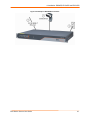
Connecting the EDS8/16/32PR
All serial ports support RS-232 devices.
To connect the EDS8/16/32PR to one or more serial devices, use the following
procedure:
Note: We recommend you power off the serial devices that will be connected to
the EDS8/16/32PR.
1. For each serial device you want to connect, attach a CAT 5 serial cable between the
EDS8/16/32PR and your serial device. For a list of cables and adapters you can use
with the EDS8/16/32PR, see E: Lantronix Cables and Adapters.
2. Connect an Ethernet cable between the EDS8/16/32PR Ethernet port and your
Ethernet network.
3. Insert the supplied power cord into the power connector on the back of the
EDS8/16/32PR. Plug the other end into an AC wall outlet. After power-up, the selftest begins.
4. Power up all connected serial devices.
EDS Device Servers User Guide
29
4: Installation: EDS8PR, EDS16PR and EDS32PR
Figure 4-4. Example of EDS16PR Connections
EDS Device Servers User Guide
30
5: Getting Started
Using DeviceInstaller
The product CD included with your EDS package includes a program called
DeviceInstaller. This program lets you view the properties of the EDS and launch EDS
configuration methods.
Note: You can also assign an IP address and other basic network settings. For
instructions, see the online Help.
Starting DeviceInstaller
Follow the prompts to install DeviceInstaller.
To run DeviceInstaller:
1. From the Windows Start menu, click StartÆPrograms, LantronixÆ
DeviceInstallerÆDeviceInstaller.
2. Click the EDS folder. The list of Lantronix EDS devices available displays.
3. Expand the list by clicking the + symbol next to the icon for the desired EDS model.
4. To view the configuration of the EDS, select the unit by clicking its IP address.
EDS Device Servers User Guide
31
5: Getting Started
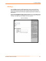
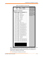
Figure 5-1. Lantronix DeviceInstaller
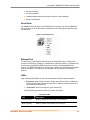
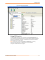
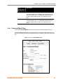
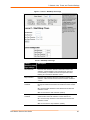
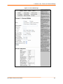
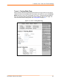
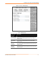
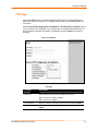
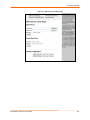
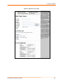
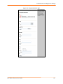
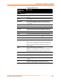
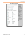
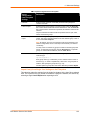
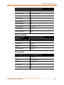
Viewing EDS Properties
To view the EDS’s properties, in the right window, click the Device Details tab. The
current properties for the EDS display. Figure 5-2 lists the EDS properties and whether
they are user configurable or read only. The properties of the other EDS models are
similar except for the number of ports.
Note: On this screen, you can change Group and Comments. You can only
view the remaining properties. To change them, use one of the EDS
configuration methods described on page 34.
EDS Device Servers User Guide
32
5: Getting Started
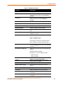
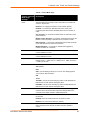
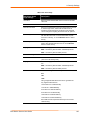
Figure 5-2. EDS4100 Properties
Property
Description
Name*
Displays the name of the EDS, if configured.
Group*
Enter a group to categorize the EDS. Double-click
on the field, enter the value, and press Enter to
complete.
Comments
Enter comments for the EDS. Double-click on the
field, type in the value, and press Enter to
complete.
Device Family
Displays the EDS’s device family type as EDS.
Type
Displays the device type as EDS.
ID
Displays the EDS’s ID embedded within the box.
Hardware Address
Displays the EDS’s hardware address.
Firmware Version
Displays the firmware currently installed on the
EDS.
Extended Version
Displays the full version of firmware currently
installed on the UDS.
Online Status
Displays the EDS status.
Online = the EDS is online.
Offline = the EDS is offline.
Unreachable = the EDS is on a different subnet.
Busy = the EDS is currently performing a task.
IP Address
Displays the EDS’s current IP address. To change
it, click the Assign IP button on the DeviceInstaller
menu bar.
IP Address was Obtained
Displays the method by which the IP address was
obtained:
Statically (assigned manually)
Dynamically = one of the following is True:
Obtain via DHCP
Obtain via BOOTP
Subnet Mask
Gateway
Number of Ports
Displays the subnet mask specifying the network
segment on which the EDS resides.
Displays the IP address of the router of this
network. There is no default.
Displays the number of ports on this EDS.
Supports Email Triggers
True indicates that the EDS supports email
triggers.
Telnet Enabled
Displays whether Telnet is enabled on this EDS.
Telnet Port
Displays the EDS’s port for Telnet sessions.
Web Enabled
Displays whether Web Manager access is enabled
on this EDS.
Web Port
Displays the EDS’s port for Web Manager
configuration.
EDS Device Servers User Guide
33
5: Getting Started
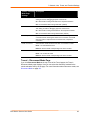
Property
Description
Maximum Baud Rate
Supported
Displays the EDS’s maximum baud rate.
Firmware Upgradeable
Displays True if the EDS firmware is upgradeable.
Note: The EDS may not be operating at this rate.
*Note: These parameters are stored on the computer running DeviceInstaller.
Configuration Methods
When your EDS boots for the first time, it automatically loads its factory-default
configuration settings. For a list of the factory-default configuration settings, see
A: Factory Default Configuration.
For convenience, there are three ways to configure the EDS.
Using the Web Manager interface
Using the CLI through a SSH/Telnet session or an EDS8/16/32PR serial port.
Using the XML interface
These unified configuration methods provide access to all features, giving you the same
level of control over the EDS8/16/32PR regardless of the configuration method you
choose.
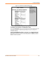
Configuring from the Web Manager Interface
With this method, you can use a Web browser to configure the EDS using a Web-based
graphical point-and-click interface. The advantages to this method are ease of use and
location independence. With this method, you can configure the EDS from any location
that has access to a Web browser and the Internet.
Configuring via an SSH/Telnet Session or Serial Port Using the
CLI
The EDS provides a command-line interface (CLI) designed to enable the configuration
and systems management functions that can also be performed through the Web
Manager and XML interfaces. To configure the EDS using the CLI, you must either start
an SSH or Telnet session or use a terminal or a computer attached to one of the EDS
serial ports or the console port on the EDS8/16/32PR.
The difference between the SSH/Telnet and serial interfaces is the physical connection
paths to the EDS. With an SSH/Telnet session, you can configure the unit without having
to be in the same location as the EDS. The serial-interface method, however, requires a
terminal or computer to be attached to an available EDS serial port. This means the
terminal or computer must be in the same location as the EDS.
Note: Before using SSH, you must first load or generate RSA or DSA keys.
For more information, see the EDS Command Reference on the product CD or the
Lantronix web site (www.lantronix.com).
EDS Device Servers User Guide
34
5: Getting Started
Configuring from the XML Interface
The EDS also provides an XML interface that can be used to perform configuration and
systems-management functions. This configuration method lets you automate the
configuration process using XML configuration files. This method is particularly
convenient if you have multiple EDS device servers that will use the same configuration
settings, because you can define a configuration profile that can be imported by, and
shared among, your other EDS device servers.
For more information, see the EDS Command Reference on the product CD or the
Lantronix web site (www.lantronix.com).
EDS Device Servers User Guide
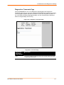
35
6: Configuration Using the Web Manager
This chapter describes how to configure the EDS using the Web Manager, Lantronix’s
browser-based configuration tool. The unit’s configuration is stored in nonvolatile memory
and retained without power. All changes take effect immediately, unless otherwise noted.
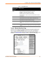
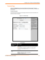
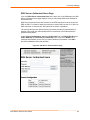
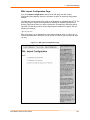
Accessing the Web Manager through a Web Browser
The following procedure describes how to log into the EDS using a standard Web
browser.
Note: Alternatively, access the Web Manager by selecting the Web
Configuration tab from DeviceInstaller (see Viewing EDS Properties on
page 32).
To access Web Manager:
1. Open a standard Web browser such as Netscape Navigator 6.x and later, Internet
Explorer 5.5. and later, Mozilla Suite, Mozilla Firefox, or Opera.
2. Enter the IP address of the EDS in the address bar. The EDS’s built-in security
requires you to log in with your user name and password.
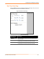
Figure 6-1. Prompt for User Name and Password
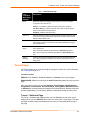
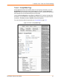
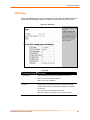
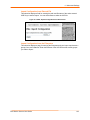
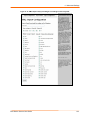
3. Enter your user name and password in the appropriate fields. The Device Status
page displays (see Figure 6-2). This page is the Web Manager home page.
EDS Device Servers User Guide
36
6: Configuration Using the Web Manager
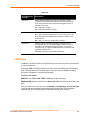
Note: The factory-default user name is admin and the factory-default password
is PASS. After you log in to the Web Manager, we recommend you use the FTP
page to change the default FTP password (see page 79), the HTTP
Authentication Page to change the HTTP authentication password (see page 85),
and the Command Line Interface Configuration Page to change the CLI
password (see page 129).
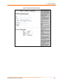
Figure 6-2. Web Manager Device Status Page
EDS Device Servers User Guide
37
6: Configuration Using the Web Manager
Navigating Through the Web Manager
The Web Manager provides an intuitive point-and-click interface. A menu bar at the left
side of each page provides links you can click to navigate from one page to another.
Some pages are read-only, while others let you change configuration settings.
Note: There may be times when you must reboot the EDS for the new
configuration settings to take effect. The chapters that follow indicate when a
change requires a reboot.
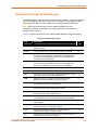
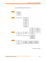
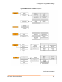
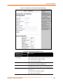
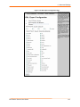
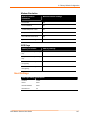
Figure 6-6 shows the structure of the multilevel Web Manager configuration pages.
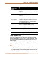
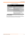
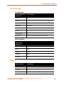
Summary of Web Manager Pages
Page
Description
See
Page
Status
Displays EDS product information and network, line, and
tunneling settings.
47
Network
Lets you configure the current network interface on the EDS.
48
Line
Displays statistics and lets you change the current configuration
and Command mode settings of 4 serial lines for the EDS4100,
8 tunnels for the EDS8PR,16 serial lines for the EDS16PR, and
32 serial lines for the EDS32PR.
51
Tunnel
Displays and lets you change the current configuration settings for
up to 4 tunnels for the EDS4100, 8 tunnels for the EDS8PR, 16
tunnels for the EDS16PR, and 32 tunnels for the EDS32PR.
56
Terminal
Displays and lets you change current settings for a terminal.
72
Host
Displays and lets you change settings for a host on the network.
73
DNS
Displays the current configuration of the DNS subsystem and lets
you change primary and secondary DNS servers.
76
SNMP
Displays and lets you change the current Simple Network
Management Protocol (SNMP) configuration settings.
77
FTP
Displays statistics and lets you change the current configuration
for the File Transfer Protocol (FTP) server.
79
TFTP
Displays statistics and lets you change the current configuration
for the Trivial File Transfer Protocol (TFTP) server.
80
Syslog
Lets you specify the severity of events to log and the server and
ports to which the syslog should be sent.
81
HTTP
Displays HyperText Transfer Protocol (HTTP) statistics and lets
you change the current configuration and authentication settings.
81
RSS
Displays and lets you change current Really Simple Syndication
(RSS) settings.
88
CLI
Displays Command Line Interface (CLI) statistics and lets you
change the current CLI configuration settings.
89
Email
Displays email statistics and lets you clear the email log,
configure email settings, and send an email.
125
LPD
Displays LPD (Line Printer Daemon) Queue statistics and lets you
configure the LPD and print a test page.
89
EDS Device Servers User Guide
38
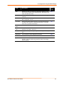
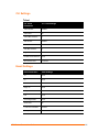
6: Configuration Using the Web Manager
Page
Description
See
Page
SSH
Displays and lets you change the configuration settings for SSH
server host keys, SSH server authorized users, SSH client known
hosts, and SSH client users.
125
SSL
Lets you upload an existing certificate or create a new self-signed
certificate.
101
XML
Lets you export XML configuration and status records, and import
XML configuration records.
131
Filesystem
Displays filesystem statistics and lets you browse the filesystem
to create a file or directory, upload files using HTTP, copy a file,
move a file, or perform TFTP actions.
105
Protocol
Stack
Lets you perform lower level network stack-specific activities.
136
IP Address
Filter
Lets you specify all the IP addresses and subnets that are
allowed to send data to this device.
110
Query Port
Displays and lets you change configuration settings for the query
port.
109
Diagnostics
Lets you perform various diagnostic procedures.
105
RTC
Displays and lets you set the real time clock.
122
System
Lets you reboot the EDS, restore factory defaults, upload new
firmware, change the EDS’s long and short names, and change
the time setting.
123
EDS Device Servers User Guide
39
6: Configuration Using the Web Manager
Figure 6-3. Web Manager Menu Structure (1 of 5)
(continued on next page)
EDS Device Servers User Guide
40
6: Configuration Using the Web Manager
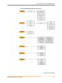
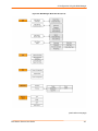
Figure 6-4. Web Manager Menu Structure (2 of 5)
(continued on next page)
EDS Device Servers User Guide
41
6: Configuration Using the Web Manager
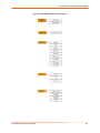
Figure 6-5. Web Manager Menu Structure (3 of 5)
(continued on next page)
EDS Device Servers User Guide
42
6: Configuration Using the Web Manager
Figure 6-6. Web Manager Menu Structure (4 of 5)
(continued on next page)
EDS Device Servers User Guide
43
6: Configuration Using the Web Manager
Figure 6-7. Web Manager Menu Structure (5 of 5)
EDS Device Servers User Guide
44
6: Configuration Using the Web Manager
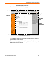
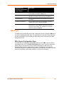
Understanding the Web Manager Pages
Figure 6-8 shows the areas of the Web Manager page.
Figure 6-8. Components of the Web Manager Page
Header
Entry Area
Menu Bar
Information
Area
Current
Configuration
Footer
The header always displays at the top of the page. The header information remains the
same regardless of the page displayed.
The menu bar always displays at the left side of the page, regardless of the page
displayed. The menu bar lists the names of the pages available in the Web Manager. To
display a page, click it in the menu bar.
EDS Device Servers User Guide
45
6: Configuration Using the Web Manager
Figure 6-9. EDS Menu
When you click the name of a page in the menu bar, the page displays in the main area.
The main area of most pages is divided into two sections:
The top section lets you select or enter new configuration settings. After you
change settings, click the Submit button to apply the change. Some settings
require the EDS to be rebooted before the settings take effect. Those settings
are identified in the appropriate sections in this chapter.
The bottom section shows the current configuration.
The information area shows information or instructions associated with the page.
The footer displays at the bottom of the page. It contains copyright information and a link
to the Lantronix home page.
EDS Device Servers User Guide
46
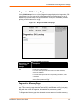
6: Configuration Using the Web Manager
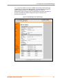
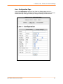
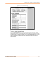
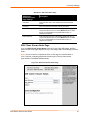
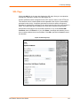
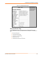
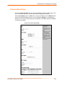
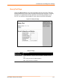
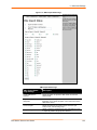
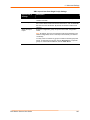
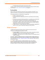
Device Status Page
The Device Status page is the first page that displays when you log into the Web
Manager. It also displays when you click the Status link in the menu bar. This read-only
page shows the EDS product information, network settings, line settings, and tunneling
settings.
Figure 6-10. Device Status Page (EDS4100)
EDS Device Servers User Guide
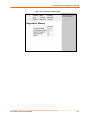
47
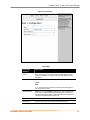
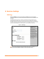
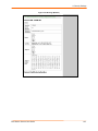
7: Network, Line, Tunnel, and Terminal Settings
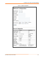
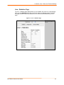
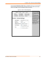
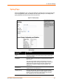
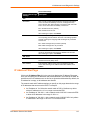
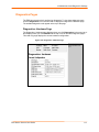
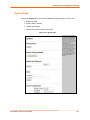
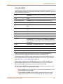
Network Configuration Page
Clicking the Network link in the menu bar displays the Network Configuration page. Here
you can change the following EDS network configuration settings:
BOOTP and DHCP client
IP address, network mask, and gateway
MAC address
Hostname and domain
DHCP client ID
Ethernet transmission speed
EDS Device Servers User Guide
48
7: Network, Line, Tunnel, and Terminal Settings
Figure 7-1. Network Configuration
EDS Device Servers User Guide
49
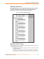
7: Network, Line, Tunnel, and Terminal Settings
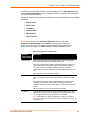
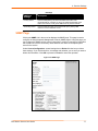
The bottom part of this page shows the current configuration. The After Reboot column
in the Current Configuration section of this page shows the settings that will take effect
the next time the EDS reboots.
Changes to the following settings require the EDS to be rebooted before the new settings
take effect:
BOOTP Client
DHCP Client
IP Address
Network Mask
MAC Address
DHCP Client ID
Notes: Some settings in the Current Configuration section, such as IP
Address and Network Mask have a Delete link you can click to delete the
setting. If you click this link, a warning message asks whether you are sure you
want to delete the setting. Click OK to delete the setting or Cancel to keep it.
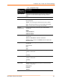
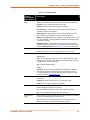
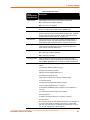
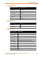
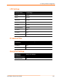
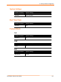
Network Configuration Page Settings
Network
Configuration
Page Settings
Description
BOOTP Client
Select whether the EDS should send BOOTP requests. Changing this
value requires the EDS to be rebooted. Choices are:
On = EDS sends BOOTP requests on a DHCP-managed network. This
setting overrides the configured IP address, network mask, gateway,
host name, and domain settings. If DHCP is set to On, the EDS
automatically uses DHCP, regardless of whether BOOTP Client is set to
On.
Off = EDS does not send BOOTP requests.
DHCP Client
Select whether the EDS IP address is automatically assigned by a DHCP
server. Changing this value requires the EDS to be rebooted. Choices
are:
On = EDS receives its IP address automatically from a DHCP server,
regardless of the BOOTP Client setting. This setting overrides the
configured IP address, network mask, gateway, host name, and domain
settings.
Off = EDS does not receive its IP address automatically.
IP Address
Enter the EDS static IP address. The IP address consists of four octets
separated by a period and is used if BOOTP and DHCP are both set to
Off. Changing this value requires the EDS to be rebooted.
Note: When DHCP is enabled, the EDS tries to obtain an IP address
from DHCP. If it cannot, the EDS uses an Auto IP address in the range of
169.254.xxx.xxx.
EDS Device Servers User Guide
50
7: Network, Line, Tunnel, and Terminal Settings
Network
Configuration
Page Settings
Description
Network Mask
Enter the EDS subnet mask. The subnet mask consists of four octets
separated by a period. Changing this value requires the EDS to be
rebooted.
Note: When DHCP is enabled, the EDS tries to obtain a network mask
from DHCP. If it cannot, the EDS uses a network mask of 255.255.0.0.
Gateway
Enter the router IP address from the local LAN the EDS is on. The
address consists of four octets separated by a period.
MAC Address
Enter the EDS MAC address. Default is factory set. Changing this value
may cause unexpected results. Changing this value requires the EDS to
be rebooted.
Hostname
Enter the EDS host name. The host name can be up to 31 characters
with no spaces.
Domain
Enter the EDS domain name.
DHCP Client ID
Enter a DHCP ID if used by the DHCP server. Changing this value
requires the EDS to be rebooted.
Ethernet Link
Select the Ethernet link speed. Default is Auto.
Line Settings Pages
The Line Settings page displays the status and statistics for each of the serial lines
(ports). This page also lets you change the character format and command mode settings
for the serial lines.
To select a line:
EDS4100: Click Line 1, Line 2, Line 3, or Line 4 at the top of the page.
EDS8/16/32PR: Select the line from the Select Line drop-down list at the top of the
page.
After you select a serial line, you can click Statistics, Configuration, or Command
Mode to view and change the settings of the selected serial line. Because all serial lines
operate independently, you can specify different configuration settings for each line.
EDS Device Servers User Guide
51
7: Network, Line, Tunnel, and Terminal Settings
Line – Statistics Page
The Line – Statistics page displays when you click Line in the menu bar. It also displays
when you click Statistics at the top of one of the other Line Settings pages. This readonly page shows the status and statistics for the serial line selected at the top of this
page.
Figure 7-2. Line – Statistics Page
EDS Device Servers User Guide
52
7: Network, Line, Tunnel, and Terminal Settings
Line - Configuration Page
If you click Configuration at the top of one of the Line Settings pages, the Line –
Configuration page displays. This page shows the configuration settings for the serial line
selected at the top of the page and lets you change the settings for that serial line.
Figure 7-3. Line – Configuration Page
EDS Device Servers User Guide
53
7: Network, Line, Tunnel, and Terminal Settings
Line – Configuration Page
Line –
Configuration
Page Settings
Description
Name (optional)
Enter a name for the serial port. The name may have up to 25
characters. Lines with names display in the Login Connect
Menu.
Status
Select to enable or disable the selected EDS serial port.
Protocol
From the drop-down list, select the type of protocol used on the
line. Choices are:
Tunnel = for connecting two serial devices across a network.
LPD = (Line Printer Daemon) for communicating with a printer.
None = use only with CLI and Login Connect Menu.
Interface
(EDS4100 only)
From the drop-down list, select the type of serial interface.
Choices are:
RS232
RS485 Half-Duplex
RS485 Full-Duplex
Baud Rate
Select the baud rate for the currently selected serial port.
Choices are:
300 baud to 230,400 baud. Default is 9600 baud.
Custom = lets you enter in the Custom text box a speed other
than those shown.
Parity
Select the parity used by the currently selected serial line.
Choices are:
None (default)
Even
Odd
Data Bits
Select the number of data bits used by the currently selected
serial line. Choices are:
7
8 (default)
Stop Bits
Select the number of stop bits used by the currently selected
serial line. Choices are:
1 (default)
2
Flow Control
Select the flow control method used by the currently selected
serial line. Choices are:
None(default)
Hardware
Software
EDS Device Servers User Guide
54
7: Network, Line, Tunnel, and Terminal Settings
Line –
Configuration
Page Settings
Description
Xon char
Character to use to initiate a flow of data.
When Flow Control is set to Software, specify Xon char. Prefix
a decimal character with \ or a hexadecimal character with 0x, or
provide a single printable character. The default Xon char is
0x11.
When Flow Control is set to Software, specify Xoff char. Prefix
a decimal character with \ or a hexadecimal character with 0x, or
provide a single printable character. The default Xoff char is
0x13.
Xoff char
Line – Command Mode Page
If you click Command Mode at the top of one of the Line Settings pages, the Line –
Command Mode page displays. This page shows the command mode settings for the
serial line selected at the top of the page and lets you change the settings for that serial
line.
Figure 7-4. Line – Command Mode Page
EDS Device Servers User Guide
55
7: Network, Line, Tunnel, and Terminal Settings
Line – Command Mode Page
Line –
Command
Mode Page
Settings
Description
Mode
Select the method of enabling command mode or choose to disable
command mode. Choices are:
Always = immediately enables command mode for the serial line.
Use Serial String = enables command mode when the serial string is
read on the serial line during boot time.
Disabled = Disables command mode.
Wait Time
Enter the maximum number of milliseconds the selected serial line waits
to receive the specific serial string at boot time to enter command mode.
Default is 5000 milliseconds.
Serial String
Enter the serial string that places the serial line into command mode.
After entering a string, use the buttons to indicate whether the string is a
text or binary value.
Echo Serial
String
Select whether the serial line echoes the specified serial string at boot
time. Choices are:
Yes = echoes the characters specified in the Serial String text box.
No = does not echo the characters specified in the Serial String text
box.
Signon
Message
Enter the boot-up signon message to be sent over the serial line at boot
time. After entering the message, select whether the string is a text or
binary value.
Tunnel Pages
The Tunnel pages let you view and configure settings for tunnels. (For more information,
see Tunneling on page 161.)
To select a tunnel:
EDS4100: Click Tunnel 1, Tunnel 2, Tunnel 3, or Tunnel 4 at the top of the page.
EDS8/16/32PR: Select the tunnel from the Select Tunnel drop-down list at the top of the
page.
After you select a tunnel, you can click Statistics, Serial Settings, Start/Stop Chars,
Accept Mode, Connect Mode, Disconnect Mode, Packing Mode, Modem Emulation,
or AES Keys to view and change the settings of the selected tunnel. Because all tunnels
operate independently, you can specify different configuration settings for each tunnel.
Tunnel – Statistics Page
The Tunnel – Statistics page displays when you click Tunnel in the menu bar. It also
displays when you click Statistics at the top of one of the other Tunnel pages. This readonly page shows the status and statistics for the tunnel currently selected at the top of
this page.
EDS Device Servers User Guide
56
7: Network, Line, Tunnel, and Terminal Settings
Figure 7-5. Tunnel - Statistics Page
Tunnel – Serial Settings Page
If you click Serial Settings at the top of one of the Tunnel pages, the Tunnel – Serial
Settings page displays. This page shows the settings for the tunnel selected at the top of
the page and lets you change the settings. If you change the Buffer Size value, the EDS
must be rebooted for the change to take effect. Changing the other values does not
require a reboot.
EDS Device Servers User Guide
57
7: Network, Line, Tunnel, and Terminal Settings
Under Current Configuration, Buffer Size has a Reset link that lets you reset the buffer
size value shown. If you click this link, a message tells you that you will have to reboot
the EDS. Click OK to proceed or Cancel to cancel the operation.
Figure 7-6. Tunnel – Serial Settings Page
EDS Device Servers User Guide
58
7: Network, Line, Tunnel, and Terminal Settings
Tunnel – Serial Settings Page
Tunnel –
Serial
Settings Page
Description
Line Settings
Displays the current serial line settings (set on the Line-Configuration
page.)
Protocol
Displays the currently selected protocol (set on the Line Configuration
page).
Buffer Size
Enter the size of the buffer used to receive data on the serial line.
Range = 1 to 4096 bytes. Default is 2048 bytes. Changing this value
requires the EDS to be rebooted.
Wait for Read
Timeout
Select whether the EDS waits the entire Read Timeout value for incoming
data on the serial line. Waiting occurs even if there is data in the read
buffer ready to be processed. The Read Timeout is ignored only when the
read buffer completely fills with data. Choices are:
Enabled = waits the entire Read Timeout value for incoming data on the
serial line.
Disabled = does not wait the entire Read Timeout value for incoming data
(default).
Read Timeout
Enter the maximum number of milliseconds that the EDS waits for
incoming data on the serial line. Default is 200 milliseconds.
DTR
Select how DTR should be asserted. Choices are:
Asserted while connected = DTR is asserted whenever a connect or an
accept mode tunnel connection is active.
Continuously asserted = DTR is asserted regardless of the type and
status of the connection.
Tunnel – Start/Stop Characters Page
If you click Start/Stop Chars at the top of one of the Tunnel pages, the Tunnel –
Start/Stop Chars page displays. This page shows the start and stop characters used for
the tunnel selected at the top of the page and lets you change the settings for that tunnel.
EDS Device Servers User Guide
59
7: Network, Line, Tunnel, and Terminal Settings
Figure 7-7. Tunnel – Start/Stop Chars Page
Tunnel – Start/Stop Chars Page
Tunnel –
Start/Stop Chars
Page Settings
Description
Start Character
Enter the start character. When this character is read on the
serial line, it either initiates a new connection (for a tunnel in
Connect mode) or enables a tunnel in Accept mode to start
listening for connections. Default is <none>.
Stop Character
Enter the stop character. When this character is read on the
serial line, it disconnects an active tunnel connection. Default is
<none>.
Echo Start
Character
Select whether the start character is forwarded (or “echoed’)
through the selected tunnel when the serial line is read. Choices
are:
On = echo the start character on the selected tunnel when the
serial line is read.
Off = do not echo the start character. (default)
Echo Stop
Character
Select whether the stop character is echoed through the
selected tunnel when the serial line is read. Choices are:
On = echo the stop character on the selected tunnel when the
serial line is read.
Off = do not echo the stop character. (default)
EDS Device Servers User Guide
60
7: Network, Line, Tunnel, and Terminal Settings
Tunnel – Accept Mode Page
Accept Mode determines how the EDS “listens” for an incoming connection. If you click
Accept Mode at the top of one of the Tunnel pages, the Tunnel – Accept Mode page
displays. Here you can select the method for starting a tunnel in Accept mode and select
other settings for the tunnel selected at the top of the page.
Under Current Configuration, Local Port has a Reset link if it has been changed from
the default. If you click this link, a message tells you that your action may stop an active
connection. Click OK to proceed or Cancel to cancel the operation.
For more information about Accept mode, see Accept Mode on page 163.
Figure 7-8. Tunnel – Accept Mode Page
EDS Device Servers User Guide
61
7: Network, Line, Tunnel, and Terminal Settings
Tunnel – Accept Mode Page
Tunnel –
Accept Mode
Page Settings
Description
Mode
Select the method used to start a tunnel in Accept mode. Choices are:
Disabled = do not accept an incoming connection.
Enabled = accept an incoming connection. (default)
Any Character = start waiting for an incoming connection when any
character is read on the serial line.
Start Character = start waiting for an incoming connection when the
start character for the selected tunnel is read on the serial line.
Modem Control Asserted = start waiting for an incoming connection as
long as the Modem Control pin (DSR) is asserted on the serial line until
a connection is made.
Modem Emulation = start waiting for an incoming connection when
triggered by modem emulation AT commands. Connect mode must also
be set to Modem Emulation (see Tunnel – Connect Mode on page 63).
Local Port
Enter the number of the local port used to receive (or listen for) packets.
Default is 10001 for Tunnel 1, 10002 for Tunnel 2, and so forth.
Protocol
Select the protocol to be used on the connection. Choices are:
TCP (default)
SSH = use this setting if security is a concern. When using SSH, both
the SSH Server Host Keys and SSH Server Authorized Users must be
configured. (See SSH on page 158.)
SSL = Secure Socket Layer.
Telnet
TCP/AES = use for secure tunneling between two EDS’s or software
that supports AES such as the Secure Com Port Redirector. Secure
Com Port Redirector is on the CD that came with your EDS or on the
Lantronix Web Site (www.lantronix.com).
Flush Serial Data
Select whether the serial line is flushed when a connection is made.
Choices are:
Enabled = flush the serial line when a connection is made.
Disabled = do not flush the serial line. (default)
Block Serial Data
Select whether incoming serial data should be discarded. This setting is
used for debugging purposes. Choices are:
On = discard all incoming serial data on the respective interface.
Off = do not discard all incoming serial data. (default)
Block Network
Data
Select whether incoming network data should be discarded. This setting
is used for debugging purposes. Choices are:
On = discard all incoming network data on the respective interface.
Off = do not discard all incoming network data. (default)
EDS Device Servers User Guide
62
7: Network, Line, Tunnel, and Terminal Settings
Tunnel –
Accept Mode
Page Settings
Description
TCP Keep Alive
Specify the number of milliseconds the EDS waits during an inactive
connection before checking the status of the connection. If the EDS
does not receive a response from the remote host, it drops that
connection.
Email on Connect
Select whether an email is sent when a connection is made.
None = do not send an email.
Email # = send an email corresponding to the tunnel number.
Email on
Disconnect
Select whether an email corresponding to the tunnel number is sent
when a connection is closed.
None = do not send an email.
Email # = send an email corresponding to the tunnel number.
Password
Enter a password that clients must send to the EDS within 30 seconds
from opening a network connection to enable data transmission.
The password can have up to 31 characters and must contain only
alphanumeric characters and punctuation. When set, the password sent
to the EDS must be terminated with one of the following: (a) 0x10 (LF),
(b) 0x00, (c) 0x13 0x10 (CR LF), or (d) 0x13 0x00.
Prompt for
Password
Indicate whether the user should be prompted for the password upon
connection.
On = prompt for a password upon connection.
Off = do not prompt for a password upon connection.
Tunnel – Connect Mode Page
Connect Mode determines how the EDS initiates a connection to a remote host or device.
If you click Connect Mode at the top of one of the Tunnel pages, the Tunnel – Connect
Mode page displays. Here you can select the method for starting a tunnel in Connect
mode and select other settings for the tunnel selected at the top of the page.
Any configuration changes you make on the displayed page apply to the tunnel you
selected at the top of this page. For example, if Tunnel 1 is selected, any configuration
changes you make apply to tunnel 1.
Under Current Configuration, both Remote Address and Remote Port have a Delete
link that lets you delete the remote address and port number shown. If you click this link,
a message tells you that your action may stop an active connection. Click OK to proceed
or Cancel to cancel the operation.
For more information about Connect mode, see Connect Mode on page 162.
EDS Device Servers User Guide
63
7: Network, Line, Tunnel, and Terminal Settings
Figure 7-9. Connect Mode Page
EDS Device Servers User Guide
64
7: Network, Line, Tunnel, and Terminal Settings
Tunnel – Connect Mode Page
Tunnel – Connect
Mode Page
Settings
Description
Mode
Select the method to be used to start a connection to a remote host
or device. Choices are:
Disabled = an outgoing connection is never started. (default)
Enabled = a connection is attempted until one is made. If the
connection gets disconnected, the EDS retries until a connection is
made.
Any Character = a connection is started when any character is read
on the serial line.
Modem Control Asserted = a connection is attempted as long as the
Modem Control pin (DSR) is asserted until a connection is made.
Start Character = a connection is attempted when the start character
for the selected tunnel is read on the serial line.
Modem Emulation = a connection is started when triggered by
modem emulation AT commands.
Remote Address
Enter the address of the remote host to which the selected tunnel will
connect. Default is <none>.
Remote Port
Enter the number of the remote port to which the selected tunnel will
connect. Default is <none>.
Local Port
Enter the number of the local port that will participate in this tunnel.
Default is Port 1 = 10001, Port 2 = 10002, Port 3 = 10002, and Port 4
= 10004, and so forth.
Protocol
Select the protocol to use on the connection. Choices are:
TCP (default)
UDP
SSH = use this setting if security is a concern. This setting requires
you to enter an SSH username.
SSL
Telnet
TCP/AES = use for secure tunneling by means of TCP between two
EDS devices or other devices that support AES.
UDP/AES = use for secure tunneling by means of UDP between two
EDS devices or other devices that support AES.
Reconnect Timer
Enter the maximum number of milliseconds to wait before trying to
reconnect to the remote host after a previous attempt failed or the
connection was closed. Default is 15000 milliseconds.
Flush Serial Data
Select whether to flush the serial line when a connection is made.
Choices are:
Enabled = flush the serial line when a connection is made.
Disabled = do not flush the serial line. (default)
SSH Username
EDS Device Servers User Guide
If you selected SSH as the protocol for this tunnel, enter the SSH
client user that is to be used for the SSH connection. Default is
<none>.
65
7: Network, Line, Tunnel, and Terminal Settings
Tunnel – Connect
Mode Page
Settings
Description
Block Serial Data
Select whether incoming block serial data should be discarded. This
setting is used for debugging purposes. Choices are:
On = discard all incoming serial data on the respective interface.
Off = do not discard all incoming serial data. (default)
Block Network Data
Select whether incoming block network data should be discarded.
This setting is used for debugging purposes. Choices are:
On = discard all incoming network data on the respective interface.
Off = do not discard all incoming network data. (default)
TCP Keep Alive
Specifies the number of milliseconds the EDS waits during an inactive
connection before checking the status of the connection. If the EDS
does not receive a response from the remote host, it drops that
connection.
Email on Connect
Select whether email should be sent when a connection is made.
None = no email should be sent.
Email # = send an email corresponding to the tunnel number.
Email on Disconnect
Select whether email should be sent when a connection is closed.
None = do not send an email
Email # = send an email corresponding to the tunnel number.
Tunnel – Disconnect Mode Page
If you click Disconnect Mode at the top of one of the Tunnel pages, the Tunnel –
Disconnect Mode page displays. Here you can select the disconnect method for the
tunnel selected at the top of the page. For more information about Disconnect mode, see
Disconnect Mode on page 163.
EDS Device Servers User Guide
66
7: Network, Line, Tunnel, and Terminal Settings
Figure 7-10. Tunnel – Disconnect Mode Page
Tunnel – Disconnect Mode Page
Tunnel –
Disconnect
Mode Page
Settings
Description
Character
Stop
If enabled, an active connection is disconnected when the specified stop
character is read on the serial line.
Modem
Control
If enabled, an active connection is disconnected when the Modem
Control pin (DSR) is de-asserted on the serial line.
Timeout
Enter the idle time, in milliseconds, that must elapse for a connection
before it is disconnected. Enter 0 (zero) to disable (default).
Flush Serial
Data
Select whether the serial line should be flushed when a connection is
disconnected. Choices are:
Enabled = flush the serial line when a connection is disconnected.
Disabled = do not flush the serial line. (default)
EDS Device Servers User Guide
67
7: Network, Line, Tunnel, and Terminal Settings
Tunnel – Packing Mode Page
When tunneling, data can be packed (queued) and sent in large chunks on the network
instead of being sent immediately after being read on the serial line. If you click Packing
Mode at the top of one of the Tunnel pages, the Tunnel – Packing Mode page displays.
Here you can select packing settings for the tunnel selected at the top of the page. For
more information about Packing mode, see Packing Mode on page 164.
Figure 7-11. Tunnel – Packing Mode Page
EDS Device Servers User Guide
68
7: Network, Line, Tunnel, and Terminal Settings
Tunnel – Packing Mode Page
Tunnel – Packing
Mode Page
Settings
Description
Mode
Select the method used to pack data. Choices are:
Disabled = default packing algorithm. (default)
Timeout = data is sent after the timeout elapses.
Send Character = data is sent when the send character is read on
the serial line.
Timeout
Enter the maximum number of milliseconds to wait before sending
queued data across the network. Default is 1000 milliseconds.
Threshold
Enter the queued data limit that, when reached, immediately sends
queued data to the network. Default is 512 bytes.
Send Character
Enter the send character. When this character is read on the serial
line, it forces the queued data to be sent immediately. Default is
<none>.
Trailing Character
Enter the trailing character. This character is inserted into the
outgoing data stream immediately after the send character. Default is
<none>.
Tunnel – Modem Emulation Page
A tunnel in connect mode can be initiated using modem commands incoming from the
serial line. If you click Modem Emulation at the top of one of the Tunnel pages, the
Tunnel – Modem Emulation page displays. Here you can select modem emulation
settings for the tunnel selected at the top of the page. For more information about modem
emulation, see Modem Emulation on page 164.Tunnel – Modem Emulation Page
EDS Device Servers User Guide
69
7: Network, Line, Tunnel, and Terminal Settings
Tunnel – Modem Emulation Page
Tunnel – Modem
Emulation Page
Settings
Description
Echo Pluses
Select whether the modem plus (+) command is echoed (sent).
Choices are:
On = modem pluses are echoed.
Off = modem pluses are not echoed. (default)
Echo Commands
Select whether modem commands are echoed on the serial line.
Choices are:
On = modem commands are echoed. (default)
Off = modem commands are not echoed.
Verbose Response
Codes
Select whether modem response (result) codes are sent on the
serial line. Choices are:
On = modem responses are sent on the serial line. (default)
Off = modem responses are not sent.
Response Codes
Select whether modem response (result) codes sent on the serial
line take the form of words or numbers. Choices are:
Text = modem responses are sent as words. (default)
Numeric = modem responses are sent as numbers.
Error Unknown
Commands
Select whether an ERROR or OK response is sent in reply to
unrecognized AT commands. Choices are:
On = ERROR is returned for unrecognized AT commands.
Off = OK is returned for unrecognized AT commands. (default)
Connect String
If required, enter a customized string that is sent along with the
CONNECT response code. Default is <none>.
Tunnel – AES Keys Page
Four Advanced Encryption Standard (AES) Encryption Keys are used for tunneling.
Connect mode and Accept mode contain their own sets of keys. One key is used for
encrypting outgoing data and another key is used for decrypting incoming data. These
AES keys are fixed at 16 bytes. Any keys entered that are less than 16 bytes long are
padded with zeroes.
If you click AES Keys at the top of one of the Tunnel pages, the Tunnel – AES Keys
page displays. Here you can enter key data as text or binary values for the tunnel
selected at the top of the page. Binary values are a string of characters representing
hexadecimal or decimal values.
Notes:
Keys are shared secret keys that must be known by both sides of the connection
and kept secret.
Tunneling using AES encryption uses a non-standard protocol and shared keys,
making it not very secure. The EDS also supports SSH as an alternative method
of secure tunneling. SSH tunneling has the advantage of not using shared keys.
EDS Device Servers User Guide
70
7: Network, Line, Tunnel, and Terminal Settings
Figure 7-12. Tunnel – AES Keys Page
Tunnel – AES Keys Page
Tunnel – AES
Keys Page
Settings
Description
Accept Mode AES
Keys: Encrypt Key
Enter the AES encrypt key for Accept mode. After entering a value,
select an option to specify whether the value is text or binary.
Default is <none>.
Accept Mode AES
Keys: Decrypt
Key
Enter the AES decrypt key for Accept mode. After entering a value,
select an option to specify whether the value is text or binary.
Default is <none>.
Connect Mode
AES Keys:
Encrypt Key
Enter the AES encrypt key for Connect mode. After entering a
value, select an option to specify whether the value is text or binary.
Default is <none>.
Connect Mode
AES Keys:
Decrypt Key
Enter the AES decrypt key for Connect mode. After entering a
value, select an option to specify whether the value is text or binary.
Default is <none>.
EDS Device Servers User Guide
71
7: Network, Line, Tunnel, and Terminal Settings
Terminal Page
Clicking the Terminal link in the menu bar displays the Terminal page. This page
displays configuration settings for the terminal on a serial line and lets you change them
as necessary.
To select a terminal:
From the drop-down list at the top of the page, select the line that is connected to the
terminal you want to configure.
Figure 7-13. Terminal Page
Terminal Page
Terminal Page
Settings
Description
Terminal Type
Enter text to describe the type of terminal. The text will be sent to a
host via IAC.
Note: IAC means “interpret as command.” It is a way to send
commands over the network such as send break or start
echoing.
Login Connect
Menu
Select the interface to display when the user logs in. Choices are:
Enabled = displays the Login Connect Menu.
Disabled = displays the CLI
EDS Device Servers User Guide
72
7: Network, Line, Tunnel, and Terminal Settings
Terminal Page
Settings
Description
Exit Connect
Menu
Select whether to display a choice for the user to exit the Login
Connect Menu and reach the CLI. Choices are:
Enabled = a choice allows the user to exit to the CLI.
Disabled = there is no exit to the CLI.
Send Break
Enter a Send Break control character, e.g., <control> Y, or blank to
disable.
When the Send Break control character is received from the
network on its way to the serial line, it is not sent to the line;
instead, the line output is forced to be inactive (the break condition).
Break Duration
Enter how long the break should last in milliseconds.
Host Page
Clicking the Host link in the menu bar displays the Host page. This page displays current
settings for a remote host and lets you change these settings.
To select a host:
EDS4100: Click Host 1, Host 2, Host 3, or Host 4 at the top of the page.
EDS8/16/32PR: Select the tunnel from the Select Host drop-down list at the top of the
page.
EDS Device Servers User Guide
73
7: Network, Line, Tunnel, and Terminal Settings
Figure 7-14. Host Page
Host Page
Host Page
Settings
Description
Name
Enter a name for the host. This is the name that displays on the
Login Connect Menu. To leave a host out of the menu, leave this
field blank.
Protocol
Select the protocol to use to connect to the host. Choices are:
Telnet
SSH
Note: SSH keys must be loaded or created on the SSH page for
the SSH protocol to work.
SSH Username
Displays if you selected SSH as the protocol. Enter a username to
select a pre-configured Username/Password/Key (configured on
the SSH: Client Users page), or leave it blank to be prompted for a
username and password at connect time.
Remote Address
Enter an IP address for the host.
Remote Port
Enter the port on the host to which the EDS will connect.
EDS Device Servers User Guide
74
7: Network, Line, Tunnel, and Terminal Settings
Login Connect Menu
An administrator can set up a menu on the EDS for terminal users.
For a terminal attached to serial Line N, set as follows:
Line[N] Protocol = None
Line[N] Command Mode = Always
Terminal[Line N] Login Connect Menu = Enabled.
For Telnet-attached terminals, set:
Terminal [Network] Login Connect Menu = Enabled.
The terminal user will see a menu roughly like this:
Password :
Connection menu: (select by number)
1) Alpha
2) Beta
3) Exit to command line interface
4) Log out
Selection =
The administrator adds destination serial line M to the menu by filling in Line[M] Name.
For this purpose, set:
Line[M] Protocol = None
Line[M] Command Mode = Disabled.
The administrator adds a network destination to the menu by setting up a Host entry for
it. Each named Host entry will appear in the menu.
The administrator adds the Exit to command line interface choice to the menu by
setting:
Terminal[Line N] or Terminal[Network] Exit Connect Menu = Enabled.
The Log out choice is always present.
EDS Device Servers User Guide
75
8: Services Settings
DNS Page
Clicking the DNS link in the menu bar displays the DNS page. This page displays
configuration settings for the domain name system (DNS) and lets you change them as
necessary.
The DNS page also shows any contents in the DNS cache. When a DNS name is
resolved using a forward lookup, the results are stored in the DNS cache temporarily.
The EDS consults this cache when performing forward lookups. Each entry in the cache
is removed automatically after a certain period, or you can delete it manually.
Figure 8-1. DNS Page
Note: If the current configuration shows an address that comes from DHCP or
BOOTP, the new static address overrides it until you reboot the device.
EDS Device Servers User Guide
76
8: Services Settings
DNS Page
DNS Page
Settings
Description
Primary Server
Enter the DNS primary server that maintains the master zone
information/file for a domain. No server is configured with DNS. If the
EDS is set to DHCP, it will get the DNS server by means of DHCP.
Secondary Server
Enter the DNS secondary server that backs up the primary DNS
server for a zone. Default is <none>.
SNMP Page
Clicking the SNMP link in the menu bar displays the SNMP page. This page is used to
configure the Simple Network Management Protocol (SNMP) agent. Using this page, you
can configure the SNMP service to send a trap when it receives a request for information
that contains an incorrect community name and does not match an accepted system
name for the service.
Under Current Configuration, several settings have a Delete link that lets you delete
these settings. If you click these links, a message asks whether you are sure you want to
delete this information. Click OK to proceed or Cancel to cancel the operation.
Figure 8-2. SNMP Page
EDS Device Servers User Guide
77
8: Services Settings
SNMP Page
SNMP Page Settings
Description
SNMP Agent
Select whether SNMP is enabled. Choices are:
On = SNMP is enabled. (default)
Off = SNMP is disabled.
Read Community
Enter the case-sensitive community name from which the
EDS will receive trap messages. Default is public. For
security, the read community name displays as <Configured>
to show that one is enabled.
Write Community
Enter the case-sensitive community name to which the EDS
will send trap messages. Default is private. For security, the
write community name displays as <Configured> to show that
one is enabled.
System Contact
Enter the name of the system contact. No contact is
configured by default.
System Name
Enter the EDS’s name.
System Description
Enter a system description for the EDS.
System Location
Enter the geographic location of the EDS. No location is
configured by default.
Enable Traps
Select whether SNMP cold start trap messages are enabled
at boot. Choices are:
On = SNMP cold start trap messages are enabled at boot
time. (default)
Off = SNMP traps are disabled.
Primary TrapDest IP
Enter the primary SNMP trap host. None set by default.
Secondary TrapDest IP
Enter the secondary SNMP trap host. None set by default.
EDS Device Servers User Guide
78
8: Services Settings
FTP Page
Clicking the FTP link in the menu bar displays the FTP page. This page displays the
current File Transfer Protocol (FTP) connection status and various statistics about the
FTP server.
Under Current FTP Configuration and Statistics, FTP Password has a Reset link that
lets you reset the FTP password. If you click this link, a message asks whether you are
sure you want to reset this information. Click OK to proceed or Cancel to cancel the
operation.
Figure 8-3. FTP Page
FTP Page
FTP Page
Settings
Description
FTP Server
Select whether the FTP server is enabled. Choices are:
On = FTP server is enabled. (default)
Off = FTP server is disabled.
FTP Username
Enter the username required to gain FTP access. Default is admin.
FTP Password
Enter the password associated with the username. Default is
PASS.
EDS Device Servers User Guide
79
8: Services Settings
TFTP Page
Clicking the TFTP link in the menu bar displays the TFTP page. This page displays the
status and various statistics about the Trivial File Transfer Protocol (TFTP) server.
Figure 8-4. TFTP Page
TFTP Page
TFTP Page Settings
Description
TFTP Server
Select whether the TFTP server is enabled. Choices are:
On = TFTP server is enabled. (default)
Off = TFTP server is disabled.
Allow TFTP File
Creation
Select whether the TFTP server can create a file if it does not
already exist. If you enable this feature, it exposes the EDS to
possible Denial-of-Service (DoS) attacks against the filesystem.
Choices are:
On = files can be created by the TFTP server.
Off = files cannot be created by the TFTP server. (default)
EDS Device Servers User Guide
80
8: Services Settings
Syslog Page
Clicking the Syslog link in the menu bar displays the Syslog page. This page shows the
current configuration, status, and statistics for the syslog. Here you can configure the
syslog destination and the severity of the events to log.
Figure 8-5. Syslog Page
Syslog Page
Syslog Page
Settings
Description
Host
Enter the IP address of the remote server to which system logs
are sent for storage.
Local Port
Enter the number of the local port on the EDS to which system
logs are sent.
The system log is always saved to local storage, but it is not
retained through reboots. Saving the system log to a server that
supports remote logging services (see RFC 3164) allows the
administrator to save the complete system log history. The
default is 514.
Remote Port
Enter the number of the port on the remote server that supports
logging services. The default is 514.
Severity to Log
From the drop-down box, select the minimum level of system
message the EDS should log. This setting applies to all syslog
facilities. The drop-down list is in descending order of severity
(e.g., Emergency is more severe than Alert.)
EDS Device Servers User Guide
81
8: Services Settings
HTTP Pages
Clicking the HTTP link in the menu bar displays the HTTP Statistics page. This page has
four links at the top for viewing statistics and for viewing and changing configuration and
authentication settings.
HTTP Statistics Page
The HTTP Statistics page displays when you click HTTP in the menu bar. It also displays
when you click Statistics at the top of one of the other HTTP pages. This read-only page
shows various statistics about the Hyper Text Transfer Protocol (HTTP) server.
Note: The HTTP log is a scrolling log, with the last Max Log Entries lines
cached and viewable. To change the maximum number of entries that can be
viewed, go to the HTTP Configuration page (described on page 82).
Figure 8-6. HTTP Statistics Page
HTTP Configuration Page
If you click Configuration at the top of one of the HTTP pages, the HTTP Configuration
page displays. Here you can change HTTP configuration settings.
Under Current Configuration, Logs has View and Clear links that let you view or clear
the log. If you click View, the log displays. If you click Clear, a message asks whether
you are sure you want to delete this information. Click OK to proceed or Cancel to cancel
the operation.
Note: For help changing the format of the log, see Log Format Directives in the
information area or on page 85.
EDS Device Servers User Guide
82
8: Services Settings
Figure 8-7. HTTP Configuration Page
EDS Device Servers User Guide
83
8: Services Settings
HTTP Configuration Page
HTTP
Configuration
Page Settings
Description
HTTP Server
Select whether the HTTP server is enabled. Choices are:
On = HTTP server is enabled. (default)
Off = HTTP server is disabled.
HTTP Port
Enter the number of the port on which the EDS listens for incoming
HTTP connections from a Web browser. Default is 80.
HTTPS Port
Enter the number of the port on which the EDS listens for incoming
HTTPS connections from a Web browser. Default is 443. The EDS
listens on the HTTPS port only when an SSL certificate has been
configured for the device (see SSL on page 101).
Max Timeout
Enter the maximum number of seconds that the EDS waits for a
request from a client. This value helps prevent Denial of Service
(DoS) attacks against the HTTP Server. Default is 10 seconds.
Max Bytes
Enter the maximum number of bytes allowed in a client request. This
value helps prevent Denial of Service (DoS) attacks against the
HTTP Server. Default is 40960 bytes.
Logging
Select whether the HTTP log is enabled. Choices are:
On = HTTP log is enabled. (default)
Off = HTTP log is disabled.
Max Log Entries
Enter the maximum number of entries that can be cached and
viewed in the HTTP log. The HTTP log is a scrolling log, with only
the last Max Log Entries lines cached and viewable. Default is 50.
Log Format
Enter the format of the HTTP log. The log format directives are as
follows:
%a remote IP address (could be a proxy)
%b bytes sent excluding headers
%B bytes sent excluding headers (0 = '-')
%h remote host (same as '%a')
%{h}i header contents from request (h = header string)
%m request method
%p ephemeral local port value used for request
%q query string (prepend with '?' or empty '-')
%t timestamp HH:MM:SS (same as Apache '%(%H:%M:%S)t' or
'%(%T)t')
%u remote user (could be bogus for 401 status)
%U URL path info
%r first line of request (same as '%m %U%q <version>')
%s return status
The maximum length for each directive is 64 bytes. The exception is
'%r' where each element is limited to 64 bytes (i.e. method, URL
path info, and query string). The default log format string is: %h %t
"%r" %s %B "%{Referer}i" "%{User-Agent}i"
EDS Device Servers User Guide
84
8: Services Settings
HTTP Authentication Page
HTTP Authentication allows you to require usernames and passwords to access specific
web pages or directories on the EDS's built-in web server.
For example, to add web pages to the EDS to control or monitor of a device attached to a
port on the EDS, you can specify the user and password that can access that web page.
If you click Authentication at the top of one of the HTTP pages, the HTTP Authentication
page displays. Here you can change HTTP authentication settings.
Under Current Configuration, URI and Users have a Delete link. If you click Delete, a
message asks whether you are sure you want to delete this information. Click OK to
proceed or Cancel to cancel the operation.
Example:
The following example shows how to add authentication to user-loaded web pages in a
directory called port1control.
1. Create a directory called port1control in the EDS's files system and under the /http
directory (using an FTP client, Windows Explorer, or the EDS Web Manager).
2. Copy the custom web pages to this directory.
3. On the HTTP Authentication page of the EDS Web Manager, add:
A URI of port1control
A Realm of Monitor
An AuthType of Digest
A Username and Password
4. Click the Submit button. The EDS creates a username and password to allow the
user to access all web pages located in the directory port1control in the EDS file
system.
5. You can access the web pages by going to http://<your device>/port/control/ web
server>.
Note: The URI, realm, username, and password are user-specified, freeform
fields. The URI must match the directory created on the EDS file system. The
URI and realm used in the example above are only examples and would typically
be different as specified by the user.
EDS Device Servers User Guide
85
8: Services Settings
Figure 8-8. HTTP Authentication Page
EDS Device Servers User Guide
86
8: Services Settings
HTTP Authentication Page
HTTP
Authentication
Page Settings
Description
URI
Enter the Uniform Resource Identifier (URI) of the resource that will
participate in the authentication process.
Note: To refer to a file resource, the URI must begin with /.
Realm
Enter the domain, or realm, used for HTTP operations.
AuthType
Select an authorization type. Different types of authorization offer
varying levels of security. Choices are (from least to most secure):
None = no authentication necessary.
Basic = encodes passwords using Base64.
Digest = encodes passwords using MD5. (Default)
SSL = page can only be accessed over SSL (no password).
SSL/Basic = page can only be accessed over SSL (encodes
passwords using Base64).
SSL/Digest = page can only be accessed over SSL (encodes
passwords using MD5).
SSL alone does not require a password, but all data transferred to and
from the HTTP Server is encrypted. There is no reason to create an
authentication directive using None, unless you want to override a
parent directive that uses some other AuthType. Multiple users can be
configured within a single authentication directive.
Username
Enter the name of the user who will participate in the authentication.
Default is admin.
Password
Enter the password that will be associated with the username. Default
is PASS.
EDS Device Servers User Guide
87
8: Services Settings
RSS Page
If you click RSS on the menu, the RSS page displays. Here you can specify Really
Simple Syndication (RSS) information. RSS is a way of feeding online content to web
users. Instead of actively searching for EDS configuration changes, RSS feeds allow
viewing of only relevant and new information regarding changes made to the EDS via an
RSS publisher.
Under Current Configuration, Data has View and Clear links. If you click View, the data
displays. If you click Clear, a message asks whether you are sure you want to delete this
information. Click OK to proceed or Cancel to cancel the operation.
Figure 8-9. RSS Page
EDS Device Servers User Guide
88
8: Services Settings
RSS Page
HTTP RSS Page
Settings
Description
RSS Feed
Select whether an RSS feed is enabled or disabled. An RSS
syndication feed is served by the HTTP server. This feed contains
up-to-date information about configuration changes that occur on
the EDS. Choices are:
On = RSS feed is enabled.
Off = RSS feed is disabled. (default)
Persistent
Select whether the RSS feed is persistent. Choices are:
On = data is stored on the filesystem, in the file “/cfg_log.txt.” This
allows feed data to be available across reboots or until the factory
defaults are set.
Off = data is not stored on the filesystem. (default)
Max Entries
Enter the maximum number of log entries. The RSS feed is a
scrolling feed, with only the last Max Entries entries cached and
viewable. To be notified automatically about any configuration
changes that occur, register the RSS feed within your favorite RSS
aggregator. Default is 100.
Each RSS feed entry is prefixed with a timestamp.
LPD Pages
In addition to its other functions, the EDS acts as a print server if a printer is connected to
one of its serial ports.
Clicking the LPD (Line Printer Daemon) link in the menu bar displays the LPD Statistics
page. This page has three links at the top for viewing print queue statistics, changing
print queue configuration, and printing a test page.
To select a line printer:
EDS4100: Click LPD1, LPD2, LPD3, or LPD 4 at the top of the page.
EDS8/16/32PR: Select the LPD from the Select LPD Line drop-down list at the top of the
page.
After you select an LPD line, you can click Statistics, Configuration, or Print Test Page
to view or change the settings of the selected LPD. Because all LPD lines operate
independently, you can specify different configuration settings for each one.
EDS Device Servers User Guide
89
8: Services Settings
LPD Statistics Page
The LPD Statistics page displays when you click LPD in the menu bar. It also displays
when you click Statistics at the top of one of the other LPD pages. This read-only page
shows various statistics about the LPD server.
Figure 8-10. LPD Statistics Page
EDS Device Servers User Guide
90
8: Services Settings
LPD Configuration Page
If you click Configuration at the top of one of the LPD pages, the LPD Configuration
page displays. Here you can change LPD configuration settings.
Figure 8-11. LPD Configuration Page
EDS Device Servers User Guide
91
8: Services Settings
LPD Configuration Page
LPD
Configuration
Page Settings
Description
Banner
Select Enabled to print the banner even if the print job does not
specify to do so. Selected by default.
Binary
Select Enabled for the EDS is to pass the entire file to the printer
unchanged. Otherwise, the EDS passes only valid ascii and valid
control characters to the printer. Valid control characters include the
tab, linefeed, formfeed, backspace, and newline characters. All
others are stripped. Unselected by default.
Start of Job
Select Enabled to print a "start of job" string before sending the print
data.
End of Job
Select Enabled to send an "end of job" string.
Formfeed
Select Enabled to force the printer to advance to the next page at
the end of each print job.
Convert
Newlines
Select Enabled to convert single newlines and carriage returns to
DOS-style line endings.
SOJ String
If Start of Job (above) is enabled, enter the string to be sent to the
printer at the beginning of a print job. The limit is 100 characters.
Indicate whether the string is in text or binary format.
EOJ String
If End of Job (above) is enabled, enter the string to send at the end
of a print job. The limit is 100 characters. Indicate whether the string
is in text or binary format.
Queue Name
To change the name of the print queue, enter a new name. The
name cannot have white space in it and is limited to 31 characters.
EDS Device Servers User Guide
92
9: Security Settings
SSH Pages
Clicking the SSH link in the menu bar displays the SSH Server: Host Keys page. This
page has four links at the top for viewing and changing SSH server host keys, SSH
server authorized keys, SSH client known hosts, and SSH client users.
Note: For more information, see SSH on page 158.
SSH Server: Host Keys Page
The SSH Server: Host Keys page displays when you click SSH in the menu bar. It also
displays when you click SSH Server: Host Keys at the top of one of the other SSH
pages. Here you can generate new keys or upload files containing the keys.
SSH server private and public host keys are used by all applications that play the role of
an SSH server, specifically the CLI and Accept mode tunneling. These keys can be
created elsewhere and uploaded to the device, or generated on the device.
Under Current Configuration, Public RSA Key and Public DSA Key have View and
Delete links if these keys have been created. If you click View, the key displays. If you
click Delete, a message asks whether you are sure you want to delete this information.
Click OK to proceed or Cancel to cancel the operation. For security reasons, you cannot
view the private keys.
EDS Device Servers User Guide
93
9: Security Settings
Figure 9-1. SSH Server: Host Keys Page
EDS Device Servers User Guide
94
9: Security Settings
SSH Server: Host Keys Page
SSH Server: Host
Keys Page Settings
Description
Upload Keys
Private Key
Enter the path and name of the existing private key you want to
upload or use the Browse button to select the key. Be sure the
private key will not be compromised in transit. This implies the
data is uploaded over some kind of secure private network or
an HTTPS connection.
Note: You can upload keys that have up to 2048-bit key length.
Public Key
Enter the path and name of the existing public key you want to
upload or use the Browse button to select the key.
Key Type
Select a key type to be used. Choices are:
RSA = use this key with SSH1 and SSH2 protocols.
DSA = use this key with the SSH2 protocol.
Create New Keys
Key Type
Select a key type to be used for the new key. Choices are:
RSA = use this key with the SSH1 and SSH2 protocols.
DSA = use this key with the SSH2 protocol.
Bit Size
Select a bit length for the new key. Choices are:
512
768
1024
Using a larger bit size takes more time to generate the key.
Approximate times are:
10 seconds for a 512-bit RSA key
1 minute for a 768-bit RSA key
2 minutes for a 1024-bit RSA key
2 minutes for a 512-bit DSA key
10 minutes for a 768-bit DSA key
15 minutes for a 1024-bit DSA key
Some SSH clients require RSA host keys to be at least 1024
bits long.
EDS Device Servers User Guide
95
9: Security Settings
SSH Server: Authorized Users Page
If you click SSH Server: Authorized Users at the top of one of the SSH pages, the SSH
Server: Authorized Users page displays. Here you can change SSH server settings for
authorized users.
SSH Server Authorized Users are accounts on the EDS that can be used to log into the
EDS via SSH. For instance, these accounts can be used to SSH into the CLI or open an
SSH connection to a device port. Every account must have a password.
The user's public keys are optional and only necessary if public key authentication is
wanted. Using public key authentication allows a connection to be made without the
password being asked.
Under Current Configuration, User has a Delete User link, and Public RSA Key and
Public DSA Key have View Key and Delete Key links. If you click a Delete link, a
message asks whether you are sure you want to delete this information. Click OK to
proceed or Cancel to cancel the operation.
Figure 9-2. SSH Server: Authorized Users Page
EDS Device Servers User Guide
96
9: Security Settings
SSH Server: Authorized Users Page
SSH Server:
Authorized Users
Page Settings
Description
Username
Enter the name of the user authorized to access the SSH
server.
Password
Enter the password associated with the username.
Public RSA Key
Enter the path and name of the existing public RSA key you
want to use with this user or use the Browse button to select
the key. If authentication is successful with the key, no
password is required.
Public DSA Key
Enter the path and name of the existing public DSA key you
want to use with this user or use the Browse button to select
the key. If authentication is successful with the key, no
password is required.
SSH Client: Known Hosts Page
If you click SSH Client: Known Hosts at the top of one of the SSH pages, the SSH
Client: Known Hosts page displays. Here you can change SSH client settings for known
hosts.
Note: You do not have to complete the fields on this page for communication to
occur. However, completing them adds another layer of security that protects
against Man-In-The-Middle (MITM) attacks.
Figure 9-3. SSH Client: Known Hosts Page
EDS Device Servers User Guide
97
9: Security Settings
SSH Client: Known Hosts Page
SSH Client:
Known Hosts
Page Settings
Description
Server
Enter the name or IP address of a known host. If you entered a
server name, the name should match the name of the server used
as the Remote Address in Connect mode tunneling.
Public RSA Key
Enter the path and name of the existing public RSA key you want
to configure for with this known host or use the Browse button to
select the key.
Public DSA Key
Enter the path and name of the existing public DSA key you want
to configure for this known host or use the Browse button to
select the key.
SSH Client: Users Page
If you click SSH Client: Users at the top of one of the SSH pages, the SSH Client: Users
page displays. Here you can change SSH client settings for users.
SSH client hosts are used by all applications that play the role of an SSH client,
specifically tunneling in Connect mode. At the very least, a password or key pair must be
configured for a user. The keys for public key authentication can be created elsewhere
and uploaded to the device or automatically generated on the device. If uploading
existing keys, be sure the private key will not be compromised in transit. This implies the
data is uploaded over some kind of secure private network, or over an HTTPS
connection.
Note: If you are providing a key by uploading a file, make sure that the key is not
password protected.
EDS Device Servers User Guide
98
9: Security Settings
Figure 9-4. SSH Client: Users Page
EDS Device Servers User Guide
99
9: Security Settings
SSH Client: Users Page
SSH Client: Users
Page Settings
Description
Username
Enter the name that the EDS uses to connect to the SSH
client user.
Password
Enter the password associated with the username.
Remote Command
Enter the command that can be executed remotely. Default
is <default login shell>, which tells the SSH server to
execute a remote shell upon connection. This command
can be changed to anything the remote host can perform.
Private Key
Enter the name of the existing private key you want to use
with this SSH client user. You can either enter the path
and name of the key, or use the Browse button to select
the key.
Public Key
Enter the path and name of the existing public key you
want to use with this SSH client user or use the Browse
button to select the key.
Key Type
Select the key type to be used. Choices are:
RSA = use this key with the SSH1 and SSH2 protocols.
DSA = use this key with the SSH2 protocol.
Create New Keys
Username
Enter the name of the user associated with the new key.
(The user must already exist.)
Key Type
Select the key type to be used for the new key. Choices
are:
RSA = use this key with the SSH1 and SSH2 protocols.
DSA = use this key with the SSH2 protocol.
Bit Size
Select the bit length of the new key. Choices are:
512
768
1024
Using a larger Bit Size takes more time to generate the
key. Approximate times are:
10 seconds for a 512-bit RSA key
1 minute for a 768-bit RSA key
2 minutes for a 1024-bit RSA key
2 minutes for a 512-bit DSA key
10 minutes for a 768-bit DSA key
15 minutes for a 1024-bit DSA key
Some SSH clients require RSA host keys to be at least
1024 bits long.
EDS Device Servers User Guide
100
9: Security Settings
SSL Page
Clicking the SSL link in the menu bar displays the SSL page. Here you can upload an
existing SSL certificate or create a new self-signed one.
An SSL certificate must be configured for the HTTP server to listen on the HTTPS port.
This certificate can be created elsewhere and uploaded to the device or automatically
generated on the device. A certificate generated on the device will be self-signed. If
uploading an existing SSL certificate, be sure the private key will not be compromised in
transit. This implies the data is uploaded over some kind of secure private network.
At the bottom of this page is the current SSL certificate, if any. Under Current SSL
Certificate, there is a Delete link. If you click Delete, a message asks whether you are
sure you want to delete the current certificate. Click OK to proceed or Cancel to cancel
the operation.
Figure 9-5. SSL Page (top)
EDS Device Servers User Guide
101
9: Security Settings
Figure 9-6. SSL Page (Bottom)
EDS Device Servers User Guide
102
9: Security Settings
SSL Page
SSL Page
Settings
Description
Upload Certificate
New Certificate
Enter the path and name of the existing certificate you want to
upload, or use the Browse button to select the certificate.
New Private Key
Enter the path and name of the existing private key you want to
upload, or use the Browse button to select the private key.
Upload Authority
Certificate
Authority
Enter the path and name of the authority certificate you want to
upload, or use the Browse button to select the private key.
Create New SelfSigned Certificate
Country (2 Letter
Code)
Enter the 2-letter country code to be assigned to the new selfsigned certificate.
Examples: US for United States and CA for Canada
State/Province
Enter the state or province to be assigned to the new self-signed
certificate.
Locality (City)
Enter the city or locality to be assigned to the new self-signed
certificate.
Organization
Enter the organization to be associated with the new self-signed
certificate.
Example: If your company is called Widgets, and you are setting
up a Web server for the Sales department, enter Widgets for the
Organization.
Organization Unit
Enter the organizational unit to be associated with the new selfsigned certificate.
Example: If your company is setting up a Web server for the
Sales department, enter Sales for your Organizational Unit.
Common Name
Enter the same name that the user will enter when requesting your
Web site.
Example: If a user enters http://www.widgets.abccompany.com to
access your Web site, the Common Name would be
www.widgets.abccompany.com.
Expires
Enter the expiration date, in mm/dd/yyyy format, for the new selfsigned certificate.
Example: An expiration date of May 9, 2007 is entered as
05/09/2007.
EDS Device Servers User Guide
103
9: Security Settings
SSL Page
Settings
Description
Bit Size
Select the bit size of the new self-signed certificate. Choices are:
512
768
1024
Using a larger bit size takes more time to generate the key.
Approximate times are:
10 seconds for a 512-bit RSA key
1 minute for a 768-bit RSA key
2 minutes for a 1024-bit RSA key
EDS Device Servers User Guide
104
10: Maintenance and Diagnostics Settings
Filesystem Pages
Clicking the Filesystem link in the menu bar displays the Filesystem Statistics page. This
page has two links at the top for viewing filesystem statistics and browsing and
manipulating the entire filesystem.
Filesystem Statistics Page
The Filesystem Statistics page displays when you click Filesystem in the menu bar. It
also displays when you click Statistics at the top of the Filesystem Browser page. This
page displays various statistics and current usage information of the flash filesystem.
The Actions row provides Compact and Format links for compacting or formatting the
filesystem. Only a system administrator should perform these tasks.
Note: Compact preserves data and eliminates dirty space by copying data to a
new bank. Format destroys all of the data in the filesystem except the
configuration.
EDS Device Servers User Guide
105
10: Maintenance and Diagnostics Settings
Figure 10-1. Filesystem Statistics Page
Filesystem Browser Page
If you click Browse at the top of a Filesystem page, the Filesystem Browser page
displays. Here you can browse and manipulate the entire filesystem. For example, you
can:
Browse the filesystem.
Create files and directories.
Upload files via HTTP/HTTPS.
Copy and move files.
Transfer files to and from a TFTP server.
EDS Device Servers User Guide
106
10: Maintenance and Diagnostics Settings
Figure 10-2. Filesystem Browser Page
EDS Device Servers User Guide
107
10: Maintenance and Diagnostics Settings
Filesystem Browser Page
Filesystem
Browser Page
Settings
Description
Create
File
Enter the name of the file you want to create, and then click
Create.
Directory
Enter the name of the directory you want to create, and then
click Create.
Upload File
Enter the path and name of the file you want to upload via
HTTP or use the Browse button to select the file, and then
click Upload.
Copy File
Source
Enter the location where the file you want to copy resides.
Destination
Enter the location where you want the file copied. After you
specify a source and destination, click Copy to copy the file.
Move
Source
Enter the location where the file you want to move resides.
Destination
Enter the location where you want the file moved. After you
specify a source and destination, click Move to move the file.
TFTP
Action
Select the action that is to be performed via TFTP. Choices
are:
Get = a “get” command will be executed to store a file locally.
Put = a “put” command will be executed to send a file to a
remote location.
Mode
Select a TFTP mode to use. Choices are:
ASCII = line endings might be converted by a remote server.
Binary = data will be received verbatim by a remote server.
Local File
Enter the name of the local file on which the specified “get” or
“put” action is to be performed.
Remote File
Enter the name of the file at the remote location that is to be
stored locally (“get’) or remotely (“put”).
Host
Enter the IP address or name of the host involved in this
operation.
Port
Enter the number of the remote port involved in TFTP
operations. Click Transfer to complete the TFTP transfer.
EDS Device Servers User Guide
108
10: Maintenance and Diagnostics Settings
Protocol Stack Page
Clicking the Protocol Stack link in the menu bar displays the Protocol Stack page. Here
you can configure lower level network stack-specific configuration settings.
Under Current State, there is a Clear link to remove all addresses and a Remove link to
remove the individual address shown. If you click Clear or Remove, a message asks
whether you are sure you want to perform the operation. Click OK to proceed or Cancel
to cancel the operation.
Figure 10-3. Protocol Stack Page
EDS Device Servers User Guide
109
10: Maintenance and Diagnostics Settings
Protocol Stack Page
Protocol Stack Page
Settings
Description
TCP
Send RSTs
RST is a TCP control bit that informs the receiving TCP stack to
end a connection immediately. However, sending this bit may
pose a security risk. Select whether you want the RST control bit
sent to end a connection immediately. Choices are:
On = the RST bit is sent. (default)
Off = the RST bit is not sent.
After selecting an option, click Submit.
ICMP
Internet Control Message Protocol (ICMP) can be used as an
error-reporting protocol between two hosts. This setting specifies
whether incoming and outgoing ICMP messages are processed.
Choices are:
On = ICMP messages are processed. (default)
Off = ICMP messages are not processed.
After selecting an option, click Submit.
ARP
Enter the maximum number of seconds that a MAC address will
remain in cache before being removed. Default is 60 seconds.
After selecting an option, click Submit.
ARP Cache
IP Address
Enter the IP address of the entry to be added to the Address
Resolution Protocol (ARP) cache.
MAC Address
Enter the MAC address of the entry to be added to the ARP
cache. After entering an IP address and a MAC address, click
Submit.
IP Address Filter Page
Clicking the IP Address Filter link in the menu bar displays the IP Address Filter page.
Here you can specify the IP addresses and subnets allowed to send data to the EDS. All
packets sent from IP addresses not on this list are ignored and discarded. By default, the
IP address list is empty, so all addresses are allowed.
The network mask and IP address settings you specify on this page determine the range
of IP addresses that can access the EDS. For example:
An IP address of 10.0.0.0 and a network mask of 255.0.0.0 allows any device
with an IP address in the 10.x.x.x range to access the EDS.
An IP address of 192.168.1.1 with a network mask of 255.0.0.0 causes the EDS
to allow all IP addresses in the range of 192.x.x.x.
An IP address of 192.168.1.1 with a network mask of 255.255.255.0 only allows
IP addresses in the range of 192.168.1.x to access the EDS.
EDS Device Servers User Guide
110
10: Maintenance and Diagnostics Settings
Figure 10-4. IP Address Filter Page
IP Address Filter Page
IP Address
Filter Page
Settings
Description
IP Address
Enter the IP address that is allowed to send packets to the EDS. If using
DHCP with BOOTP, enter the IP address of the DHCP/BOOTP server.
Network Mask
Enter the network mask associated with the IP address that is allowed to
send packets to the EDS.
EDS Device Servers User Guide
111
10: Maintenance and Diagnostics Settings
Query Port Page
Clicking the Query Port link in the menu bar displays the Query Port page. This page
displays statistics and current usage information about the query port server. The query
port server is an application that only responds to auto-discovery messages on port
0x77FE. It is used when DeviceInstaller is used to discover the EDS automatically.
Figure 10-5. Query Port Page
Query Port Page
Query Port
Page Settings
Description
Query Port Server
Select whether the query port server is enabled or disabled. Choices
are:
On = query port server is enabled. (default)
Off = query port server is disabled.
EDS Device Servers User Guide
112
10: Maintenance and Diagnostics Settings
Diagnostics Pages
The EDS has several tools for performing diagnostics. To view these diagnostic tools,
click the Diagnostics link in the menu bar to display the Diagnostics: Hardware page.
The available diagnostic tools appear at the top of the page.
Diagnostics: Hardware Page
The Diagnostics: Hardware page displays when you click Diagnostics in the menu bar. It
also displays when you click Hardware at the top of one of the other Diagnostic pages.
This read-only page displays the current hardware configuration.
Figure 10-6. Diagnostics: Hardware Page
EDS Device Servers User Guide
113
10: Maintenance and Diagnostics Settings
MIB-II Network Statistics Page
Clicking MIB-II from one of the Diagnostics pages displays the MIB-II Network Statistics
page. This page displays the various SNMP-served Management Information Bases
(MIBs) available on the EDS. Information about these MIBs can be found in the following
Request for Comments (RFCs):
RFC 1213, Original MIB-II definitions
RFC 2011, Updated definitions for IP and ICMP
RFC 2012, Updated definitions for TCP
RFC 2013, Updated definitions for UDP
RFC 2096, Definitions for IP Forwarding
Figure 10-7. MIB-II Network Statistics Page
EDS Device Servers User Guide
114
10: Maintenance and Diagnostics Settings
IP Sockets Page
Clicking IP Sockets from one of the Diagnostics pages displays the IP Sockets page.
This read-only page lists all the network sockets on the EDS that are currently open.
Figure 10-8 IP Sockets Page
EDS Device Servers User Guide
115
10: Maintenance and Diagnostics Settings
Diagnostics: Ping Page
Figure 10-9 Diagnostics: Ping Page
Diagnostics: Ping Page
Diagnostics:
Ping Page
Settings
Description
Host
Enter the IP address you want the EDS to ping.
Count
Enter the number of ping packets that the EDS should try to send to the
Host. Default is 3.
Timeout
Enter the maximum number of seconds that the EDS should wait for a
response from the host before timing out. Default is 5 seconds.
EDS Device Servers User Guide
116
10: Maintenance and Diagnostics Settings
Diagnostics: Traceroute Page
Clicking Traceroute from one of the Diagnostics pages displays the Diagnostics:
Traceroute page. Here you can trace a packet from the EDS to an Internet host, showing
how many hops the packet requires to reach the host and how long each hop takes. If
you visit a Web site whose pages appear slowly, you can use traceroute to determine
where the longest delays are occurring.
Figure 10-10 . Diagnostics: Traceroute Page
Diagnostics: Traceroute Page
Diagnostics:
Traceroute
Page Settings
Description
Host
Enter the IP address or DNS host name of the remote host that you want
to traceroute from the EDS.
EDS Device Servers User Guide
117
10: Maintenance and Diagnostics Settings
Diagnostics: DNS Lookup Page
Clicking DNS Lookup from one of the Diagnostics pages displays the Diagnostics: DNS
Lookup page. Here you can specify a DNS Hostname for a forward lookup or an IP
address for a reverse lookup. You can also perform a lookup for a Mail (MX) record by
prefixing a DNS Hostname with a '@'.
Figure 10-11. Diagnostics: DNS Lookup Page
Diagnostics: DNS Lookup Page
Diagnostics: DNS
Lookup Page
Settings
Description
Host
Perform one of the following:
For reverse lookup to locate the hostname for that IP address,
enter an IP address.
For forward lookup to locate the corresponding IP address, enter
a hostname.
To look up the Mail Exchange (MX) record IP address, enter a
domain name prefixed with “@”.
Diagnostics: Memory Page
Clicking Memory from one of the Diagnostics pages displays the Diagnostics: Memory
page. This read-only page shows the total memory and available memory (in bytes),
along with the number of fragments, allocated blocks, and memory status.
The Diagnostics: Memory page also shows the current amount of available memory.
EDS Device Servers User Guide
118
10: Maintenance and Diagnostics Settings
Figure 10-12. Diagnostics: Memory Page
EDS Device Servers User Guide
119
10: Maintenance and Diagnostics Settings
Diagnostics: Buffer Pools
Clicking Buffer Pools from one of the diagnostics page displays a read-only screen that
shows the current usage of the private buffer pools. Private buffer pools are used in
various parts of the system to ensure deterministic memory management, thus
eliminating any contention for memory from the generic heap space.
Figure 10-13. Diagnostics: Buffer Pools Page
Diagnostics: Processes Page
Clicking Processes from one of the diagnostics page displays a read-only screen that
lists all processes running on the EDS.
The CPU % column displays the percentage of total CPU cycles a process used
in the last two seconds.
The Stacks column displays the total stack space available to the process and
the maximum amount of the stack space the process used since it was started.
EDS Device Servers User Guide
120
10: Maintenance and Diagnostics Settings
Figure 10-14. Diagnostics: Processes Page
Below the process chart is a CPU Load Graph that shows the CPU load over the last five
minutes. The EDS generates the graph using the Scalable Vector Graphics (SVG)
modularized XML language and updates every two seconds. The information area
contains a link for viewing the raw SVG XML.
Note: The SVG plug-in is available on the Internet.
EDS Device Servers User Guide
121
10: Maintenance and Diagnostics Settings
Real Time Clock Page
Clicking the RTC link on the menu displays the Real Time Clock page. Here you can view
or change the current date or time configured on the device.
Figure 10-15. Real Time Clock Page
Real Time Clock Page
Real Time Clock
Page Settings
Description
Time Zone
From the drop-down list, select the time zone corresponding to the
location of the EDS.
Date
From the drop-down lists, select the year, month, and day
corresponding to the current date at the location of the EDS.
Time (24 hour)
From the drop-down list, select the hour, minutes, and seconds
corresponding to the current time at the location of the EDS.
EDS Device Servers User Guide
122
10: Maintenance and Diagnostics Settings
System Page
Clicking the System link in the menu bar displays the System page. Here you can:
Reboot the EDS.
Restore factory defaults.
Upload new firmware.
Assign short and long names to the EDS.
Figure 10-16. System Page
EDS Device Servers User Guide
123
10: Maintenance and Diagnostics Settings
System Page
System Page
Settings
Description
Reboot Device
Click the Reboot button to reboot the EDS. When the EDS reboots,
refresh your Web browser and redirect it to the IP address for the
EDS.
Restore Factory
Defaults
Click the Factory Defaults button to return the EDS to its factorydefault configuration. Appendix C identifies the factory-default
configuration. If you restore the factory default configuration, the
EDS reboots automatically.
Upload New
Firmware
Lets you update the EDS firmware. Do not power off or reset the
EDS while uploading new firmware. Once the upload has completed
and the new firmware has been verified and flashed, the EDS
reboots automatically.
Name
Enter the short name and long name for the EDS. Default short
name is EDS and default long name is Lantronix EDS4100,
EDS8PR, EDS16PR, or EDS32PR.
EDS Device Servers User Guide
124
11: Advanced Settings
Email Pages
Clicking the Email link in the menu bar displays the Email Statistics page. This page has
links at the top for displaying the email configuration and for sending an email. You can
configure the email subsystem for delivering email notifications and send an email.
Email Statistics Page
The Email Statistics page displays when you click Email in the menu bar. It also displays
when you click Statistics at the top of one of the Configuration page. This read-only
page shows various statistics and current usage information about the email subsystem.
To select an email to view its statistics:
EDS4100: Click the desired email at the top of the page.
EDS8/16/32PR: Select the email from the Select Email drop-down list at the top of the
page.
When you transmit an email, the entire conversation with the SMTP server is logged and
displayed in the bottom portion of the page. To clear the log, click the Clear link.
EDS Device Servers User Guide
125
11: Advanced Settings
Figure 11-1. Email Statistics Page
Email Configuration Page
If you click Configuration at the top of one of the Email pages, the Email Configuration
page displays. Here you can change email configuration settings.
EDS Device Servers User Guide
126
11: Advanced Settings
To select an email to configure:
EDS4100: Click the desired email at the top of the page.
EDS8/16/32PR: Select the email from the Select Email drop-down list at the top of the
page.
Figure 11-2. Email Configuration Page
EDS Device Servers User Guide
127
11: Advanced Settings
Email Configuration Page
Email Configuration
Page Settings
Description
To (Required)
Enter the email address of the recipient of this message.
Separate multiple email addresses with semi-colons.
Cc
Enter the email address to copy this type of email.
Separate multiple email addresses with semi-colons.
From (Required)
Enter the email address of the sender of this type of email.
Reply-To
Enter the email address to which replies should be sent.
Subject
Enter the subject of the email.
File
Enter the file on the filesystem that must be sent with all
notification email messages. The file is inserted as the
message text, not as an attachment.
Overriding Domain
Enter the sender's domain name that will be forged in the
outgoing email message. This domain name may be
needed if this device is located behind a firewall whose IP
address resolves to a different domain name than this
device. For SPAM protection, many SMTP servers perform
reverse lookups on the sender IP address to ensure the
email message is really from whom it says it is.
Server Port
Enter the SMTP server port number. The default is port
number is 25, but it is configurable.
Local Port or Random
Enter the local port to use for email alerts. The default is a
random port number.
Priority
Select the priority level for the email alert.
To test your configuration, you can send an email immediately by clicking Send Email at
the top of the page.
CLI Pages
Clicking the CLI link in the menu bar displays the Command Line Interface Statistics
page. This page has two links at the top for viewing statistics and for viewing and
changing configuration settings.
Command Line Interface Statistics Page
The Command Line Interface Statistics page displays when you click CLI in the menu
bar. It also displays when you click Statistics at the top of the CLI Configuration page.
This read-only page shows the current connection status of the CLI servers listening on
the Telnet and SSH ports. When a connection is active:
The remote client information displays.
The number of bytes that have been sent and received displays.
A Kill link can be used to terminate the connection.
EDS Device Servers User Guide
128
11: Advanced Settings
Figure 11-3. Command Line Interface Statistics Page
Command Line Interface Configuration Page
If you click Configuration at the top of the Command Line Interface Statistics page, the
Command Line Interface Configuration page displays. Here you can change CLI
configuration settings.
Under Current Configuration, Delete links will display next to Login Password and
Enable Level Password if passwords are configured. If you click Delete, a message
asks whether you are sure you want to remove the password. Click OK to proceed or
Cancel to cancel the operation.
EDS Device Servers User Guide
129
11: Advanced Settings
Figure 11-4. Command Line Interface Configuration Page
Command Line Interface Configuration Page
Command Line
Interface Configuration
Page Settings
Description
Telnet Access
Select whether Telnet access is enabled. Choices are:
On = Telnet access is enabled. (default)
Off = Telnet access is disabled.
Telnet Port
Enter the number of the port on which the EDS listens for
incoming Telnet connections. Default is 23.
Telnet Max Sessions
Specify the maximum number of Telnet sessions that will
be allowed. Each session requires 27 KB of Heap Memory.
SSH Access
Select whether Secure Shell (SSH) access is enabled.
Choices are:
On = SSH access is enabled. (default)
Off = SSH access is disabled.
EDS Device Servers User Guide
130
11: Advanced Settings
Command Line
Interface Configuration
Page Settings
Description
SSH Port
Enter the number of the port on which the EDS listens for
incoming SSH connections. Default is 22.
SSH Max Sessions
Specify the maximum number of SSH sessions that will be
allowed. Each session requires 27 KB of Heap Memory.
Login Password
Enter the password that must be specified for any initial
CLI session.
Enable Level Password
Enter the password that must be specified to access the
“enable” level in the CLI. Default is disabled.
Quit connect line
Enter a string to terminate a connect line session and
resume the CLI. Type <control> before any key the user
must press when holding down the Ctrl key. An example
of a such a string is <control>L.
XML Pages
The EDS can be configured using an XML configuration record. Clicking the XML link in
the menu bar displays the XML page. This page has three links at the top for exporting
an XML configuration record, exporting an XML status record, and importing an XML
configuration record.
XML: Export Configuration Page
The XML: Export Configuration page displays when you click XML in the menu bar. It
also displays when you click Export Configuration at the top of one of the other XML
pages. Here you can export the current system configuration in XML format. The
generated XML file can be imported later to restore a configuration. It can also be
modified and imported to update the configuration on this EDS unit or another. The XML
data can be exported to the browser window or to a file on the filesystem.
EDS Device Servers User Guide
131
11: Advanced Settings
Figure 11-5. XML: Export Configuration Page
EDS Device Servers User Guide
132
11: Advanced Settings
XML: Export Configuration Page
XML: Export
Configuration Page
Settings
Description
Export XCR data to browser
Select this option to export the XCR data to a Web
browser.
Export XCR data to the
filesystem
Select this option to export the XCR data to a
filesystem. If you select this option, enter a file name for
the XML configuration record.
Lines to Export
Select the instances you want to export in the line, lpd,
serial, tunnel, and terminal groups.
Groups to Export
Select or clear the check boxes for the configuration
groups to export to the XML configuration record.
By default, all groups are selected except those
pertaining to the network configuration. This is so that if
you later import the entire XML configuration, you will
not break your network connectivity.
XML: Export Status
If you click Export Status at the top of an XML page, the XML: Export Status page
displays. Here you can export the current system status in XML format. The XML data
can be exported to the browser window or to a file on the filesystem.
EDS Device Servers User Guide
133
11: Advanced Settings
Figure 11-6. XML: Export Status Page
XML: Export Status Page
XML: Export Status
Page Settings
Description
Export XSR data to
browser
Select this option to export the XML status record to the
Web browser.
Export XSR data to the
filesystem
Select this option to export the XML status record to a
filesystem. If you select this option, enter a file name for the
XML status record.
Lines to Export
Select the instances you want to export in the line, lpd,
serial, tunnel, and terminal groups.
Groups to Export
Select or clear the check boxes for the configuration groups
to export. By default, all groups are selected.
EDS Device Servers User Guide
134
11: Advanced Settings
XML: Import Configuration Page
If you click Import Configuration at the top of an XML page, the XML: Import
Configuration page displays. Here you can select an option for importing configuration
settings.
The XML data can be imported from a file on the filesystem or uploaded using HTTP. The
lines and groups to import can be specified by selecting the respective group item or
entering a filter string. When you select a group item, all instances of that group will be
imported. The filter string can be used to import specific instances of a group. The text
format of this string is:
<g>:<i>;<g>:<i>;...
Each group name <g> is followed by a colon and the instance value <i>. Each <g>:<i>
value is separated with a semicolon. If a group has no instance, specify the group name
<g> only.
Figure 11-7. XML: Import Configuration Page
EDS Device Servers User Guide
135
11: Advanced Settings
Import Configuration from External File
This selection displays a field for entering the path and file name of the entire external
XCR file you want to import. You can also browse to select the XCR file.
Figure 11-8. XML: Import Configuration from External File
Import Configuration from the Filesystem
This selection displays a page for entering the filesystem and your import requirements –
groups, lines, and instances. Enter the filename of the XCR file that has certain groups
you want to import.
EDS Device Servers User Guide
136
11: Advanced Settings
Figure 11-9. XML: Import from Filesystem
EDS Device Servers User Guide
137
11: Advanced Settings
XML: Import Configuration from Filesystem
Import
Configuration
from Filesystem
Settings
Description
Filename
Enter the name of the file on the EDS (local to its file system) that
contains XCR data.
Lines to Import
Select the lines whose settings you want to import. Click the Select All
link to select all the serial lines and the network lines. Click the Clear All
link to clear all of the checkboxes. By default, all serial line instances are
selected.
Only the selected line instances will be imported in the line, lpd, serial,
tunnel, and terminal groups.
Whole Groups to
Import
Select the configuration groups to import from the XML configuration
record. This option imports all instances of each selected group unless it
is one of the Lines to Import.
Note: By default, all groups are checked except those pertaining to the
network configuration; this is so that import will not break your network
connectivity.
You may check or uncheck any group to include or omit that group from
import. To import all of the groups, click the Select All link to import all
groups. To clear all the checkboxes, click the Clear All link.
Text List
Enter a string to import specific instances of a group. The textual format
of this string is:
<g>:<i>;<g>:<i>;...
Each group name <g> is followed by a colon and the instance value <i>
and each <g>:<i> value is separated by a semi-colon. If a group has no
instance, then specify the group name <g> only.
Use this option for groups other than those affected by Lines to Import.
Import Line(s) from Single Line Settings on the Filesystem
This selection copies line settings from the single line instance in the input file to selected
lines. The import file may only contain records from a single line instance; this is done by
selecting a single Line to Export when exporting the file.
EDS Device Servers User Guide
138
11: Advanced Settings
Figure 11-10. XML: Import Line(s) from Single Line Settings on the Filesystem
EDS Device Servers User Guide
139
11: Advanced Settings
XML: Import Lines from Single Line(s) Settings
Import Line( s)
Settings
Description
Filename
Provide the name of the file on the EDS (local to its file system) that
contains XCR data.
Lines to Import
Select the line(s) whose settings you want to import. Click the Select All
link to select all the serial lines and the network lines. Click the Clear All
link clear all of the checkboxes. By default, all serial line instances are
selected.
Whole Groups to
Import
Select the configuration groups to import from the XML configuration
record.
Note: By default, all groups are checked except those pertaining to the
network configuration; this is so that import will not break your network
connectivity.
You may check or uncheck any group to include or omit that group from
import. To import all of the groups, click the Select All link to import all
groups. To clear all the checkboxes, click the Clear All link.
EDS Device Servers User Guide
140
12: Updating Firmware
Lantronix periodically releases updates to the firmware to fix problems or provide feature
upgrades.
Obtaining Firmware
Obtain the most up-to-date firmware and release notes for the EDS from the Lantronix
Web site (http://www.lantronix.com/support/downloads.html) or by using anonymous FTP
(ftp://ftp.lantronix.com/).
Upgrading Using DeviceInstaller
Loading New Firmware
1. Download the EDS firmware from http://www.lantronix.com/support/downloads.html.
2. Unzip the files and save them to a directory on your PC
Updating the Boot Loader from DeviceInstaller
Note: If the unzipped files contain a file named edsxxboot.rom.gz (where xx is the
model designation 4100, 16, or 32), then the boot loader must be updated before the
standard firmware. Please see the release notes for specific information related to this
version.
1. Start DeviceInstaller. (See Starting DeviceInstaller on page 31.)
2. Open the EDS folder in the left Window pane.
3. Select the EDS that you would like to upgrade.
4. Click the Web Configuration tab and click Go.
5. Enter the User name and Password. The default user name is admin with a default
password of PASS (all caps).
6. On the menu bar, click System. The System page displays.
3. Under Upload New Firmware, click Browse and navigate to the directory where you
saved the EDS firmware.
Note: If the edsxxboot.rom.gz file does not exist in the downloaded
firmware directory, proceed directly to step 5 in the Updating firmware
section below.
8. Select edsxxboot.rom.gz and click Upload.
EDS Device Servers User Guide
141
12: Updating Firmware
Updating Firmware
1. Open DeviceInstaller. (See Starting DeviceInstaller on page 31.)
2. Open the EDS folder in the left Window pane.
3. Select the EDS that you would like to upgrade.
4. Click the Web Configuration tab and click Go.
5. Enter the User name and Password. The default user name is admin with a default
password of PASS (all caps).
6. On the menu bar, click System. The System page displays.
4. Under Upload New Firmware, click Browse and navigate to the directory where you
saved the EDS firmware.
5. Select edsxx.rom.gz and click Upload.
EDS Device Servers User Guide
142
A: Factory Default Configuration
This appendix lists the EDS factory-default configuration. The types of settings are in
alphabetical order.
Network Configuration Settings
Network Configuration
Parameters
Network Configuration Settings
BOOTP Client
Off (disabled)
DHCP Client
On (enabled)
IP Address
0.0.0.0 (auto-IP if DHCP fails)
Network Mask
0.0.0.0 (auto if DHCP fails)
Gateway
0.0.0.0
MAC Address
Specified by manufacturer
Hostname
None
Domain
None
DHCP Client ID
None
Ethernet
Auto speed, auto duplex
Serial Port Line Settings
Serial Port Line
Parameters
Serial Port Line Settings
Status
Enabled
Protocol
Tunnel
Baud Rate
9600 baud
Parity
None
Data Bits
8
EDS Device Servers User Guide
143
A: Factory Default Configuration
Serial Port Line
Parameters
Serial Port Line Settings
Stop Bits
1
Flow Control
None
Xon char
0x11 (\17)
Xoff char
0x13 (\19)
Command Mode
Disabled
Echo Serial String
On (enabled)
Wait Time (milliseconds)
5000 milliseconds
Serial String (text or binary)
None
Signon Message
None
Tunnel Settings
Serial Settings
Serial Parameters
Serial Settings
Protocol
Tunnel
Buffer Size
2048 bytes
Read Timeout (milliseconds)
200 milliseconds
Wait for Read Timeout
Disabled
DTR
Asserted while connected
EDS Device Servers User Guide
144
A: Factory Default Configuration
Start/Stop Characters
Start/Stop Character
Parameters
Start/Stop Character Settings
Start Character
None
Stop Character
None
Echo Start Character
Off
Echo Stop Character
Off
Accept Mode
Accept Mode Parameters
Accept Mode Settings
Accept Mode
Enabled
Local Port
Port 1 = 10001, Port 2 = 10002, Port 3 = 10003,
and so forth. (For line x, the local port is 10000+x.)
Protocol
TCP
Flush Serial Data
Disabled
Block Serial Data
Off
Block Network Data
Off
TCP Keep Alives
45 seconds
Email on Connect
None
Email on Disconnect
None
Password
None
Prompt for Password
Off
Connect Mode
Connect Mode Parameters
Connect Mode Settings
Connect Mode
Disabled
Remote Address
None
Remote Port
None
Local Port
Random
EDS Device Servers User Guide
145
A: Factory Default Configuration
Connect Mode Parameters
Connect Mode Settings
Protocol
TCP
Reconnect Timer
15000 milliseconds
Flush Serial Data
Disabled
SSH Username
None
Block Serial Data
Off
Block Network Data
Off
TCP Keep Alives
45 seconds
Email on Connect
None
Email on Disconnect
None
Disconnect Mode
Disconnect Mode
Parameters
Disconnect Mode Settings
Character Stop
Disabled
Modem Control
Disabled
Timeout
0 (Disabled)
Flush Serial Data
Disabled
Packing Mode
Packing Mode Parameters
Packing Mode Settings
Mode
Disabled
Timeout
1000 milliseconds
Threshold
512 bytes
Send Character
None
Trailing Character
None
EDS Device Servers User Guide
146
A: Factory Default Configuration
Modem Emulation
Modem Emulation
Parameters
Modem Emulation Settings
Echo Pluses
Off
Echo Commands
On
Verbose Response Codes
On
Response Codes
Text
Error Unknown Commands
Off
Optional Connect String
None
AES Keys
AES Key Parameters
AES Key Settings
Accept Mode AES Keys: Encrypt
Key
None
Accept Mode AES Keys: Decrypt
Key
None
Connect Mode AES Keys:
Encrypt Key
None
Connect Mode AES Keys:
Decrypt Key
None
Host Settings
Host Page Setting
Description
Protocol
Telnet
Name
None
Remote Address
None
Remote Port
23
EDS Device Servers User Guide
147
A: Factory Default Configuration
Terminal Settings
Terminal Parameters
Terminal Settings
Terminal Type
Unknown
Login Connect Menu
Disabled
Exit Connect Menu
Disabled
Send Break
None
Break Duration
500
Echo
Enabled
DNS Settings
DNS Parameters
DNS Settings
Primary Server
None
Secondary Server
None
SNMP Settings
SNMP Parameters
SNMP Settings
SNMP Agent
Running
Read Community
Public
Write Community
Private
System Contact
None
System Name
EDSxxxx (xxxx = 4100, 8PR, 16PR, 32PR)
System Description
Lantronix EDSxxxx (xxxx = 4100, 8PR, 16PR, 32PR)
System Location
None
Enable Traps
On
Primary TrapDest IP
None
Secondary TrapDest IP
None
EDS Device Servers User Guide
148
A: Factory Default Configuration
FTP Settings
FTP Parameters
FTP Settings
FTP Server
On
Username
admin
Password
PASS
TFTP Settings
TFTP Parameters
TFTP Settings
TFTP Server
On
Allow TFTP File
Creation
Disabled
Syslog Settings
Syslog Parameters
Syslog Settings
Syslog Status
Off
Host
None
Local Port
514
Remote Port
514
Severity to Log
None
EDS Device Servers User Guide
149
A: Factory Default Configuration
HTTP Settings
Configuration
HTTP Configuration
Parameters
HTTP Settings
TTP Server
On
HTTP Port
80
HTTPS Port
443
Max Timeout
10 seconds
Max Bytes
40960
Logging
On
Max Log Entries
50
Log Format
%h %t "%r" %s %B "%{Referer}i" "%{User-Agent}i"
Authentication
HTTP
Authentication
Parameters
HTTP Authentication Settings
URI
/
Realm
config
AuthType
Digest
Username
admin
Password
PASS
RSS Parameters
RSS Settings
RSS Feed
Off
Persistent
Off
Max Entries
100
RSS
EDS Device Servers User Guide
150
CLI Settings
Telnet
CLI Telnet
Parameters
CLI Telnet Settings
Telnet Access
Enabled
Telnet Port
23
Telnet Max Sessions
3
SSH Access
Enabled
SSH Port
22
SSH Max Sessions
3
Login Password
None
Enable Level Password
None
Quit Connect Line
<control>L
Email Settings
Email Parameters
Email Settings
To
None
Cc
None
From
None
Reply-To
None
Subject
None
File
None
Overriding Domain
None
Server Port
25
Local Port or Random
Random
Priority
Normal
EDS Device Servers User Guide
151
A: Factory Default Configuration
LPD Settings
LPD Parameters
LPD Settings
Banner
Enabled
Binary
Disabled
Start of Job
Disabled
End of Job
Disabled
Formfeed
Disabled
Convert Newslines
Disabled
SOJ String
None
EOJ String
None
Queue Name
LPD Queue#, where # is the LPD number
IP Address Filter
IP Address
Parameters
IP Address Settings
IP Address
None
Network Mask
None
Query Port Settings
Query Port
Parameters
Query Port Settings
Query Port Server
On
EDS Device Servers User Guide
152
A: Factory Default Configuration
System Settings
System Parameters
System Settings
Time Zone
GMT +0.00 (GMT)
Real Time Clock
System Parameters
System Settings
Time Zone
GMT
Protocol Stack
TCP
System Parameters
System Settings
Send RSTs
On
ICMP
System Parameters
System Settings
Enable
On
ARP
System Parameters
System Settings
ARP Timeout
1 minute
EDS Device Servers User Guide
153
B: Technical Specifications
EDS4100
EDS4100 Technical Specifications
Category
EDS4100 Specifications
CPU
®
Intel XScale IXP420 Network Processor running at 266MHz
32k Instruction Cache
32k Data Cache
Flash
8 MBytes Flash
RAM
32 MBytes SDRAM
EEPROM
2 KB
Firmware
Upgradable via the Web Manager, TFTP, or FTP
Serial Interface
4 DB9M serial ports: 2 RS232, 2 RS232/422/485, software selectable
Software-selectable standard baud rates from 300 to 230k baud.
Customizable baud rate support for non-standard serial speeds.
Serial Line Formats
Data bits: 7 or 8
Stop bits: 1 or 2
Parity: odd, even, none
Modem Control
CTS, RTS, DTR, DCD
Flow Control
Xon/Xoff (software), CTS/RTS (hardware), None
Power Input
9-30 VDC - Barrel connector
42-56 VDC - Screw Terminal
PoE compliant power source - 802.3af (when populated)
Network Interface
RJ45 Ethernet 10Base-T or 100Base-TX (auto-sensing and hard
coded, auto-crossover), full- or half duplex
Compliance
Ethernet: Version 2.0/IEEE 802.3 (electrical)
Ethernet II frame type
IEEE 802.3af (when PoE is populated)
EDS Device Servers User Guide
154
B: Technical Specifications
Category
EDS4100 Specifications (cont'd)
Dimensions
Height: 12.7 cm (5.0 in)
Width: Without mounting brackets 17.65 cm (6.95 in)
Width: With mounting brackets 20.14 cm (7.93 in)
Depth: 3.81 cm (1.5 in)
Weight
.86 Kg (1.9 lb)
Temperature
0 to +55C operating temperature
-40 to +70C storage temperature
Relative Humidity
10 to 90%, non-condensing
Case
Metal enclosure with removable wall mounts
Protocols Supported
ARP, UDP/IP, TCP/IP, Telnet, ICMP, SNMP, DHCP, BOOTP, TFTP,
Auto IP, SMTP, FTP, DNS, Traceroute, and HTTP
Management
Internal web server, SNMP v2C (MIB-II, RS232MIB), Serial login,
Telnet login, XML
Security
SSL v3, SSH v2
MD5, SHA-1
Rijndael/AES 128-bit encryption
3DES encryption
ARC4 128-bit encryption
Password protection
IP address filtering
Hardened OS and stack
Internal Web Server
Serves static and dynamic CGI-based pages and Java applets
Storage capacity: 6 MB using industry standard file system
System Software
Windows-based DeviceInstaller configuration software and Windowsbased Com Port Redirector
LEDs
10Base-T and 100Base-TX Link
Ethernet Activity
Serial Transmit Data
Serial Receive Data
Power
Status
EMC Standards
FCC CFR 47 Part 15 Subpart B, ICES-003 Issue 4, AS/NZS CISPR
22, VCCI V-3, EN55022, EN61000-3-2, EN61000-3-3, EN55024,
EN61000-4-2, EN61000-4-3, EN61000-4-4, EN61000-4-5, EN610004-6, EN61000-4-8, EN61000-4-11
Safety Standards
UL 60950-1, CSA-22.2 No. 60950-1-03, EN60950-1, CB Report IEC 60950-1
Product Label
Markings
FCC Part 15 Statement Class A Device, ICES-003 Class A Device,
C-Tick, VCCI, CE Marking, UL-CUL Mark, TUV-GS Mark
EDS Device Servers User Guide
155
B: Technical Specifications
EDS8/16/32PR
EDS8/16/32PR Technical Specifications
Category
EDS8/16/32PR Specifications
CPU
®
Intel XScale IXP420 Network Processor running at 266MHz
32k Instruction Cache
32k Data Cache
Flash
8 MBytes Flash
RAM
32 MBytes SDRAM
EEPROM
2 KB
Firmware
Upgradable via the Web Manager, TFTP, or FTP
Serial Interface
Software-selectable RJ45 serial ports
Software-selectable standard baud rates from 300 to 230k baud.
Customizable baud rate support for non-standard serial speeds.
Serial Line Formats
Data bits: 7 or 8
Stop bits: 1 or 2
Parity: odd, even, none
Modem Control
CTS, RTS, DTR, DSR
Flow Control
Xon/Xoff (software), CTS/RTS (hardware), None
Power Input
100-240 VAC, 50-60 Hz IEC-type cord
20 Watts
Network Interface
RJ45 Ethernet 10Base-T or 100Base-TX (auto-sensing and hard
coded, auto-crossover), full- and half-duplex
Compliance
Ethernet: Version 2.0/IEEE 802.3 (electrical)
Ethernet II frame type
Dimensions (LxWxH)
30.5 x 43.8 x 434 cm (12 x 17.25 x 1.75 in.), 1U
Weight
10 lb maximum
Temperature
o
o
0 to +55 C operating temperature
-40o to +66oC storage temperature
Relative Humidity
EDS Device Servers User Guide
5 to 95%, non-condensing
156
B: Technical Specifications
Category
EDS8/16/32PR Specifications (cont'd)
Case
Metal enclosure with removable rack mounts
Protocols Supported
ARP, UDP/IP, TCP/IP, Telnet, ICMP, SNMP, DHCP, BOOTP, TFTP,
Auto IP, SMTP, FTP, DNS, Traceroute, and HTTP
Management
Internal web server, SNMP v2C (MIB-II, RS232MIB), Serial login,
Telnet login, XML
Security
SSL v3, SSH v2
MD5, SHA-1
Rijndael/AES 128-bit encryption
3DES encryption
ARC4 128-bit encryption
Password protection
IP address filtering
Hardened OS and stack
Internal Web Server
Serves static and dynamic CGI-based pages and Java applets
Storage capacity: 6 MB using industry standard file system
System Software
Windows-based DeviceInstaller configuration software and Windowsbased Secure Com Port Redirector
LEDs
10Base-T and 100Base-TX Link
Ethernet Activity
Serial Transmit Data
Serial Receive Data
Power
Diagnostics
EMC Standards
FCC CFR 47 Part 15 Subpart B, ICES-003 Issue 4, AS/NZS CISPR
22, VCCI V-3, EN55022, EN61000-3-2, EN61000-3-3, EN55024,
EN61000-4-2, EN61000-4-3, EN61000-4-4, EN61000-4-5, EN610004-6, EN61000-4-8, EN61000-4-11
Safety Standards
UL 60950-1, CSA-22.2 No. 60950-1-03, EN60950-1, CB Report IEC 60950-1
Product Label
Markings
FCC Part 15 Statement Class A Device, ICES-003 Class A Device,
C-Tick, VCCI, CE Marking, UL-CUL Mark, TUV-GS Mark
EDS Device Servers User Guide
157
C: Networking and Security
This chapter describes the following networking and security concepts as they relate to
the EDS:
SSH ⎯ described below.
SSL ⎯ see page 159
Serial tunneling ⎯ see page 161
This chapter concludes with a description of modem emulation (page 164).
SSH
Like SSL, Secure Shell (SSH) is a protocol that provides secure encrypted
communications over unsecured TCP/IP networks such as the Internet. SSH allows for
secure access to remote systems, eliminating potential security breaches such as
spoofing and eavesdropping or hijacking of sessions. However, SSH differs significantly
from SSL and, in fact, cannot communicate with SSL. The two are different protocols,
though they have some overlap in how they accomplish similar goals.
How Does SSH Authenticate?
SSH authenticates using one or more of the following:
Password (the /etc/passwd or /etc/shadow in UNIX)
User public key (RSA or DSA, depending on the release)
Host-based (.rhosts or /etc/hosts.equiv in SSH1 or public key in SSH2)
What Does SSH Protect Against?
SSH provides strong authentication and secure communications over insecure channels.
It also provides secure connections that protect a network from attacks such as:
IP spoofing, where a remote host sends packets that pretend to originate from
another, trusted host. SSH even protects against a spoofer on the local network
that is pretending to be a router to the outside.
IP source routing, where a host pretends that an IP packet comes from another,
trusted host.
DNS spoofing, where an attacker forges name server records.
Interception of cleartext passwords and other data by intermediate hosts.
Manipulation of data by people in control of intermediate hosts.
Attacks based on listening to authentication data and spoofed connections to the
server.
EDS Device Servers User Guide
158
C: Networking and Security
SSL
Secure Sockets Layer (SSL) is an open-standard security protocol that provides privacy
through encryption, server authentication, and message integrity. From its introduction in
1994, SSL has become the industry standard for securing e-commerce transactions over
TCP/IP connections. And it is easy to see why.
Imagine mailing a letter in a clear envelope that anyone could see. If the envelope
contained a check, credit card, or other valuable information, some nefarious individual
could steal the letter or change its contents. Information traveling over networks,
including the Internet, is just as vulnerable.
Prior to SSL, packets of information would travel networks in full view of anyone who
could access the data. As the World Wide Web grew and gained in popularity, a solution
became necessary for securing e-commerce transactions over the Internet. The solution
would have to enable Internet consumers to reliably identify the Internet vendors (ecommerce servers) with whom they transact business while, at the same time, protect the
confidentiality of the consumers’ sensitive information as it traversed the Internet. With
the advent of SSL, personal information that could be seen by anyone with access to
view it could now be secure.
Benefits of SSL
The following list summarizes the benefits of SSL:
Widely implemented standard for e-commerce applications
Reduces the complexities associated with keeping user information confidential
Works with existing Web servers and browsers
Eliminates the need for additional software applications
Provides high level of security
Platform and O/S neutral
Allows server authentication via certificates
How SSL Works
SSL uses cryptography to deliver authentication and privacy to message transmission
over the Internet. SSL permits the communication of client/server applications without
eavesdropping and message tampering.
SSL runs on layers between application protocols (HTTP, SMTP, etc.) and the TCP
transport protocol. To set up an SSL connection, a TCP/IP connection must be
established first. The SSL connection sets up a secure channel within the TCP/IP
connection in which all traffic between the client and server is encrypted. All the calls
from the application layer to the TCP layer are replaced with calls to the SSL layer, with
the SSL layer handling communication with the TCP layer.
SSL is most commonly used with HTTP (thus forming HTTPS). Web sites protected by
SSL start with a URL that begins with “https” and displays a padlock icon at the bottom of
the page (and for Mozilla Firefox in the address bar as well).
EDS Device Servers User Guide
159
C: Networking and Security
When a Web browser accesses a domain secured by SSL, an SSL handshake
authenticates the server and client, and establishes an encryption method and a unique
session key. Once this handshake has been completed, the client and server can begin a
secure session that guarantees message privacy and message integrity.
SSL uses Digital-Certificate technology to identify target servers reliably and uses
encryption to protect the confidentiality of information passing between client and server.
You can configure the EDS to use an SSL certificate for the HTTP server. The certificate
can be created elsewhere and uploaded to the EDS, or it can be automatically generated
as a self-signed certificate on the EDS. For more information about uploading a new
certificate or create a new self-signed certificate, see SSL on page 101.
Note: When uploading the certificate and the private key, be sure the private key
is not compromised in transit.
The following steps summarize how SSL works:
1. A client contacts a server secured by SSL.
2. In response to the client request, the server sends its certificate to the client.
3. The client generates a master key, which it encrypts with the server's public key and
transmits the encrypted master key back to the server.
4. The server recovers the master key and authenticates itself to the client by returning
a message authenticated with the master key. Subsequent data is encrypted and
authenticated with keys derived from this master key.
Digital Certificates
Authentication with SSL is achieved with a Digital Certificate issued and signed by a
Certificate Authority (CA) and stored on the server. Without a certificate signed by a CA,
the server cannot be reliably identified to the client, yet a connection can still proceed if
allowed.
The Digital Certificate resides on a secure server and is used to encrypt data and identify
the Web site. The Digital Certificate verifies that a site belongs to who it claims to belong
to and contains information about the certificate holder, the domain that the certificate
was issued to, the name of the Certificate Authority who issued the certificate, the root
and the country it was issued in. In addition to proving the veracity of a site, the Digital
Certificate provides the receiver with a way to encode a reply. Digital Certificates come in
40-bit and 128-bit versions.
There are two principal ways to obtain a Digital Certificate. It can be bought from a
certificate vendor or a user can "self-sign" his or her own certificate. With the latter
method, a user can use various tools, both open source and proprietary, to sign his or her
own Digital Certificate, saving the time and expense of going through a certificate vendor.
EDS Device Servers User Guide
160
C: Networking and Security
Tunneling
Tunneling provides a way to create a connection between two serial devices across an
untrusted network so the devices can share data. The sharing of information is achieved
through a direct connection (or “serial tunnel”) between the two devices that
encapsulates, authenticates, and encrypts the serial data into TCP packets and sends
them across the Ethernet network. In this way, two previously isolated and nonnetworked devices can securely and effectively communicate and exchange information
and operate with existing installed software applications or devices that are configured to
run independent of an Ethernet network. And because the tunnel can be secure, anyone
who tries to monitor the conversation between the two devices would see encrypted,
unintelligible data.
The figure below shows how a pair of device servers can be used in tandem to provide
transparent serial tunneling across an Ethernet network. In this example, a POS device in
a store collects data and sends it to a device server attached to a POS serial port. The
device server forwards the collected data, through an encrypted tunnel established over
the Ethernet network, to a device server connected to a remote PC. The data received at
the remote device server is decrypted and forwarded to the PC’s serial port and received
at the remote PC. In this way, serial data that goes in one end comes out at the other
end.
Example of an Encrypted Tunnel
EDS Device Servers User Guide
161
C: Networking and Security
Tunneling and the EDS
Each EDS serial port supports two concurrent tunneling connections, Connect mode and
Accept mode. These connections operate independently of the other EDS serial ports.
In Connect mode, the EDS actively makes a connection. The receiving node on
the network must listen for the Connect mode’s connection. By default, Connect
mode is disabled.
In Accept mode, the EDS listens for a connection. A node on the network initiates
the connection. By default, Accept mode is enabled.
Disconnect mode defines how an active connection is disconnected. The
parameters used to drop the connection are user configurable. The EDS’s
Disconnect mode disconnects both Accept mode and Connect mode connections
on a serial port when it observes the defined event occur on that port.
When any character arrives through the serial port, it gets copied to both the Connect
mode connection and Accept mode connection if both are active.
Connect Mode
For Connect mode to work:
Connect mode must be enabled on the EDS (see Tunnel – Connect Mode Page
on page 63).
A remote station (node) must be configured for Connect mode.
A remote TCP or UDP port must be configured.
When Connect mode is enabled, it remains on until it is ended by Disconnect mode.
Connect mode supports the following protocols:
TCP
Telnet (IAC)
AES encryption over UDP
AES encryption over TCP
SSL
SSH (the EDS is the SSH client)
UDP (available only in Connect mode since it is a connectionless protocol)
For AES encryption, both the encrypt key and the decrypt key must be specified. The
encrypt key is used with data sent from the EDS, while the decrypt key is used when the
EDS receives data. Both keys can have the same value.
If the remote address or port is not configured and Connect mode is set to UDP, the EDS
accepts packets from any device on the network and sends packets to the last device
that sent it packets. To ensure the EDS does not accept UDP packets from all devices on
the network, you must configure the remote address and port. When the remote port and
station are configured, the EDS ignores data from other sources.
To configure SSH, the SSH client username must be configured. In Connect Mode, the
EDS is the SSH client. Ensure the EDS’s SSH client username is configured on the SSH
server before using it with the EDS.
EDS Device Servers User Guide
162
C: Networking and Security
Connect Mode has six variations:
Disabled (no connection)
Enabled (always makes a connection)
Active if it sees any character from the serial port (makes a connection upon
receiving any character)
Active if it sees a specific (configurable) character from the serial port
Modem emulation (controlled by modem commands)
Modem control asserted (makes a connection when the modem central signal on
the serial line becomes active)
For the “any character” or “specific character” connection states, the EDS waits and
retries the connection if the connection cannot be made. Once it makes a connection and
then disconnects, it does not reconnect until it sees any character or the start character
again (depending on the configured setting).
Accept Mode
In Accept mode, the EDS waits for a connection. The configurable local port is the port
the remote device connects to for this connection. There is no remote port or address.
The default local port is 10001 for serial port 1, 10002 for serial port 2, 10003 for serial
port 3, and so forth.
Accept Mode supports the following protocols:
SSH (EDS is the server in Accept Mode). For this protocol, the SSH server host
keys and at least one SSH authorized user must be configured.
TCP
Telnet (IAC)
AES encryption over TCP
Accept Mode has the following options:
Disabled (close the connection)
Enabled (always listening for a connection)
Active if it receives any character from the serial port
Active if it receives a specific (configurable) character from the serial port (same
start character as Connect Mode’s start character)
Modem control signal (when the modem control on the serial line corresponding
to the tunnel becomes active)
Disconnect Mode
Disconnect mode ends Accept mode and Connect mode connections. When
disconnecting, the EDS shuts down connections gracefully.
The following three settings end a connection:
The EDS receives the stop character.
The timeout period elapses and no activity is going in or out of the EDS. Both
Accept mode and Connect mode must be idle for the time frame.
EDS Device Servers User Guide
163
C: Networking and Security
The EDS observes the modem control inactive setting.
To clear out data from the serial buffers upon disconnecting, configure the EDS to flush
serial data (see Tunnel – Disconnect Mode Page on page 66.
Packing Mode
Packing mode takes data from the serial port, groups it together, and sends it out to
nodes on the network. The groupings may be configured by size or by time intervals.
The following settings are configurable for Packing mode:
Enable or disable Packing mode
Packing mode timeout. Data that is packed for a specified period before being
sent out.
Packing mode threshold. When the buffer fills to a specified amount of data and
the timeout has not elapsed, the EDS packs the data and sends it out.
Send character. Similar to a start or stop character, the EDS packs data until it
sees the send character. When it sees the send character, the EDS sends the
packed data and the send character in the packet.
Trailing character. If a trailing character is defined, this character is appended to
data put on the network immediately following the send character.
Modem Emulation
The EDS supports Modem Emulation mode for devices that transmit modem AT
commands. The EDS supports two different modes:
Command Mode: The EDS serial ports accept modem commands that instruct
the EDS to perform an action such as start or drop a connection.
Data Mode: Serial data received in the EDS serial port is sent through the active
network connection.
The Tunnel – Modem Emulation page lets you configure modem emulation settings for
up to four tunnels for the EDS4100, eight for the EDS8PR, 16 for the EDS16PR, and 32
for the EDS32PR (see Tunnel – Modem Emulation Page on page 69). Each tunnel can
have different settings.
Note: When the EDS serial port is in Modem Emulation mode, the serial port
remains in Command mode until an active tunnel starts. Once an active tunnel
starts, the serial port remains in Data mode until the connection is dropped or the
serial port is placed in Command mode by issuing the modem command +++.
EDS Device Servers User Guide
164
C: Networking and Security
Command Mode
The Modem Emulation’s Command mode supports the standard AT command set. For a
list of available commands from the serial or telnet login, enter AT?. Use ATDT, ATD, and
ATDP to establish a connection:
+++
Switches to command mode if entered from serial port during
connection.
AT?
Help.
ATDT<Address Info>
Establishes the TCP connection to socket (<IP>/<port>).
ATDP<Address Info>
See ATDT.
ATD
Like ATDT. Dials default connect mode remote address and
port.
ATO
Switches to data mode if connection still exists. Vice versa to
'+++'.
ATEn
Switches echo in command mode (off - 0, on - 1).
ATH
Disconnects the network session.
ATI
Displays modem information.
ATS0 = n
Accept incoming connection. (n = 0: disable, n = 1: connect
automatically, n = 2+: connect with ATA command (basically
wait for the user or application to issue a command to "pick up
the phone")
ATQn
Quiet mode (0 - enable results code, 1 - disable result codes)
ATVn
Verbose mode (0 - numeric result codes, 1 - text result codes)
ATZ
Restores the current state from the setup settings.
A/
Repeat last valid command.
These commands allow the EDS to emulate a modem. The EDS ignores valid AT
commands that do not apply to the EDS and sends an OK response code.
In Command mode, the EDS can make a connection to the remote host and using the
remote address and remote port information specified on the Tunnel – Connect Mode
page (see Tunnel – Connect Mode Page on page 63).
When making a connection from the EDS using an ATDT or ATDP command, full or
partial IP addresses can be used. If a partial IP address is used, the EDS uses the
remote address and port as configured in the Connect Mode settings.
For the following examples, we assume that the remote address is 192.168.16.10 and
the port is set to 10001 in the Connect mode settings:
Entering ATDT alone causes the EDS to connect to the IP address and remote
port configured in Connect Mode.
Entering ATDT 119.25.50 causes the EDS to assume the first octet in the IP
address and connects to the remote IP address 192.119.25.50, port 10001.
EDS Device Servers User Guide
165
C: Networking and Security
(Since the remote port was not specified in the ATDT command, the remote port
defined under Connect mode is used.)
Entering ATDT 28.150 causes the EDS to assume the first two octets in the IP
address and connects to the remote IP address 192.168.28.150, port 10001.
Entering ATDT 150 causes the EDS to assume the first three octets and
connects to the remote IP address 192.168.16.150, port 10001.
Entering ATDT 28.150:10012 causes the EDS to assume the first two octets in
the IP address and connects to the remote IP address 192.168.28.150, port
10012.
Note: If you add 10012 after the IP address segment, port 10012 is used instead
of the port defined in Connect mode.
By default, the +++ characters are not passed through the connection. To pass them
through the connection, enable Echo Pluses on the Tunnel - Modem Emulation page
(see Tunnel – Modem Emulation Page on page 69).
EDS Device Servers User Guide
166
D: Technical Support
If you are unable to resolve an issue using the information in this documentation:
Technical Support US
Check our online knowledge base or send a question to Technical Support at
http://www.lantronix.com/support.
Technical Support Europe, Middle East, Africa
Phone: +33 1 39 30 41 72
Email: mailto:[email protected] or mailto:[email protected]
Firmware downloads, FAQs, and the most up-to-date documentation are available at
http://www.lantronix.com/support
When you report a problem, please provide the following information:
Your name, and your company name, address, and phone number
Lantronix model number
Lantronix serial number
Software version (on the first screen shown when you Telnet to port 23)
Description of the problem
Debug report (stack dump), if applicable
Status of the unit when the problem occurred (please try to include information
on user and network activity at the time of the problem)
EDS Device Servers User Guide
167
E: Lantronix Cables and Adapters
Lantronix P/N
Description
Applications
500-103
6’ RJ45-to DB9F
Included with EDS8/16/32PR for setup or device
connectivity.
Connects the RJ45 RS232 serial ports of EDS8/16/32PR
to a DB9M DTE interface of a PC or serial device.
200.2062
Cable Ethernet CAT5; RJ45, 2 m (6.6 ft)
Connects the EDS8/16/32PR Ethernet ports to an
Ethernet switch/hub or is used for cascading from one
EDS8/16/32PR to another.
Connects the EDS8/16/32PR serial RJ45 RS232 ports to
a device using one of the adapters listed below.
200.2063
Cable Ethernet CAT5; RJ45, 5 m (16.4 ft)
Connects the EDS8/16/32PR Ethernet ports to an
Ethernet switch/hub or is used for cascading from one
EDS8/16/32PR to another.
Connects the EDS8/16/32PR serial RJ45 RS232 ports to
a device using one of the below listed adapters.
200.2064
Cable Ethernet CAT5; RJ45, 10 m (32.8 ft)
Connects the EDS8/16/32PR Ethernet ports to an
Ethernet switch/hub or is used for cascading from one
EDS8/16/32PR to another.
Connects the EDS8/16/32PR serial RJ45 RS232 ports to
a device using one of the adapters listed below.
200.2065
Cable Ethernet CAT5; RJ45, 15 m (49.2 ft)
Connects the EDS8/16/32PR Ethernet ports to an
Ethernet switch/hub or is used for cascading from one
EDS8/16/32PR to another.
Connects the EDS8/16/32PR serial RJ45 RS232 ports to
a device using one of the adapters listed below.
200.2066A
Adapter RJ45-to-DB25M
Allows a standard straight-pinned CAT5 cable to connect
the EDS8/16/32PR RJ45 serial ports to the DB25F DCE
interface of a serial device.
200.2067A
Adapter RJ45-to-DB25F
Allows a standard straight-pinned CAT5 cable to connect
the EDS8/16/32PR RJ45 serial ports to the DB25M DTE
interface of a serial device.
200.2069A
Adapter RJ45-to-DB9M
Allows a standard straight-pinned CAT5 cable to connect
the EDS8/16/32PR RJ45 serial ports to the DB9F DCE
interface of a serial device.
200.2070A
Adapter RJ45-to-DB9F
Allows a standard straight-pinned CAT5 cable to connect
the EDS8/16/32PR to the DB9M DTE interface of a PC
or serial device.
ADP010104-01
Adapter "Rolled" RJ45-to-RJ45
Allows a standard straight-pinned CAT5 cable to connect
the EDS8/16/32 to an RJ45 console port on products
from Cisco and other manufacturers.
EDS Device Servers User Guide
168
F: Compliance
(according to ISO/IEC Guide 22 and EN 45014)
Manufacturer’s Name & Address:
Lantronix 15353 Barranca Parkway, Irvine, CA 92618 USA
Declares that the following product:
Product Name Model: EDS4100 4 Port Device Server, EDS16PR 16 Port Device
Server, and EDS32PR 32 Port Device Server
Conforms to the following standards or other normative documents:
Radiated and conducted emissions
Class B limits of EN 55022:1998
EN55024: 1998 + A1: 2001
Direct & Indirect ESD
EN61000-4-2: 1995
RF Electromagnetic Field Immunity
EN61000-4-3: 1996
Electrical Fast Transient/Burst Immunity
EN61000-4-4: 1995
Surge Immunity
EN61000-4-5: 1995
RF Common Mode Conducted Susceptibility
EN61000-4-6: 1996
Power Frequency Magnetic Field Immunity
EN61000-4-8: 1993
Voltage Dips and Interrupts
EN61000-4-11: 1994
Manufacturer’s Contact:
Director of Quality Assurance, Lantronix
15353 Barranca Parkway, Irvine, CA 92618 USA
Tel: 949-453-3990
Fax: 949-453-3995
EDS Device Servers User Guide
169
F: Compliance
Lithium Battery Notice
CAUTION: DANGER OF EXPLOSION IF BATTERY IS INCORRECTLY REPLACED.
REPLACE ONLY WITH THE SAME OR EQUIVALENT TYPE RECOMMENDED BY THE
MANUFACTURER. DISCARD USED BATTERIES ACCORDING TO THE
MANUFACTURER'S INSTRUCTIONS.
ACHTUNG: WIRD BEIM BATTERIEWECHSEL EINE FALSCHE BATTERIE
EINGESETZT, BESTEHT EXPLOSIONSGEFAHR. SETZEN SIE NUR EINE BATTERIE
DES GLEICHEN ODER EINES ENTSPRECHENDEN, VOM HERSTELLER
EMPFOHLENEN TYPS EIN. ENTSORGEN SIE VERBRAUCHTE BATTERIEN GEMÄSS
DEN ANWEISUNGEN DES HERSTELLERS.
Installationsanweisungen
Rackmontage
Bei Montage in ein geschlossenes Rack oder in ein Rack mit mehreren Einheiten ist
unter Umständen eine weitere Prüfung erforderlich. Folgende Punkte sind zu
berücksichtigen.
1. Die Umgebungstemperatur innerhalb des Racks kann höher sein als die
Raumtemperatur. Die Installation muss so durchgeführt werden, dass der für den
sicheren Betrieb erforderliche Luftstrom nicht beeinträchtigt wird. In dieser
Umgebung darf die maximale Temperatur von 50°C nicht überschritten werden.
Dabei sind auch die maximalen Auslegungstemperaturen zu berücksichtigen.
2. Die Installation ist so durchzuführen, dass auch bei ungleichmäßiger Lastverteilung
die Stabilität gewährleistet bleibt.
Energiezufuhr
Anhand der Angaben auf dem jeweiligen Typenschild ist sicherzustellen, dass keine
Überlastung an der Einspeisung erfolgt, die den Überstromschutz und die
Versorgungsleitungen beeinträchtigt .
Erdung
Eine zuverlässige Schutzerdung dieser Ausrüstung muss gewährleistet sein. Dies gilt
besonders bei Anschluss an Mehrfachsteckdosen.
Installation Instructions
Rack Mounting
If rack mounted units are installed in a closed or multi-unit rack assembly, they may
require further evaluation by certification agencies. You must consider the following
items:
1. The ambient within the rack may be greater than the room ambient. Installation
should be such that the amount of air flow required for safe operation is not
EDS Device Servers User Guide
170
F: Compliance
compromised. The maximum temperature for the equipment in this environment is
50°C. Consideration should be given to the maximum rated ambient.
2. Installation should be such that a hazardous stability condition is not achieved due to
uneven loading.
Input Supply
Check nameplate ratings to assure there is no overloading of supply circuits that have an
effect on overcurrent protection and supply wiring.
Grounding
Reliable earthing of this equipment must be maintained. Particular attention should be
given to supply connections when connecting to power strips, rather than direct
connections to the branch circuit strips.
EDS Device Servers User Guide
171
G: Warranty
For details on the Lantronix warranty replacement policy, go to our web site at
www.lantronix.com/support/warranty.
EDS Device Servers User Guide
172
Index
Accept mode, 163
Settings, 61
Accessing Web Manager, 36
AES key settings, 70
Authentication settings, 85
Authorized users,SSH server, 96
Browsing the filesystem, 106
Buffer pool diagnostics, 120
Certificate, self-signed, 101
CLI pages, 128
Configuration, 129
Statistics, 128
Client users
SSH server, 98
Command mode, 55, 165
Compliance, 169
Components of Web Manager pages, 45
Configuration
CLI, 129
HTTP, 83
Line, 53
Methods, 34
Network, 48
Telnet, 34
Web Manager, 34
XML, 35
Connect mode, 63, 162
Copying files to the filesystem, 106
Device Status page, 47
DeviceInstaller, 31
Diagnostics pages, 113
Buffer pool, 120
DNS lookup, 118
Hardware, 113
IP sockets, 115
Memory, 118
MIB-II network statistics, 114
Ping, 116
Processes, 120
Traceroute, 117
Digital Certificates, 160
Directories, creating, 106
EDS Device Servers User Guide
Disconnect mode, 66, 163
DNS
Lookup, 118
Page, 76
EDS
Diagnostics, 113
Properties, 31
Rebooting, 123
Restoring factory defaults, 123
Short and long names, 123
Updating firmware, 123
EDS16/32PR
Features, 15
Hardware components, 27
Installation, 29
Overview, 14
Package contents, 26
Reset button, 29
Serial ports, 28
Technical specifications, 156
User-supplied Items, 26
EDS4100
Ethernet port, 23
Features, 14
Hardware components, 21
Installation, 24
LEDs, 23
Overview, 13
Package contents, 20
Reset button, 24
Serial ports, 22
Terminal block connector, 23
User-supplied Items, 20
Email pages, 125
Ethernet port, 28
Evolution OS™, 15
Exporting
System configuration record, 131
Features, 14
Files
Copying, 106
Creating, 106
173
Moving, 106
Transferring to/fron a TFTP server, 106
Uploading via HTTP, 106
Filesystem pages, 105
Browser, 106
Firmware
Loading new, 123
Obtaining, 141
Updating, 123
FTP page, 79
Hardware diagnostics, 113
Host key settings, SSH server, 93
Host settings, 73
HTTP pages, 82
Authentication, 85
Configuration, 83
Statistics, 82, 91, 125
Uploading a file to the filesystem, 106
Installation
EDS16/32PR, 26, 29
EDS4100, 20, 24
IP Address Filter page, 110
IP socket diagnostics, 115
Known hosts, SSH server, 97
LEDs
EDS16/32PR, 28
EDS4100, 23
Line Settings pages, 51
Command Mode, 55
Configuration, 53
Statistics, 52
Loading new firmware, 123
Long name, 123
LPD pages, 89
Memory diagnostics, 118
MIB-II network statistics, 114
Modem emulation
Command mode, 165
Overview, 164
Settings, 69
Moving files to the filesystem, 106
Names, short and long, 123
Navigating through the
Web Manager, 38
Network Configuration page, 48
Obtaining firmware, 141
Packing mode, 68, 164
Pinging an IP address, 116
Processes diagnostics, 120
Properties, 31
Protocol Stack page, 109
EDS Device Servers User Guide
Query Port page, 112
Rebooting, 123
Reset button
EDS4100, 24
Reset button
EDS16/32PR, 29
Restoring factory defaults, 123
RSS settings, 88
Self-signed certificate, 101
Short name, 123
SNMP page, 77
Specifications, 156
SSH
How it authenticates, 158
Overview, 158
What it protects against, 158
SSH pages, 93
SSH client known hosts, 97
SSH client users, 98
SSH server authorized users, 96
SSH server host keys, 93
SSL, 101
Benefits, 159
Digital Certificiates, 160
How it works, 159
Overview, 159
Start character settings, 59
Statistics
CLI, 128
HTTP, 82, 91, 125
Line, 52
MIB-II network, 114
Tunnel, 56
Stop character settings, 59
Syslog page, 81
System configuration record
Exporting, 131
Importing, 135
System page, 123
Technical specifications, 156
Telnet configuration, 34
Terminal page, 72
TFTP page, 80
TFTP server, transferring files, 106
Time settings, 122
Traceroute, 117
Transferring files to/from a TFTP server,
106
Tunnel pages
Accept mode, 61
AES keys, 70
174
Connect mode, 63
Disconnect mode, 66
Modem emulation, 69
Packing mode, 68
Serial settings, 57
Start and stop characters, 59
Statistics, 56
Tunneling
Accept mode, 163
Connect mode, 162
Disconnect mode, 163
Overview, 161
Packing mode, 164
Updating firmware, 123
Uploading a file to the filesystem, 106
Warranty, 172
Web Manager
Accessing, 36
Navigating through, 38
Overview, 34
Page components, 45
Page summary, 38
Web Manager pages
CLI, 128
Device Status, 47
EDS Device Servers User Guide
Diagnostics, 113
DNS, 76
Email, 125
Filesystem, 105
FTP, 79
HTTP, 82
IP Address Filter, 110
Line Settings, 51
Network Configuration, 48
Protocol Stack, 109
Query Port, 112
SNMP, 77
SSH, 93
SSL, 101
Syslog, 81
System, 123
TFTP, 80
Tunnel, 56
XML, 131
XML
Configuration, 35
XML pages, 131
Export system configuration record, 131
Import system configuration record, 135
175