1
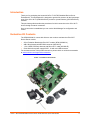
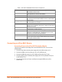
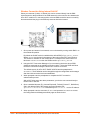
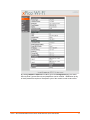
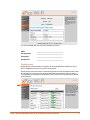
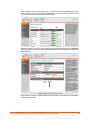
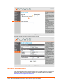
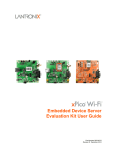
xPico™ Wi-Fi® Embedded Device Server Evaluation Kit Quick Start Guide Part Number 900-685 Revision A June 2013 Copyright and Trademark © 2013 Lantronix, Inc.. All rights reserved. No part of the contents of this book may be transmitted or reproduced in any form or by any means without the written permission of Lantronix. Lantronix® is a registered trademark of Lantronix, Inc. in the United States and other countries. xPico™ is a trademark of Lantronix, Inc. Windows® and Internet Explorer® are registered trademarks of Microsoft Corporation. Wi-Fi® is a registered trademark of the Wi-Fi Alliance Corporation. Firefox® is a registered trademark of Mozilla Foundation. Chrome™ is a trademark of Google, Inc. Safari® is a registered trademark of Apple Inc. All other trademarks, servicemarks and trade names are the property of their respective owners. Contacts Lantronix, Inc. 167 Technology Drive Irvine, CA 92618, U.S.A. Toll Free: 800-526-8766 Phone: 949-453-3990 Fax: 949-453-3995 Technical Support Online: http://www.lantronix.com/support Sales Offices For a current list of our domestic and international sales offices go to the Lantronix web site at www.lantronix.com/about/contact. Disclaimer and Revisions This equipment has been tested and found to comply with the limits for a Class B digital device, pursuant to Part 15 of the FCC Rules. These limits are designed to provide reasonable protection against harmful interference in a residential installation. This equipment generates, uses, and can radiate radio frequency energy and, if not installed and used in accordance with the instructions, may cause harmful interference to radio communications. However, there is no guarantee that interference will not occur in a particular installation. If this equipment does cause harmful interference to radio or television reception, which can be determined by turning the equipment off and on, the user is encouraged to try to correct the interference by one of the following measures: Reorient or relocate the receiving antenna. Increase the separation between the equipment and receiver. Connect the equipment into an outlet on a circuit different from that to which the receiver is connected. Consult the dealer or an experienced radio/TV technician for help. This device complies with Part 15 of the FCC Rules. Operation is subject to the following two conditions: (1) This device may not cause harmful interference, and (2) this device must accept any interference received, including interference that may cause undesired operation. This device is intended only for OEM Integrators. Revision History Date Rev. Comments June 2013 A Initial document. xPico™ Wi-Fi® Embedded Device Server Evaluation Kit Quick Start Guide 2 Table of Contents Copyright and Trademark _________________________________________________ 2 Contacts _______________________________________________________________ 2 Disclaimer and Revisions _________________________________________________ 2 Revision History _________________________________________________________ 2 Introduction ____________________________________________________________ 4 Evaluation Kit Contents ___________________________________________________ 4 What You Need to Know __________________________________________________ 5 Hardware Address ___________________________________________________ 5 Evaluation Kit Layout _____________________________________________________ 5 Connecting an xPico Wi-Fi Device __________________________________________ 6 Connecting Power to the xPico Wi-Fi Evaluation Module______________________ 6 Wireless Connection Using Internal Soft AP _______________________________ 7 QuickConnect _______________________________________________________ 9 Reference Documentation ________________________________________________ 11 xPico™ Wi-Fi® Embedded Device Server Evaluation Kit Quick Start Guide 3 Introduction Thank you for purchasing the Lantronix® xPico™ Wi-Fi® Embedded Device Server Evaluation Kit. This Evaluation Kit is designed to provide full access to all the input/output ports of the xPico Wi-Fi (XPW1001000-01) and xPico (wired Ethernet) (XPC1001000-01) modules. This quick start guide describes the procedures for initial connection to the xPico Wi-Fi device through a network connection. Once a connection is established you can use the Web Manager for configuration and control. Evaluation Kit Contents The XPW100100K-01 comes with all that a user needs to evaluate the xPico Wi-Fi Device Server module. xPico Evaluation Board with xPico Wi-Fi module (XPW1001000-01) 2dBi, Whip Antenna with RP SMA connector (930-033-R) 1.5 to 2.5dBi, PCB Strip Antenna with 50mm U.FL cable (930-099-R) 5Vdc Wall-mount power supply AC/DC, 1A with mini-USB connector For the latest revision of this product document, please check our online documentation at www.lantronix.com/support/documentation. Figure 1: Evaluation Kit Contents xPico™ Wi-Fi® Embedded Device Server Evaluation Kit Quick Start Guide 4 What You Need to Know Hardware Address The unit hardware address (also known as MAC address) is also used as the unique Serial Number to uniquely identify the unit. This number is located on the product label in the format SN: YYYYYYXXXXXX-, where the YY represents the Lantronix OUI and XXs are unique numbers within that OUI namespace assigned to the product. Hardware Address: _____-_____-_____-_____-_____-_____ Evaluation Kit Layout xPico™ Wi-Fi® Embedded Device Server Evaluation Kit Quick Start Guide 5 Table 1: xPico Wi-Fi Embedded Device Server Components Component Description xPico Serial Number Also the module MAC Address. The last six digits are used in the default SSID for Soft AP mode. Used to connect either the SMA antenna cable or the alternative PCB strip antenna to the xPico Wi-Fi Module. If using External antenna attach at this point. Power switch, turns power on and off to the Evaluation PCB. Mini-USB socket used for connecting power to the Evaluation Kit or to connect to the xPico module serial port 2 via an on-board USB to serial converter Battery Port (2.2 to 5.5V) provides power to the xPico Wi-Fi Module via on board DC to DC converter. DB9 for Serial Port 1 Leave JP11 and JP12 open for RS232 mode on serial port 1. Install jumper on JP11 for RS422 (4-wire) mode. Install JP11 and JP12 for RS485 (2 wire mode) Serial Port 1 break-out header. Leave jumpers installed to route module signals to J3 DB9 serial port Serial Port 2 RS232 header. Pin 1 TX(out), pin 2 GND, pin 3 RX(in) Jumpers for serial port 2 selection, install positions 1 to 2 to route serial port 2 to JP18 RS232 port. Install positions 2 to 3 to route serial port 2 to J5 USB to serial converter port. USB device port (xPico Wi-Fi only) RJ45 Ethernet Socket. This is not used with the xPico Wi-Fi module, it can be used if a xPico serial to Ethernet Device Server module is used in place of the xPico Wi-Fi Voltage test pins. Monitor only. JP14 is 3.3V and JP15 is Ground u.FL Socket SMA SW3 J5 JP19 (pin 1 +, pin 2 GND) J3 JP11 and JP12 JP17 JP18 JP8 and JP9 J6 J2 JP14, JP15 Connecting an xPico Wi-Fi Device Connecting Power to the xPico Wi-Fi Evaluation Module There are five methods of providing power to the Evaluation Kit PCB. Use one of the methods below. 1. Connect the provided universal power supply with mini-USB connector to J5. 2. Connect the USB to serial converter port J5 to a PC USB host port 3. Connect the USB device port J6 to a PC USB Host Port (xPico Wi-Fi only) 4. Connect a battery pack or external power supply (2.2V to 5.5V) between JP19 pin 1 (+) and JP19 pin 2 (-) 5. Connect Ethernet Port to a Power over Ethernet complaint PSE source (xPico module only) xPico™ Wi-Fi® Embedded Device Server Evaluation Kit Quick Start Guide 6 Wireless Connection Using Internal Soft AP Select your antenna of choice. If ducktail, this can be screwed directly into the SMA socket located on the Eval Board. If the PCB antenna is to be used, the wire between the xPico Wi-Fi module u.FL connector and the on-board SMA connector has to be carefully disconnected and the plug on the PCB strip antenna should be inserted. 1. Once power and antenna is connected, turn on the board by moving switch SW3 in to the marked ON position. By default the SoftAP mode is enabled with a default SSID of XpicoWiFi_xxxxxx. Where xxxxxx are the last six characters of the unique xPico Wi-Fi serial number. This number is available on the module label. For example if the serial number on label were 0080A398010E then the SSID would be XpicoWiFi_98010E. 2. Using the Wi-Fi Connection Manager of your connecting device the above SSID should be presented as an available connection choice. Select the SSID and follow the device connection manager instructions to continue to connect. The default security for xPico Wi-Fi SoftAP is WPA2 and the passphrase is XPICOWIFI. These defaults can be changed through the configuration web manager after the initial connection has been established. 3. When prompted enter the passphrase to complete the Wi-Fi connection authentication process. With a Wi-Fi client set to the above parameters, your device can connect directly to the xPico Wi-Fi Soft AP. 4. Open a standard browser (E.g. Internet Explorer®, Firefox®, Chrome™, Safari® etc.) and in the address field of the browser enter the following URL; xpicowifi.lantronix.com or alternatively use 192.168.0.1 as the IP Address. 5. When prompted enter the username of admin and password PASSWORD to access the Configuration and Management Web pages as shown below. xPico™ Wi-Fi® Embedded Device Server Evaluation Kit Quick Start Guide 7 By clicking Network > Network 1 > Link to get to the Configuration page, the SSID, Security Suite Type and Security and passphrase can be modified. Modification to any of these parameters requires a reset/power cycle of the module in order to take effect. xPico™ Wi-Fi® Embedded Device Server Evaluation Kit Quick Start Guide 8 It is recommended that you record any changes you make. SSID: ________________________________ Security Suite: ________________________________ Encryption: ________________________________ Passphrase: ________________________________ QuickConnect QuickConnect offers the ability to configure the STA (WLAN Client) interface on xPico WiFi to establish connection to an active Access Point. QuickConnect learns most of the connection properties from the available Access Points and prompts the user only for the security parameters and saves the settings under a corresponding new/existing WLAN profile for future autonomous operation of the WLAN Client interface. xPico™ Wi-Fi® Embedded Device Server Evaluation Kit Quick Start Guide 9 Upon selection of the QuickConnect option, the xPico Wi-Fi scans and displays up to 20 wireless devices in order of strongest signal strength at the top. Click on a network name to view the connection to that desired Access Point. When the selected Access Point profile displays, enter the password and click Submit to directly connect to the Access Point and to add the profile and configuration details to the WLAN profiles. Once added, the Quick Connect profile is connected and is accessible and configurable through WLAN Profiles. xPico™ Wi-Fi® Embedded Device Server Evaluation Kit Quick Start Guide 10 Click the new WLAN profile to view and modify settings. Reference Documentation For more information on the use and operation of the xPico Wi-Fi Device Server please refer to the latest product documents which are are available on the Product Website. www.lantronix.com/support/documentation. xPico™ Wi-Fi® Embedded Device Server Evaluation Kit Quick Start Guide 11