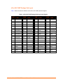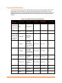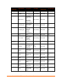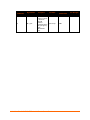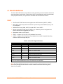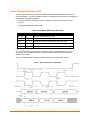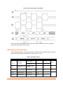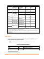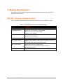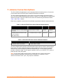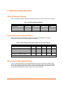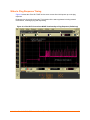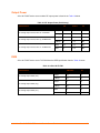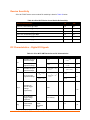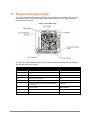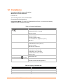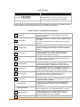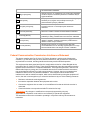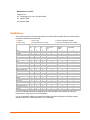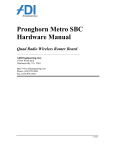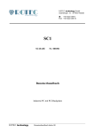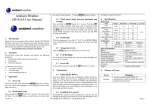
1
xPico® Wi-Fi SMT® Embedded Device Server Datasheet Models XPCW1002 & XPCW1003 December 2014 Description Applications Ideally suited for IOT applications the Lantronix® xPico® Wi-Fi® embedded device servers are a family of extremely compact low power networking solution that enables IEEE 802.11 wireless LAN connectivity on virtually any solution with a SPI or serial interface. Lantronix’ industryproven device server application and full IP stack allows seamless remote access to device data simplifying design integration while providing robust connectivity. Suitable example applications for the xPico Wi-Fi device server include such IOT applications as: The xPico Wi-Fi device servers are members of the Lantronix xPico product family providing unmatched flexibility whether it is Wi-Fi or Ethernet when it comes to choosing the right network device for your application. This document describes the xPico Wi-Fi surface mount technology versions. The xPico family also includes a functionally equivalent version of the Wi-Fi device (XPW1001000-01) that is provided in board to board connector that enables the interchangeability with the xPico embedded wired server (XPC1001000-01). As one of the smallest embedded device server in the world, xPico Wi-Fi device server can be utilized in designs typically intended for chip solutions, benefitting in advantages to cost and time to market. xPico Wi-Fi device servers are state-of-the-art and innovative solutions, that set new standards in reliability and functionality and offers all the capabilities one can expect including a unique simultaneous Soft-AP and Client mode. A key benefit with xPico Wi-Fi device server is that there is virtually no need to write a single line of code, translating to a much lower development cost and faster time-to-market Industrial o valve and sensor control, o Lock and access systems, Energy Management o Smart Meter Connectivity Medical o Connecting Infusion pumps to hospital IT Home Automation o water softening devices networking o Controlling home appliances from mobile devices Features Serial to Wi-Fi device server module with 802.11 b/g/n at 2.4GHz ARM Cortex M3 processor xPico SMT-76 castellation Form Factor o With on-board Antenna (est. 31.1mm x 18.3mm) o Without on-board Antenna (est. 26.1 mm x 18.31mm) Simultaneous SoftAP and client modes Supports Roaming, QuickConnect, Power Management Framework Low power of approximately 6µA standby Two serial ports (921Kbps) , SPI (30 MHz) , 1 and up to 8 GPIO USB. 2.0 Full Speed device port with integrated PHY. Feature-rich device server application suite, Full IP stack, and web server 256-bit AES Encryption, WPA2-Personal Industrial operating temperature of -40° to +85° C 5-Year Warranty xPico Wi-Fi device server are module approved, FCC Class B, UL and EN EMC and safety compliant. 1 Some interfaces share module pins. 910-816a xPico® Wi-Fi® SMT Embedded Device Server Datasheet 1 Table of Contents Description ________________________________________________________________ Applications _______________________________________________________________ Features __________________________________________________________________ List of Figures _____________________________________________________________ List of Tables ______________________________________________________________ 1 1 1 4 4 1: Introduction 6 2: Hardware and Software Description 7 3: Package Description and Mechanical Footprint 8 xPico W1002 and xPico W1003 Device Servers___________________________________ 8 Pin and Pad Definitions _____________________________________________________ 12 4: Host Interfaces UART ___________________________________________________________________ Serial Peripheral Interface (SPI) ______________________________________________ SPI Interface Characteristics _________________________________________________ USB Device ______________________________________________________________ Configurable General Purpose I/O Pins (GPIO) __________________________________ System Pins ______________________________________________________________ Reset Pins _______________________________________________________________ 15 15 16 17 18 19 19 20 5: Power, Reset, Wake, and Default Timing 21 6: Module Specifications 23 IEEE 802.11 Wireless LAN Specifications ______________________________________ 23 7: Antenna Connection Options 24 8: General Technical Data 25 9: Electrical Characteristics 26 Absolute Maximum Ratings __________________________________________________ Recommended Operating Conditions __________________________________________ Dynamic Power Management Modes __________________________________________ Wake to Ping Response Timing ______________________________________________ 910-816a xPico® Wi-Fi® SMT Embedded Device Server Datasheet 26 26 26 28 2 Output Power _____________________________________________________________ EVM ____________________________________________________________________ Receive Sensitivity ________________________________________________________ DC Characteristics – Digital I/O Signals ________________________________________ Flash Memory ____________________________________________________________ 10: Software Features Software Architecture Overview ______________________________________________ Soft AP Mode w/ DHCP Server _______________________________________________ Simultaneous Client and AP interfaces _________________________________________ WLAN Connection Management ______________________________________________ WLAN QuickConnect _______________________________________________________ WLAN Profiles ____________________________________________________________ Lantronix Serial to Wi-Fi Tunneling Application___________________________________ Transparent Tunneling Mode ________________________________________________ Modem Emulation Mode ____________________________________________________ AES Security _____________________________________________________________ Application Aware Power Management Framework _______________________________ Flexible Configuration Management Framework__________________________________ WEB Page Customization ___________________________________________________ SNTP Client ______________________________________________________________ Lantronix Application Toolbox for IOT solutions __________________________________ Serial Multiplexer __________________________________________________________ Over-The-Air Updates ______________________________________________________ Lantronix Query Port _______________________________________________________ 29 29 30 30 31 32 32 32 33 33 33 33 33 34 34 34 34 35 35 36 36 36 36 36 11: Product Information Label 38 12: Warranty 39 13: Evaluation Kit 40 Expansion Boards _________________________________________________________ 40 14: Compliance Federal Communication Commission Interference Statement ________________________ Radiation Exposure Statement _______________________________________________ Industry Canada Statement __________________________________________________ RoHS Notice _____________________________________________________________ 15: Ordering Information 41 43 44 44 47 48 Contact Information ________________________________________________________ 48 Preliminary Version History __________________________________________________ 49 910-816a xPico® Wi-Fi® SMT Embedded Device Server Datasheet 3 List of Figures Figure 1: xPico W1002 (XPC W1002) Embedded Device Server _________________________ 8 Figure 2: xPico W1003 (XPC W1003) Embedded Device Server _________________________ 8 Figure 3: Mechanical Footprint for xPico W1002 (without On-Module Antenna) Device Server __ 9 Figure 4: Layout Footprint for xPico W1002 (without On-Module Antenna) Device Server _____ 9 Figure 5: Mechanical Footprint for xPico W1003 (with On-Module Antenna) Device Server ___ 10 Figure 6: Layout Footprint for xPico W1003 (with On-Module Antenna) Device Server _______ 10 Figure 7: SPI Timing Diagram - Slave Mode ________________________________________ 16 Figure 8: SPI Timing Diagram – Master Mode ______________________________________ 17 Figure 9: Timing Requirements for VCC, Reset, Default and Wake ______________________ 21 Figure 10: xPico Wi-Fi Current from WAKE from Standby to Ping Response (Preliminary) ____ 28 Figure 11: xPico Wi-Fi Label ____________________________________________________ 38 List of Tables Table 1: xPico Wi-Fi SMT Package Pad Layout and Signals ___________________________ 11 Table 2: xPico Wi-Fi Interface Signal Definitions: ____________________________________ 12 Table 3: xPico UART Signal Definitions ____________________________________________ 15 Table 4: xPico W1001 UART Signal Definitions _____________________________________ 16 Table 5: SPI Characteristic _____________________________________________________ 17 Table 6: xPico USB Signal Definitions _____________________________________________ 18 Table 7: xPico GPIO Signal Definitions ____________________________________________ 19 Table 8: xPico System Signal Definitions __________________________________________ 19 Table 9: xPico Reset Signal Definitions ____________________________________________ 20 Table 10: Power Sequence Timing Requirements ___________________________________ 21 Table 11: xPico Wi-Fi Device Server Radio Specification ______________________________ 23 Table 12: xPico Wi-Fi SMT Device Server External Antenna Options ____________________ 24 Table 13: xPico Wi-Fi SMT Device Server On-Module Antenna _________________________ 24 Table 14: General Technical Data ________________________________________________ 25 Table 15: Absolute Maximum Ratings _____________________________________________ 26 Table 16: Recommended Operating Conditions for xPico Wi-Fi Module __________________ 26 Table 17: xPico Wi-Fi Power Management Modes (Preliminary Data Based upon Test Modes) 27 Table 18: RF Output Power (Preliminary) __________________________________________ 29 Table 19: xPico Wi-Fi EVM _____________________________________________________ 29 910-816a xPico® Wi-Fi® SMT Embedded Device Server Datasheet 4 Table 20: xPico Wi-Fi Device Server Module Rx Sensitivity ____________________________ 30 Table 21: xPico Wi-Fi SMT Device Server DC Characteristics __________________________ 30 Table 22: Country Certifications __________________________________________________ 41 Table 23: Country Transmitter IDs ________________________________________________ 41 Table 24: Safety ______________________________________________________________ 42 Table 25: Europe – EU Declaration of Conformity____________________________________ 42 Table 26: Approved Antenna(s) List ______________________________________________ 46 910-816a xPico® Wi-Fi® SMT Embedded Device Server Datasheet 5 1: Introduction This data sheet describes the SMT models; xPico W1002 and W1003 which are all referred to generally as xPico Wi-Fi SMT family of Embedded Wi-Fi device servers in this document The xPico W1002 and W1003 provide much of the circuitry and all of the software required to connect a micro controller or similar host device to an IEEE 802.11 b/g/n Wireless local area network (WLAN). The xPico W1000 family of device servers are available either in a very small and attractive 76-pad castellation surface mount package (SMT), or a connector version (xPico Wi-Fi device server, XPW1001000-01). The SMT form factor is itself available in two versions, with or without an onboard ceramic chip antenna. For the purposes of this document the xPico W1002 and xPico W1003 modules will be referred to collectively as xPico Wi-Fi SMT embedded device servers. For an embedded solution an external controller can connect through industry standard interfaces such as serial, SPI or USB 2.0 (Device) and with very little to no driver effort have the ability to connect and communicate to either an IEEE 802.11 b/g/n Access Point or Client. The xPico Wi-Fi SMT device server is targeted for applications that have a need to be Wi-Fi enabled with requirements of low power, single channel 802.11 b/g/n, industrial ready and ready to go solution at a very competitive price. The xPico Wi-Fi SMT device server is easy to integrate as Lantronix removes much of the design headaches by providing a platform with proven reliability with most of the necessary certification aspects taken care of and with very minimal software to develop. The xPico Wi-Fi SMT device server supports the unique mode of simultaneous Soft Access Point (Soft-AP) and Client. As a device server the device provides all the necessary functional programmability and protocols to maintain an efficient and robust WLAN connection. ♦ no additional code needed on MCU (Zero Host Load) ♦ MAC address included ♦ Little to no software integration needed The xPico Wi-Fi SMT device server benefits from the many years of experience Lantronix has with device servers, both wired and wireless. The xPico W1000 is easy to maintain. With technical support available and failsafe firmware upgrades from a remote manager. Key features of the xPico Wi-Fi SMT device server include: ♦ Lantronix Feature-rich device server application suite ♦ Wi-Fi Client ♦ Soft AP with DHCP server ♦ Lantronix QuickConnect, ♦ Industrial Temperature Operation (-40° to +85° C) ♦ Robust and reliable firmware upgradability ♦ Web server ♦ DHCP & DNS server in AP mode ♦ Serial Tunnel 910-816a xPico® Wi-Fi® SMT Embedded Device Server Datasheet 6 2: Hardware and Software Description The xPico Wi-Fi SMT embedded device server is a complete solution (hardware and software). This powerful device server comes with a connection manager, a reliable and proven operating system stored in flash memory, an embedded web server, a full TCP/IP protocol stack, and standards-based (AES) encryption. The xPico Wi-Fi SMT software runs on an ARM Cortex M3 controller and has an IEEE 802.11 b/g/n radio. The xPico Wi-Fi SMT device server communicates to the edge device through a serial, SPI or USB interface. The xPico Wi-Fi SMT device server runs on 3.3V, and has a built-in voltage supervisory circuit that will trigger a reset if the supply voltage drops to unreliable levels. 910-816a xPico® Wi-Fi® SMT Embedded Device Server Datasheet 7 3: Package Description and Mechanical Footprint The xPico Wi-Fi SMT device server is available in two package options. xPico W1002 and xPico W1003 Device Servers The xPico W1002 and XPCW1003 device servers are both surface mount modules that has the following dimensions and pad layout. The primary difference is the xPico W1003 module has an increase in size to accommodate the on-module antennal. Both devices have the same castellation and pad configuration and footprint. Figure 1: xPico W1002 (XPC W1002) Embedded Device Server Figure 2: xPico W1003 (XPC W1003) Embedded Device Server Dimensions The size and thickness of the xPico W1002 device server SMT module which is without the onmodule antenna is (estimated) 26.1 mm (L) x 18.3 mm (W) x 4.0mm (H) +/- 0.1 mm (including shielding). The PCB footprint is shown in Figure 4. 910-816a xPico® Wi-Fi® SMT Embedded Device Server Datasheet 8 Figure 3: Mechanical Footprint for xPico W1002 (without On-Module Antenna) Device Server Figure 4: Layout Footprint for xPico W1002 (without On-Module Antenna) Device Server 910-816a xPico® Wi-Fi® SMT Embedded Device Server Datasheet 9 The size and thickness of the xPico W1003 device server SMT module which is with the onmodule antenna is (estimated) 31.1 mm (L) x 18.3 mm (W) x 4.0mm (H) +/- 0.1 mm (including shielding). The footprint is shown in Figure 6 below. Figure 5: Mechanical Footprint for xPico W1003 (with On-Module Antenna) Device Server Figure 6: Layout Footprint for xPico W1003 (with On-Module Antenna) Device Server 910-816a xPico® Wi-Fi® SMT Embedded Device Server Datasheet 10 xPico Wi-Fi SMT Package Pad Layout Table 1 below contains the definition of the xPico Wi-Fi SMT pads and signals. Table 1: xPico Wi-Fi SMT Package Pad Layout and Signals PAD# xPico® WiFi SMT PAD# xPico® WiFi SMT PAD# xPico® WiFi SMT PAD# xPico® WiFi SMT 1 GND 2 RF1 3 GND 4 RESERVED 5 GND 6 RESERVED 7 RESERVED 8 RESERVED 9 RESERVED 10 RESERVED 11 RESERVED 12 CP3/MISO 13 CP4/MOSI 14 CP7/SCK 15 CP8/CS 16 CP5 17 CP6 18 USB1+ 19 USB1- 20 GND 21 RESERVED 22 RESERVED 23 GND 24 GND 25 RESERVED 26 RESERVED 27 GND 28 RESERVED 29 RESERVED 30 RESERVED 31 RESERVED 32 GND 33 RESERVED 34 RESERVED 35 GND 36 GND 37 RESERVED 38 RESERVED 39 WAKE 40 DEFAULT# 41 SYS_LED 42 CP2/INT 43 RESERVED 44 RESERVED 45 CP1 46 RESERVED 47 LED0/LNK 48 VCC 49 VCC 50 VCC 51 RESET# 52 RXD2 53 TXD2 54 CTS1 55 RTS1 56 RXD1 57 TXD1 58 GND 59 RF1_CTL 60 GND 61 GND 62 RESERVED 63 RESERVED 64 GND 65 GND 66 RESERVED 67 RESERVED 68 RESERVED 69 GND 70 GND 71 GND 72 GND 73 GND 74 GND 75 GND 76 GND 910-816a xPico® Wi-Fi® SMT Embedded Device Server Datasheet 11 Pin and Pad Definitions Table 2 describes the xPico Wi-Fi interface signal definitions as used in the SMT modules. The Signal Name column identifies the signal pin being described while the Description column provides definitions of the signal pin depending upon the member of the xPico family being used. Differentiating the signal pins is beneficial when using multiple xPico device types on a single platform. Table 2: xPico Wi-Fi Interface Signal Definitions: SMT Pad Number Signal Name Description 1, 3, 5, 20, 23, 24, 27, 32, 35, 36, 58, 60, 61, 64, 65, 69, 70, 71, 72, 73, 74, 75, 76 GND Signal Ground 2 RF1 RF antenna pad 4, 6, 7, 8, 9, 10, 11, 21, 22, 25, 26, 28, 31, 33, 34, 46, 30, 29, 43, 44, 62, 63, 66, 67, 68 RESERVED No Connect, Reserved for Future Use Internal Pullup/Pull Down Drive Strength CP3/MISO Configurable GPIO / SPI Master serial Input, Floating data input, SPI Slave serial data output 30K to 50K 8mA 13 CP4/MOSI Configurable GPIO / SPI Master serial Input, Floating data output, SPI Slave serial data input 30K to 50K 8mA 14 CP7/SPI_CLK Configurable GPIO / SPI clock Input, Floating 30K to 50K 8mA 15 CP8/SPI_CS Configurable I/O, multiplexed with SPI interface Chip Select Input, Floating 30K to 50K 8 mA 16 CP5 Configurable GPIO Input, Floating 30K to 50K 8mA 17 CP6 Configurable GPIO Input, Floating 30K to 50K 8mA 18 USB1+ USB (Positive) 12 Reset State 910-816a xPico® Wi-Fi® SMT Embedded Device Server Datasheet 12 SMT Pad Number Signal Name Description 19 USB1- USB (Negative) 39 WAKE System Wake Input, Floating Up or Shutdown 30K to 50K 40 DEFAULT# Unit reset to default, active low. Input, Floating Drive low to reset unit to default settings. 30K to 50K 41 SYSTEM_LED System Status LED, Active High Input, Floating 30K to 50K 8mA 42 CP2/SPI_INT Configurable GPIO / SPI interrupt External Interrupt input Input, Floating 30K to 50K 8mA 45 CP1 GPIO Input, Floating 30K to 50K 8mA 47 Wi-Fi LED LED function for WLAN Link Input, Floating indication, Active Low 30K to 50K 8 mA 48, 49, 50 VCC 3.3V Power Input 51 RESET# Unit hardware reset, active low. Input Drive low to Pull up reboot unit 30K to 50K 52 RXD2 UART2 serial receive data input Input, Floating 30K to 50K 53 TXD2 UART2 serial transmit data output Input, Floating 30K to 50K 54 CTS1 UART1 clear to send Input, Floating 30K to 50K 55 RTS1 UART1 serial ready to send (DTE) Input, Floating 30K to 50K 56 RXD1 UART1 Serial receive data input Input, Floating 30K to 50K 57 TXD1 UART1 serial transmit data output Input, Floating 30K to 50K Reset State 910-816a xPico® Wi-Fi® SMT Embedded Device Server Datasheet Internal Pullup/Pull Down Drive Strength 8mA 8mA 8mA 13 SMT Pad Number 59 Signal Name Description Reset State RF1_CTL Antenna Switch control. Pull low to select an external antenna Input Pull up connected to the RF1 pad (pin 2). Note XPCW1002 only. 910-816a xPico® Wi-Fi® SMT Embedded Device Server Datasheet Internal Pullup/Pull Down Drive Strength 100K 14 4: Host Interfaces The xPico Wi-Fi SMT device server offers a number of industry common interfaces to allow for easy connectivity to the module. These include UART for asynchronous serial communication, serial peripheral interface, for synchronous formatted data and USB host interface. UART ♦ The xPico Wi-Fi SMT device server supports two UART interfaces (UART1, UART2) ♦ Both UARTs support asynchronous data rate up to 921 Kbps, with Odd/Even parity, and 1 & 2 stop bits ♦ Software flow control (XON, XOFF) for both UART1 and UART2 ♦ Modem control (DTR, DCD) pins for UART1 only. Enabled by device configuration as pins are shared with configurable pins (CPs) ♦ Operational mode as a DTE device ♦ UART1 – supports TX, RX, RTS, CTS (hardware flow control) ♦ UART2 – supports TX, RX functions only. Hardware flow control is supported by using software controlled configurable pins. Table 3: xPico UART Signal Definitions Signal SMT Pin Description TXD1 57 Serial Port 1 Transmit Data output RXD1 56 Serial Port 1 Receive Data Input RTS1 55 Serial Port 1 Ready-to-Send/ Serial Transmit Enable CTS1 54 Serial Port 1 Clear to Send TXD2 53 Serial Port 2 Transmit Data output RXD2 52 Serial Port 2 Receive Data Input RTS2 * Serial Port 2 Ready-to-Send/ Serial Transmit Enable CTS2 * Serial Port 2 Clear to Send *. Note: Serial Port 2 Flow Control uses Configurable Pins, which can be shared with other functions. Refer to the xPico Wi-Fi Embedded Device Server User Guide for more information. Note: For xPico Wi-Fi 5V tolerant pins, in order to sustain a voltage higher than Vcc+0.3, the internal pull-up/pull-down resistors must be disabled. Refer to the xPico Integration Guide for more detail. 910-816a xPico® Wi-Fi® SMT Embedded Device Server Datasheet 15 Serial Peripheral Interface (SPI) The xPico Wi-Fi SMT device server has available a slave/master SPI interface that can be clocked at 30MHz. The SPI is multiplexed with five configurable GPIO pins and is managed by configuration at system initialization. ♦ Five Wire Interface consisting of Serial In, Serial Out, Chip Select, Serial Clock and Interrupt ♦ Configurable Master and Slave mode Table 4: xPico W1001 UART Signal Definitions Signal SMT Pin Description SPI_INT 42 SPI interrupt External Interrupt input SPI_CLK 14 SPI clock MISO 12 SPI Master serial data input, SPI Slave serial data output MOSI 13 SPI Master serial data output, SPI Slave serial data input SPI_CS 15 SPI Chip Select Note: For xPico Wi-Fi 5V tolerant pins, in order to sustain a voltage higher than Vcc+0.3, the internal pull-up/pull-down resistors must be disabled. Refer to the xPico Integration Guide for more detail. Figure 8 shows the relative timings on the SPI interface of the xPico Wi-Fi module. Figure 7: SPI Timing Diagram - Slave Mode 910-816a xPico® Wi-Fi® SMT Embedded Device Server Datasheet 16 Figure 8: SPI Timing Diagram – Master Mode See the xPico Wi-Fi Embedded Device Server User Guide for information on how to configure and use the SPI interface and its modes. SPI Interface Characteristics Unless otherwise specified, the parameters given in the table below for SPI are derived from tests performed under the ambient temperature of +25C, and VCC = 3.3V. Table 5: SPI Characteristic Symbol Parameter fSCK 1/tc(SCK) SPI clock frequency tr(SCL) tf(SCL) SPI clock rise and fall time Capacitive load: C=30pF DuCy(SCK) SPI slave input clock duty cycle Slave mode NSS setup time NSS Hold time tsu(NSS) th(NSS) (2) (2) Conditions Min Max Master mode - 30 Slave mode - 30 Unit MHz 8 Ns 30 70 % Slave mode 4tPCLK - Slave mode 2tPCLK - 910-816a xPico® Wi-Fi® SMT Embedded Device Server Datasheet Ns 17 Symbol (2) tw(SCLH) (2) tw(SCLL) (2) tSU(MI) (2) tSU(SI) (2) th(MI) (2) th(SI) ta(SO) (2) (3) tdls(SO) (2) (4) tv(SO) (2) (1) tv(MO) (2) (1) th(SO) (2) th(MO) (2) Parameter Conditions Min Max SCK high and low time Master mode, fPCLK=30 MHz, presc=2 tPCLK-3 tPCLK+3 Master mode 5 - Slave mode 5 - Master mode 5 - Slave mode 4 - Data output access time Slave mode, fPCLK=20 MHz, 0 3tPCLK Data output disable time Slave mode 2 10 Data output valid time Slave mode (after enable edge) - 25 Data output valid time Master mode (after enable edge) - 5 Slave mode (after enable edge) 15 - Master mode (after enable edge) 2 - Data input setup time Data input hold time Data output hold time Unit 1. Remapped SPI1 characteristics to be determined. 2. Based on characterization, not tested in production. 3. Min. time is for the minimum time to drive the output and the max time is for the maximum time to put data in Hi-Z. 4. Min time is for the minimum time to invalidate the output and the max time is for the maximum time to put the data in Hi-Z. USB Device The xPico Wi-Fi SMT device server has one certified USB 2.0 Full Speed (12MHz) Device port interface for connection to an upstream USB device. The port uses an integrated PHY and provides a differential pair, signals DDP and DDM. ♦ 2 Support for USB CDC/ACM Serial profile which will have the xPico Wi-Fi module appear as a CDC/ACM device enumerated as a virtual COM port. Table 6: xPico USB Signal Definitions 2 Signal SMT Pin Description USB1+ 18 USB1 Device Port Positive Pin USB1- 19 USB1 Device Port Negative Pin Available in a future software release. 910-816a xPico® Wi-Fi® SMT Embedded Device Server Datasheet 18 Configurable General Purpose I/O Pins (GPIO) The xPico Wi-Fi SMT device server provides up to eight configurable General Purpose Input/Output (GPIO) pins. Certain of the GPIOs are multiplexed with other interface functions (e.g. SPI). Mapping of these functions to CPs will be driven via configuration and applied at system initialization. Each CP can be configured as a general purpose input, general purpose output, microcontroller peripheral block or a soft function (e.g. modem control). These pins are 3.3V CMOS logic level and 5V input tolerant. For more information on how to use, configure and manage the utilization of the available GPIO please refer to the section on Configurable Pins in the xPico Wi-Fi Embedded Device Server User Guide. Note: For xPico Wi-Fi 5V tolerant pins, in order to sustain a voltage higher than Vcc+0.3, the internal pull-up/pull-down resistors must be disabled. Refer to the xPico Integration Guide for more detail. Table 7: xPico GPIO Signal Definitions Signal SMT Pin Description CP1 45 Configurable I/O CP2 42 Configurable I/O-SPI interrupt input CP3 12 Configurable I/O- SPI MISO CP4 13 Configurable I/O-SPI MOSI CP5 16 Configurable I/O CP6 17 Configurable I/O CP7 14 Configurable I/O-SPI Clock CP8 15 Configurable I/O-SPI Chip Select System Pins The following system pins are available in the product Table 8: xPico System Signal Definitions Signal SMT Pin Description WLAN LED 47 LED function for WLAN Link indication, Active Low. This signal is intended to drive an external LED. The blink patterns of the LED denote various WLAN states. SYSTEM_LED 41 System Status LED, Active High. This signal is intended to drive an external LED. The blink patterns of the LED denote various system states. 910-816a xPico® Wi-Fi® SMT Embedded Device Server Datasheet 19 Reset Pins xPico Wi-Fi device server has two signals that can be used as reset signals. Table 9: xPico Reset Signal Definitions SMT Pin Description DEFAULT# 40 Unit reset to default, active low. While device is running, drive low for greater than 6 seconds, then release to reset unit to factory defaults. While device is held in reset(EXT_RESET# low), drive low, release reset to boot device with Line 1 CLI default settings (original configuration is preserved), then release DEFAULT# after CLI session is established. EXT_RESET# 51 Unit hardware reset, active low. Assert low for a minimum of 50ms to reboot unit. Signal may be left floating. WKUP 39 Toggle signal from low to high can wake device from Sleep or Standby mode. Hold low to allow device to enter Sleep or Standby mode. Subject to configuration settings. Signal may be left floating. Signal Name 910-816a xPico® Wi-Fi® SMT Embedded Device Server Datasheet 20 5: Power, Reset, Wake, and Default Timing Figure 9: Timing Requirements for VCC, Reset, Default and Wake below shows the timing requirement for VCC, RESET#, DEFAULT#, and WAKE. Figure 9: Timing Requirements for VCC, Reset, Default and Wake Table 10 below lists the various power sequence timing requirements. Table 10: Power Sequence Timing Requirements Parameter Description Minimum Tpu Time for VCC to reach 90% of its maximum value 20 us/V Tpor Time from VCC to reach 90% of its maximum value and de-assertion of external reset. Note RESET# can be left floating if unused 0 S Treboot Recommended reset pulse for system reboot 300 ns 910-816a xPico® Wi-Fi® SMT Embedded Device Server Datasheet Maximum Unit 21 Parameter Description Minimum Tpup2dflt Time from VCC power up to DEFAULT# assertion. Note DEFAULT# can be left floating if unused. 0 ns Tdefault Assertion time for DEFAULT# to unit reset to default and reboot 6 S Twake Wake pulse width. Note wakeup is triggered on the rising edge. Note, WAKE signal may be left floating if unused. 1 us Twakeup Time from rising edge of WAKE signal to system up 910-816a xPico® Wi-Fi® SMT Embedded Device Server Datasheet Maximum Unit TBD 22 6: Module Specifications The following sections provide the specification and performance attributes of the xPico Wi-Fi SMT device server module. IEEE 802.11 Wireless LAN Specifications Table 11 shows the specifications for the xPico Wi-Fi SMT device server IEEE 802.11 radio. Table 11: xPico Wi-Fi Device Server Radio Specification Feature Description Frequency Band 2.412 – 2.484 GHz (Channels 1 – 14) Supported Data Rates 802.11n: 6.5, 13, 19.5, 26, 39, 52, 58.5, 65 Mbps 802.11g: 6, 9, 12, 18, 24, 36, 48, 54 Mbps 802.11b: 1, 2, 5.5, 11 Mbps Modulation OFDM with BPSK, QPSK, 16-QAM, 64-QAM 801.11b with CCK and DSSS Preamble Modes Long, Short, HT (800 ns) modes 802.11 MAC Features A-MPDU (Tx/Rx), WMM-PS, PSMP, Multiphase PSMP, Block Ack policy, RIFS AES (CCMP), TKIP, WEP 64/128-bit, WPA, WPA2 802.11 PHY Features 802.11b, 802.11g, 802.11n (Single-Stream) STBC Reception for extended range and higher throughput Greenfield mode (Tx/Rx) 802.11 modes b/d/g/h/i/j/k/n/w/r 910-816a xPico® Wi-Fi® SMT Embedded Device Server Datasheet 23 7: Antenna Connection Options The xPico W1002 embedded device server supports wireless connectivity via the u.fl connector on the module and one RF SMT pad for external PCB antenna connection. The xPico W1003 embedded device server offers an on-module ceramic chip antenna option only. The xPico W1003 module does not have the u.fl option or RF SMT pad for an external PCB antenna connection. xPico Wi-Fi SMT device servers are certified using the antennas listed in Table 12 and Table 13 below. Refer to the compliance section below for certification requirements related to antenna selection. Table 12: xPico Wi-Fi SMT Device Server External Antenna Options Antenna Type Peak Gain Typical Vendor Vendor Part Number Swivel type antenna, with RP-SMA(M) connector 2 dBi, 2.4 GHz to 2.5 GHz Wanshih WSS002 PCB Strip Antenna with 50mm cable to U.FL connector With tape backing 1.5-2.5 dBi 2.4 GHz to 2.5 GHz Ethertronics 1001077 Table 13: xPico Wi-Fi SMT Device Server On-Module Antenna Antenna Type Peak Gain Typical On module ceramic chip antenna 2.5 dBi 2.4Ghz to 2.5Ghz The xPico W1002 module provides an RF Pad/external trace option to solder a custom antenna to the device. The xPico Integration Guide provides guidelines on how to connect an external antenna to the device through a RF PCB trace transmission line. The integration guide also provides a reference design. The RF signal is available on RF1, pin 2, when RF_CTL, pin 59, is pulled low with a low ohm resistor. Note: The xPico Wi-Fi SMT module has been certified with the on module chip antenna and the antennas listed above connected to the on module U.FL connector. Use of antenna connections to RF1, pin 2, may require re-certification. 910-816a xPico® Wi-Fi® SMT Embedded Device Server Datasheet 24 8: General Technical Data Table 14: General Technical Data Category Description Firmware OTA Upgradable Internal Web Server Serves Web Pages Storage Capacity: 512 KB Weight 2.6 grams (xPico W1002 embedded device server) 2.75 grams (xPico W1003 embedded device server) Material Metal Shell Temperature Operating Range: -40°C to +85°C (-40°F to +185°F) Storage Range: 40°C to +85°C (-40°F to +185°F) Relative Humidity Operating: 5% to 85% no- condensing Shock/Vibration Non-operational Shock: 500 g’s. Non-operational vibration: 20 g’s. 910-816a xPico® Wi-Fi® SMT Embedded Device Server Datasheet 25 9: Electrical Characteristics Absolute Maximum Ratings Table 15 shows the maximum rating as specified for the xPico Wi-Fi SMT device server module. Table 15: Absolute Maximum Ratings Parameter Symbol Min Max Units Supply Power VCC -0.3 3.6 V DC Operating Temperature - 40 85 Storage Temperature - 40 85 ⁰C ⁰C Recommended Operating Conditions Table 16 specifies the recommended operation conditions and Parameters for optimum performance of the xPico Wi-Fi SMT device server module. Table 16: Recommended Operating Conditions for xPico Wi-Fi Module Parameter Symbol Min Typ Max Units Voltage VCC 3.0 3.3 3.6 V DC Supply Voltage Ripple VCC pp Operating Temperature Extended Operating Temperature ** ± 2% Ta -20 +70 Ta -40 +85 ⁰C 85 % Humidity (non-condensing, relative) ⁰C ** Dynamic Power Management Modes Table 17 below describes the four Power Management modes for the xPIco Wi-Fi SMT device server, along with their typical and maximum current consumption values. The xPico Wi-Fi SMT device server supports three modes within its Dynamic Power Management Framework. Powerup, Sleep and Standby Modes. Refer to page 34 for further information. 910-816a xPico® Wi-Fi® SMT Embedded Device Server Datasheet 26 Table 17: xPico Wi-Fi Power Management Modes (Preliminary Data Based upon Test Modes) Parameter Symbol Min AP mode enabled, WLAN0 connected to AP with ping. (Average current). ICC 90 mA AP mode enabled WLAN0 disabled. (Average current) ICC 90 mA Transmit surge current @ 16.5dBm, 802.11b, 11Mbps ICC 330 380 mA Transmit surge current @ 15dBm, 802.11g, 6Mbps ICC 300 345 mA Transmit surge current @ 13dBm, 802.11g, 54Mbps ICC 255 295 mA Transmit surge current @ 14.5dBm, 802.11n, MCS0 ICC 290 335 mA Transmit surge current @ 12dBm, 802.11n, MCS7 ICC 230 265 mA AP mode enabled, WLAN0 connected to AP with 921Kbaud bi-directional serial traffic. (Average current) ICC 139 mA WLAN0 power management enabled and connected to AP with no traffic , AP mode disabled (Average current) ICC 36 mA WLAN0 power management enabled and connected to AP with bi-directional tunnel stream , AP mode disabled (Average current) ICC 76 mA CPU Idle, RAM Contents Valid, Peripherals On, STA mode – connected to AP (PS-POLL active). (Average current) ICC 13.5 mA Sleep Mode; CPU Sleep, RAM Contents Valid, Most peripherals ON, Radio – Deep Sleep (disconnected from AP). (Average current) ICC 3 mA Standby Mode @ +25°C (Average current) Standby Mode – CPU Off, Radio Deep Sleep no association to AP, RTC Wake only. (Average current) ICC 6 uA Standby Mode @ +85°C Standby Mode – CPU Off, Radio Deep Sleep no association to AP, RTC Wake only. (Average current) ICC 12 μA Standby Mode @ -40°C Standby Mode – CPU Off, Radio Deep Sleep no association to AP, RTC Wake only. (Average current) ICC 5 μA 910-816a xPico® Wi-Fi® SMT Embedded Device Server Datasheet Typical Max Units 27 Wake to Ping Response Timing Figure 10 shows the xPico Wi-Fi SMT device server current from initial power up to unit ping response. Response time is typically 4 seconds. This includes all the start-up phases including network reconnection, receiving a ping and responding. Figure 10: xPico Wi-Fi Current from WAKE from Standby to Ping Response (Preliminary) 910-816a xPico® Wi-Fi® SMT Embedded Device Server Datasheet 28 Output Power xPico Wi-Fi SMT device server module RF output power is listed in the Table 18 below Table 18: RF Output Power (Preliminary) Characteristics RF Average Output Power, 802.11b CCK Mode RF Average Output Power, 802.11g OFDM Mode RF Average Output Power, 802.11n OFDM Mode TYP. Criteria Unit 1 Mbps 16.5 ± 1.5 dBm 11 Mbps 16.5 ±1.5 dBm 6 Mbps 15 ± 1.5 dBm 54 Mbps 13 ± 1.5 dBm MCS0 14.5 ± 1.5 dBm MCS7 12 ± 1.5 dBm EVM xPico Wi-Fi SMT device server TX EVM follow the IEEE specification listed in Table 19 below Table 19: xPico Wi-Fi EVM Characteristics RF Average Output EVM (11b) RF Average Output EVM (11g) RF Average Output EVM (11n) EVM Value Unit 1 Mbps -10 dB 11 Mbps -10 dB 6 Mbps -5 dB 54 Mbps -25 dB MCS0 -5 dB MCS7 -28 dB 910-816a xPico® Wi-Fi® SMT Embedded Device Server Datasheet 29 Receive Sensitivity xPico Wi-Fi SMT device server module Rx sensitivity is listed in Table 20 below. Table 20: xPico Wi-Fi Device Server Module Rx Sensitivity Receiver Characteristics TYP. MAX. PER <8%, Rx Sensitivity @ 1 Mbps -93 -89 PER <8%, Rx Sensitivity @ 11 Mbps -88 -84 PER <10%, Rx Sensitivity @ 6 Mbps -87 -83 PER <10%, Rx Sensitivity @ 54 Mbps -74 -70 PER <10%, Rx Sensitivity @ MCS0 -87 -83 PER <10%, Rx Sensitivity @ MCS7 -71 -67 DC Characteristics – Digital I/O Signals Table 21: xPico Wi-Fi SMT Device Server DC Characteristics Symbol VIL VIH Parameter Ilkg Min Standard IO input low level voltage -0.3 IO FT (1) input high level voltage -0.3 Standard IO input low level voltage IO FT (1) input high level voltage Vhys Conditions (𝑉𝑉𝐷𝐷𝐷𝐷 > 2 ) (𝑉𝑉𝐷𝐷𝐷𝐷 ≤ 2 ) 0.41 (𝑉𝑉𝐷𝐷𝐷𝐷 − 2) + 1.3 0.42 (𝑉𝑉𝐷𝐷𝐷𝐷 − 2) + 1.0 Standard IO Schmitt trigger voltage hysteresis(2) 200 IO FT Schmitt trigger voltage hysteresis 5% VDD (3) Input leakage current (4) Typ Max 0.28 (𝑉𝑉𝐷𝐷𝐷𝐷 − 2) + 0.8 0.32 (𝑉𝑉𝐷𝐷𝐷𝐷 − 2) + 0.75 (𝑉𝑉𝐷𝐷𝐷𝐷 + 0.3 ) Unit V V V 5.5 V 5.2 mV VSS ≤ VIN ≤ VDD Standard I/Os 910-816a xPico® Wi-Fi® SMT Embedded Device Server Datasheet ±1 µA 30 Symbol Parameter Conditions Min Typ VIN=5 V, I/O FT Max Unit 3 RPU Weak pull-up equivalent resistor (5) VIN=VSS 30 40 50 kΩ RPD Weak pull-down equivalent resistor (5) VIN=VDD 30 40 50 kΩ CIO I/O pin capacitance 5 pF FT = Five-volt tolerant. In order to sustain a voltage higher than VDD+0.3 the internal pullup/ pull-down resistors must be disabled. Hysteresis voltage between Schmitt trigger switching levels. Based on characterization, not tested in production. With a minimum of 100 mV. Leakage could be higher than max. if negative current is injected on adjacent pins. Pull-up and pull-down resistors are designed with a true resistance in series with a switchable PMOS/NMOS. This MOS/NMOS contribution to the series resistance is minimum (~10% order). Flash Memory The xPico Wi-Fi SMT device server comes with the following memory profile: MCU Embedded Flash Memory The MCU embeds a 1Mbyte Flash memory. It is used to store the boot loader, production configuration data and program/firmware. The firmware and production configuration data are programmed via the Firmware Upgrade application. Additional SPI Flash There is a separate on-module 1MByte SPI flash to extend the storage capacity. It is used as a file system store for customer files for serving via HTTP, logging files and for storing the firmware upgrade/recovery application. The features of the SPI Flash are as follows: ♦ 100,000 erase/program cycles (typical) ♦ 20 years data retention 910-816a xPico® Wi-Fi® SMT Embedded Device Server Datasheet 31 10: Software Features Software Architecture Overview The following represents the functional block diagram and architecture of the xPico Wi-Fi Family of embedded device servers. The following features are provided with the xPico Wi-Fi SMT device server software. Soft AP Mode w/ DHCP Server The xPico Wi-Fi SMT device server has the ability of allowing up to four Wi-Fi clients to connect to a Soft Access Point in a simple and standard manner. The SoftAP also includes a DNS to allow access to pages served by the on device web server. 910-816a xPico® Wi-Fi® SMT Embedded Device Server Datasheet 32 Simultaneous Client and AP interfaces The xPico Wi-Fi SMT device server has the ability to operate as Wi-Fi Client and provide a Soft Access Point mode both at the same time. This allows the device to communicate to a network access point, while simultaneously allow up to four other clients to connect to it. Service personnel do not need to determine the credentials of the network in which their product is deployed in order to wireless gain access to the service interface on the product. Device communication is maintained across both the AP and client interface without interruption. WLAN Connection Management Managing connectivity to wireless networks, retrying on lost connections, ensuring IP level connectivity is maintained, working across re-configurations are all tasks that the WLAN Connection Manager handles out of the box. Combined with other features such as WLAN QuickConnect and WLAN Profiles, a robust and full featured WLAN connection manager reduces connection downtime, enables quicker deployment and eliminates the complicated state management that has to be implemented on connected microcontrollers/devices to support such functionality. WLAN QuickConnect WLAN QuickConnect allows users to add setup/provision the wireless network configuration for the WLAN client interface quickly by presenting an intuitive workflow and user interface that is familiar to Smartphone users. It also simplifies the process of connecting to legacy wireless networks that use WEP security via the EasyWEP capabilities built into QuickConnect and the WLAN Connection Manager. WLAN Profiles In many scenarios, it is essential to store and connect automatically to one of multiple wireless networks available. WLAN Profiles makes it easy to configure and store the settings associated with these multiple networks. Together with WLAN QuickConnect and the bulk configuration via XML, it makes the provisioning process very straightforward. Lantronix Serial to Wi-Fi Tunneling Application Lantronix offers multiple modes for connected device data acquisition and control. Depending on the nature of the application running on the connected microcontroller, these modes offer a flexible and robust out-of-the-box solution that has been deployed across millions of units xPico Wi-Fi SMT device server also support the ability to enable AES encryption of the users TCP data for both Accept and Connect Tunnel Modes. 910-816a xPico® Wi-Fi® SMT Embedded Device Server Datasheet 33 Transparent Tunneling Mode Legacy applications running on microcontrollers that cannot be modified or where the requirements for data communication are simple, Transparent Tunnel mode provide a rich set of configuration options and knobs to manage the connection management, data framing and transfer process to suit many application protocol requirements. The various features of transparent tunnel mode are: ♦ Accept Mode (Server mode for incoming connections) ♦ Connect Mode (Client mode for outbound connections) ♦ Triggered Connect Modes ♦ Hostlist Mode* (Multiple virtual serial session connectivitiy) ♦ Disconnect Mode (Session teardown options) ♦ Data Framing/Packetizing Options ♦ Session Establishment and Teardown trigger actions ♦ Choice of TCP, UDP*, TCP-AES, UDP-AES* encapsulation protocol Modem Emulation Mode Modem Emulation Mode supports the more traditional AT-command driven interface for microcontrollers that can support interactive connection control and would like to switch between control interface and data interface on demand. It increases the overall state management complexity on the connected microcontroller compared to Transparent Tunnel mode, but can be helpful where knowledge and usage of AT commands (even though more complicated) is absolutely necessary AES Security The xPico Wi-Fi embedded device server supports the use of 256-bit AES encryption in order to provide security protection of the User Data. Tunneling Security for TCP AES is enabled for both Accept and Connect Tunnel configurations. Application Aware Power Management Framework The xPico Wi-Fi SMT device server is intended to be used in products that require or are sensitive to the amount of power they consume, for example battery powered applications. Consequently the power management framework for the xPico Wi-Fi embedded device server is intended to provide a framework that users can manage their device power consumption dependent upon their needs and requirements. The framework offers application aware power modes that allow the user to choose the method that meets their needs for a compromise between power consumption and the time to respond, wake up and reacquire connectivity. It is generally accepted that the lowest power consuming mode results in a longer response time from the power saving state to being fully active and connected. The power management framework includes the ability to be managed by using a dedicated Wake-Up System Pin. 910-816a xPico® Wi-Fi® SMT Embedded Device Server Datasheet 34 The Power Management Framework consists of three modes of operation. 1. Power Up Mode 2. Sleep Mode 3. Standby Mode Power Up Mode This is the only mode available if the Access Point is enabled or if none of the other Power Saving modes are enabled for the WLAN interface. Even in the Fully Active mode, the xPico embedded device server provides some form of power savings capability. The xPico Wi-Fi module supports “ps-poll” capability where a STA makes an initial association with an access point, it negotiates and informs of its ability of going into a low power mode and what that low power duration is. The Access Point must be capable of supporting the standard capabilities of Traffic Indication Map (TIM) and Power Save Poll (ps-poll). The xPico Wi-Fi module automatically manages this capability in the Fully Active Mode. Sleep Mode Sleep mode causes the xPico Wi-Fi to power down the Wi-Fi radio and system clocks while preserving the system state. This mode offers a compromise of power versus wake response time for those applications that need reduced power consumption with a speedy wake up and connection reacquisition response time. Standby Mode Standby mode of operation provides the lowest power consumption. In this mode the xPico Wi-Fi has the only the RTC operating and the system runtime state is not preserved. This mode has the longest wake up response time, since the system state has to be reinitialized and connections reacquired. Flexible Configuration Management Framework The xPico Wi-Fi SMT device server provides a unified framework in how the device can be controlled, configured and managed. For full details refer to the xPico Wi-Fi Embedded Device Server User Guide. • • • • • XML Import and Export Save/Restore configuration on Flash Reset to Defaults – Command and Hardware Pin OEM Configuration Management TLOG Display and Syslog Redirection WEB Page Customization The xPico Wi-Fi embedded device server includes an embedded Web Server. This Web Server provides the user a browser based configuration tool. The unit’s configuration is stored in nonvolatile memory and is retained without power. The Web Server has the ability to support the use of a custom landing page, which can take precedence over the default home page. The pages can be modified to suit a customer’s need in regard changing Logos, Background and Color Scheme, visible menus and options. Custom pages are supported with data being capable of being sent or received to a connected host device. 910-816a xPico® Wi-Fi® SMT Embedded Device Server Datasheet 35 SNTP Client The xPico Wi-Fi SMT device server provides support for Simple Network Timing Protocol. This easy to configure integrated Client allows the user to be always be synchronized to Internet time. Time can be synchronized either by using XML on the serial port or by using WebAPI. Lantronix Application Toolbox for IOT solutions Lantronix Application Toolbox for IOT solutions (LATIS) is an architecture that uses application tools to support a easy to use “Customization by configuration” Paradigm. An on device Application Server facilitates the simple interfacing of network interfaces/Web server to Host processor/Client with a common database/cache. LATIS enables the user to create application specific customization of the end user product without the need to use an SDK or write software. Custom user Data from a Web Page can be stored and used via the on device FLASH File system. Changes to data can initiate an interrupt that notifies a connected device to fetch the updated data. Serial Multiplexer As an interface serial ports tend to be used as a dedicated data channel between two points. With data generally being asynchronous with a simple ‘character’ format that indicates the start and stop and sometimes error checking. With the xPIco Wi-Fi embedded device server there is a need to establish multiple data channels in order to support multiple applications simultaneously. This requires the need to create a protocol that supports the differentiation of data. The xPico Wi-Fi embedded device server provides a “Mux” Line Protocol for the serial Line to manage and transfer data on multiple connections without requiring custom software on the device. A host processor that is connected to the device via the serial Line sees a simple command/response interface. There are no intentional delays required in the normal handshake. Over-The-Air Updates xPico Wi-Fi SMT device server provides a robust and secure method for the updating of device firmware over the internet. This update process uses the existing WLAN configuration and preserves the user configuration and profiles. Using the embedded web interface makes the update process simple and is user friendly. For a more scripted and automated method the same updates can be done via the WebAPI. Lantronix Query Port The xPico Wi-Fi embedded device server support the Lantronix query Port discovery service. Query Port is a Lantronix proprietary protocol. Which implements a simple protocol on port 910-816a xPico® Wi-Fi® SMT Embedded Device Server Datasheet 36 0x7FFE (30718). This service can be used by the Lantronix network tools such as Device Installer or ComPort Redirector. 910-816a xPico® Wi-Fi® SMT Embedded Device Server Datasheet 37 11: Product Information Label The product information label contains important information about your specific unit, such as its part number, revision, manufacturing date code, product model, country of origin, datamatrix barcode and MAC address. Figure 11: xPico Wi-Fi Label The xPico Wi-FI SMT embedded device server uses the Datamatrix ECC200 barcode standard. The field definitions are as follows Field Description Example V1 Barcode format revision 1 C1 Field count. 6 P1 Part number of the module XPCW1003100 R1 Revision of the module A11 D1 Manufacturing Datecode of the module 14W20 L1 Country and Factory ID# of who manufactured the module CHINA 03 S1 Serial number 0080A3980404 M1 MAC address 0080A3980404 E1 End of Barcode 910-816a xPico® Wi-Fi® SMT Embedded Device Server Datasheet 38 12: Warranty The xPico Wi-Fi SMT device server comes with an industry best 5-year Warranty. For more details on the Lantronix warranty replacement policy, please go to our web site at www.lantronix.com/support/warranty. 910-816a xPico® Wi-Fi® SMT Embedded Device Server Datasheet 39 13: Evaluation Kit An xPico Wi-Fi device server evaluation kit is available to provide a simple, quick and cost effective way to evaluate the xPico Wi-Fi device server. Use the Evaluation kit to integrate the device into to your product design and find out how simple, easy it is to get started. In order to evaluate the xPico Wi-Fi SMT embedded device server Lantronix provides two evaluation kits. The XPCW1003100K, is a single board with the xPico Wi-Fi W1003 module mounted. This allows the simple use of the device and using the on module antenna version. The Board includes the necessary keep out areas, so performance and positioning can be evaluated. The second option is the XPCW1002100K, which is a bundle of an evaluation board plus the xPico Wi-Fi W1002 module on a carrier board. This system mounts the carrier board onto a 40pin Hirose connector (same as used for the xPIco Wi-Fi B2B connector version). Expansion Boards The xPico Wi-Fi XPW1001 embedded device server is also available as an expansion board for several popular microprocessor development and prototype platforms. Please see the list below for general information or refer to the xPico Wi-Fi product web pages at http://www.lantronix.com/device-networking/embedded-device-servers/xpico-wifi.html 910-816a xPico® Wi-Fi® SMT Embedded Device Server Datasheet 40 14: Compliance (According to ISO/IEC Guide and EN 45014) Manufacturer's Name & Address: Lantronix, Inc. 167 Technology Drive, Irvine, CA 92618 USA Declares that the following product: Product Name Model: xPico® Wi-Fi® Embedded Device Server Conforms to the following standards or other normative documents: Table 22: Country Certifications Country Specification FCC Part 15, Subpart B, Class B USA ICES-003:2012 Issue 5, Class B ANSI C63.4-2009 USA FCC Part 15, Subpart C (Section 15.247) ANSI C63.10-2009 FCC Part 2 (Section 2.1091) FCC OET Bulletin 65, Supplement C (01-01) IEEE C95.1 Canada Canada RSS-210 Issue 8 (2010-12) Canada RSS-Gen Issue 3 (2010-12) ANSI C63.10-2009 RSS-102 Issue 4 (2010-12) EU EN 300 328 V1.8.1 (2012-06) EN 301 489-1 V1.9.2 (2011-09) EN 301 489-17 V2.2.1 (2012-09) EN 55022:2010+AC:2011, Class B EN62311:2008 AS/NZS 4268: 2012 Australia, New Zealand Japan N11206 ARIB STD-T66, MIC notice 88 Appendix 43 RCR STD-33, MIC notice 88 Appendix 44 Table 23: Country Transmitter IDs Country Specification USA FCC ID R68XPICOW Canada IC ID 3867A-XPICOW Japan ID 201-135275 910-816a xPico® Wi-Fi® SMT Embedded Device Server Datasheet 41 Table 24: Safety Country World Wide Specification CB EN 60950-1:2006 + A11:2009 + A1:2010 + A12:2011 In accordance with the council directive 2006/95/EC US, Canada UL 60950-1 (2nd Edition) Hereby, Lantronix, declares that this xPico Wi-Fi embedded device server is in compliance with the essential requirements and other relevant provisions of Directive 1999/5/EC. Table 25: Europe – EU Declaration of Conformity cs Česky [Czech] da Dansk [Danish] Lantronix, Inc. tímto prohlašuje, že tento xPico Wi-Fi je ve shodě se základními požadavky a dalšími příslušnými ustanoveními směrnice 1999/5/ES. Undertegnede Lantronix, Inc. erklærer herved, at følgende udstyr xPico Wi-Fi overholder de væsentlige krav og øvrige relevante krav i direktiv 1999/5/EF. de Deutsch [German] Hiermit erklärt Lantronix, Inc., dass sich das Gerät xPico Wi-Fi in Übereinstimmung mit den grundlegenden Anforderungen und den übrigen einschlägigen Bestimmungen der Richtlinie 1999/5/EG befindet. et Eesti [Estonian] Käesolevaga Lantronix, Inc. seadme xPico Wi-Fi vastavust direktiivi 1999/5/EÜ põhinõuetele ja nimetatud direktiivist tulenevatele teistele asjakohastele sätetele. en English Hereby, Lantronix, Inc., declares that this xPico Wi-Fi is in compliance with the essential requirements and other relevant provisions of Directive 1999/5/EC. es Español [Spanish] Por medio de la presente Lantronix, Inc. declara que el xPico Wi-Fi cumple con los requisitos esenciales y cualesquiera otras disposiciones aplicables o exigibles de la Directiva 1999/5/CE. el Ελληνική [Greek] ΜΕ ΤΗΝ ΠΑΡΟΥΣΑ Lantronix, Inc. ΔΗΛΩΝΕΙ ΟΤΙ xPico Wi-Fi ΣΥΜΜΟΡΦΩΝΕΤΑΙ ΠΡΟΣ ΤΙΣ ΟΥΣΙΩΔΕΙΣ ΑΠΑΙΤΗΣΕΙΣ ΚΑΙ ΤΙΣ ΛΟΙΠΕΣ ΣΧΕΤΙΚΕΣ ΔΙΑΤΑΞΕΙΣ ΤΗΣ ΟΔΗΓΙΑΣ 1999/5/ΕΚ. fr Français [French] Par la présente Lantronix, Inc. déclare que l'appareil xPico Wi-Fi est conforme aux exigences essentielles et aux autres dispositions pertinentes de la directive 1999/5/CE. it Italiano [Italian] Con la presente Lantronix, Inc. dichiara che questo xPico Wi-Fi è conforme ai requisiti essenziali ed alle altre disposizioni pertinenti stabilite dalla direttiva 1999/5/CE. Latviski [Latvian] Ar šo Lantronix, Inc. deklarē, ka xPico Wi-Fi atbilst Direktīvas 1999/5/EK būtiskajām prasībām un citiem ar to saistītajiem noteikumiem. Lietuvių [Lithuanian] Šiuo Lantronix, Inc. deklaruoja, kad šis xPico Wi-Fi atitinka esminius reikalavimus ir kitas 1999/5/EB Direktyvos nuostatas. Nederlands [Dutch] Hierbij verklaart Lantronix, Inc. dat het toestel xPico Wi-Fi in overeenstemming is met de essentiële eisen en de andere relevante bepalingen van richtlijn 1999/5/EG. nl mt Malti [Maltese] Hawnhekk, Lantronix, Inc.], jiddikjara li dan xPico Wi-Fi jikkonforma 910-816a xPico® Wi-Fi® SMT Embedded Device Server Datasheet 42 mal-ħtiġijiet essenzjali u ma provvedimenti oħrajn relevanti li hemm fid-Dirrettiva 1999/5/EC. hu Magyar [Hungarian] Alulírott, Lantronix, Inc. nyilatkozom, hogy a xPico Wi-Fi megfelel a vonatkozó alapvetõ követelményeknek és az 1999/5/EC irányelv egyéb elõírásainak. pl Niniejszym Lantronix, Inc. oświadcza, że xPico Wi-Fi jest zgodny z zasadniczymi wymogami oraz pozostałymi stosownymi postanowieniami Dyrektywy 1999/5/EC. Polski [Polish] pt Português [Portuguese] Lantronix, Inc. declara que este xPico Wi-Fi está conforme com os requisitos essenciais e outras disposições da Directiva 1999/5/CE. sl Slovensko [Slovenian] Lantronix, Inc. izjavlja, da je ta xPico Wi-Fi v skladu z bistvenimi zahtevami in ostalimi relevantnimi določili direktive 1999/5/ES. Slovensky [Slovak] Lantronix, Inc. týmto vyhlasuje, že xPico Wi-Fi spĺňa základné požiadavky a všetky príslušné ustanovenia Smernice 1999/5/ES. Suomi [Finnish] Lantronix, Inc. vakuuttaa täten että xPico Wi-Fi tyyppinen laite on direktiivin 1999/5/EY oleellisten vaatimusten ja sitä koskevien direktiivin muiden ehtojen mukainen. sv Svenska [Swedish] Härmed intygar Lantronix, Inc. att denna xPico Wi-Fi står I överensstämmelse med de väsentliga egenskapskrav och övriga relevanta bestämmelser som framgår av direktiv 1999/5/EG. fi Federal Communication Commission Interference Statement This device complies with Part 15 of the FCC Rules. Operation is subject to the following two conditions: (1) This device may not cause harmful interference, and (2) this device must accept any interference received, including interference that may cause undesired operation. This equipment has been tested and found to comply with the limits for a Class B digital device, pursuant to Part 15 of the FCC Rules. These limits are designed to provide reasonable protection against harmful interference in a residential installation. This equipment generates, uses and can radiate radio frequency energy and, if not installed and used in accordance with the instructions, may cause harmful interference to radio communications. However, there is no guarantee that interference will not occur in a particular installation. If this equipment does cause harmful interference to radio or television reception, which can be determined by turning the equipment off and on, the user is encouraged to try to correct the interference by one of the following measures: ♦ Reorient or relocate the receiving antenna. ♦ Increase the separation between the equipment and receiver. ♦ Connect the equipment into an outlet on a circuit different from that to which the receiver is connected. ♦ Consult the dealer or an experienced radio/TV technician for help. FCC Caution: Any changes or modifications not expressly approved by the party responsible for compliance could void the user's authority to operate this equipment. This transmitter must not be co-located or operating in conjunction with any other antenna or transmitter. 910-816a xPico® Wi-Fi® SMT Embedded Device Server Datasheet 43 Radiation Exposure Statement This equipment complies with FCC radiation exposure limits set forth for an uncontrolled environment. This equipment should be installed and operated with minimum distance 20cm between the radiator & your body. This device is intended only for OEM integrators under the following conditions: 1. The antenna must be installed such that 20 cm is maintained between the antenna and users, and 2. The transmitter module may not be co-located with any other transmitter or antenna. As long as the two conditions above are met, further transmitter test will not be required. However, the OEM integrator is still responsible for testing their end-product for any additional compliance requirements required with this module installed IMPORTANT NOTE: In the event that these conditions can not be met (for example certain laptop configurations or co-location with another transmitter), then the FCC authorization is no longer considered valid and the FCC ID can not be used on the final product. In these circumstances, the OEM integrator will be responsible for re-evaluating the end product (including the transmitter) and obtaining a separate FCC authorization. End Product Labeling This transmitter module is authorized only for use in device where the antenna may be installed such that 20 cm may be maintained between the antenna and users. The final end product must be labeled in a visible area with the following: “Contains FCC ID: R68XPICOW”. The grantee's FCC ID can be used only when all FCC compliance requirements are met. Manual Information To the End User The OEM integrator has to be aware not to provide information to the end user regarding how to install or remove this RF module in the user’s manual of the end product which integrates this module. The end user manual shall include all required regulatory information/warning as show in this manual. Industry Canada Statement This device complies with RSS-210 of the Industry Canada Rules. Operation is subject to the following two conditions: (1) This device may not cause harmful interference, and (2) this device must accept any interference received, including interference that may cause undesired operation. Ce dispositif est conforme à la norme CNR-210 d'Industrie Canada applicable aux appareils radio exempts de licence. Son fonctionnement est sujet aux deux conditions suivantes: (1) le dispositif ne doit pas produire de brouillage préjudiciable, et (2) ce dispositif doit accepter tout brouillage reçu, y compris un brouillage susceptible de provoquer un fonctionnement indésirable. Radiation Exposure Statement This equipment complies with IC radiation exposure limits set forth for an uncontrolled environment. This equipment should be installed and operated with minimum distance 20cm between the radiator & your body. Déclaration d'exposition aux radiations Cet équipement est conforme aux limites d'exposition aux rayonnements IC établies pour un environnement non contrôlé. Cet équipement doit être installé et utilisé avec un minimum de 20 cm de distance entre la source de rayonnement et votre corps. 910-816a xPico® Wi-Fi® SMT Embedded Device Server Datasheet 44 This device is intended only for OEM integrators under the following conditions: (For module device use) 1. The antenna must be installed such that 20 cm is maintained between the antenna and users, and 2. The transmitter module may not be co-located with any other transmitter or antenna. As long as 2 conditions above are met, further transmitter test will not be required. However, the OEM integrator is still responsible for testing their end-product for any additional compliance requirements required with this module installed. Cet appareil est conçu uniquement pour les intégrateurs OEM dans les conditions suivantes: (Pour utilisation de dispositif module) L'antenne doit être installée de telle sorte qu'une distance de 20 cm est respectée entre l'antenne et les utilisateurs, et Le module émetteur peut ne pas être coïmplanté avec un autre émetteur ou antenne. Tant que les 2 conditions ci-dessus sont remplies, des essais supplémentaires sur l'émetteur ne seront pas nécessaires. Toutefois, l'intégrateur OEM est toujours responsable des essais sur son produit final pour toutes exigences de conformité supplémentaires requis pour ce module installé. IMPORTANT NOTE: In the event that these conditions can not be met (for example certain laptop configurations or co-location with another transmitter), then the Canada authorization is no longer considered valid and the IC ID can not be used on the final product. In these circumstances, the OEM integrator will be responsible for re-evaluating the end product (including the transmitter) and obtaining a separate Canada authorization. NOTE IMPORTANTE: Dans le cas où ces conditions ne peuvent être satisfaites (par exemple pour certaines configurations d'ordinateur portable ou de certaines colocalisation avec un autre émetteur), l'autorisation du Canada n'est plus considéré comme valide et l'ID IC ne peut pas être utilisé sur le produit final. Dans ces circonstances, l'intégrateur OEM sera chargé de réévaluer le produit final (y compris l'émetteur) et l'obtention d'une autorisation distincte au Canada. End Product Labeling This transmitter module is authorized only for use in device where the antenna may be installed such that 20 cm may be maintained between the antenna and users. The final end product must be labeled in a visible area with the following: “Contains IC: 3867A-XPICOW ". Plaque signalétique du produit final Ce module émetteur est autorisé uniquement pour une utilisation dans un dispositif où l'antenne peut être installée de telle sorte qu'une distance de 20cm peut être maintenue entre l'antenne et les utilisateurs. Le produit final doit être étiqueté dans un endroit visible avec l'inscription suivante: "Contient des IC: 3867A-XPICOW ". Manual Information To the End User The OEM integrator has to be aware not to provide information to the end user regarding how to install or remove this RF module in the user’s manual of the end product which integrates this module. The end user manual shall include all required regulatory information/warning as show in this manual. 910-816a xPico® Wi-Fi® SMT Embedded Device Server Datasheet 45 Manuel d'information à l'utilisateur final L'intégrateur OEM doit être conscient de ne pas fournir des informations à l'utilisateur final quant à la façon d'installer ou de supprimer ce module RF dans le manuel de l'utilisateur du produit final qui intègre ce module. Le manuel de l'utilisateur final doit inclure toutes les informations réglementaires requises et avertissements comme indiqué dans ce manuel. Antenna Requirement This device has been designed to operate with a PIFA antenna have a maximum gain of 2.5dBi. Antenna having a higher gain is strictly prohibited per regulations of Industry Canada. The required antenna impedance is 50 ohms. Under Industry Canada regulations, this radio transmitter may only operate using an antenna of a type and maximum (or lesser) gain approved for the transmitter by Industry Canada. To reduce potential radio interference to other users, the antenna type and its gain should be so chosen that the equivalent isotropically radiated power (e.i.r.p.) is not more than that necessary for successful communication. This radio transmitter xPico Wi-Fi embedded device server has been approved by Industry Canada to operate with the antenna type, maximum permissible gain and required antenna impedance for each antenna type indicated. Antenna types not included in this user's manual, having a gain greater than the maximum gain indicated for that type, are strictly prohibited for use with this device. Ce dispositif a été conçu pour fonctionner avec une antenne ayant un gain maximal de PIFA antenne avec dBi 2.5. Une antenne à gain plus élevé est strictement interdite par les règlements d'Industrie Canada. L'impédance d'antenne requise est de 50 ohms. Conformément à la réglementation d'Industrie Canada, le présent émetteur radio peutfonctionner avec une antenne d'un type et d'un gain maximal (ou inférieur) approuvé pourl'émetteur par Industrie Canada. Dans le but de réduire les risques de brouillage radioélectriqueà l'intention des autres utilisateurs, il faut choisir le type d'antenne et son gain de sorte que lapuissance isotrope rayonnée équivalente (p.i.r.e.) ne dépasse pas l'intensité nécessaire àl'établissement d'une communication satisfaisante. Le présent émetteur radio xPico Wi-Fi a été approuvé par Industrie Canada pour fonctionner avec les types d'antenne énumérés ci-dessous et ayant un gain admissible maximal et l'impédance requise pour chaque type d'antenne. Les types d'antenne non inclus dans cette liste, ou dont le gain est supérieur au gain maximal indiqué, sont strictement interdits pour l'exploitation de l'émetteur. Table 26: Approved Antenna(s) List Type Gain Brand PIFA 2.5dBi Ethertronics Dipole 2.38 Wanshih 910-816a xPico® Wi-Fi® SMT Embedded Device Server Datasheet 46 Manufacturer's Contact: Lantronix, Inc. 167 Technology Drive, Irvine, CA 92618 USA Tel: 949-453-3990 Fax: 949-453-3995 RoHS Notice All Lantronix products in the following families are China RoHS-compliant and free of the following hazardous substances and elements: Lead (Pb) Mercury (Hg) Polybrominated biphenyls (PBB) Cadmium (Cd) Hexavalent Chromium (Cr (VI)) Polybrominated diphenyl ethers (PBDE) Product Family Name Toxic or hazardous Substances and Elements Lead Mercury Cadmium Hexavalent (Pb) (Hg) (Cd) Chromium (Cr (VI)) Polybrominate d biphenyls (PBB) Polybrominated diphenyl ethers (PBDE) DSC 0 0 0 0 0 0 EDS IntelliBox 0 0 0 0 0 0 0 0 0 0 0 MatchPort 0 0 0 0 0 0 Micro 0 0 0 0 0 0 MSS100 0 0 0 0 0 0 PremierWave 0 0 0 0 0 0 SCS 0 0 0 0 0 0 SecureBox 0 0 0 0 0 0 SLB SLC 0 0 0 0 0 0 0 0 0 0 0 0 SLP Spider and Spider Duo 0 0 0 0 0 0 0 0 0 0 0 0 0 UBox 0 0 0 0 0 0 UDS1100 and 2100 0 0 0 0 0 0 WiBox WiPort xDirect 0 0 0 0 0 0 0 0 0 0 0 0 0 0 0 0 0 0 xPico xPico Wi-Fi 0 0 0 0 0 0 0 0 0 0 0 0 XPort XPort Pro 0 0 0 0 0 0 0 0 0 0 0 0 XPress DR & XPressxPrintServer 0 0 0 0 0 0 0 0 0 0 0 0 xSenso 0 0 0 0 0 0 O: toxic or hazardous substance contained in all of the homogeneous materials for this part is below the limit requirement in SJ/T11363-2006. X: toxic or hazardous substance contained in at least one of the homogeneous materials used for this part is above the limit requirement in SJ/T11363-2006 910-816a xPico® Wi-Fi® SMT Embedded Device Server Datasheet 47 15: Ordering Information Part Number Description XPCW1002100B xPico Wi-Fi Device Server, SMT, without on-module antenna, Bulk, MOQ 200 XPCW1002100S xPico Wi-Fi Device Server, SMT, without on-module antenna, Sample XPCW1003100B xPico Wi-Fi Device Server, SMT, with on-module antenna, Bulk, MOQ 200 XPCW1003100S xPico Wi-Fi Device Server, SMT, with on-module antenna, Sample Evaluation and Expansion Boards XPCW1002100K Evaluation kit including xPico Wi-Fi W1002 module on carrier board, power supply, PCB Strip antenna and whip antenna XPCW1003100K Evaluation kit including xPico Wi-Fi W1003 module, power supply Accessories XPW100A003-01 PCB Strip Antenna Contact Information For details contact your local Lantronix representative or Lantronix directly: ♦ Asia Pacific Region via e-mail at [email protected] ♦ Europe via e-mail at [email protected] ♦ Japan via e-mail at [email protected] ♦ United States via e-mail at [email protected] or call OEM sales support at 800-5268764 ©2013 Lantronix, Inc. All rights reserved. Lantronix, xPort, with its patented technology (US Patents 6,881,096 & 4,972,470), and DSTni are trademarks of Lantronix. All other trademarks are the property of their respective owners. Specifications subject to change without notice. All rights reserved. 910-816a xPico® Wi-Fi® SMT Embedded Device Server Datasheet 48 Preliminary Version History Version Date Description 0.1 August 1st, 2014 Using and reset to Sharepoint version number KTC 0.2 August 28th, 2014 Doc updated MS 0.3 September 12th, 2014 Added revised SMT footprint for W1002 and W1003. Replaced Table 22 on DC characteristics. KTC 0.4 November 10th, 2014 Updated with new footprint information. Added FCC and Canada IDs MS 0.5 November 11th, 2014 Updates, edits and Eval Kit clarification KTC 0.6 November 18 , 2014 Formatting JSC th 910-816a xPico® Wi-Fi® SMT Embedded Device Server Datasheet 49