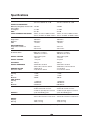
1
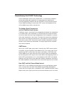
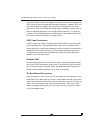
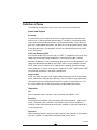
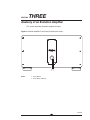
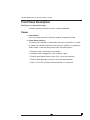
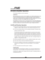
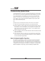
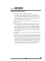
EVOLUTION
EVOLUTION
400,
AMPLIFIERS
302
AND
403
THREE-CHANNEL
600,
402
AND
OWNER’S
STEREO
900
MONAURAL
REFERENCE
Evolution 302, 402, 403, 400, 600 and 900 Power Amplifiers
Owner’s Reference, v08.0
Krell Industries, Inc.
45 Connair Road
Orange, CT 06477-3650 USA
TEL 203-298-4000
FAX 203-891-2028
E-MAIL [email protected]
WEBSITE http://www.krellonline.com
This product complies with the EMC directive (89/336/EEC) and the low-voltage directive
(73/23/EEC).
IMPORTANT SAFETY INSTRUCTIONS
1.
Read Instructions.
2.
Keep these Instructions.
3.
Heed all Warnings.
4.
Follow all Instructions.
5.
Do not use this apparatus near water.
6.
Clean only with a dry cloth.
7.
Do not install near any heat sources such as radiators, heat registers, stoves, or other apparatus (including amplifiers) that produce heat.
8.
Unplug this apparatus during lightning storms or when unused for long periods of time.
9.
Refer all servicing to qualified service personnel. Servicing is required when the apparatus
has been damaged in any way, such as a power-supply cord or plug is damaged, liquid has
been spilled or objects have fallen into the apparatus, the apparatus has been exposed to
rain or moisture, does not operate normally, or has been dropped.
10. An Evolution amplifier must be placed on a firm, level surface where it is not exposed to dripping or splashing.
11. The ventilation grids on the top of every Evolution amplifier, the ventilation grids on the back of
the Evolution 302 and 400 amplifiers, and the space underneath every Evolution amplifier must
be unobstructed at all times during operation. Do not place flammable material above or
beneath an Evolution amplifier.
12. Before making connections to an Evolution amplifier, ensure that the power is off and other components are in mute or stand-by mode. Make sure all cable terminations are of the highest quality, free from frayed ends, short circuits, or cold solder joints.
13. THERE ARE NO USER SERVICEABLE PARTS INSIDE AN EVOLUTION AMPLIFIER.
Please contact Krell if you have questions not addressed in this guide.
This product is manufactured in the United States of America. Krell® is a registered trademark of Krell Industries, Inc., and is restricted for use by
Krell Industries, Inc., its subsidiaries, and authorized agents. CAST™, Evolution CAST™, and Krell Current Mode™ are trademarks of Krell
Industries, Inc. All other trademarks are registered to their respective companies.
© 2007 by Krell Industries, Inc. All rights reserved .
P/N 309888
Contents
List of Illustrations, page 4
A Letter from Dan D’Agostino, page 5
SECTION ONE: Evolution Amplifier Features and Technology, page 6
Features, Revolutionary Krell CAST Technology,
Definition of Terms
SECTION TWO: Unpacking and Placement, page 11
Opening the Evolution Amplifier Shipping Carton
SECTION THREE: Anatomy of the Evolution Amplifier, page 13
Front Panel Description, and Back Panel Description
SECTION FOUR: Connecting an Evolution Amplifier to Your System, page 22
CAST Connections, Balanced Connections, Single-ended Connections,
Evolution DC Protection Circuitry/Using Tube Preamplifiers, Connection Steps
SECTION FIVE: Evolution Amplifier Operation, page 24
On/Off and Stand-by Operation
SECTION SIX: Troubleshooting System Noise, page 25
How to Evaluate Amplifier Operation, Error Codes
SECTION SEVEN: Questions and Answers, page 27
WARRANTY, page 28
RETURN AUTHORIZATION PROCEDURE, page 30
SPECIFICATIONS, page 31
3
List of Illustrations
Figure 1, page 13
Evolution Amplifier Front Panel
Figure 2, page 15
Evolution 302 Stereo Back Panel
Figure 3, page 16
Evolution 402 Stereo Amplifier Back Panel
Figure 4, page 17
Evolution 403 Three-channel Amplifier Back Panel
Figure 5, page 18
Evolution 400 Monaural Amplifier Back Panel
Figure 5, page 19
Evolution Monaural Amplifier Back Panel
4
A Letter from Dan D’Agostino
Dear Audio Enthusiast,
Thank you for your purchase of a Krell Evolution Series amplifier.
Evolution Series amplifiers continue my quest for amplifiers that deliver absolute
truth in music reproduction. Active Cascode Topology is a unique circuit technique
that minimizes distortion by applying from 2 to 3 times more active devices to
each gain stage. The attributes of this topology is shared throughout the Evolution
Series amplifiers.
Krell amplifiers are best known for their ability to drive any loudspeaker to sound
its best, without regard to impedance or efficiency. I believe that linearity, an
amplifier’s ability to output an exact duplicate of the input signal, is the ultimate
measure of that amplifier’s work. At Krell, I drive amplifier designs toward the common goal of linearity, through the rigorous application of Krell design principles
that focus our efforts on four major performance factors: distortion, bandwidth,
output impedance, and current capability. The Evolution Series amplifiers are a
synthesis of these factors.
The Evolution Series amplifiers use Evolution CAST technology, for superior performance and very low noise.
I hope that you enjoy your new Evolution Series amplifier.
Sincerely,
Daniel D’Agostino
Chief Executive Officer
5
SECTION
ONE
Evolution Amplifier Features and Technology
This section describes the innovative features and technology of the Evolution
Series amplifiers, and defines CAST and other key terms used in this reference.
There are six amplifier models in the Evolution Series: the 302 Stereo Power
Amplifier, the 402 Stereo Power Amplifier, the 403 Three-channel Power Amplifier,
the 400 Monaural Power Amplifier, the 600 Monaural Power Amplifier, and the 900
Monaural Power Amplifier. The compact chassis of the 400 Monaural Power
Amplifier contains all of the high power, wide bandwidth, and low noise characteristics designed into all Evolution Series amplifiers.
Features
Evolution Series amplifiers are designed with a signal path that incorporates Krell
Current Mode and CAST circuitry.
All amplifiers feature massive power supplies. The power supply makes use of
extensive electrical and magnetic shielding to keep radiated interference out of
critical amplifier circuits.
The Evolution 302 design utilizes a 3000 VA power supply. The Evolution 402 and
Evolution 600 are equipped with a 5000 VA power supply, and the Evolution 403
and Evolution 900 house 6000 VA power supplies.
Internal high-current line conditioning circuitry filters RF noise on the AC mains, as
well as compensating for asymmetrical power waveforms and DC on the mains.
Advanced microprocessor control monitors critical operational parameters. Output
current, DC offset, rail voltages, and operating temperature are all continuously
monitored.
6
Revolutionary Krell CAST Technology
Current Audio Signal Transmission, termed CAST, is a revolutionary method of
connecting analog audio components for unparalleled sonic performance.
Innovative engineering combines the new Krell CAST circuitry with existing Krell
Current Mode technology to create entire CAST systems that reproduce music
with incredible range, tonality, and precision.
The Voltage Signal Transmission
and the Traditional Audio System
Traditionally, signal is transmitted in the voltage domain between two components.
In an audio system, each component is a discrete entity with unique characteristics that act upon the musical signal independently. Each component is unaware
of the other components in the system. The cables that connect the components
also have their own electrical characteristics, which affect the sonic presentation
of the entire system. CAST transmission unifies individual components and interconnects into an electrically-linked whole. The original signal remains unaltered
from source to speaker.
CAST Basics
Here is how a CAST audio system works. Internally, each CAST source transfers,
or amplifies, current using Krell Current Mode circuitry. This current signal is then
output using CAST circuitry. When the signal is received by a CAST input, Krell
Current Mode circuitry again takes over until the signal reaches the loudspeaker.
By maintaining the musical signal in the current domain from beginning to end, an
entire CAST system behaves as if it is one component. With CAST, circuit board
properties and signal transmission aberrations between components are eliminated. Cable impedances and their effects on the transmitted signal are non-existent.
How CAST and Krell Current Mode Interact
While CAST is a new method of transferring the musical signal between components, its origin stems from Krell Current Mode, the technology developed to
transfer the musical signal within a component. CAST combined with Krell Current
Mode circuitry takes signal transmission to the next evolutionary level. In essence,
7
continued
(SECTION ONE: Evolution Amplifier Features and Technology continued)
Krell Current Mode maintains the integrity of the signal within the component and
CAST preserves the transmitted signal between components. Together, CAST and
Krell Current Mode technologies unify separate Krell components into a single
global circuit. Krell Current Mode technology enjoys bandwidth increases up to an
order of magnitude greater than their voltage based counterparts. This dramatic
increase in circuit bandwidth delivers near perfection in the audible band that typically suffers from phase distortions in voltage circuits.
CAST Cable Construction
A CAST system uses cables manufactured by Krell and other manufacturers specially licensed by Krell. Thin and flexible CAST cables are constructed with the
same build quality as other Krell components and are aesthetically matched to the
components that Krell manufactures. An all-metal body and locking connectors
with gold contacts are part of the standard no-compromise specification developed for every CAST cable made.
Evolution CAST
By employing revolutionary current mirror circuitry, the Evolution amplifier components raises CAST technology to another level. This advanced use of the technology increases the linearity, transient speed, and bandwidth of the Evolution components while reducing the distortion by an order of magnitude.
The Best Musical Performance
When you operate a CAST system, you will hear significant improvements in every
performance area: speed, precision, dynamic range, depth and width of the sound
stage, transient impact, tonal balance, harmonic distortion, and more. The goal for
CAST is the same company goal used for all Krell products. Krell strives for the
delivery of the best performance of a musical event for you, using the full expression of technology to date.
8
Definition of Terms
The following are definitions of key terms used in this owner’s reference:
Inputs and Outputs
Balanced
A symmetrical input or output circuit that has equal impedance from both input
terminals to a common ground reference point. The industry standard for professional and sound recording installations, balanced connections have 6 dB more
gain than single-ended connections and allow the use of long interconnect cables.
Balanced connections are completely immune to induced noise from the system
or the environment.
CAST and Evolution CAST
Krell Current Audio Signal Transmission, or CAST, is a proprietary Krell circuit technology for connecting analog components, transmitting the audio waveform
between components in the current domain rather than in the voltage domain. The
speed and bandwidth provided by Krell CAST and its circuitry update, Evolution
CAST, yield accurate, realistic music reproduction, enabling connected components to perform as if they are all part of a single circuit. CAST and Evolution CAST
are balanced connections, and reject induced noise.
Single-ended
A two-wire input or output circuit. Single-ended connections are not recommended for connections requiring long cable runs. Use care when using single-ended
connections, because the ground connection is made last and broken first. Turn
the system off/on prior to making or breaking single-ended connections.
Operation
Off
When the power status indicator is not illuminated, the amplifier is off.
Stand-by
A low-power-consumption status that keeps the audio and power supply circuits
at idle. The power status indicator is illuminated in red, when the amplifier is in
stand-by mode. Krell recommends leaving the amplifier in stand-by mode when it
is not playing music.
Operation
When the power button is pressed, and the power status indicator is illuminated in
blue, the amplifier is in operational mode and ready to play music.
9
continued
(SECTION ONE: Definition of Terms continued)
Technology
Active Cascode Topology
A unique circuit technique that minimizes distortion by applying from 2 to 3 times
more active devices to each gain stage thereby reducing the load on individual
devices and improving circuit-wide linearity.
Krell Current Mode
A proprietary Krell circuit topology in which the audio gain stages of a component
operate in the current domain rather than the voltage domain. This unique technology provides the component with exceptional speed, and a wide bandwidth.
10
TWO
SECTION
Unpacking and Placement
This section describes the procedures for safely unpacking and placing your
Evolution amplifier. The amplifier and accessories are shipped in 1 carton. The
dimensions of the amplifier are shown in the specifications section starting on
page 31.
Two people are needed to remove the Evolution amplifier from its shipping box
safely and easily.
Opening the Evolution Amplifier Shipping Carton
1. Open the shipping carton and remove the top layer of foam. The carton contains these items:
1 Evolution amplifier chassis
1 20 amp AC power cord
1 12 VDC (12 V trigger) cable
1 Packet containing the Quick Setup Guide and the warranty registration card
2. Orient the shipping box so that one person stands at the front of the amplifier
and one person stands at the back of the amplifier. Both people need to grab
a pair of the cardboard handle cutouts (one pair located at the front of the
amplifier and one pair located at the back of the amplifier) and simultaneously
lift the amplifier straight up, out of the carton. Bend and lift with your knees,
not your back.
3. Place the amplifier in a safe location, and remove the protective plastic wrapping.
Note
Save all packing materials. If you need to ship the Evolution amplifier in future, repack
the unit in its original packaging to prevent shipping damage.
11
continued
(SECTION TWO: Unpacking and Placement continued)
Placement
Before you install an Evolution amplifier into your system, please follow the guidelines in this section to select a location for your component. This will facilitate a
clean, trouble-free installation.
Place the amplifier on a firm, level surface, away from excessive heat, humidity, or
moisture. Each Evolution amplifier requires at least two inches (5 cm) of clearance
on each side and at least eight inches (20 cm) of clearance above the component
to provide adequate ventilation.
If you place the amplifier in a closed cabinet, you may need to modify shelf spacing or use small fans to increase ventilation. When the front and back of a cabinet
are open, the air space between the chassis and shelf must be unobstructed.
Place the amplifier(s) as close to the loudspeakers as possible. While Evolution
CAST technology permits long interconnect cable lengths, keep loudspeaker
cable lengths to a minimum.
AC Power Guidelines
The Evolution amplifier requires a dedicated AC circuit rated at a minimum of 20
amps. Do not use extension cords, multiple AC adapters, or AC power strips.
Note
Do not operate the Evolution amplifiers with any device designed to alter or condition
AC power.
12
SECTION
THREE
Anatomy of an Evolution Amplifier
This section describes Evolution amplifier functions.
Figure 1 Evolution Amplifier Front Panel (Evolution 402 shown)
Power
1 Power Button
2 Power Status Indicator
13
continued
(SECTION THREE: Anatomy of an Evolution Amplifier continued)
Front Panel Description
See Figure 1 on the previous page
Evolution amplifier front panel functions are described below:
Power
1 Power Button
Press this button to place the Evolution amplifier in operational mode.
2 Power Status Indicator
The power status indicator is illuminated in red when the amplifier is in standby mode. The indicator illuminates in blue when the amplifier is in operational
mode. If there is no illumination, please check the following items:
—The power cord is connected to the amplifier
—The power cord is plugged into a live AC power supply
—The back panel power breaker switch (10) is set to the on position
—The back panel backlight switch (8) is set to the on/ext position
—There is no 12 VDC controller connected to the EXT IN connector
14
Figure 2 Evolution 302 Stereo Amplifier Back Panel
Outputs
Inputs
Remote
Power
3
4
5
6
7
8
9
10
Loudspeaker Binding Posts
CAST Inputs
Single-ended Inputs
Balanced Inputs
12 VDC Out/In (12 V Trigger)
Backlight Control
IEC Power Cord Receptacle
Power Breaker Switch
15
continued
Figure 3 Evolution 402 Stereo Amplifier Back Panel
Outputs
Inputs
Remote
Power
3
4
5
6
7
8
9
10
Loudspeaker Binding Posts
CAST Inputs
Single-ended Inputs
Balanced Inputs
12 VDC Out/In (12 V Trigger)
Backlight Control
IEC Power Cord Receptacle
Power Breaker Switch
16
(SECTION THREE: Anatomy of an Evolution Amplifier continued)
Figure 4 Evolution 403 Multi-channel Amplifier Back Panel
Outputs
Inputs
Remote
Power
3
4
5
6
7
8
9
10
Loudspeaker Binding Posts
CAST Inputs
Single-ended Inputs
Balanced Inputs
12 VDC Out/In (12 V Trigger)
Backlight Control
IEC Power Cord Receptacle
Power Breaker Switch
17
continued
Figure 5 Evolution 400 Monaural Amplifier Back Panel
Outputs
Remote
Power
3
4
5
6
7
8
9
10
Loudspeaker Binding Posts
CAST Input
Single-ended Input
Balanced Input
12 VDC Out/In (12 V Trigger)
Backlight Control
IEC Power Cord Receptacle
Power Breaker Switch
18
Figure 6 Evolution Monaural Amplifier Back Panel (Evolution 600 shown)
Outputs
Inputs
Remote
Power
3
4
5
6
7
8
9
10
Loudspeaker Binding Posts
CAST Input
Single-ended Input
Balanced Input
12 VDC Out/In (12 V Trigger)
Backlight Control
IEC Power Cord Receptacle
Power Breaker Switch
19
(SECTION THREE: Anatomy of an Evolution Amplifier continued)
Back Panel Description
See Figures 2, 3, 4, 5, and 6 on the previous pages
The amplifier back panel provides access to the input and output connections,
12 V trigger inputs and outputs, and the AC power connection and switch. Back
panel features and their descriptions follow:
Outputs
3 Loudspeaker Binding Posts (one pair per channel)
Each channel has one positive and one negative binding post. They accept
spade lugs only.
Inputs
4 CAST Inputs (one per channel)
These are CAST inputs with 4-pin bayonet connectors, for use with Krell
CAST-equipped preamplifiers and components.
5 Single-ended Inputs (one per channel)
These are single-ended analog inputs with RCA connectors.
6 Balanced Inputs (one per channel)
These are balanced analog inputs with XLR connectors.
20
continued
Remote Connections
7 12 VDC In/Out (12 V Trigger)
The 12 V trigger allows you to turn the Evolution amplifier on or to stand-by
from other components.
Out. The output sends 12 VDC (12 V trigger) power on/off signals to other Krell
components and other devices that incorporate a 12 V trigger, allowing whole
systems or parts of systems to be easily controlled remotely. Mono 3.5 mm
connectors are used in the following configuration: Tip = +12 V, Sleeve = GND.
Notes
When an Evolution amplifier is in the operational mode, the 12 V trigger provides 12 Volts
of DC output. When the amplifier is in the stand-by mode or off, the DC output is
0 Volts. A maximum of 30 mA is available from the 12 V trigger output.
Consult the owner's reference of the components used in a custom installation to take
full advantage of the remote capabilities of an Evolution amplifier.
8 Backlight Control
Ext In. Connect a 12 V trigger to the Ext In input connector to turn off the
power status indicator (2) using a remote control. The switch must be set to
On/Ext, in order for this to function (see below).
On/Ext. This activates the power status indicator. (This is the factory default
position.)
Off. This turns off the power status indicator, during normal operation. The
power status indicator remains illuminated for ten seconds after the power button is pressed.
Power
9 IEC Power Cord Receptacle
The power receptacle is for use with the provided 20 amp AC power cord. Use
only the power cord supplied with your Evolution amplifier.
10 Power Breaker Switch
Place this switch in the up position to put the amplifier in stand-by mode.
Place the switch in the down position to turn off the amplifier.
21
SECTION
FOUR
Connecting an Evolution Amplifier
to Your System
This section describes Evolution amplifier connections. Each Evolution amplifier
channel has a CAST 4-pin connector, a balanced input via an XLR connector, a
single-ended RCA connector, and a pair of loudspeaker binding posts. The rear
panel also has 12 VDC trigger input and outputs, and a backlight remote trigger
input. All inputs and outputs are located on the Evolution amplifier back panel.
Maintain the correct left/right orientation, when hooking up your system.
CAST Connections
Krell recommends using its proprietary Krell CAST system for unparalleled sonic
performance for connections between the Evolution amplifier and other CASTequipped components. Krell CAST uses flexible interconnecting cables that can
be drawn through tight spaces and concealed.
Balanced Connections
The Evolution amplifier also offers balanced operation. The circuitry and connections associated with balanced operation not only can minimize sonic loss but
also are immune to induced noise, especially for installations using long cables.
XLR Pin Configuration
Pin 1
Pin 2
Pin 3
Ground
Non-inverting (0 ) (hot)
Inverting (180 ) (cold)
O
O
Single-ended Connections
Each Evolution amplifier channel has one single-ended input. If connecting a vacuum
tube preamplifier, use the single-ended inputs only (see below). Connect the u-shaped jumpers between pins 1 and 3 of the XLR connectors when using single-ended
inputs.
22
continued
Evolution DC Protection Circuitry/Using Tube Preamplifiers
The high DC output of tube preamplifiers may exceed the active DC protection
circuitry of the Evolution amplifiers. Excessive DC level in a signal can damage
amplifiers, loudspeakers, or both. The single-ended inputs of the Evolution amplifiers are capacitor-coupled and DC does not pass through. Therefore, if connecting a tube preamplifier, use the single-ended inputs only. For more information
about DC protection circuitry features, see Error Codes on page 26.
Connection Steps
Position the amplifier where you intend to use it in your system.
The following steps describe how to connect an Evolution amplifier to your system:
1. Turn off all power sources and components before connecting inputs and outputs.
2. Neatly arrange and organize wiring to and from the Evolution amplifier and all
components. Separate AC wires from audio cables to prevent hum or other
unwanted noise from being introduced into the system.
3. Connect the outputs of your preamplifier to the appropriate CAST (4), balanced
(6), or single-ended inputs (5) on the Evolution amplifier.
Note
Connect the u-shaped jumpers between pins 1 and 3 of the XLR connectors when
using single-ended inputs.
4. Connect the loudspeaker cables to the loudspeaker binding posts (7) on the
Evolution amplifier. The binding posts accept spade lugs only. Take care to
observe the correct polarity when making connections: The positive (+) output
connects to the positive input of the loudspeaker. The negative (-) output connects to the negative input of the loudspeaker.
5. Connect the supplied AC power cord to the AC power cord receptacle (9).
6. Plug the AC power cord into AC power.
Note
Use only the power cord provided with the Evolution amplifier to make the connection
to AC power. Operation with a power cord other than the one supplied by Krell could
induce noise, limit current, or otherwise impair the ability of the amplifier to perform
optimally.
23
SECTION
FIVE
Evolution Amplifier Operation
The Evolution amplifiers are easy to operate.
IMPORTANT
When powering up any system, turn the amplifier on last. When powering down, turn
it off first. This will prevent any turn-on and turn-off thumps in your loudspeakers.
Always mute or fully attenuate the preamplifier level when switching sources. Do not
change input connections to the amplifier when the amplifier is on.
Krell amplifiers have large reserves of clean power that can safely drive loudspeakers
to higher sound pressure levels than other amplifiers. Use care when setting high playback levels, and lower the volume level at the first sign of loudspeaker distress.
On/Off and Stand-by Operation
1. Move the back panel power breaker switch (10) to the up position to place the
amplifier in stand-by mode. The power status indicator (2) illuminates in red.
2. Press the silver power button (1) on the amplifier front panel. The power status
indicator (2) illuminates in blue.
The initial power-up phase lasts approximately 30 seconds from the moment
the back panel power breaker switch is placed in the up position. If the power
button is pressed during this period, the power status indicator flashes blue for
the remainder of the initial power-up phase. When the initial power-up phase is
complete, the power indicator illuminates in blue and is no longer flashing. The
amplifier is in the operational mode.
3. With the preamplifier muted or its volume completely lowered, select a source.
4. Increase the volume control to the desired listening level.
5. To return the amplifier to stand-by, press the power button on the front panel.
The power status indicator turns red, and the amplifier is in the stand-by
mode.
It is now safe to place the rest of the system in stand-by.
Powering Off
Krell recommends leaving Evolution amplifiers in the stand-by mode between listening sessions. Turn the amplifier off using the power breaker switch (10), and
disconnect the amplifier from AC power when the system is not being used for an
extended period of time.
24
SECTION
SIX
Troubleshooting System Noise
AC grounding becomes critical when connecting high-performance audio components. When you mix and match high-performance audio components, each with
its own ground potential, a low frequency hum may occur in one or both loudspeakers. This often occurs when introducing a new component into a system.
If this happens when you place the Evolution amplifier into your system, follow
these simple troubleshooting steps.
Note
During these steps, the back panel power breaker switch remains in the on position.
1. Check that all input and output connections are of sound construction.
2. With the amplifier in stand-by mode, remove the interconnect cables, then turn
the amplifier on. If the hum disappears, turn the amplifier into stand-by mode
again, and reinsert one of the interconnect cables. Turn the amplifier back on.
Repeat this process for each cable.
3. If the hum reappears with one or both interconnect cables reinserted, the cable
needs to be checked.
4. If the interconnect cables are sound, you may be experiencing a ground loop.
Please contact your authorized Krell dealer, distributor, or Krell for suggestions
on how to eliminate the ground loop.
How to Evaluate Amplifier Operation
The amplifiers are protected by a series of non-intrusive circuits that constantly
evaluate the amplifier’s operation. This circuitry protects against damaging DC
input or output, and short circuits. The protection circuitry in an Evolution amplifier
is designed to prevent damage to the amplifiers or loudspeakers caused by other
defective components, faulty wiring, system mishandling, or amplifier failure.
25
(SECTION SIX: Troubleshooting continued)
Error Codes
In the event of a problem, the power status indicator (2) will flash error code(s) in
red. Errors are identified by a sequence of 3, 4, or 5 flashes. There is a pause
between codes, and in the case where there is only one error code, the same
code is repeated.
Diagnostic Code
Possible Condition
Course of Action
3 flashes
Excessive current draw
Check loudspeaker and
cables for short circuits.
If you are driving more
than one loudspeaker
per channel, check that
the combined load does
not drop below 2 Ohms.
The power breaker
switch must be shut off
to reset the fault condition.
4 flashes
Excessive temperature
Allow the amplifier to
cool, and increase ventilation. If the problem
persists, please call the
factory.
5 flashes
Excessive DC at input
Check the preamplifier
output and source outputs for excessive DC
voltage.
If you are using a vacuum
tube preamplifier, use
only the single-ended
inputs, as they are
capacitor coupled.
26
SECTION
SEVEN
Questions and Answers
Q. Should I leave my Evolution amplifier on at all times?
A. For maximum amplifier performance, leave the back panel power breaker
switch on at all times. This places the amplifier in stand-by mode. Evolution
amplifiers are designed to be powered on and off from stand-by, using the
front panel power button. This eliminates “cold start” degradation. The amplifier will operate at full performance within minutes.
Q. When I turn on the amplifier there is a loud hum through the loudspeakers.
What should I do?
A. When a new component is introduced, a low frequency hum may occur in one
or both loudspeakers. Check all input and output connections and cables,
making sure they are of sound construction. See Troubleshooting System
Noise, on page 25. If the interconnects and cables are sound, you may be
experiencing a ground loop. This can often be easily eliminated. Please contact your authorized Krell dealer, distributor, or Krell for suggestions on how to
solve this problem.
Q. My loudspeakers are rated for 150 Watts. Are the Evolution models too powerful for them?
A. No. A loudspeaker seldom is damaged from overdriving. More often, damage
occurs when an amplifier that lacks sufficient power is asked to handle heavy
demand situations such as high playback levels. These amplifiers may have
very high 8 Ohm power ratings, but in heavy demand situations they can be
driven into clipping (in which high power, high frequency harmonics go to the
loudspeakers, due to loss of amplifier power). Clipping can damage loudspeakers. Avoid damage to your loudspeakers by reviewing your loudspeaker’s specifications, and exercise caution in heavy demand situations.
27
Warranty
Krell products have a limited warranty. Amplifiers, preamplifiers, preamp/processors,
and receivers carry a limited warranty of five years for parts and labor on circuitry.
Loudspeakers carry a limited warranty of five years for parts and labor. CD and
DVD players carry a limited warranty of five years for parts and labor on circuitry,
and three years for parts and labor on mechanical parts.
Should the product fail to perform at any time during the warranty, Krell will repair it
at no cost to the owner, except as set forth in this warranty.
This warranty does not apply to damage caused by acts of God or nature.
This warranty shall be in lieu of any other warranty, expressed or implied, including,
but not limited to, any implied warranty of merchantability or fitness for a particular
purpose. There are no warranties which exceed beyond those described in this
document, if the product does not perform as warranted herein, the owner’s sole
remedy shall be repair. In no event will Krell be liable for incidental or consequential
damages arising from purchase, use, or inability to use the product, even if Krell
has been advised of the possibility of such damages.
IMPORTANT
The single-ended inputs on the Evolution amplifiers are cap-coupled. Use these
inputs whenever you are connecting a tube preamplifier.
Proof of purchase in the form of a bill of sale or receipted invoice substantiating
that the product is within the warranty period must be presented to obtain warranty
service. The warranty begins on the date of the original retail purchase, as noted on
the bill of sale or receipted invoice from an authorized Krell dealer or distributor.
Previously owned equipment, when re-purchased from an authorized Krell dealer or
distributor, has the balance of the original warranty, based on the original date of
manufacture. Krell dealers and distributors are not authorized to sell current products on the Internet. Current products purchased via the Internet do not have any
transferrable warranty.
The warranty for a Krell product is valid only in the country to which it was originally
shipped, through the authorized Krell distributor for that country, and at the factory.
There may be restrictions on or changes to the Krell warranty because of regulations within a specific country. Please check with your distributor for a complete
understanding of the warranty in your country.
28
continued
If the product is serviced by a distributor who did not import the unit, there may be
a charge for service, even if the product is within the warranty period.
Freight to the factory is your responsibility. Return freight within the United States
(U.S.A.) is included in the warranty. If you have purchased your Krell product outside the U.S.A. and wish to have it serviced at the factory, all freight and associated
charges to the factory are your responsibility. Krell will pay return freight to the
U.S.A.-based freight forwarder of your choice. Freight and other charges to ship the
product from the freight forwarder to you are also your responsibility.
Krell is not responsible for any damage incurred in transit. Krell will file claims for
damages as necessary for a product damaged in transit to the factory. You are
responsible for filing claims for shipping damages during the return shipment.
Krell does not supply replacement parts and/or products to the owner of the product. Replacement parts and/or products will be furnished only to the distributor
performing service on this product on an exchange basis only; any parts and/or
products returned to Krell for exchange become the property of Krell.
No expressed or implied warranty is made for any Krell product damaged by accident, abuse, misuse, natural or personal disaster, or unauthorized modification.
Any unauthorized voltage conversion, disassembly, component replacement,
perforation of chassis, updates, or modifications performed to the product
will void the warranty.
The operating voltage of the product is determined by the factory and can only be
changed by an authorized Krell distributor or at the factory. The voltage for this
product in the U.S.A. cannot be changed until six months from the original purchase date.
In the event that Krell receives a product for warranty service that has been modified in any way without Krell authorization, all warranties on that product will be
void. The product will be returned to original factory layout specifications at the
owner’s expense before it is repaired. All repairs required after the product has
been returned to original factory specifications will be charged to the customer, at
current parts and labor rates.
All operational features, functions, and specifications and policies are subject to
change without notification.
To register your product for warranty benefits, please complete and return the
Warranty Registration Card enclosed in the shipping box within 15 days of purchase. Thank you.
29
Return Authorization Procedure
How to Expedite Service
If you believe there is a problem with your component, please contact your dealer, distributor, or the Krell factory to discuss the problem before you return the
component for repair. To expedite service, you may wish to complete and e-mail
the Service Request Form in the Service section of our website at:
http://www.krellonline.com
To contact the Krell Service Department:
TELL
FAX
E-MAIL
203-298-4020, Monday-Friday
9:00 AM to 5:00 PM EST
203-795-2287
[email protected]
WEBSITE http://www.krellonline.com
How to Return a Product
To return a product to Krell, please follow this procedure so that we may serve
you better:
1. Obtain a Return Authorization Number (R/A number) and shipping address
from the Krell Service Department.
2. Insure and accept all liability for loss or damage to the product during shipment
to the Krell factory and ensure that all freight (shipping) charges are prepaid.
The product may also be hand delivered if arrangements with the Service
Department have been made in advance. Proof of purchase will be required for
warranty validation at the time of hand delivery.
IMPORTANT
Use the original packaging to ensure the safe transit of the product to the factory,
dealer, or distributor. Krell may, at its discretion, return a product in new packaging and
bill the owner for such packaging if the product received by Krell was boxed in nonstandard packaging or if the original packaging was so damaged that it was unusable.
If Krell determines that new packaging is required, the owner will be notified before
the product is returned.
How to Purchase Additional Packing
To purchase additional packing, please contact your authorized Krell dealer, distributor, or the Krell Service Department for assistance.
30
Specifications
Measurement
Evolution 302 Stereo Amplifier
Evolution 402 Stereo Amplifier
FREQUENCY RESPONSE
20 Hz to 20 kHz +0, –0.10 dB
<0.5 Hz to 180 kHz +0, –3 dB
20 Hz to 20 kHz +0, –0.18 dB
<0.5 Hz to 120 kHz +0, –3 dB
Wideband, unweighted, referred to full
power output
“A” weighted
>107 dB
>106 dB
>117 dB
>116 dB
GAIN
25.5 dB
25.4 dB
TOTAL HARMONIC DISTORTION
<0.02% at 1 kHz, at 300 W, 8 Ohms <0.02% at 1 kHz, at 400 W, 8 Ohms
<0.15% at 20 kHz, at 300 W, 8 Ohms <0.15% at 20 kHz, at 400 W, 8 Ohms
SIGNAL-TO-NOISE RATIO
INPUT IMPEDANCE
100 kOhms
200 kOhms
75 Ohms
100 kOhms
200 kOhms
70 Ohms
Single-ended or balanced
CAST
2.60 V rms
2.60 mA rms
3.04 V rms
3.04 mA rms
OUTPUT POWER
300 W rms at 8 Ohms
600 W rms at 4 Ohms
1200 W rms at 2 Ohms
400 W rms at 8 Ohms
800 W rms at 4 Ohms
1600 W rms at 2 Ohms
139 V peak-to-peak
49 V rms
160 V peak-to-peak
57 V rms
Single-ended
Balanced
CAST
INPUT SENSITIVITY
All channels driven
OUTPUT VOLTAGE
OUTPUT CURRENT
35 A peak
37 A peak
SLEW RATE
120 V/µs
100 V/µs
OUTPUT IMPEDANCE
<0.040 Ohms at 20 Hz
<0.053 Ohms, 20 Hz to 20 kHz
<0.055 Ohms at 20 Hz
<0.064 Ohms, 20 Hz to 20 kHz
DAMPING FACTOR
>200 at 20 Hz
>150, 20 Hz to 20 kHz
>145 at 20 Hz
>125, 20 Hz to 20 kHz
150 W
320 W
3400 W
370 W
570 W
3800 W
Stand-by
Idle
Maximum
510 BTU/hr.
1100 BTU/hr.
5500 BTU/hr.
890 BTU/hr.
1300 BTU/hr.
6400 BTU/hr.
INPUTS
2 single-ended via RCA connector
2 balanced via XLR connector
2 CAST via 4-pin bayonet connector
2 single-ended via RCA connector
2 balanced via XLR connector
2 CAST via 4-pin bayonet connector
OUTPUTS
2 pairs Krell binding posts
2 pairs Krell binding posts
DIMENSIONS
17.3 in. W x 9.8 in. H x 20.7 in. D
438 mm W x 248 mm H x 525 mm D
17.3 in. W x 9.8 in. H x 22.1 in. D
438 mm W x 248 mm H x 550 mm D
138 lb., 62.4 kg
120 lb., 54.3 kg
150 lb., 67.9 kg
135 lb., 61.1 kg
Referred to 8 Ohms
POWER CONSUMPTION
Stand-by
Idle
Maximum
HEAT OUTPUT
WEIGHT
Shipping
Unit only
All operational features, functions, specifications, and policies are subject to change without notification.
31
(Specifications continued)
Measurement
Evolution 403 3-channel Amplifier
FREQUENCY RESPONSE
20 Hz to 20 kHz +0, –0.18 dB
<0.5 Hz to 120 kHz +0, –3 dB
Evolution 400 Monaural Amplifier
SIGNAL-TO-NOISE RATIO
Wideband, unweighted, referred to full
power output
“A” weighted
>106 dB
GAIN
25.4 dB
TOTAL HARMONIC DISTORTION
<0.02% at 1 kHz, at 400 W, 8 Ohms
<0.15% at 20 kHz, at 400 W, 8 Ohms
>116 dB
INPUT IMPEDANCE
Single-ended
Balanced
CAST
100 kOhms
200 kOhms
70 Ohms
INPUT SENSITIVITY
Single-ended or balanced
CAST
3.04 V rms
3.04 mA rms
OUTPUT POWER
400 W rms at 8 Ohms
800 W rms at 4 Ohms
1600 W rms at 2 Ohms
OUTPUT VOLTAGE
160 V peak-to-peak
57 V rms
OUTPUT CURRENT
37 A peak
SLEW RATE
100 V/µs
OUTPUT IMPEDANCE
<0.055 Ohms at 20 Hz
<0.064 Ohms, 20 Hz to 20 kHz
DAMPING FACTOR
>145 at 20 Hz
>125, 20 Hz to 20 kHz
Referred to 8 Ohms
POWER CONSUMPTION
Stand-by
Idle
Maximum
370 W
570 W
5000 W
HEAT OUTPUT
Stand-by
Idle
Maximum
1270 BTU/hr.
1950 BTU/hr.
7700 BTU/hr.
INPUTS
3 single-ended via RCA connector
3 balanced via XLR connector
3 CAST via 4-pin bayonet connector
OUTPUTS
3 pairs Krell binding posts
DIMENSIONS
17.3 in. W x 9.8 in. H x 26.1 in. D
438 mm W x 248 mm H x 662 mm D
WEIGHT
Shipping
Unit only
190 lb., 86 kg
175 lb., 79.2 kg
All operational features, functions, specifications, and policies are subject to change without notification.
continued
32
(Specifications continued)
Measurement
Evolution 600 Monaural Amplifier
Evolution 900 Monaural Amplifier
FREQUENCY RESPONSE
20 Hz to 20 kHz +0, –0.18 dB
<0.5 Hz to 120 kHz +0, –3 dB
20 Hz to 20 kHz +0, –0.18 dB
<0.5 Hz to 120 kHz +0, –3 dB
Wideband, unweighted, referred to full
power output
“A” weighted
>110 dB
>113 dB
>119 dB
>122 dB
GAIN
25.4 dB
25.4 dB
TOTAL HARMONIC DISTORTION
<0.02% at 1 kHz, at 600 W, 8 Ohms <0.02% at 1 kHz, at 900 W, 8 Ohms
<0.15% at 20 kHz, at 600 W, 8 Ohms <0.15% at 20 kHz, at 900 W, 8 Ohms
SIGNAL-TO-NOISE RATIO
INPUT IMPEDANCE
100 kOhms
200 kOhms
70 Ohms
100 kOhms
200 kOhms
70 Ohms
Single-ended or balanced
CAST
3.72 V rms
3.72 mA rms
4.55 V rms
4.55 mA rms
OUTPUT POWER
600 W rms at 8 Ohms
1200 W rms at 4 Ohms
2400 W rms at 2 Ohms
900 W rms at 8 Ohms
1800 W rms at 4 Ohms
3600 W rms at 2 Ohms
OUTPUT VOLTAGE
196 V peak-to-peak
69 V rms
240 V peak-to-peak
85 V rms
Single-ended
Balanced
CAST
INPUT SENSITIVITY
OUTPUT CURRENT
49 A peak
60 A peak
SLEW RATE
100 V/µs
90 V/µs
OUTPUT IMPEDANCE
<0.030 Ohms, 20 Hz to 20 kHz
<0.023 Ohms, 20 Hz to 20 kHz
DAMPING FACTOR
>270, 20 Hz to 20 kHz
>350, 20 Hz to 20 kHz
260 W
410 W
3800 W
440 W
650 W
5000 W
Stand-by
Idle
Maximum
890 BTU/hr.
1400 BTU/hr.
5500 BTU/hr.
1500 BTU/hr.
2200 BTU/hr.
7700 BTU/hr.
INPUTS
1 single-ended via RCA connector
1 balanced via XLR connector
1 CAST via 4-pin bayonet connector
1 single-ended via RCA connector
1 balanced via XLR connector
1 CAST via 4-pin bayonet connector
OUTPUTS
1 pair Krell binding posts
1 pair Krell binding posts
DIMENSIONS
17.3 in. W x 9.8 in. H x 22.1 in. D
17.3 in. W x 9.8 in. H x 26.1 in. D
438 mm W x 248 mm H x 560 mm D 438 mm W x 248 mm H x 662 mm D
Referred to 8 Ohms
POWER CONSUMPTION
Stand-by
Idle
Maximum
HEAT OUTPUT
WEIGHT
Shipping
Unit only
150 lb., 67.9 kg
135 lb., 61.1 kg
190 lb., 86 kg
175 lb., 79.2 kg
All operational features, functions, specifications, and policies are subject to change without notification.
33
EVOLUTION
400,
AMPLIFIERS
302
AND
403
THREE-CHANNEL
600,
402
AND
OWNER’S
STEREO
900
MONAURAL
REFERENCE
V08.0
KRELL
45
INDUSTRIES,
CONNAIR
ORANGE,
TELL:
CT
06477-3650
203-298-4000
E-MAIL:
INC.
ROAD
•
FA X :
USA
203-891-2028
[email protected]
h t t p : / / w w w. k r e l l o n l i n e . c o m