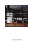
1
KAV–2250
THE LEADER IN AUDIO ENGINEERING
Stereo Power Amplifier
KAV–3250
Three-channel Power Amplifier
Instructions for Use
Owner’s Reference
KAV–2250
Stereo Power Amplifier
KAV–3250
Three-channel Power Amplifier
Instructions for Use
Krell Industries, Inc.
45 Connair Road
Orange, CT 06477-3650 USA
TEL 203-799-9954
FAX 203-891-2028
E-MAIL [email protected]
WEBSITE http://www.krellonline.com
v 01.2
This product complies with the EMC directive (89/336/EEC) and the low-voltage directive (73/23/EEC).
WARNINGS
The amplifier must be placed on a firm, level surface where it is not exposed to dripping or splashing.
The ventilation grids on the top and bottom of the amplifier must be unobstructed at all times during operation.
Do not place flammable material above or beneath the amplifier.
Contact your authorized Krell dealer, distributor, or Krell before using any devices designed to alter or stabilize the AC power for the KAV–2250 and the KAV–3250.
Before connecting the KAV–2250 and the KAV–3250, make sure the amplifier is turned off and any output
device (such as a preamplifier) is in mute or stand-by mode. Make sure all cable terminations are of the
highest quality and free from frayed ends, short circuits, or cold solder joints.
Use only one input to each amplifier channel at a time.
Make sure that only one switch on an input switch bank is in the up (on) position at one time.
THERE ARE NO USER SERVICEABLE PARTS INSIDE ANY KRELL PRODUCT.
Please contact your authorized Krell dealer, distributor, or Krell if you have any questions not addressed in
this reference manual.
This product is manufactured in the United States of America. Krell® is a registered trademark of Krell Industries, Inc., and is restricted for use by Krell
Industries, Inc., its subsidiaries, and authorized agents. Multi Amp Throughput™ and Krell Current Mode™ are trademarks of Krell Industries, Inc. All other
trademarks and tradenames are registered to their respective companies.
© 2001
by Krell Industries, Inc. All rights reserved
P/N 305573
Contents
Page
INTRODUCTION
1
DEFINITION OF TERMS
2
UNPACKING
4
PLACEMENT
5
AC Power Guidelines
5
FRONT PANEL DESCRIPTION
7
BACK PANEL DESCRIPTION
9
CONNECTING THE AMPLIFIER TO YOUR SYSTEM
Input and Output Connections
AMPLIFIER OPERATION
On/Off and Operation
Using a Dedicated Wall Switch
11
11
13
13
13
TROUBLESHOOTING SYSTEM NOISE
14
RECONFIGURATION OPTIONS FOR THE KAV–2250 AND KAV–3250
15
To Safely Access the Input Switch Banks
Amplifier Factory Default Settings
Reconfiguring the Amplifier for MAT Operation
Reconfiguring the Amplifier for Bridged Operation
Example of a Connection Scenario: Multi-power Mode
15
18
18
21
22
QUESTIONS AND ANSWERS
23
WARRANTY
24
RETURN AUTHORIZATION PROCEDURE
25
SPECIFICATIONS
KAV–2250
KAV–3250
26
27
Krell KAV–2250 and KAV–3250
iii
Illustrations
Page
FIGURE 1
The KAV–2250 Front Panel
6
FIGURE 2
The KAV–3250 Front Panel
6
FIGURE 3
The KAV–2250 Back Panel
8
FIGURE 4
The KAV–3250 Back Panel
8
FIGURE 5
Amplifier Factory Default Settings
16
FIGURE 6
Reconfiguring the KAV–2250 for MAT Operation
17
FIGURE 7
Reconfiguring the KAV–3250 for MAT Operation
17
FIGURE 8
Reconfiguring the KAV–2250 for Bridged Operation
20
FIGURE 9
Reconfiguring the KAV–3250 for Bridged Operation
20
iv
Krell KAV–2250 and KAV–3250
Introduction
Thank you for your purchase of the Krell KAV–2250 Stereo Power Amplifier or the KAV–
3250 Three-channel Power Amplifier.
The KAV–2250 and KAV–3250 amplifiers provide substantial two- and three-channel
output power that delivers realistic music reproduction at an exceptional value. These
amplifiers can be customized with two optional system configurations: Multi Amp
Throughput (MAT) and bridged operation. These configurations provide a wider range of
power outputs and connection options. Both the KAV–2250 and KAV–3250 amplifiers
have balanced and single-ended inputs, for complete compatibility with other
components. The KAV–2250 and KAV–3250 amplifiers can be operated using the 12
VDC trigger on other components. Either amplifier integrates seamlessly into home
theater or whole-house systems.
This reference manual contains important information on placement, installation, and
operation of the KAV–2250 and KAV–3250 amplifiers. Please read this information
carefully. A thorough understanding of these details helps ensure satisfactory operation
and long life for your amplifier and related system components.
Krell KAV–2250 and KAV–3250
1
Definition of Terms
Following are the definitions of key terms used in your owner’s reference manual.
CONFIGURATIONS
Bridging
A method of linking two amplifier channels by distributing the speaker load between the
positive binding posts. Bridging the channels quadruples the power rating at 8 Ohms.
Bridged configurations should not be used with loads under 4 Ohms.
Krell Multi Amp Throughput (MAT)
An internal configuration option that sends the same music signal to all amplifier
channels using one balanced or single-ended connection. MAT reduces installation
complexity and cabling requirements in systems containing multiple amplifiers. MAT
also allows a variety of connection scenarios, including powering loudspeakers that
have two sets of binding posts and independently powering multiple pairs of stereo
loudspeakers to extend the listening environment throughout your home.
INPUT AND OUTPUT CONNECTIONS
Balanced
A symmetrical input or output circuit that has equal impedance from both input terminals
to a common ground reference point. The industry standard for professional and sound
recording installations, balanced connections have 6 dB more gain than single-ended
connections and allow the use of long interconnect cables. Balanced connections are
completely immune to induced noise from the system or the environment.
Single-ended
A two-wire input or output circuit. Use care when using single-ended connections as the
ground connection is made last and broken first. Turn the system off prior to making or
breaking single-ended connections. Single-ended connections are not recommended for
connections requiring long cable runs.
2
Krell KAV–2250 and KAV–3250
Definition of Terms, continued
OPERATION
Off
When the back panel power switch is in the down (off) position and the red stand-by
LED turns off, the component is off.
Stand-by Mode
When the AC power cord is plugged into the wall and the back panel power switch is in
the up (on) position, the red stand-by LED illuminates, indicating that the component is
in stand-by mode. This low power consumption status keeps the audio and regulator
circuits at idle. Krell recommends leaving the component in the stand-by mode when it
is not playing music.
Operational Mode
From the stand-by mode, when the power button on the front panel is pressed and the
blue power indicator illuminates, the component is in the operational mode and ready to
play music.
TECHNOLOGY
Krell Current Mode
A proprietary Krell circuit topology in which the audio gain stages of a component
operate in the current rather than voltage domain. This unique technology provides the
component with exceptional speed and a wide bandwidth.
Krell KAV–2250 and KAV–3250
3
Unpacking
1. Open the shipping box and remove the top layer of foam. You see these items:
1 amplifier unit (packed in foam end-caps)
1 IEC connector (AC power) cord
1 12 VDC output (12 V trigger) cable
1 T-15 Torx wrench
KAV–2250 fuses:
2 AGC-12 (12-amp)
or
KAV–3250 fuses:
3 AGC-12 (12-amp)
1 packet containing the owner’s reference manual
and the warranty registration card.
2. Locate the cutouts in the foam end caps.
3. Slip hands under cutouts and lift the amplifier straight out of the box.
4. Place the amplifier in a safe location and remove the protective plastic wrapping.
Notes
If any of these items are not included in the shipping box, please contact your
authorized Krell dealer, distributor, or Krell for assistance.
Save all packing materials. If you ship your amplifier in the future, repack the unit in its
original packaging to prevent transit damage. See Return Authorization Procedure,
on page 25, for more information.
The KAV–2250 weighs 64 lbs. and the KAV–3250 weighs 68 lbs. It may be more
convenient for two people to lift the amplifier out of the shipping box.
4
Krell KAV–2250 and KAV–3250
Placement
Before you integrate your new amplifier into your system, please review the following
guidelines to choose the location for the component. This will facilitate a clean, troublefree installation.
The amplifier requires at least two inches (5 cm) of clearance on each side and at least
two inches (5 cm) of clearance above and below the component to provide adequate
ventilation.
The amplifier does not require any type of special rack or cabinet for installation. For the
dimensions of your amplifier see Specifications, on pages 26 and 27.
Place the amplifier as close to the loudspeakers as possible and keep the loudspeaker
cable length to a minimum. Loudspeaker cable adds impedance to the load the amplifier
must drive, regardless of the cable’s gauge. Krell amplifiers drive the lowest
impedances with ease, but long loudspeaker cables reduce the maximum power that is
delivered to the loudspeakers.
AC POWER GUIDELINES
Krell recommends operating the amplifier from a dedicated 15-amp AC power line.
Please contact your authorized Krell dealer, distributor, or Krell before using any
devices designed to alter or stabilize the AC power for the KAV–2250 and KAV–3250.
`
Power Cord
The KAV–2250 and KAV–3250 should be operated only with the power cord supplied.
Krell KAV–2250 and KAV–3250
5
Figure 1 The KAV–2250 Front Panel
KAV–2250
1
3
2
Figure 2 The KAV–3250 Front Panel
KAV–3250
1
3
2
1 Power Button
2 Stand-by LED
3 Power Indicator
6
Krell KAV–2250 and KAV–3250
Front Panel Description
See Figures 1 and 2 on page 6
The front panel on the KAV–2250 and the KAV–3250 provides power on and indicates
operating status.
1 Power Button
Use this button to switch the power between the stand-by and the operational modes
and also to switch the 12 VDC output (12 V trigger) on and off.
2 Stand-by LED
The red stand-by LED illuminates when the AC power cord is plugged into the wall and
the back panel power switch is in the up (on) position.
3 Power Indicator
The blue power indicator illuminates when the amplifier is in the operational mode.
Krell KAV–2250 and KAV–3250
7
Figure 3 The KAV–2250 Back Panel
6
4
11
12
12VDC
INPUT 2
INPUT 1
30 mA max. OUT
KAV–2250
IN
Two-channel
Power Amplifier
KRELL INDUSTRIES, INC.
45 CONNAIR ROAD
ORANGE, CT 06477-3650
USA
OUTPUT 1
OUTPUT 2
AGC-12
AGC-12
50/60 Hz
MADE IN USA
NO USER SERVICEABLE PARTS INSIDE
BRIDGE
8
10
8
10
14
13
Figure 4 The KAV–3250 Back Panel
7
5
11
12
12VDC
INPUT 3
INPUT 2
INPUT 1
30 mA max. OUT
KAV–3250
IN
Three-channel
Power Amplifier
OUTPUT 3
AGC-12
AGC-12
KRELL INDUSTRIES, INC.
45 CONNAIR ROAD
ORANGE, CT 06477-3650
USA
OUTPUT 1
OUTPUT 2
AGC-12
50/60 Hz
MADE IN USA
NO USER SERVICEABLE PARTS INSIDE
BRIDGE
9
10
Balanced Inputs
4 Inputs 1-2
5 Inputs 1-3
Single-Ended Inputs
6 Inputs 1-2
7 Inputs 1-3
8
9
10
9
Amplifier Channel
Outputs
8 Outputs 1-2
9 Outputs 1-3
Fuses
10 AGC-12 Fuses
14
10
13
Remote Connections
11 12 VDC Remote Power Out
12 12 VDC Remote Power In
Power
13 IEC Power Connector
14 Back Panel Power Switch
Krell KAV–2250 and KAV–3250
Back Panel Description
See Figures 3 and 4 on page 8
The back panel on the KAV–2250 and the KAV–3250 provides connections for all inputs
and outputs, remote connection input and output links, and the AC power supply. See
Reconfiguration Options for the KAV–2250 and the KAV–3250, on pages
15-22, for information on optional system configurations and amplifier channel output
connections.
Balanced Inputs
4 Inputs 1-2
The KAV–2250 has two channel inputs for output devices with balanced XLR
connectors.
5 Inputs 1-3
The KAV–3250 has three channel inputs for output devices with balanced XLR
connectors.
Single-ended Inputs
6 Inputs 1-2
The KAV–3250 has two channel inputs for output devices with single-ended RCA
connectors.
7 Inputs 1-3
The KAV–3250 has three channel inputs for output devices with single-ended RCA
connectors.
Amplifier Channel Outputs
8 Outputs 1-2
The KAV–2250 has two amplifier channel outputs. The loudspeaker binding post
terminals accept spade lugs, bare wire, or pins. Use the red terminal for the positive
connection and the black terminal for the negative connection.
9 Outputs 1-3
The KAV–3250 has three amplifier channel outputs. The loudspeaker binding post
terminals accept spade lugs, bare wire, or pins. Use the red terminal for the positive
connection and the black terminal for the negative connection.
IMPORTANT
Tighten loudspeaker binding posts by hand only.
Krell KAV–2250 and KAV–3250
9
Back Panel Description, continued
Fuses
10 AGC-12 Fuses
The AGC-12 Amp loudspeaker fuses protect the amplifier against short circuits at the
amplifier outputs.
Back Panel Remote Connections
11 12 VDC Remote Power Out
The amplifier is equipped with an output that sends 12 VDC power on/off
(12 V trigger) signals to other Krell components and other devices that incorporate
a 12 V trigger.
12 12 VDC Remote Power In
The amplifier is equipped with an input that receives 12 VDC power on/off (12 V trigger)
signals from other Krell components and other devices that incorporate a 12 V trigger.
This allows you to turn the amplifier on and off using a Krell or other component in a
custom installation.
Notes
When the component is in the operational mode, the 12 VDC Out provides 12 V of DC
output. When the component is in the stand-by mode or off, the DC output is 0 V.
12 VDC Out (12 V trigger) current is limited to 30 mA.
Consult the owner’s manual of each component used in a custom installation to take full
advantage of the amplifier’s remote capability.
Power
13 IEC Power Connector
The amplifier is equipped with a standard female IEC power connector, for use with the
provided AC power cord.
14 Back Panel Power Switch
Use this switch to turn the amplifier from off to the stand-by mode.
10
Krell KAV–2250 and KAV–3250
Connecting the Amplifier to Your System
INPUT AND OUTPUT CONNECTIONS
The amplifier is equipped with balanced and single-ended inputs.
Krell recommends using balanced interconnect cables. Balanced interconnect cables
not only can minimize sonic loss but are also immune to induced noise, especially with
installations using long cables. Balanced connections have 6 dB more gain than singleended connections. When level matching is critical, please keep this gain value in mind.
The amplifier is shipped with shorting pins in the XLR inputs. These pins should remain
in the XLR inputs if the amplifier is operating in the single-ended mode. When the
shorting pin is inserted, pins 1 (lower left) and 3 (top) are shorted together. Remove the
shorting pins to connect the amplifier for balanced operation.
The XLR pin configuration is described below:
Pin 1 Shield (ground)
Pin 2 Non-inverting (hot) (0°)
Pin 3 Inverting (cold) (180°)
Follow these steps to connect the amplifier to your system.
1. Make sure all power sources and components are off before connecting inputs and
outputs.
2. Neatly organize the wiring between the amplifier and all system components.
Separate AC wires from audio cables to prevent hum or other unwanted noise from
being introduced into the system.
3. Connect the interconnect cables from your output device to the amplifier inputs using
the balanced or single-ended inputs located on the back panel: (4) and (6) on the
KAV–2250 or (5) and (7) on the KAV–3250. The balanced inputs use three-pin XLR
connectors; the single-ended inputs use RCA connectors.
IMPORTANT
Use only one input to each amplifier channel at a time.
Krell KAV–2250 and KAV–3250
11
Connecting the Amplifier, continued
4. Connect the loudspeaker cables to the amplifier channel output binding posts
located on the back panel, (8) on the KAV–2250 or (9) on the KAV–3250.
The binding post terminals accept spade lugs, bare wire, or pins. Use the red
terminal for the positive connection and the black terminal for the negative
connection.
IMPORTANT
Tighten loudspeaker binding posts by hand only.
5. Plug the end of the AC power cord into the IEC power connector.
The amplifier is now ready for operation. See Amplifier Operation, on page 13. You
can also reconfigure the amplifier for Multi Amp Throughput or bridged operation. See
Reconfiguration Options for the KAV–2250 and the KAV–3250, on page 15.
12
Krell KAV–2250 and KAV–3250
Amplifier Operation
ON/OFF AND OPERATION
When powering up your system, turn amplifiers on last. When powering down your
system, turn amplifiers off first. The procedures for amplifier operation follow.
1. Plug the AC power cord into the AC power wall receptacle.
2. Push the back panel power switch (14) up (on). The red stand-by LED (2)
illuminates.
3. Press the power button (1) on the front panel. The blue power indicator (3)
illuminates and you hear a click.
There will be a brief delay before the component can be put in the operational mode
after the back panel power switch is first pushed up.
Krell recommends leaving the amplifier in the stand-by mode unless you will not be
playing music for a long time.
IMPORTANT
Always turn the amplifier off before changing input connections, and mute or fully
attenuate the preamplifier level when switching sources.
The amplifier has tremendous reserves of power and safely drives loudspeakers to
extremely high sound pressure levels. However, use care when setting high playback
levels and lower the volume level at any sign of loudspeaker distress.
USING A DEDICATED WALL SWITCH
The amplifier can also be powered on from an AC wall receptacle with a dedicated
switch, rather than from the front panel power button. Please contact your authorized
Krell dealer, distributor, or Krell for more information before you connect the amplifier to
a dedicated AC wall outlet with a switch.
Krell KAV–2250 and KAV–3250
13
Troubleshooting System Noise
When you mix and match high-performance audio components, each with its own
ground potential, a low frequency hum may occur in one or all loudspeakers. If this
happens when you place the amplifier into your system, follow these simple
troubleshooting steps:
1. Check that all input and output connections are of sound construction.
2. With the amplifier off, remove all the interconnect cables, then turn the amplifier
on. If the hum disappears, turn the amplifier off and reinsert one of the
interconnect cables. Turn the amplifier back on.
3. If the hum reappears with the interconnect cable reinserted, the cable may need
to be replaced. Turn the amplifier off and connect a different interconnect cable to
the same location. Turn the amplifier back on.
4. If the hum disappears with the interconnect cable reinserted, that cable most
likely is sound.
5. Turn the amplifier off, disconnect the interconnect cable, and re-connect one of
the other interconnect cables.
6. Repeat steps 3 through 5 until you have checked each interconnect cable
individually.
7. If all the interconnect cables appear to be sound, and if you still have hum, you
may be experiencing a ground loop. Please contact your authorized Krell dealer,
distributor, or Krell for suggestions on how to eliminate it.
14
Krell KAV–2250 and KAV–3250
Reconfiguration Options for the KAV–2250
and KAV–3250
There are a number of options for reconfiguring the amplifier output:
Multi Amp Throughput (MAT) is an internal connection option for the amplifier that lets
you send the same music signal to all amplifier channels using one balanced or singleended connection. MAT reduces installation complexity and cabling requirements in
systems containing multiple amplifiers.
Bridging allows you to reconfigure two channels to operate as one combined amplifier
channel. The bridged amplifier channels deliver 1,000 Watts into an 8 Ohm load. The
remaining unbridged amplifier channel on the KAV–3250 can be connected to a
separate loudspeaker.
To reconfigure the amplifier for MAT or for bridged operation you need to remove the
top cover of the amplifier and access the input switch banks.
IMPORTANT
Removing the cover of the amplifier to reconfigure for MAT or for bridged operation is
the ONLY instance you are authorized to remove the cover of ANY Krell component
without voiding your Warranty. For more information on product limitations and
restrictions, see Warranty, on page 24.
TO SAFELY ACCESS THE INPUT SWITCH BANKS
Before reconfiguring the amplifier, please read the following important instructions to
safely remove the amplifier cover and access the input switch banks to reconfigure the
KAV–2250 or KAV–3250.
Tool needed: T-15 Torx wrench
1. Unplug the AC power cord from AC power.
2. Krell suggests removing jewelry before reconfiguring your amplifier. Rings,
necklaces, bracelets, and other metal jewelry can conduct an electrical charge.
3. Using the T-15 Torx wrench, remove the 12 screws that secure the amplifier cover.
4. Carefully remove the cover.
5. Locate the green input circuit board, which has white input switches and red input
switch banks, at the rear of the amplifier
Krell KAV–2250 and KAV–3250
15
Figure 5 Amplifier Factory Default Settings
KAV–2250
Input Circuit Board
MT1
Channel 1 Input
O 1
N
S1
Bridge
Channel 2 Input
1
2
J5
S2
S3
O 1
N
2
J6
KAV–3250
Input Circuit Board
MT1
Channel 1 Input
S1
O 1
N
2
Channel 2 Input
Bridge
1
3
J7
S4
S2
O 1
N
2
Channel 3 Input
3
J8
S3
O 1
N
2
3
J9
Switch Up (On)
Switch Down (Off)
Bridge Switch Up (On)
Bridge Switch Down (Off)
O 1
N
2
KAV–2250 Input Switch Bank
O
N
1
2
3
KAV–3250 Input Switch Bank
16
Krell KAV–2250 and KAV–3250
Figure 6 Reconfiguring the KAV–2250 for MAT Operation
Send One Input Signal
to Both Output Channels via Input 1
Input Circuit Board
MT1
Channel 1 Input
S1
O 1
N
Bridge
Channel 2 Input
1
2
J5
S2
S3
O 1
N
2
J6
Figure 7 Reconfiguring the KAV–3250 for MAT Operation
Send One Input Signal
to All Three Output Channels via Input 1
Input Circuit Board
MT1
Channel 1 Input
S1
O 1
N
2
Channel 2 Input
Bridge
1
3
J7
S4
S2
O 1
N
2
Channel 3 Input
3
J8
S3
O 1
N
2
3
J9
Switch Up (On)
Switch Down (Off)
Bridge Switch Up (On)
Bridge Switch Down (Off)
O 1
N
2
KAV–2250 Input Switch Bank
O
N
1
2
3
KAV–3250 Input Switch Bank
Krell KAV–2250 and KAV–3250
17
Reconfiguration Options, continued
Accessing the Input Switch Banks, continued
6. Reconfigure your amplifier, using the scenarios described below.
7. After the component is configured, replace the cover and, using the T-15 Torx
wrench, secure all 12 cover screws.
IMPORTANT
Operating the amplifier without the cover properly replaced and secured may void your
Warranty.
AMPLIFIER FACTORY DEFAULT SETTINGS
See Figure 5 on page 16
The KAV–2250 amplifier is shipped with input switch banks set to the following factory
defaults:
1. For input switch bank 1: switch 1 up (on), switch 2 down (off).
2. For input switch bank 2: switch 1 down (off), switch 2 up (on).
The KAV–3250 amplifier is shipped with input switch banks set to the following factory
defaults:
1. For input switch bank 1: switch 1 up (on), other switches down (off).
2. For input switch bank 2: switch 2 up (on), other switches down (off).
3. For input switch bank 3: switch 3 up (on), other switches down (off).
RECONFIGURING THE AMPLIFIER FOR MAT OPERATION
Reconfiguring the KAV–2250 for MAT: Send One Input Signal
to Both Output Channels via Input 1
See Figure 6 on page 17
To send the signal from a source device connected to input 1:
1. Push switch 1 up (on) for both input switch banks.
2. Push switch 2 down (off) for both input switch banks.
18
Krell KAV–2250 and KAV–3250
Reconfiguration Options, continued
Reconfiguring the KAV–2250 for MAT: Send One Input Signal
to Both Output Channels via Input 2
Not illustrated
To send the signal from a source device connected to input 2:
1. Push switch 2 up (on) for both input switch banks.
2. Push switch 1 down (off) for both input switch banks.
Reconfiguring the KAV–3250 for MAT: Send One Input Signal
to All Three Output Channels via Input 1
See Figure 7 on page 17
To send the signal from a source device connected to input 1:
1. Push switch 1 up (on) for all input switch banks.
2. Push switches 2 and 3 down (off) for all input switch banks.
Reconfiguring the KAV–3250 for MAT: Send One Input Signal
to All Three Output Channels via Any Input
Not illustrated
You can send the signal from any of the inputs, depending on your preference,
for example:
To send the signal from a source device connected to input 2:
1. Push switch 2 up (on) for all input switch banks.
2. Push switches 1 and 3 down (off) for all input switch banks.
or
To send the signal from a source device connected to input 3:
1. Push switch 3 up (on) for all input switch banks.
2. Push switches 1 and 2 down (off) for all input switch banks.
Krell KAV–2250 and KAV–3250
19
Figure 8 Reconfiguring the KAV–2250 for Bridged Operation
Bridge Channel 1 and 2
Input Circuit Board
MT1
Channel 1 Input
S1
O 1
N
Bridge
Channel 2 Input
1
2
J5
S2
S3
O 1
N
2
J6
Figure 9 Reconfiguring the KAV–3250 for Bridged Operation
Bridge Channel 1 and 2
Input Circuit Board
MT1
Channel 1 Input
S1
O 1
N
2
Channel 2 Input
Bridge
1
3
J7
S4
S2
O 1
N
2
Channel 3 Input
3
J8
S3
O 1
N
2
3
J9
Switch Up (On)
Switch Down (Off)
Bridge Switch Up (On)
Bridge Switch Down (Off)
O 1
N
2
KAV–2250 Input Switch Bank
O
N
1
2
3
KAV–3250 Input Switch Bank
20
Krell KAV–2250 and KAV–3250
Reconfiguration Options, continued
Connecting the Amplifier Reconfigured for MAT
1. Connect the cable from your source device to the balanced or single-ended input
you have selected to receive the signal. (For example, if you use the switch settings
shown in Figure 6 your source device is connected to input 1.)
2. Connect each amplifier channel output to a separate loudspeaker.
RECONFIGURING THE AMPLIFIER FOR BRIDGED OPERATION
Reconfiguring the KAV–2250 or the KAV–3250 to Bridge Channels 1 and 2
See Figures 8 and 9 on page 20
To send the signal from a source device connected to input 1,
with channels 1 and 2 bridged:
1. For input switch bank 1, push switch 1 up (on).
2. For input switch bank 2, push switch 1 up (on).
3. Push the bridge switch up (on) between input switch banks 1 and 2.
Notes
Amplifier channels 1 and 2 may be bridged. Channel 3 on the KAV–3250 cannot be
bridged.
The unbridged channel on the KAV–3250 may be connected to a separate loudspeaker
for normal operation.
Connecting the Amplifier Reconfigured for Bridged Operation
1. Connect the cable from the input device to the balanced or single-ended input you
have selected to receive the signal.
2. Connect the positive loudspeaker lead to the red binding post on the corresponding
amplifier channel marked “BRIDGE +.” Connect the negative loudspeaker lead to the
red binding post on the amplifier channel marked “BRIDGE -.”
IMPORTANT
Tighten binding posts by hand only.
Krell KAV–2250 and KAV–3250
21
Reconfiguration Options, continued
EXAMPLE OF A CONNECTION SCENARIO: MULTI-POWER MODE
Multi-power mode is a possible connection scenario that uses the amplifier’s Multi Amp
Throughput (MAT) feature. With multi-power mode, you can reconfigure the amplifier to
independently power multiple pairs of stereo loudspeakers and extend the listening environment throughout your home. When the amplifier is reconfigured for MAT, each channel
powers an individual loudspeaker, with one amplifier dedicated to driving outputs to the left
loudspeakers and one amplifier driving outputs to the right loudspeakers.
The diagram below illustrates a multi-power mode connection scenario:
Left Speakers
–
+
–
Gym (L)
+
+
–
–
–
+
+
Patio (L)
+
Kitchen (L)
–
Left Amplifier
Kitchen (R)
+
–
–
–
+
+
–
+
Right Amplifier
Patio (R)
Gym (R)
+
+
–
–
Right Speakers
22
Krell KAV–2250 and KAV–3250
Questions and Answers
Q. Should I turn the amplifier off when not playing music?
A. No. Leave the amplifier in stand-by when not playing music. The stand-by mode
avoids cold starts as well as minimizes heat output and power consumption. Krell
recommends turning the amplifier off if you plan to be away for a period of time, for
example, on vacation. See Amplifier Operation, on page 13.
Q. When I turn the amplifier on there is a loud hum through the loudspeakers. What
should I do?
A. When a new component is introduced, a low frequency hum may occur in one or
both loudspeakers. Check that all input and output connections and cables are of sound
construction. See Troubleshooting System Noise, on page 14. If the connections and
cables are sound, you may be experiencing a ground loop. This can often be easily
eliminated. Please contact your authorized Krell dealer, distributor, or Krell for
suggestions.
Q. When I connect the amplifier to my system using the single-ended inputs, a loud
buzz comes from my loudspeakers. What is it?
A. Check that the shorting pins for the amplifier are inserted into the XLR inputs (the unit
is shipped with the pins in place). When using the single-ended inputs, the shorting pins
must be inserted between pins 1 and 3 to keep external noise from corrupting the
signal. For more information, see Connecting the Amplifier to Your System, on page
11.
Q. Can I bridge all the channels on my KAV–3250 amplifier?
A. No. You can bridge two of the amplifier’s channels: 1 and 2. Channel 3 cannot be
bridged.
Q. Will I be able to use the amplifier without reconfiguring the channels for MAT or
bridged operation?
A. Yes. The amplifier is shipped from the factory ready to play music. The default
settings, see Figure 5, on page 16, allow you to connect each amplifier channel output
to a separate loudspeaker. MAT and bridging reconfigurations are optional.
Krell KAV–2250 and KAV–3250
23
Warranty
This Krell product has a limited warranty of five years for
parts and labor on circuitry. Should this product fail to perform at any time during the warranty, Krell will repair it at no
cost to the owner, except as set forth in this warranty.
Krell will pay return freight to the U.S.A.-based freight forwarder of your choice. Freight and other charges to ship the
unit from the freight forwarder to you are also your responsibility.
The warranty does not apply to damage caused by acts of
God or nature.
Krell is not responsible for any damage incurred in transit.
Krell will file claims for damages as necessary for units damaged in transit to the factory. You are responsible for filing
claims for shipping damages during the return shipment.
The warranty on this page shall be in lieu of any other warranty, expressed or implied, including, but not limited to, any
implied warranty of merchantability or fitness for a particular
purpose. There are no warranties which exceed beyond
those described in this document. If this product does not
perform as warranted herein, the owner’s sole remedy shall
be repair. In no event will Krell be liable for incidental or consequential damages arising from purchase, use, or inability
to use this product, even if Krell has been advised of the
possibility of such damages.
Proof of purchase in the form of a bill of sale or receipted
invoice substantiating that the unit is within the warranty
period must be presented to obtain warranty service. The
warranty begins on the date of the original retail purchase,
as noted on the bill of sale or receipted invoice from an
authorized Krell dealer or distributor. Previously owned
equipment, when re-purchased from an authorized Krell
dealer or distributor, has the balance of the original warranty, based on the original date of manufacture.
The warranty for Krell products is valid only in the country to
which they were originally shipped, through the authorized
Krell distributor for that country, and at the factory. There
may be restrictions on or changes to Krell’s warranty
because of regulations within a specific country. Please
check with your distributor for a complete understanding of
the warranty in your country.
If a unit is serviced by a distributor who did not import the
unit, there may be a charge for service, even if the product
is within the warranty period.
Freight to the factory is your responsibility. Return freight
within the United States (U.S.A.) is included in the warranty.
If you have purchased your Krell product outside the U.S.A.
and wish to have it serviced at the factory, all freight and
associated charges to the factory are your responsibility.
24
Krell does not supply replacement parts and/or products to
the owner of the unit. Replacement parts and/or products
will be furnished only to the distributor performing service on
this unit on an exchange basis only; any parts and/or products returned to Krell for exchange become the property of
Krell.
No expressed or implied warranty is made for any Krell
product damaged by accident, abuse, misuse, natural or
personal disaster, or unauthorized modification.
Any unauthorized voltage conversion, disassembly,
component replacement, perforation of chassis,
updates, or modifications performed to the unit will
void the warranty.
The operating voltage of this unit is determined by the factory and can only be changed by an authorized Krell distributor or at the factory. The voltage for this product in the
U.S.A. cannot be changed until six months from the original
purchase date.
In the event that Krell receives a product for warranty service that has been modified in any way without Krell authorization, all warranties on that product will be void. The product will be returned to original factory layout specifications at
the owner’s expense before it is repaired. All repairs
required after the product has been returned to original factory specifications will be charged to the customer, at current parts and labor rates.
All operational features, functions, and specifications and
policies are subject to change without notification.
To register your product for warranty benefits,
please complete and return the Warranty
Registration Card enclosed in the shipping box
within 15 days of purchase. Thank you.
Krell KAV–2250 and KAV–3250
Return Authorization
Procedure
If you believe there is a problem with your
component, please contact your dealer, distributor, or the Krell factory to discuss the
problem before you return the component for
repair. To expedite service, you may wish to
complete and e-mail the Service Request
Form in the Service Section of our website
at:
http://www.krellonline.com
To contact the Krell Service Department
TEL
203-799-9954
Monday-Friday
9:00 AM to 5:00 PM EST
FAX
203-799-9796
E-MAIL
[email protected]
WEBSITE
http://www.krellonline.com
PRODUCT NAME
MODEL NUMBER
SERIAL NUMBER
To return this product to Krell, please
follow this procedure so that we may
serve you better:
1. Obtain a Return Authorization Number
(R/A number) and shipping address
from the Krell Service Department.
2. Insure and accept all liability for loss of
or damage to this product during shipment to the Krell factory and prepay all
shipping charges. Please see the
Warranty page in this manual, concerning liability for shipping damage and
shipping charges.
This product may also be hand delivered if
arrangements with the Service Department
have been made in advance. Proof of purchase will be required for warranty validation at the time of hand delivery.
IMPORTANT
Use the original packaging to ensure safe
transit of this product to the dealer, distributor, or factory. Krell may, at its discretion,
return this product in new packaging and bill
the owner for such packaging if the product
received by Krell was boxed in non-standard packaging or if the original packaging
was so damaged that it was unuseable. If
Krell determines that new packaging is
required, the owner will be notified before
this product is returned.
To purchase additional packaging, please
contact your authorized Krell dealer, distributor, or the Krell Service Department.
Krell KAV–2250 and KAV–3250
25
Specifications
KAV–2250
FREQUENCY
RESPONSE
20 Hz to 20 kHz
0.25 Hz to 170 kHz
SIGNAL TO NOISE
RATIO
“A” WEIGHTED
>112 dB
TOTAL HARMONIC
DISTORTION (THD)
1 kHz
20 kHz
GAIN
25.7 dB
INPUT IMPEDANCE
100 kOhms
INPUT SENSITIVITY
2.32 Vrms
OUTPUT VOLTAGE
Peak to Peak
< 0.03%
< 0.20%
RMS
OUTPUT POWER
EACH CHANNEL
+0 dB, -0.09 dB
+0 dB,
-3 dB
127 V
45 V
8 Ohms
4 Ohms
8 Ohms
250 W
500 W
1000 W
POWER
CONSUMPTION
Standby
Idle
Max.
35 W
80 W
2000 W
INPUTS
2 single-ended via RCA connectors
BRIDGED
2 balanced via XLR connectors
OUTPUTS
2 amplifier channels via five-way binding posts
REMOTE CONNECTORS
12 VDC Out (12 V trigger) via a 3.5 mm connector
12 VDC In (12 V trigger) via a 3.5 mm connector
DIMENSIONS
17.3w x 5.6h x 17.1d in.
43.8w x 14.3h x 43.4d cm
WEIGHT
SHIPPING
74.0 lb., 33.5 kg
UNIT ONLY
64.0 lb., 29.0 kg
All operational features, functions, specifications, and policies are subject to change without notification.
26
Krell KAV–2250 and KAV–3250
Specifications
KAV–3250
FREQUENCY
RESPONSE
20 Hz to 20 kHz
0.25 Hz to 170 kHz
SIGNAL TO NOISE
RATIO
“A” WEIGHTED
>112 dB
TOTAL HARMONIC
DISTORTION (THD)
1 kHz
20 kHz
GAIN
25.7 dB
INPUT IMPEDANCE
100 kOhms
INPUT SENSITIVITY
2.32 Vrms
OUTPUT VOLTAGE
Peak to Peak
< 0.03%
< 0.20%
RMS
OUTPUT POWER
EACH CHANNEL
+0 dB, -0.09 dB
+0 dB,
-3 dB
127 V
45 V
8 Ohms
4 Ohms
8 Ohms
250 W
500 W
1000 W
POWER
CONSUMPTION
Standby
Idle
Max.
45 W
115 W
2000 W
INPUTS
3 single-ended via RCA connectors
BRIDGED
3 balanced via XLR connectors
OUTPUTS
3 amplifier channels via five-way binding posts
REMOTE CONNECTORS
12 VDC Out (12 V trigger) via a 3.5 mm connector
12 VDC In (12 V trigger) via a 3.5 mm connector
DIMENSIONS
17.3w x 5.6h x 17.1d in.
43.8w x 14.3h x 43.4d cm
WEIGHT
SHIPPING
78.0 lb., 35.3 kg
UNIT ONLY
68.0 lb., 30.8 kg
All operational features, functions, specifications, and policies are subject to change without notification.
Krell KAV–2250 and KAV–3250
27
Krell Industries, Inc.
45 Connair Road
Orange, CT 06477-3650 USA
TEL 203-799-9954
FAX 203-891-2028
E-MAIL [email protected]
WEBSITE http://www.krellonline.com
KAV–2250
Stereo Power Amplifier
KAV–3250
Three-channel Power Amplifier
v 01.2