1
AUDIO VIDEO SURROUND RECEIVER
VR-9080
KRF-X9090D
INSTRUCTION MANUAL
This instruction manual is for some models. Model availability and features (functions) may differ
depending on the country and sales area.
About the supplied remote control
Compared to standard remote controls, the remote control supplied with this receiver has several
operation modes. These modes enable the remote control to control other audio/video components. In
order to effectively use the remote control, it is important to read the operating instructions and obtain
a proper understanding of the remote control and how to switch its operation modes (etc.).
Using the remote control without completely understanding its design and how to switch the operation
modes may result in incorrect operations.
B60-5557-00 00 CS
*5557/01-09/EN
1
(K, P, Y)
OC
0504
05.7.16, 0:48 PM
Before applying the power
Caution : Read this page carefully to ensure safe
operation.
Units are designed for operation as follows.
How to use this manual
U.S.A. and Canada ........................................... AC 120 V only
Australia ........................................................... AC 240 V only
Europe ............................................................... AC 230 V only
Other countries .......... AC 110-120 / 220-240 V switchable*
This manual is divided into four sections, Preparations, Operations,
Remote Control, and Additional Information.
Shows you how to connect your audio and video components to the
receiver and prepare the surround processor.
Since this receiver works with all your audio and video components,
kindly follow the instructions in this manual for the correct connections.
* AC voltage selection
The AC voltage selector switch on the rear panel is set to the voltage
that prevails in the area to which the unit is shipped. Before
connecting the power cord to your AC outlet, make sure that the
setting position of this switch matches your line voltage. If not, it
must be set to your voltage in accordance with the following direction.
AC voltage selector switch
Move switch lever to
match your line voltage
with a small screwdriver
or other pointed tool.
Preparations
AC 220240V~
AC 110120V~
VOLTAGE SELECTOR
Operations
Shows you how to operate the various functions available on the
receiver.
Remote Control
Shows you how to operate other components using the remote control,
as well as a detailed explanation of all remote control operations. Once
you have registered your components with the proper setup codes, you’ll
be able to operate both this receiver and your other AV components (TV,
VCR, DVD player, CD player, etc.) using the remote control supplied with
this receiver.
Additional Information
Shows you additional information such as “In case of difficulty”
(troubleshooting) and “Specifications”.
For the U.S.A.
FCC WARNING
Note :
Our warranty does not cover damage caused by excessive line
voltage due to improper setting of the AC voltage selector switch.
Safety precautions
This equipment may generate or use radio frequency energy.
Changes or modifications to this equipment may cause harmful
interference unless the modifications are expressly approved in
the instruction manual. The user could lose the authority to
operate this equipment if an unauthorized change or modification
is made.
NOTE:
WARNING :
TO PREVENT FIRE OR ELECTRIC SHOCK,
DO NOT EXPOSE THIS APPLIANCE TO
RAIN OR MOISTURE.
CAUTION
RISK OF ELECTRIC SHOCK
DO NOT OPEN
CAUTION: TO REDUCE THE RISK OF ELECTRIC SHOCK, DO NOT
REMOVE COVER (OR BACK). NO USER-SERVICEABLE PARTS
INSIDE. REFER SERVICING TO QUALIFIED SERVICE PERSONNEL.
THE LIGHTNING FLASH WITH ARROWHEAD SYMBOL,
WITHIN AN EQUILATERAL TRIANGLE, IS INTENDED TO
ALERT THE USER TO THE PRESENCE OF UNINSULATED
“DANGEROUS VOLTAGE” WITHIN THE PRODUCT’S
ENCLOSURE THAT MAY BE OF SUFFICIENT MAGNITUDE
TO CONSTITUTE A RISK OF ELECTRIC SHOCK TO
PERSONS.
THE EXCLAMATION POINT WITHIN AN EQUILATERAL
TRIANGLE IS INTENDED TO ALERT THE USER TO THE
PRESENCE OF IMPORTANT OPERATING AND
MAINTENANCE (SERVICING) INSTRUCTIONS IN THE
LITERATURE ACCOMPANYING THE APPLIANCE.
This equipment has been tested and found to comply with the limits
for a Class B digital device, pursuant to Part 15 of the FCC Rules.
These limits are designed to provide reasonable protection against
harmful interference in a residential installation. This equipment
may cause harmful interference to radio communications, if it is not
installed and used in accordance with the instructions. However,
there is no guarantee that interference will not occur in a particular
installation. If this equipment does cause harmful interference to
radio or television reception, which can be determined by turning
the equipment off and on, the user is encouraged to try to correct
the interference by one or more of the following measures:
– – Reorient or relocate the receiving antenna.
– – Increase the separation between the equipment and receiver.
– – Connect the equipment into an outlet on a circuit different
from that to which the receiver is connected.
– – Consult the dealer or an experienced radio / TV technician for
help.
For the U.S.A.
Note to CATV system installer
This reminder is provided to call the CATV system installer's
attention to Article 820-40 of the NEC that provides guidelines for
proper grounding and, in particular, specifies that the cable ground
shall be connected to the grounding system of the building, as
close to the point of cable entry as practical.
As an ENERGY STAR® Partner, Kenwood
Corporation has determined that this
product meets the E NERGY S TAR ®
guidelines for energy efficiency. This
product can save energy. Saving energy
reduces air pollution and lowers utility bills.
2 EN
*5557/01-09/EN
2
05.7.16, 0:48 PM
Before applying the power
Contents
Caution : Read the pages marked
safe operation.
carefully to ensure
Basic remote control operations for other
components ....................................................... 42
Before applying the power ......................................................... 2
Safety precautions ...................................................................... 2
How to use this manual .............................................................. 2
Unpacking .................................................................................... 4
Preparing the remote control ...................................................... 4
Special features ........................................................................... 5
Names and functions of parts .................................................... 6
Remote
Control
Main unit ...................................................................................... 6
Remote control unit .................................................................... 7
Setting up the system ........................................ 8
Preparations
Connecting the terminals .................................. 9
Connecting a DVD player (6-channel input) ..... 10
Connecting audio components ........................ 11
Connecting video components ........................ 12
Digital connections .......................................... 13
Connecting video components
(COMPONENT VIDEO) .................................... 14
Connecting the speakers ................................. 15
PRE OUT connections ..................................... 16
Connecting to another room (ROOM B) ........ 17
Connecting the external IR Receiver
(For VR-9080) ................................................... 18
Connecting to the AV AUX jacks ..................... 19
Connecting the antennas ................................. 19
Additional
Information
Registering setup codes for other
components ..................................................... 42
Searching for your codes ................................. 42
Checking the codes ......................................... 42
Re-assigning device keys ................................ 43
Operating other components .......................... 43
Storing the remote control code of the other
components ..................................................... 44
Setup code chart .............................................. 45
Other components’ operations ....................... 49
In case of difficulty .......................................... 53
Specifications .................................................. 55
Preparing for surround sound ....................... 20
Before setting up the speakers ....................... 20
Setting up the speakers automatically (AUTO SETUP)
“Kenwood Room Acoustic Calibration” ............ 21
Setting up the speakers manually
(MANUAL SETUP) ........................................... 23
Other settings .................................................. 25
Normal playback .............................................. 27
Preparing for playback ..................................... 27
Listening to a source component .................... 27
Input level adjustment (analog sources only) .. 28
Adjusting the sound ......................................... 28
Recording .......................................................... 30
Recording audio (analog sources) ................... 30
Recording audio (digital sources) .................... 30
Recording video ............................................... 30
Listening to radio broadcasts ....................... 31
Operations
Tuning radio stations ....................................... 31
Presetting radio stations manually .................. 31
Receiving preset stations ................................ 32
Receiving preset stations in order (P.CALL) ... 32
Ambience effects ............................................. 33
Surround modes .............................................. 33
Surround play ................................................... 36
Virtual modes ................................................... 38
DVD 6-channel playback .................................. 38
Adjusting the sound ......................................... 39
Convenient functions ...................................... 41
Maintenance of the unit
When the front panel or case becomes dirty, wipe with a soft, dry
cloth. Do not use thinner, benzine, alcohol, etc. for these agents may
cause discoloration.
Display dimmer adjustment ............................ 41
Sleep timer ....................................................... 41
In regard to contact cleaner
Do not use contact cleaners because it could cause a malfunction. Be
specially careful not to use contact cleaners containing oil, for they
may deform the plastic component.
3 EN
*5557/01-09/EN
3
05.7.16, 0:48 PM
Before applying the power
Unpacking
Preparing the remote control
Unpack the unit carefully and make sure that all accessories are
present.
Loading the batteries
FM indoor antenna (1)
(For VR-9080))
(For KRF-X9090D)
1 Remove the cover.
2 Insert the batteries.
AM loop antenna (1)
3 Close the cover.
Remote control unit (1)
RC-R0918
Batteries (R03/AAA) (2)
• Insert two AAA-size (R03) batteries as indicated by the polarity
markings.
Microphone for SETUP (1)
(Cord length: approx. 5m (16 feet))
*AC plug adapter (1)
(For KRF-X9090D)
Operation
*Use to adapt the plug on
the power cord to the shape
of the wall outlet.
(Accessory only for regions
where use is necessary.)
If any accessories are missing, or if the unit is damaged or fails to operate,
notify your dealer immediately. If the unit was shipped to you directly,
notify your shipper immediately. Kenwood recommends that you retain
the original carton and packing materials in case you need to move or ship
the unit in the future.
Keep this manual handy for future reference.
When the standby indicator is lit, the power turns ON when you press the
RECEIVER ON key on the remote control. When the power comes ON,
press the key you want to operate.
Remote sensor
Operating range
(Approx.)
6 m (20 feet)
RECEIVER ON
Infrared ray system
Channel space switching
(Except for the U.S.A., Canada and Australia)
The space between radio channels has been set to the one that
prevails in the area to which the system is shipped. However, if the
current channel space setting does not match the setting in the area
where the system is to be used, for instance when you move from
area 1 or area 2 shown in the following table or vice versa, proper
reception of AM/FM broadcasts cannot be expected. In this case,
change the channel space setting in accordance with your area by
referring to the following table.
CHANNEL
Space Frequency
Area
1.
U.S.A., Canada and South
American countries
FM: 100 kHz
AM: 10 kHz
2.
Other countries
FM: 50 kHz
AM: 9 kHz
50us
AM 9kHz
FM50kHz
• When pressing more than one remote control key successively, press
the keys securely by leaving an interval of 1 second or more between
keys.
Notes
1. The supplied batteries may have shorter lives than ordinary batteries
due to use during operation checks.
2. When the remote-controllable distance gets shorter than before,
replace both batteries with new ones.
3. Placing the remote sensor in direct sunlight, or in direct light from a
high frequency fluorescent lamp may cause malfunction.
In such a case, change the location of the system installation to prevent
malfunction.
75us
AM 10kHz
FM100kHz
DE-EMPHASIS
CHANNEL SPACE
Turn the power OFF by pressing the POWER key before moving the
switch level. Move the switch lever to match your area with a small
screwdriver or other pointed tool, then turn the power ON again.
4 EN
*5557/01-09/EN
4
05.7.16, 0:48 PM
Before applying the power
Special features
True home theater sound
‹
This receiver incorporates a wide variety of surround modes to bring you
maximum enjoyment from your video software and audio source. Select
a surround mode according to your equipment or the software you are
going to play and enjoy!
• THX Select2 Cinema
• THX MusicMode
• THX Games
• THX Surround EX
• Dolby Digital EX
• Dolby Pro Logic IIx
• Dolby Digital
• Dolby Virtual Speaker
• Dolby Headphone
• DTS-ES
• DTS Neo:6
• DTS 96/24
• DTS
• DSP Mode
Kenwood Room Acoustic Calibration
¡
Without going through a complicated manual setup procedure, this
function automatically measures the capacity of your speaker system,
speaker layout and acoustic specifications of your listening room correctly
with the provided microphone, and provides the best listening
environment.
ACTIVE EQ
•
ACTIVE EQ mode will produce a more dynamic sound quality in any
condition. You can enjoy a more impressive sound effect when ACTIVE
EQ is turned on.
GAME mode function
¶
When you connect a game machine to the AV AUX jacks on the front
panel, the input selector of the receiver switches automatically to
“GAME” and the optimum sound field for enjoying games is set.
This feature improves your convenience in playing video games.
Universal IR (Infrared) remote control
In addition to the basic receiver, the remote control supplied with this
receiver can also operate almost all of your remote controllable audio and
video components. Just follow the simple setup procedure to register
the components you have connected.
Video up conversion
This receiver can convert the incoming composite video signals to SVideo signal.
If your monitor TV has S-Video jacks, it is not necessary to do the
composite video connections, just use an S-Video cord to connect the
receiver and your monitor TV.
5 EN
*5557/01-09/EN
5
05.7.16, 0:48 PM
Names and functions of parts
Main unit
Listen mode indicators
SLEEP indicator
Speaker MUTE
CLIP
Input mode
indicators indicator indicator indicators
*Input channel indicators
Input channel indicators
light up according to the
incoming audio signals.
"S" indicator will light up
when the surround
component of the audio
signals is only 1 channel.
L
C SW R
LFE
SL S
SB
SP
MUTE
A B
CLIP
AUTO DETECT
DIGITAL
6CH INPUT
DOLBY DIGITAL EX
DTS 96/24
DOLBY H STEREO
NEO:6
DOLBY EX
ES MATRIX6.1 DOLBY VS 96kHzfs
DOLBY PL II x ES DISCRETE6.1
LOUDNESS SLEEP
THX
Surround EX
DSP MODE
SR
*Input channel indicators
Output channel indicators
Display
AUTO indicator
AUTO
MEMORY
STEREO
TUNED
MEMORY indicator
STEREO indicator
TUNED indicator
Frequency display
Input display
Preset channel display
Surround mode display
The figure is the view when the front cover is open.
VOLUME CONTROL
THX
DOLBY DIGITAL
96kHz fs
DTS
ACTIVE EQ
DSP
A SPEAKERS B
POWER
THX
DOLBY VIRTUAL
STEREO
INPUT
SELECTOR
INPUT MODE
SOUND
TONE
SETUP
BAND
AUTO
/MONO
MEMORY
/ENTER
SETUP MIC
MULTI CONTROL
-ON –OFF
BASS BOOST
DSP
PHONES
1 POWER ON/OFF key
)
(For KRF-X9090D)
Use to turn the main power ON/OFF.
2 (POWER ON/STANDBY) key
)
Use to turn the power ON/STANDBY.
Standby indicator
3 SPEAKERS A/B keys
¶
Use to turn the A/B speakers on or off.
4 Surround LED (light-emitting diode)
indicators
THX indicator
fl
Lights when the THX mode has been chosen.
THX mode may or may not be activated
depending upon the applicable playback
mode.
96kHz fs indicator
‚
Lights when the receiver is in the 96kHz
LPCM playback mode.
ACTIVE EQ indicator
•
Lights when the receiver is in the ACTIVE EQ
mode.
DOLBY DIGITAL indicator
fl
Lights when the receiver is in the Dolby
Digital mode.
DTS indicator
‡
Lights when the receiver is in the DTS mode.
DSP indicator
‡
Lights when the receiver is in the DSP mode.
ACTIVE EQ
DIMMER
LISTEN MODE
AV AUX/GAME
S VIDEO
5 INPUT SELECTOR key
¶
Use to select input sources.
6 VOLUME CONTROL knob
¶
7 SETUP MIC jack
)
Use for SETUP MIC.
8 PHONES jack
ª
Use for headphone listening.
9 THX key
fl
Use to switch the status of THX.
DOLBY VIRTUAL key
°
Use to select the Dolby Virtual Speaker and
the Dolby Headphone setting.
STEREO key
‡
Use to switch the listen mode to STEREO.
INPUT MODE key
8
Use to select the Input mode.
BASS BOOST key
ª
Use to select BASS BOOST setting.
DSP key
‡
Use to select any of the DSP mode.
ACTIVE EQ key
•
Use to select ACTIVE EQ setting.
DIMMER key
Use to adjust the brightness of the display.
q
Use to select the REC MODE.
º
VIDEO
L-AUDIO-R
0 SOUND key
·
Use to adjust the sound quality and the
ambience effects.
TONE key
ª
Use to switch the status of TONE control.
BAND key
⁄
Use to select the broadcast band.
AUTO/MONO key
⁄
Use to select the auto or manual tuning
mode.
! SETUP key
)
Use to select the speakers' settings etc.
MEMORY/ENTER key
Use to store radio stations in the preset
memory.
⁄
Use to establish a selection.
@ 5/∞ keys
)
Use for selection adjustments during sound,
setup and preset channel functions.
# MULTI CONTROL knob
Use to control a variety of settings.
$ LISTEN MODE knob
fl
Use to select the listening mode.
% AV AUX/GAME key
(¶
Use to switch the input to AV AUX or GAME.
^ AV AUX (S VIDEO, VIDEO, L-AUDIO-R)
jacks
(
Standby mode
CAUTION
While the standby indicator is lit, a small amount of power is supplied to
the system to back up the memory. This is called standby mode. Under the
condition, the system can be turned ON by remote control unit.
The power in this equipment will not be completely cut off from the AC
wall outlet when the main switch is turned OFF.
6 EN
*5557/01-09/EN
6
05.7.16, 0:48 PM
Names and functions of parts
Remote control unit
This remote control unit can be used not only for Kenwood products but also for other non-Kenwood products by setting the appropriate manufacturer’s
setup codes.
w
RECEIVER
STANDBY
ON
SOURCE
TV
DVD/6CH
VIDEO1
VIDEO2
VIDEO3
CD/DVD
MD/TAPE
PHONO
AV AUX
TUNER
ACTIVE EQ RCV MODE
1 LCD (Liquid Crystal Display)
w
Shows the operation mode of the remote
control unit.
2 RECEIVER ON key
)
Use to turn the receiver on.
RECEIVER STANDBY key
Use to turn the receiver off (standby).
3 Input Selector keys (DVD/6CH, VIDEO 1,
VIDEO 2, VIDEO 3, CD/DVD, MD/TAPE, PHONO,
¶
AV AUX, TUNER)
Used to select the input sources.
Source keys (DVD/6CH, VIDEO 1, VIDEO 2,
VIDEO 3, CD/DVD, MD/TAPE, PHONO, AV
wr
AUX, TUNER)
Use to select the registered components.
4 ACTIVE EQ key
•
Use to select ACTIVE EQ setting.
5 Numeric keys
Use to input numeric characters.
w
Use to select preset radio stations.
¤
Use to operate other components.
6 TONE key
ª
Use to switch the status of TONE control.
BASS BOOST key
ª
Use to select the maximum adjustment
setting for the low frequency range.
LOUDNESS key
ª
Use to switch the status of LOUDNESS.
AUDIO key
SUBTITLE key
ANGLE key
Use to operate other components.
7 MULTI %/fi/@/# keys
Use to control a variety of settings.
Use to operate other components.
TOP MENU key
MENU key
RETURN key
EXIT key
ON SCREEN key
GUIDE key
Use to operate other components.
ENTER key
Use to establish a selection.
Use to operate other components.
SETUP key
)
Use to select the speakers’ settings etc.
SOUND key
·
Use to adjust the sound quality and the
ambience effects.
8 DIMMER key
q
Use to adjust the brightness of the display.
8 key
Use to operate other components.
9 P.CALL 4/¢ keys
¤
Use for selection adjustments during sound,
set up and preset channel functions.
CHANNEL –/+ keys
Use to select the channels.
0 LISTEN MODE %/fi keys
fl
Use to select the listening mode.
TV MODE
TV INPUT
TV MUTE
TV VOL.
INFO
TONE
BASS BOOST
LOUDNESS
AUDIO
SUBTITLE
ANGLE
TOP MENU
/SETUP
MUTE
MENU
/SOUND VOLUME
MULTI
ENTER
MULTI
RETURN
/EXIT
ON SCREEN
/GUIDE
DIMMER
BAND
AUTO/MONO
P.CALL
–
CHANNEL
SLEEP
TUNING
+
DSP MODE DOLBY VIRTUAL
LISTEN MODE
STEREO
INPUT MODE DISC SEL.
INPUT SEL.
THX
PAGE
DISC SKIP
LAST
LEARN
! INPUT MODE key
8
Use to select the Input mode.
@ DISC SEL. key
INPUT SEL. key
Use to operate other components.
# TV key
Use to turn the TV on or off.
$ SOURCE key
Use to turn the other source components on
or off.
% TV MODE key
Use to select the TV equipment.
^ RCV MODE key
Use to switch the remote control unit to the
receiver control mode.
& TV INPUT key
Use to select TV’s input.
* TV MUTE key
Use to temporarily mute the TV sound.
( TV VOL. %/fi keys
Use to adjust the TV’s volume.
) MUTE key
ª
Use to temporarily mute the sound.
¡ VOLUME %/fi keys
¶
Use to adjust the receiver’s volume.
™ BAND key
⁄
Use to select the broadcast band.
3/8 key
Use to operate the DVD, CD, MD or VCR
component.
AUTO/MONO key
⁄
Use to select the auto or manual tuning
mode.
7 key
Use to operate the DVD, CD, MD or VCR
component.
£ SLEEP key
q
Use to set the Sleep timer.
÷ key
Use to operate the MD or VCR components.
¢ TUNING 1/¡ keys
⁄
Use to tune the broadcast station.
∞ DSP MODE key
‡
Use to select any of the DSP mode.
DOLBY VIRTUAL key
°
Use to select the Dolby Virtual Speaker and
the Dolby Headphone setting.
STEREO key
‡
Use to switch the listen mode to STEREO.
THX key
fl
Use to switch the status of THX.
§ PAGE %/fi keys
Use to operate other components.
¶ LEARN key
Use to register other components.
w
Use to memorize the operation of the other
remote code.
r
• DISC SKIP key
LAST key
Use to operate other components.
7 EN
*5557/01-09/EN
7
05.7.16, 0:49 PM
Setting up the system
Make connections as shown in the following pages.
When connecting the related system components, be sure
to refer to the instruction manuals supplied with the
components you are connecting.
Do not connect the power cord to a wall outlet until all
connections are completed.
Notes
1. Be sure to insert all connection cords securely. If their connections
are imperfect, sound may not be produced or there will be noise inference.
2. Be sure to remove the power cord from the AC outlet before plugging
or unplugging any connection cords. Plugging/unplugging connection
cords without disconnecting the power cord can cause malfunctions
and may damage the unit.
Input mode settings
CD/DVD, VIDEO 2, VIDEO 3 and DVD/6CH inputs each include jacks
for digital audio input and analog audio input.
The initial factory settings for audio signal playback for CD/DVD,
DVD/6CH, VIDEO 2 and VIDEO 3 are “FULL AUTO”.
After completing connections and turning on the receiver, follow the
steps below.
INPUT MODE
CAUTION
Do not connect power cords from components whose power
consumption is larger than what is indicated on the AC outlet at the
rear of this unit.
Analog connections
Audio connections are made using RCA pin cords. These cables transfer
stereo audio signal in an “analog” form. This means the audio signal
corresponds to the actual audio of two channels. These cables usually
have 2 plugs on each end, one red for the right channel and one white for
the left channel. These cables are usually packed together with the
source unit, or are available at your local electronics retailer.
Microcomputer malfunction
INPUT
SELECTOR
Input Selector
keys
INPUT MODE
If operation is not possible or an erroneous display appears, even
though all connections have been made properly, reset the
microcomputer referring to “In case of difficulty”.
E
1 Use the INPUT SELECTOR key or Input Selector keys to select
CD/DVD, VIDEO 2, VIDEO 3 or DVD/6CH.
Memory back up function
Please note that the following items will be deleted from the unit's
memory if the power cord is disconnected from the AC outlet for
approximately 1 day.
• Power mode
• Input selector settings
• Speaker ON/OFF
• Volume level
• BASS, TREBLE, INPUT level
• TONE ON/OFF
• LOUDNESS ON/OFF
• Dimmer level
• Listen mode setting
• Speaker settings
• Input mode setting
• Sound mode settings
• Broadcast band
• Frequency setting
• Preset stations
• Tuning mode
• ACTIVE EQ mode
• GAME mode setting
2 Press the INPUT MODE key.
Each press switches the setting as follows:
In DTS play mode
1 FULL AUTO (digital input, analog input)
2 DIGITAL MANUAL (digital input)
In CD/DVD, VIDEO 2, VIDEO 3 or DVD/6CH play mode
1 FULL AUTO (digital input, analog input)
2 DIGITAL MANUAL (digital input)
3 6CH INPUT (DVD/6CH input only)
4 ANALOG (analog input)
Auto detect:
In FULL AUTO mode ("AUTO DETECT" indicator lights up), the
receiver detects the digital or analog input signals automatically.
The receiver will select the input mode and listening mode automatically during playback to match the type of input signal (Dolby
Digital, PCM, DTS) and the speaker setting.
fl
The "DIGITAL" indicator lights up when a digital signal is
detected. The "DIGITAL" indicator is extinguished when no
digital signal is detected.
Fixed to digital input:
Select this mode if you want to keep the decoding condition (Dolby
Digital, DTS, PCM, etc.) in the current listen mode.
When DIGITAL MANUAL mode is selected, the set listen modes
may be changed automatically depending on the input signal. fl
Fixed to analog input:
Select this setting to play analog signals from a VCR, etc.
If the INPUT MODE key is pressed quickly, sound may not be
produced. Press the INPUT MODE key again.
8 EN
*5557/01-09/EN
8
05.7.16, 0:49 PM
Setting up the system
Connecting the terminals
1 Strip coating.
2 Loosen.
Speaker placement
Center Speaker
3 Insert.
4 Secure.
Front Speakers Subwoofer
(L, R)
Surround Speakers
(L, R)
Connection of banana plugs (For VR-9080)
1 Secure.
*Surround Back
Left Speaker
Listening
position
*Surround Back
Right Speaker
2 Insert.
(*Surround Back Speaker)
For optimum results, place the Surround Back speakers together for
THX Select2 Cinema, THX MusicMode, and THX Games.
• Sound will not be heard if the speaker terminal is not fully secured.
• Never short circuit the + and – speaker cords.
• If the left and right speakers are connected inversely or the speaker
cords are connected with reversed polarity, the sound will be unnatural
with ambiguous acoustic imaging. Be sure to connect the speakers
correctly.
Speaker impedance
After confirming the speaker impedance indications printed on the
rear panel of the receiver, connect speakers with matching
impedance ratings. Using speakers with a rated impedance other
than that indicated on the rear panel of the receiver could result in
malfunctions or damage to the speakers or receiver.
*For Surround Back speaker, you may place either two Surround Back
speakers (Surround Back Left Speaker and Surround Back Right
Speaker) for 7.1 channel surround sound system or one Surround
Back Speaker for 6.1 channel surround sound system.
Front (Left and Right) Speakers
Place at the front left and right of the listening position. Front
Speakers are required for all surround modes.
Center Speaker
Place front and center. This speaker stabilizes the sound image and
helps recreate sound motion.
Surround (Left and Right) Speakers
Place at the direct left and right, or slightly behind, the listening
position at even heights, approximately 1 meter above the ears of the
listeners. These speakers recreate sound motion and atmosphere.
Subwoofer
Usually, place the subwoofer in the front center position in the
listening room, near one of the front speakers near the center
speaker. (Since the subwoofer has less directivity than other speakers, it can be placed almost in any position that can offer the best low
frequency reproduction according to the room layout.)
Surround Back Speaker/s
Place the surround back speaker behind the listening position, at the
same height as the left and right surround speakers.
• Although the ideal surround system consists of all the speakers
listed above, if you don't have a Center speaker or a Subwoofer, you
can divide those signals between the available speakers in the
speaker settings steps to obtain the best possible surround
reproduction from the speakers you have available.
)
9 EN
*5557/01-09/EN
9
05.7.16, 0:49 PM
Setting up the system
Connecting a DVD player (6-channel input)
If you have connected a DVD player to the receiver with digital connection, be sure to read the “Input mode settings” section carefully.
OUT
VIDEO
IN
VIDEO
IN
VIDEO
IN
VIDEO
IN
VIDEO
COAXIAL
OUT
VIDEO
OPTICAL
CD/DVD
OPTICAL
VIDEO 3
OPTICAL
MONITOR
VIDEO
2
DVD
MONITOR
DVD/
6CH
DIGITAL IN
For COMPONENT VIDEO
connection
$
S VIDEO
IN
VIDEO
S VIDEO
IN
VIDEO
DIGITAL OUT
S VIDEO
IN
VIDEO
S VIDEO
OUT
VIDEO
VIDEO
OUT
DVD
MONITOR
ROOM B
CENTER
PLAY IN
VIDEO 2
VIDEO OUT
COAXIAL
DIGITAL OUT
(AUDIO)
PLAY IN
VIDEO 3
FRONT
FRONT
OUT L/R
SURROUND
DVD/6CH INPUT
SURROUND
OUT L/R
CENTER
OUT
DVD Player
SUBWOOFER
OUT
S VIDEO
OUT
S VIDEO cord
10 EN
*5557/10-19/EN
10
05.7.16, 1:23 PM
SUB
WOOFER
8
Setting up the system
Connecting audio components
To AC wall outlet
L
• The earth terminal with
the H symbol is used
for noise reduction of
record player. It is not
for safety earth.
R
IN
PHONO
IN
CD/DVD
REC OUT
PLAY IN
MD/TAPE
OUT
Cassette Deck or
MD Recorder
IN
OUT
DVD or CD Player
Moving coil (MC) cartridge record
player cannot be used directly
from the receiver unit. It can only
be used when equalizer amplifier
for MC cartridge is connected.
OUT
Record Player
with MM cartridge
CAUTION
Be sure to adhere to the following, or proper ventilation will be blocked causing damage or fire hazard.
• Do not place any objects impairing heat radiation onto the top of the unit.
• Leave some space around the unit (from the largest outside dimension including projection) equal to or greater than, shown below.
Top panel : 50 cm (20”)
Side panel : 10 cm (4”)
Back panel : 10 cm (4”)
11 EN
*5557/10-19/EN
11
05.7.16, 1:23 PM
Setting up the system
Connecting video components
S Video jacks
About the S VIDEO
Jacks
S VIDEO
OUT
VIDEO
S VIDEO
IN
VIDEO
S VIDEO
IN
VIDEO
S VIDEO
IN
VIDEO
S VIDEO
IN
VIDEO
S VIDEO
OUT
VIDEO
S VIDEO
Use the S VIDEO Jacks to
make connections to
video components with
S VIDEO IN/OUT Jacks.
• If you use the S VIDEO
jacks to connect your video
playback components, be
sure to use the S VIDEO
jacks when connecting
your monitor and video
recording components.
* DVD IN input jack is used for
either CD/DVD input or
DVD/6CH input.
OUT
VIDEO
IN
VIDEO
IN
VIDEO
IN
VIDEO
IN
VIDEO
OUT
VIDEO
DVD
MONITOR
REC OUT PLAY IN
VIDEO 1
PLAY IN
VIDEO 2
PLAY IN
VIDEO 3
Monitor TV
Video
IN
Video Recorder
IN
OUT
IN
Video
OUT
OUT
Audio
DVD Player or LD Player
Video
OUT
Video
OUT
Audio
DVD Player or LD Player
OUT
Audio
• A video component with digital audio outputs should be connected to the VIDEO 2 or VIDEO 3 jacks.
• For optimum video performance, THX recommends that video pass through (bypass) is used.
12 EN
*5557/10-19/EN
12
05.7.16, 1:23 PM
Setting up the system
Digital connections
The digital in jacks can accept DTS, Dolby Digital, or PCM signals. Connect components capable of outputting DTS, Dolby Digital, or standard PCM (CD)
format digital signals.
If you have connected any digital components to the receiver, be sure to read the “Input mode settings” section carefully.
8
COAXIAL
OPTICAL
CD/DVD
OPTICAL
VIDEO 3
OPTICAL
MONITOR
VIDEO
2
OPTICAL DIGITAL
IN (AUDIO)
DVD/
6CH
DIGITAL IN
DIGITAL OUT
Optical
fiber cable
OPTICAL DIGITAL
OUT (AUDIO)
Optical fiber cable
MD Recorder
Component with DTS,
Dolby Digital, or PCM
OPTICAL DIGITAL OUT
Connect the video signal and analog
audio signals to the VIDEO 3 jacks.
(See “Connecting video components”.)
@
Optical fiber
cable
OPTICAL DIGITAL
OUT (AUDIO)
DVD Player or CD Player
COAXIAL
DIGITAL
OUT
(AUDIO)
COAXIAL DIGITAL
OUT (AUDIO)
Component with DTS,
Dolby Digital, or PCM
COAXIAL DIGITAL OUT
Connect the video signal and analog
audio signals to the VIDEO 2 jacks.
(See “Connecting video components”.)
@
RF digital demodulator
(Commercially available)
DOLBY DIGITAL RF
OUT (AUDIO)
PCM OUT
LD Player
To connect an LD player with a DIGITAL RF OUT, connect the LD player to an RF digital demodulator (commercially available).
Next, connect the DIGITAL OUT jack of the demodulator to the DIGITAL IN jack of the receiver.
Connect the video signal and analog audio signals to the VIDEO 2 or VIDEO 3 jacks. (See “Connecting video components”.)
13 EN
*5557/10-19/EN
13
05.7.16, 1:23 PM
Setting up the system
Connecting video components (COMPONENT VIDEO)
If you have connected the receiver to a video component with COMPONENT jacks, you can get a better picture quality than by connecting to the S-VIDEO
jacks.
* DVD IN input jack is used for
either CD/DVD input or
DVD/6CH input.
COMPONENT VIDEO
VIDEO
3
IN
DVD
IN
Y
CB
CR
VIDEO 2 IN
Y
CB
Y
CB
CR
MONITOR OUT
CR
Monitor TV
(with component jacks)
CR IN
CB IN
Y IN
CR OUT
CB OUT
Video Recorder, DVD Recorder,
Satellite Cable Tuner & Game
Player (with component jacks)
Y OUT
CR OUT
CB OUT
DVD Player (with component jacks)
Y OUT
CR OUT
CB OUT
Video Recorder, DVD Recorder,
Satellite Cable Tuner & Game
Player (with component jacks)
Y OUT
When connecting the TV to the COMPONENT jacks, be sure to connect all the other components to the COMPONENT jacks.
14 EN
*5557/10-19/EN
14
05.7.16, 1:23 PM
Setting up the system
Connecting the speakers
Surround Back Speaker/s
When connecting a single Surround Back Speaker, connect it
to SURROUND BACK L terminals and select “SB LARGEx1”
or “SB NML/THXx1” at Speaker settings.
¢
Left
Surround Speakers
Right
Left
Right
Powered
Subwoofer
SURROUND
R
+
SURROUND
R
BACK
+
GRAY
L
BLUE
-
-
TAN
L
BROWN
-
-
+
+
CENTER
SUB WOOFER
PRE OUT
RED
WHITE
GREEN
+
+
-
R FRONT B
R
FRONT A
L
L
CENTER
Center
Speaker
Right
Left
Front Speakers B
Right
Left
Front Speakers A
• To make sure that each speaker has been connected properly, pay attention to the test tone from each speaker.
¢
Refer to “2 Adjust the speaker volume level.”.
• When you wish to connect the second pair of FRONT speakers or to connect the speakers in a different room to this unit, use the SPEAKERS
FRONT B terminals for connection.
15 EN
*5557/10-19/EN
15
05.7.16, 1:23 PM
Setting up the system
PRE OUT connections
This receiver has additional PRE OUT jacks. These can be used for various purposes, but will need to be connected to an external power amplifier as
shown in the example below.
CENTER
L
R
ROOM B
FRONT
SURROUND SURROUND BACK SUB WOOFER
PRE OUT
Center Speaker
Power Amplifier
Powered
Subwoofer
Surround Back
Speakers
Power Amplifier
L
R
Surround Speakers
Power Amplifier
L
R
Front Speakers
Power Amplifier
L
• Connecting a speaker cord directly to a PRE OUT jack will not produce any sound from the speaker.
• To use the PRE OUT jacks, press only the SPEAKERS A key to the ON position. ¶
16 EN
*5557/10-19/EN
16
05.7.16, 1:23 PM
R
Setting up the system
Connecting to another room (ROOM B)
This connection allows you to connect your main system to a monitor TV and speaker system located in another area (ROOM B).
CENTER
L
VIDEO
OUT
R
ROOM B
ROOM B
FRONT
SURROUND SURROUND BACK SUB WOOFER
PRE OUT
Front Speakers
(Room B)
Power Amplifier
Monitor TV (Room B)
ROOM A
(Main system)
ROOM B
The sound from ROOM B PRE OUT jacks is the same as that of the Front Speakers.
When listening in another room (ROOM B), set the LISTEN mode to STEREO. ‡
17 EN
*5557/10-19/EN
17
05.7.16, 1:23 PM
Setting up the system
Connecting the external IR receiver (For VR-9080)
The remote control for this receiver has the IR (infrared rays) transmission function. IR repeaters enables you to control components located in cabinets
or behind glass doors. You can enjoy a wider remote control signal range by placing the IR receiver away from the receiver.
Monitor TV
IR repeaters
IR receiver
(Commercially
available)
IR
RECEIVER
IN
IR
REPEATER
OUT
Shape of plug to be connected.
Connecting IR repeater
1 Connect the IR repeater to the device as described in the
repeater’s manual.
IR RECEIVER IN
IR REPEATER OUT
Stereo mini plug
Sleeve
Mono mini plug
Sleeve
Tip
2 Connect the IR repeater cable(s) to the IR REPEATER OUT
jack(s).
Tip
Ring
Notes
• IR repeaters send a signal similar to the device’s own remote control. Xantech repeaters (example : models 284M or 286M) are compatible with your new audio-video receiver.
IR IN / OUT SPECIFICATION:
Terminal
IR RECEIVER
IN
IR REPEATER
OUT
To Tip
Signal
Signal
To Ring
To Sleeve
Ground
+ 8V
Ground
18 EN
*5557/10-19/EN
18
05.7.16, 1:23 PM
Setting up the system
Connecting to the AV AUX jacks
Connecting the antennas
The AV AUX jacks are convenient for connection of video components
such as a camcorder or a video game.
The broadcast reception cannot be made unless the antennas are
connected. Connect the antennas correctly as instructed below.
AM Loop Antenna
AV AUX/GAME
Place the supplied loop antenna as far as possible from the receiver, TV
set, speaker cords and power cord, and adjust the direction for best
reception.
AM Antenna Terminal connections
1 Push lever.
S VIDEO
VIDEO
2 Insert cord.
3 Release lever.
L-AUDIO-R
FM Indoor Antenna
The supplied indoor antenna is for temporary use only. For stable signal
reception we recommend using an outdoor antenna. Disconnect the
indoor antenna when you connect one outdoors.
FM Antenna Terminal connections
VR-9080
S VIDEO cord
KRF-X9090D
Insert Connector.
FM Outdoor Antenna
Lead the 75Ω coaxial cable connected to the FM outdoor antenna into the
room and connect it to the 75Ω FM terminal.
VIDEO OUT
S VIDEO OUT
Video game, camcorder,
other VCR or portable
MD Player
AUDIO OUT
Attach to the stand
ANTENNA
• This model has a game function which is convenient for using
game equipment.
It is recommended that the game equipment be connected to
AV AUX jacks and the game mode be turned ON.
¶
• To select the source connected to the AV AUX jacks press AV
AUX/GAME key.
¶
• When you connect the audio source such as the MD player, you
do not need to connect the video cable.
• When you connect the component with the S VIDEO cord, you
can enjoy better picture quality.
AM
AM Loop Antenna
GND
FM Indoor Antenna
75
FM
KRF-X9090D
VR-9080
FM Outdoor Antenna
Use an antenna
adaptor
(Commercially
available)
19 EN
*5557/10-19/EN
19
05.7.16, 1:23 PM
Preparing for surround sound
Before setting up the speakers
AUTO SETUP
For the optimum surround playback, variety of speaker settings are
necessary.
Following the procedure below, go through the settings described in
further pages.
(POWER
ON/STANDBY)
CALIBRATE
SETUP MULTI CONTROL
START
RETURN
Measuring
ERROR
MESSAGE
Analyzing
COMPLETE
WARNING
MESSAGE
CONFIRM
MEMORY/ENTER
POWER ON/OFF
(KRF-X9090D)
TEST SIG LVL
SETUP
MIC
RETURN
MANUAL SETUP
SP SETUP
SP LEVEL
T. TONE
AUTO
T. TONE
MANUAL
1 When performing "Setting up the speakers automatically
(AUTO SETUP)", connect the provided microphone for setup
to the SETUP MIC jack.
2 Turn on the power to this receiver by pressing the
(POWER
ON/STANDBY) key (VR-9080) or the POWER ON/OFF key and
(POWER ON/STANDBY) key (KRF-X9090D), or the RECEIVER
ON key.
3 If you want to use the remote control unit, press the RCV
MODE key on the remote control unit to set it to the receiver
control mode.
4 Press the SETUP
key to enter the SETUP mode.
Use the 5/∞ keys or MULTI @/ #keys for the following displays.
1
2
3
4
5
6
7
8
9
0
-
AUTO SETUP
MANUAL SETUP
SW RE-MIX
CROSSOVER
SB SPACING
BASS PEAK
LFE LEVEL
AUDIO DELAY
DISPLAY MODE
SETTING LOCK
EXIT
T. TONE
OFF
SP DISTANCE
RETURN
RETURN
SW RE-MIX
CROSSOVER
SB SPACING
BASS PEAK
LFE LEVEL
AUDIO DELAY
The flow of the SETUP is as follows:
DISPLAY MODE
SETTING LOCK
EXIT
20 EN
*5557/20-26/EN
20
05.7.16, 1:24 PM
Preparing for surround sound
Setting up the speakers automatically
(AUTO SETUP)
“Kenwood Room Acoustic Calibration”
A very loud test sound is produced during the measurement. Please take into consideration that it may disturb
your neighborhood, especially, when you measure it at the
night time.
“Kenwood Room Acoustic Calibration” function automatically performs the following adjustments with the provided microphone by
measuring sound characteristics for the best listening environment
according to your room conditions and speakers layout.
1 Speaker presence and its size
2 Volume level differences from each speaker
3 Sound delay from speakers
4 Room sound characteristics
• Image of the measurement
Place the microphone at a height of your ears.
Do not place any obstacles between the microphone and speakers
during the measurement.
The measurement may not be carried out properly because of
speaking voice or other noise. Keep it down while measuring.
2 Exit the AUTO SETUP mode.
When "CONFIRM" is displayed, press the MEMORY/ENTER key
or the ENTER key.
• The display which indicates the confirmation of the measurement
contents, "SP SETUP" is displayed.
£
• Use the 5/∞ keys or MULTI @/# keys to select "RETURN" while
"CONFIRM" is displayed, and then press the MEMORY/ENTER
key or the ENTER key to return to the "AUTO SETUP" display.
Notes
• Sometimes due to the electrical complexities of subwoofers and the
interaction with the room, THX recommends setting the level and the
distance of the subwoofer manually.
• Sometimes due to interaction with the room, you may notice irregular
results when setting the level and/or distance of the main speakers.
If this happens, THX recommends setting them manually.
• Please note that any THX main speakers should be set to NML/THX
(80Hz).
If you set up your speakers using AUTO SETUP, please make sure
manually that any THX speakers are set to NML/THX with 80Hz
CROSSOVER.
Test signal level adjustment
If a message such as "Exx : No Spk XX" or "Wxx : No Spk XX" is displayed
even though each speaker is connected correctly, adjust the level of the
test signal.
1 While "CONFIRM" or "CALIBRATE" is displayed, use the 5/∞
keys or MULTI @/# kyes to select "TEST SIG LVL", and then
press the MEMORY/ENTER key or the ENTER key.
2 Use the MULTI CONTROL knob or MULTI %/fi keys to select a
test signal level.
1 LEVEL LOW
2 LEVEL MID
3 LEVEL HIGH
1 Perform automatic calibration.
1 Use the 5/∞ keys or MULTI @/# keys to select the “AUTO
SETUP” and press the MEMORY/ENTER key or the ENTER key.
2 Use the 5/∞ keys or MULTI @/# keys to select the "CALIBRATE" and press the MEMORY/ENTER key or the ENTER key.
• The display which indicates start of the measurement, "START"
is displayed.
• If you wish not to start measuring, use the 5/∞ keys or MULTI
@/# keys to select "RETURN", and then press the MEMORY/
ENTER key or the ENTER key to return to "CALIBRATE"
display.
3 Press the MEMORY/ENTER key or the ENTER key to start
measuring.
• The display which indicates during the measurement, "Measuring..." is displayed.
• It takes about 2 minutes to complete the measurement.
• If the provided microphone is not connected, "E01:No MIC" is
displayed and no measurement is performed.
• After the measurement is completed, analyzing starts and
"Analyzing x/4" (x changes from 1 to 4) is displayed. When the
analyzing is completed, "COMPLETE" will be shown for a few
seconds, and changed to "CONFIRM".
• Do not turn off the receiver while measuring. Otherwise, the
measurement contents are changed back to the factory setting.
3 Press the MEMORY/ENTER key or the ENTER key to accept the
setting.
4 Proceed to step 2 of "1 Perform automatic calibration."
Cancelling the measurement
If you operate any of the keys shown below, the measurement is
cancelled and the display is return to the ordinary input display.
1 (POWER ON/STANDBY) key or RECEIVER STANDBY key
2 VOLUME CONTROL knob or VOLUME %/fi keys
3 SETUP key
4 INPUT SELECTOR key
• If the measurement is cancelled, the measurement contents are
changed back to the factory setting.
About error messages
If the receiver detects some kind of problems while in calibration, an error
message is shown in the display, and the processing is stopped.
Eliminate the problem according to the message and try the calibration
again. If there are more than one error messages, press the 5/∞ keys or
MULTI @/# keys to find the next one while the message is shown on the
display.
Press the MEMORY/ENTER key or the ENTER key to return to the
“CALIBRATE“ display.
Continued to next page.
21 EN
*5557/20-26/EN
21
05.7.16, 1:24 PM
Preparing for surround sound
E01 : No MIC
E99 : Error
Microphone is not connected.
Communication error occurred in the unit.
Connect the provided microphone for setup to the SETUP MIC
Try the calibration again. If the same message appears, consult
jack.
your dealer.
E02 : Headphone
About the warning messages
Headphones are being connected.
Even if "COMPLETE" is shown on the display for several seconds and
the calibration is completed, a warning message may appears if some
kind of minor problems are detected.
Eliminate the problem according to the message and try the calibration
again, or understand the problem and finish up the AUTO SETUP.
• If there are more than one warning messages, press the 5/∞ keys or
MULTI @/# keys to find the next one while the message is shown on
the display.
• Pressing the MEMORY/ENTER key or the ENTER key changes back
the display to "CALIBRATE".
• Depending on the speakers, warning messages may appear even if the
speakers are connected correctly. In this case, it is not problems.
Disconnect the headphones.
E03 : No Spk FL
E04 : No Spk FR
Front Left (Right) speaker is not connected.
Connect a Front Left (Right) speaker.
W01 : Phase F
E05 : No Spk SL
The connection of either Front Left or Right speaker is not
E06 : No Spk SR
correct (+ - inversion).
Surround Right (Left) speaker is detected, but Surround Left
(Right) speaker is not connected.
Make sure the + and - speaker cords are connected correctly for
Front Left and Right speakers.
Connect a Surround Left (Right) speaker.
W02 : Phase S
E07 : No SpkSBL
The connection of either Surround Left or Right speaker is not
Surround Back Right speaker is detected, but Surround Back Left
speaker is not connected.
correct (+ - inversion).
Make sure the + and - speaker cords are connected correctly for
For 7.1 channel system, connect a Surround Back Left speaker.
Surround Left and Right speakers.
For 6.1 channel system, reconnect the Surround Back Right
speaker to SURROUND BACK L terminals.
W03 : Phase SB
The connection of either Surround Back Left or Right speaker is
E08 : SB w/o S
not correct (+ - inversion).
Surround Back speaker is detected, but Surround Left and Right
speakers are not connected.
Make sure the + and - speaker cords are connected correctly for
Surround Back Left and Right speakers.
Connect Surround Left and Right speakers.
W04 : No Spk C
E09 : MIC clip
Center speaker is not connected.
Microphone detects a large volume signal.
Do not touch or shake the microphone, and try the calibration
Connect a Center speaker if you have one.
If there is no Center speaker, no need to connect it.
again.
W05 : No SW
E10 : VolChange
Subwoofer is not connected.
Volume is changed while calibrating.
Do not change the volume while in calibration.
Connect a Subwoofer if you have one.
If there is no Subwoofer, no need to connect it.
22 EN
*5557/20-26/EN
22
05.7.16, 1:24 PM
Preparing for surround sound
Setting up the speakers manually
(MANUAL SETUP)
W06 : No Spk S
Surround speakers are not connected.
Connect a pair of Surround speakers if you have a set.
If there are no Surround speakers, no need to connect it.
1 Select a speaker system.
If you have THX certified speakers, please set them to NML/THX.
1 Press the 5/∞ keys or MULTI @/# keys to select the “MANUAL
SETUP” and press the MEMORY/ENTER key or the ENTER
key.
W07 : No Spk SB
Surround Back speakers are not connected.
Connect a pair of Surround Back speakers if you have a set.
2 Select the “SP SETUP” and press the MEMORY/ENTER key
or the ENTER key again so that the subwoofer setting indication
“SUBW ON” appears.
If there are no Surround Back speakers, no need to connect it.
L
SL
C SW R
LFE
SB
SP
MUTE
A B
CLIP
STEREO
SR
W08 : No SpkSBR
Surround Back Right speaker is not connected.
Connect a Surround Back Right speaker if you have one.
If there is no Surround Back Right speaker, no need to connect it.
3 Use the MULTI CONTROL knob or MULTI %/fi keys to select
the appropriate subwoofer setting.
1 SUBW ON : A Subwoofer is connected to the receiver.
2 SUBW OFF : A Subwoofer is not connected to the receiver.
• The initial setting is “SUBW ON”.
• When Subwoofer output sound is required, select “FRNT NML/
THX”, or select both “FRNT LARGE” and “SW RE-MIX ON”.
4 Press the 5 key or MULTI # key to accept the setting.
• When the setting “SUBW ON” is selected, the front speakers
setting indication “FRNT” appears.
• When the setting “SUBW OFF” is selected, the Front Speakers
are automatically set to “FRNT LARGE” and the procedure skips
to step 7.
L
SL
C SW R
LFE
SB
SP
MUTE
A B
CLIP
STEREO
SR
5 Use the MULTI CONTROL knob or MULTI %/fi keys to select
the appropriate front speakers setting.
1 FRNT NML/THX
2 FRNT LARGE
: Average size Front Speakers are connected to the receiver.
: Large size Front Speakers are connected
to the receiver.
6 Press the 5 key or MULTI # key to accept the setting.
• The Center Speaker setting indication “CNTR” appears.
7 Use the MULTI CONTROL knob or MULTI %/fi keys to select
the appropriate Center Speaker setting.
If you selected “FRNT LARGE” as the Front Speakers setting,
1 CNTR NML/THX : An average size Center Speaker is connected to the receiver.
2 CNTR LARGE
: A large size Center Speaker is connected
to the receiver.
3 CNTR OFF
: A Center Speaker is not connected to the
receiver.
If you selected “FRNT NML/THX” as the Front Speakers
setting,
1 CNTR NML/THX : An average size Center Speaker is
connected to the receiver.
2 CNTR OFF
: A Center Speaker is not connected to the
receiver.
8 Press the 5 key or MULTI # key again to accept the setting.
• The Surround Speaker setting indication “SURR” appears.
Continued to next page.
23 EN
*5557/20-26/EN
23
05.7.16, 1:24 PM
Preparing for surround sound
9 Use the MULTI CONTROL knob or MULTI keys %/fi to select
the
appropriate Surround Speaker setting.
If you selected “FRNT LARGE” as the Front Speaker setting,
1 SURR NML/THX : Average size Surround Speakers are connected to the receiver.
2 SURR LARGE
: Large size Surround Speakers are
connected to the receiver.
3 SURR OFF
: Surround Speakers are not connected to
the receiver.
If you selected “FRNT NML/THX” as the Front Speaker setting,
1 SURR NML/THX : Average size Surround speakers are
connected to the receiver.
2 SURR OFF
: Surround Speakers are not connected to
the receiver.
0 Press the 5 key or MULTI # key again to accept the setting.
• When the setting other than “SURR OFF” is selected, the
Surround Back Speaker setting indication “SB” appears.
• When the setting “SURR OFF” is selected, the procedure skips
to step @.
! Use the MULTI CONTROL knob or MULTI %/fi keys to select
appropriate Surround Back Speaker setting.
2 Press the 5/∞ keys or MULTI @/# keys for the following
displays:
1 T.TONE AUTO
: Adjust the volume level from each
speaker by using test tone.
Test tone will be output from each
speaker in order.
2 T.TONE MANUAL : Adjust the volume level from each speaker
by using test tone.
3 T.TONE OFF
: Adjust the volume level from each
speaker without using test tone.
4 RETURN
: Press the MEMORY/ENTER key or the
ENTER key to return to the “SP LEVEL“
display.
3 After selecting “T.TONE AUTO” or “T.TONE MANUAL”,
press the MEMORY/ENTER key or the ENTER key to begin
TEST TONE.
Use the MULTI CONTROL knob or MULTI %/fi keys to adjust
the volume level of the test tone output from the speaker
channel to be adjusted.
For T.TONE AUTO selection, the test tone is heard from the
speakers in the following sequence for 2 seconds each starting from the Front Left speaker.
If you selected “SURR LARGE” as the Surround Speaker
setting,
1 SB NML/THXx1 : A single average size Surround Back
Speaker is connected to the receiver.
2 SB NML/THXx2 : A pair of average size Surround Back Speakers are connected to the receiver.
3 SB LARGEx1
: A single large size Surround Back Speaker
is connected to the receiver.
4 SB LARGEx2
: A pair of large size Surround Back Speakers are connected to the receiver.
5 SB OFF
: Surround Back Speakers are not connected
to the receiver.
L
SL
C SW R
LFE
SB
SP
MUTE
A B
CLIP
STEREO
LEFT
CNTR
SUBW
SL
SR
SBR
• If you have selected “SB NML/THXx1” or ”SB LARGEx1”,
“SBR” and “SBL” are not appeared but “SB” is appeared on the
Display.
The channel indication blinks while the test tone is being output.
L
SL
C SW R
LFE
SB
SP
MUTE
A B
CLIP
SR
• If the speaker setting selects are OFF, the speaker level settings
are reset.
For “T.TONE MANUAL” selection, press the 5/∞ keys or
MULTI @/# keys each time to select the speaker channel.
SR
If you selected “SURR NML/THX” as the Surround Speaker
setting,
1 SB NML/THXx1 : A single average size Surround Back
Speaker is connected to the receiver.
2 SB NML/THXx2 : A pair of average size Surround Back Speakers are connected to the receiver.
3 SB OFF
: Surround Back Speakers are not connected
to the receiver.
@ Press the MEMORY/ENTER key or the ENTER key to return to
the “SP SETUP” display.
2 Adjust the speaker volume level.
If you have a commercially available sound pressure meter, set the
meter readout to "C" at the listening position and adjust the sound
volume of each channel so that the noise level will reach 75dB. If you
do not have a sound pressure meter, start the volume level from 0db
and adjust so that the level from each speaker is almost the same.
• Indicators appear only for the channels of the speakers selected
in step 1.
If “T.TONE OFF” is selected, test tone is not output. Adjust
the volume level from each speaker by listening the selected
input source.
¢
4 Press the MEMORY/ENTER key or the ENTER key to return to
the “SP LEVEL“ display.
• The test tone is turned off and return to the main setup displays.
3 Input the distance to the speakers.
• Indicators appear only for the channels of the speakers selected
in step 1.
1 Press the 5/∞ keys or MULTI @/# keys to select the “SP
DISTANCE“ and press the MEMORY/ENTER key or the ENTER key.
2 Use the 5/∞ keys or MULTI @/# keys to select a unit in
distance and press the MEMORY/ENTER key or the ENTER
key.
1 UNIT meters
2 UNIT feet
3 RETURN
: Press the MEMORY/ENTER key or the ENTER
key to return to the “SP DISTANCE“ display.
Be aware that the TEST TONE is quite a lod sound (0dB).
1 Press the 5/∞ keys or MULTI @/# keys to select the “SP LEVEL“
and press the MEMORY/ENTER key or the ENTER key.
24 EN
*5557/20-26/EN
RIGHT
SBL
24
05.7.16, 1:24 PM
Preparing for surround sound
3 Measure the distance from the listening position to each of
the speakers.
Jot down the distance to each of the speakers.
Distance to Front Left Speaker (L)
: ____ feet (meters)
Distance to Center Speaker (C)
: ____ feet (meters)
Distance to Front Right Speaker (R)
: ____ feet (meters)
Distance to Surround Right (SR)
: ____ feet (meters)
Distance to Surround Back Right (SBR) : ____ feet (meters)
Distance to Surround Back (SB)
: ____ feet (meters)
Distance to Surround Back Left (SBL) : ____ feet (meters)
Distance to Surround Left (SL)
: ____ feet (meters)
Distance to Subwoofer (SW)
: ____ feet (meters)
• If you have selected “SB NML/THXx1” or ”SB LARGEx1”,
“SBR” and “SBL” are not appeared but “SB” is appeared on the
Display.
4 Use the 5/∞ keys or MULTI @/# keys to select the speakers
and the MULTI CONTROL knob or MULTI %/fi keys to adjust
the distance to the Front Speakers.
The speaker indicator to be adjusted blinks.
L
SL S
C SW R
LFE
SB
SP
MUTE
A B
CLIP
STEREO
• The allowable setting range is 0.1 to 30.0 feet (0.03 to 9.14 m),
adjustable in 0.1 foot (about 0.03 m) increments.
5 Repeat steps 4 to input the distance for each of the speakers.
6 Press the MEMORY/ENTER key or the ENTER key to return to
the “SP DISTANCE“ display.
• The speakers you have selected should appear on the display.
Confirm that all the speakers have been correctly selected.
4 Exit the MANUAL SETUP mode.
1 Press the 5/∞ keys or MULTI @/# keys to select the “RETURN“
SL S
R
SB
1 Adjust the Subwoofer RE-MIX.
1 Press the 5/∞ keys or MULTI @/# keys to select the “SW REMIX“ and press the MEMORY/ENTER key or the ENTER key.
2 Use the MULTI CONTROL knob or MULTI %/fi keys to select
the appropriate Subwoofer re-mix setting.
If “SW RE-MIX ON” is selected as the subwoofer re-mix setting,
the low frequencies are enhanced by adding the low frequencies
of other channels to the subwoofer channel depending on the
speaker setup.
1 SW RE-MIX ON : Subwoofer re-mix setting mode to the
receiver is ON.
2 SW RE-MIX OFF : Subwoofer re-mix setting mode to the
receiver is OFF.
• If Subwoofer is turned off or “FRNT NML/THX” is selected at the
Front Speaker setting, Subwoofer re-mix setting is not visible.
• By selecting “SW RE-MIX OFF”, the low frequencies will play
through the Front Speakers only.
This selection is preferred by THX.
3 Press the MEMORY/ENTER key or the ENTER key to accept
the setting.
SR
Indication in feet
L
Other settings
SP
MUTE
A B
CLIP
STEREO
SR
2 Press the MEMORY/ENTER key or the ENTER key to return to
the “MANUAL SETUP“ display.
2 Select the CROSSOVER frequency.
CROSSOVER function is to adjust the receiver’s audio output characteristics with the speakers’ characteristics which differs depending
on the size of the speakers. You will be able to enjoy a more natural
and dynamic sound experience even with small size speakers.
1 Press the 5/∞ keys or MULTI @/# keys to select the “CROSS
OVER“ and press the MEMORY/ENTER key or the ENTER key.
• CROSSOVER function will not be available when “LARGE” is
selected for all the speakers in step 1 and “SW RE-MIX OFF”
is selected .
£
2 Use the MULTI CONTROL knob or MULTI %/fi keys to select
the CROSSOVER frequency.
1 FREQ. : 40Hz
2 FREQ. : 60Hz
3 FREQ. : 80Hz-THX
4 FREQ. : 100Hz
5 FREQ. : 120Hz
6 FREQ. : 150Hz
• If you have THX certified speakers, select ”FREQ.:80Hz-THX”.
L
R
SP
MUTE
A B
CLIP
STEREO
3 Press the MEMORY/ENTER key or the ENTER key to accept
the setting.
3 Adjust the distance between left and right Surround Back
speaker.
This mode is avaiable only when “SB NML/THXx2“ or “SB LARGEx2“
has been selected in Surround Back Speaker setting.
1 Press the 5/∞ keys or MULTI @/# keys to select “SB SPACING“ and press the MEMORY/ENTER key or the ENTER key.
Continued to next page.
25 EN
*5557/20-26/EN
25
05.7.16, 1:25 PM
Preparing for surround sound
2 Use the MULTI CONTROL knob or MULTI %/fi keys to select
the distance between left and right Surround Back speaker.
1 TOGETHER : The distance is 1 foot (0.3m) or less.
2 CLOSE
: The distance is between 1 foot (0.3m) and 4
feet (1.2m).
3 APART
: The distance is 4 feet (1.2m) or more.
3 Press the MEMORY/ENTER key or the ENTER key to accept
the setting.
4 Adjust the bass peak level.
1 Press the 5/∞ keys or MULTI @ / # keys to select “BASS
PEAK” and press the MEMORY/ENTER key or the ENTER key.
R
SP
MUTE
A B
CLIP
L
R
STEREO
LFE
SP
MUTE
A B
CLIP
STEREO
2 Use the MULTI CONTROL knob or MULTI %/fi keys to select
the delay time.
L
A restriction is put on the low frequency so that the bass peak level
will not go higher than the acceptable level when the volume is
increased.
If Subwoofer is OFF, the limitation will affect the low frequency of
the Front Left and Right Speakers.
L
1 Press the 5/∞ keys or MULTI @/# keys to select the “AUDIO
DELAY“ and press the MEMORY/ENTER key or the ENTER
key.
R
SP
MUTE
A B
CLIP
STEREO
• The allowable setting range is 0 to 200 ms, adjustable in 10 ms
increments.
• Delay is not applied when TUNER, MD/TAPE, PHONO or 6CH
INPUT is selected as an input, or AUTO REC MODE or MANUAL
REC MODE is selected.
• When in 96kHz fs signal playback, the effectable delay time is
up to 100ms.
3 Press the MEMORY/ENTER key or the ENTER key to accept
the setting.
2 Use the MULTI CONTROL knob or MULTI %/fi keys to adjust
the bass peak level to –30(dB).
• The adjustment range is from – 30(dB) to 0(dB) and OFF.
3 For optimum bass peak level, keep increasing the bass peak
level by using the MULTI CONTROL knob or MULTI %/fi keys
while test tone is being output until clip sound is heard from
the Subwoofer or Front Speaker.
SW
SP
MUTE
A B
CLIP
7 Select the display mode.
1 Press the 5/∞ keys or MULTI @/# keys to select the
“DISPLAY MODE“ and press the MEMORY/ENTER key or the
ENTER key.
2 Use the MULTI CONTROL knob or MULTI %/fi keys to select
the display mode.
1 DISP SELECTOR : Displays the current input selector.
2 DISP LISTEN
: Displays the current listen mode or THX
mode.
LFE
L
R
SP
MUTE
A B
CLIP
STEREO
4 Press the MEMORY/ENTER key or the ENTER key to accept
the setting.
5 Adjust the LFE LEVEL (Low Frequency Effects).
1 Press the 5/∞ keys or MULTI @/# keys to select the “LFE
LEVEL“ and press the MEMORY/ENTER key or the ENTER
key.
2 Use the MULTI CONTROL knob or MULTI %/fi keys to adjust
the LFE LEVEL.
L
R
SP
MUTE
A B
CLIP
STEREO
• The LFE LEVEL can be adjusted from 0dB to -10dB in 1dB
decrements.
3 Press the MEMORY/ENTER key or the ENTER key to accept
the setting.
6 Adjust the AUDIO DELAY.
Depending on video equipments, because of its internal processing
moving image on the Monitor may seem to be delayed compared to
the audio from the speakers. This can be adjusted by audio delay
which delays audio to match the video picture.
3 Press the MEMORY/ENTER key or the ENTER key to accept
the setting.
8 Lock the settings.
In case that the keys are mistakenly pressed, the setting can be
locked.
1 Press the 5/∞ keys or MULTI @/# keys to select the “SETTING LOCK“ and press the MEMORY/ENTER key or the
ENTER key.
2 Use the MULTI CONTROL knob or MULTI %/fi keys to select
the lock mode.
1 SETUP LOCKED
: Lock the settings.
2 SETUP UNLOCKED : Unlock the settings.
3 Press the MEMORY/ENTER key or the ENTER key to accept
the setting.
9 Exit the SETUP mode.
1 Press the 5/∞ keys or MULTI @/# keys to select the “EXIT“.
L
SL S
R
SB
SP
MUTE
A B
CLIP
STEREO
SR
2 Press the MEMORY/ENTER key or the ENTER key to return to
the display mode selected in step 7.
26 EN
*5557/20-26/EN
26
05.7.16, 1:25 PM
Normal playback
Listening to a source component
Preparing for playback
Some preparatory steps are needed before starting playback.
(POWER
ON/STANDBY)
SPEAKERS
VOLUME CONTROL
INPUT MODE
AV AUX/GAME
INPUT
SELECTOR
POWER ON/OFF
(KRF-X9090D)
Turning on the receiver
1 Turn on the power to the related components.
2 Turn on the power to this receiver by pressing the
(POWER
ON/STANDBY) key (VR-9080), or the POWER ON/OFF key and
(POWER ON/STANDBY) key (KRF-X9090D) .
Selecting the input mode
If you have selected a component connected to the CD/DVD, VIDEO 2,
VIDEO 3 or DVD/6CH jacks, make sure that the input mode setting is
correct for the type of audio signal to be used.
8
1 Use the INPUT SELECTOR and AV AUX/GAME keys or Input
Selector keys to select the source you want to listen to.
Selecting a source using each key.
Selecting the speaker system
Press the SPEAKERS key to select the speaker system to be used.
A ON
: Sound from the speakers connected to the SPEAKERS A
terminals.
B ON
: Sound from the speakers connected to the SPEAKERS B
terminals.
A ON, B ON : Sound from both the speakers connected to the
SPEAKERS A and B terminals.
OFF
: No sound from the speakers.
The indicator for the speakers
you want to use should be lit.
1
2
3
4
5
6
7
8
9
TUNER
CD/DVD
MD/TAPE
VIDEO 1
VIDEO 2
VIDEO 3
DVD/6CH
PHONO
AV AUX [GAME] (or AV AUX)
2 Start playback from the selected source.
3 Use the VOLUME CONTROL knob or VOLUME %/fi keys to
L
SL S
C
LFE
SB
R
SP
MUTE
A B
CLIP
adjust the volume.
SR
Set up the AV AUX jacks on the front panel
• Selecting “6CH INPUT” by pressing the INPUT MODE key, whereby
“DVD/6CH” is the input source will cause SPEAKERS A to be selected
automatically.
• When the SPEAKERS B is turned ON, the Listen mode will be
switched to Stereo.
• Turn on SPEAKERS A if using PRE OUT terminals including Subwoofer
to output sound.
Perform the setup for convenience of playing a video game using the
receiver.
1 Use the AV AUX/GAME key to select “AV AUX [GAME]” (or “AV
AUX”).
2 Press and hold the AV AUX/GAME key for more than 2 seconds
for the following selections;
1 AV AUX [GAME] : When the connected game player is turned
ON, the input selector is switched automatically to “AV AUX [GAME]”. In addition, the
ACTIVE EQ function is switched to “ACTIVE
EQ GAME”, and the Listen mode is switched
to the appropriate mode for games.
2 AV AUX
: The game mode is switched off.
• The game mode is not activated if no video signal is input to the VIDEO
or S-VIDEO jack in the AV AUX jack section.
27 EN
*5557/27-32/EN
27
05.7.16, 1:26 PM
Normal playback
Input level adjustment (analog sources only)
Adjusting the sound
ACTIVE EQ
TONE MULTI CONTROL
MULTI CONTROL
SOUND
INPUT
SELECTOR
PHONES
BASS BOOST
VOLUME
CONTROL
Input level adjustment (analog sources only)
ACTIVE EQ mode
If the input level of an analog source signal is too high, the CLIP indicator
will blink. Adjust the input level.
After completing "Setting up the speakers automatically (AUTO SETUP)",
the most suitable equalizer curve for the frequency characteristics of
your speakers and the room will be set for each ACTIVE EQ mode.
L
SL S
C
LFE
SB
R
SP
MUTE
A B
CLIP
1 For the remote control unit, press the RCV MODE key to switch
to receiver mode.
SR
1 Use the INPUT SELECTOR key or Input Selector keys to select the
source of which the input level you want to adjust.
• You can store a separate input level for each input source.
2 For the remote control unit, press the RCV MODE key to switch
to receiver mode.
3 Press the SOUND key and 5/∞ keys or MULTI @/# keys repeatedly until the “INPUT” indication appears.
4 Use the MULTI CONTROL knob or MULTI %/fi keys to adjust the
input level.
L
SL S
C
LFE
SB
R
SP
MUTE
A B
CLIP
2 Press the ACTIVE EQ key for the following selections;
1 ACTIVE EQ OFF
: The ACTIVE EQ function is turned OFF.
2 ACTIVE EQ FLAT* : Frequency response from speakers are
flat.
3 ACTIVE EQ MUSIC : Effective when listening to music.
4 ACTIVE EQ CINEMA : Effective when watching movie.
5 ACTIVE EQ GAME : Effective when playing video game.
*It can be selected after AUTO SETUP is carried out.
L
SL S
C
LFE
SB
R
SP
MUTE
A B
CLIP
SR
STEREO
SR
• The adjustment mode is displayed for approximately 20 seconds.
• The input level can be adjusted to any one of three settings: 0dB,
-3dB, and -6dB. (The initial setting is 0dB.)
• If THX key is pressed, ACTIVE EQ mode is changed to "ACTIVE EQ
FLAT" automatically.
After that you can change the ACTIVE EQ mode by pressing the
ACTIVE EQ key.
• ACTIVE EQ function will not be available when in REC mode.
5 Press the SOUND key to accept the setting.
28 EN
*5557/27-32/EN
STEREO
28
05.7.16, 1:26 PM
Normal playback
Adjusting the TONE
One-touch low frequency emphasis (BASS BOOST)
You can adjust the sound quality when the receiver is in the PCM stereo
and analog stereo mode, and both THX and Virtual mode are off.
This setting can be made when the receiver is in the PCM stereo and
analog stereo mode, and both THX and Virtual mode are off.
1 For the remote control unit, press the RCV MODE key to switch
to receiver mode.
Press the BASS BOOST key.
• Press the key once to select the maximum (+10) low frequency
emphasis setting.
• This key does not function when the receiver is in the sound quality
or ambience effects adjustment mode.
• This function is available only for speakers connected to FRONT A
terminals.
2 Press the TONE key to select the TONE mode.
3 Use the MULTI CONTROL knob or MULTI %/fi keys to select
TONE ON/OFF.
L
C
LFE
SL S
R
SP
MUTE
A B
CLIP
STEREO
Switching back to the previous setting
Press the BASS BOOST key again.
SB
SR
4 When in TONE ON selection, press the TONE key for the following displays.
BASS : Select this to adjust the low frequency range.
TREBLE : Select this to adjust the high frequency range.
Muting the sound
The MUTE key lets you mute the sound of the speakers.
Press the MUTE key.
5 Use the MULTI CONTROL knob or MULTI %/fi keys to adjust the
sound quality.
L
C
LFE
R
SP
MUTE
A B
CLIP
Blinks
STEREO
L
C
LFE
SL S
SL S
SB
SB
R
SP
MUTE
A B
CLIP
SR
SR
To cancel
• The bass and treble levels are adjustable from -10 to +10 in 2 step
increments.
• The adjustment item is displayed for approximately 20 seconds.
• This function is available only for speakers connected to FRONT A
terminals.
Setting the LOUDNESS (remote control unit only)
You can adjust the Loudness function which controls the low volume
settings to maintain the music's richness. This setting can be made
when the receiver is in the PCM stereo and analog stereo mode, and
both THX and Virtual mode are off.
Press the MUTE key again so that the “MUTE” indicator goes off.
• MUTE ON can also be deactivated by turning the VOLUME CONTROL knob or pressing VOLUME %/fi keys.
Listening with headphones
1 Connect headphones to the PHONES jack.
PHONES
Press the LOUDNESS key to turn the LOUDNESS setting ON.
• This function is available only for speakers connected to FRONT A
terminals.
• The sounds from all speakers are cut off.
To cancel
Press the LOUDNESS key again so that the “LOUDNESS”
indicator goes off.
2 Use the VOLUME CONTROL knob or VOLUME %/fi keys to
adjust the volume.
29 EN
*5557/27-32/EN
29
05.7.16, 1:26 PM
Recording
Recording audio (analog sources)
Recording music in REC MODE AUTO or MANUAL
1 Use the INPUT SELECTOR key or the Input Selector keys to select
the source (CD/DVD, DVD/6CH, VIDEO 2, VIDEO 3) you want to
record.
2 Set the MD or TAPE recorder to record.
3 Press and hold the DIMMER key for more than 2 seconds for the
following selections;
INPUT
SELECTOR
Input Selector
keys
1 REC MODE off
2 REC MODE AUTO
: The digital input signals (DTS, Dolby Digital, or PCM) are identified automatically
and converted into stereo signals that
are ready for recording.
3 REC MODE MANUAL : The digital input signals (DTS, Dolby Digital, or PCM) are identified and converted
into stereo signals that are ready for
recording.
Once the digital signal is changed to
other signal, no signal is output.
For REC MODE AUTO :
L
Recording a music source
SL S
C
LFE
SB
R
SP
MUTE
A B
CLIP
SP
MUTE
A B
CLIP
AUTO DETECT DIGITAL
STEREO
AUTO DETECT DIGITAL
STEREO
SR
1 Use the INPUT SELECTOR key or the Input Selector keys to select
the source (other than “MD/TAPE”) you want to record.
2 Set the MD or TAPE recorder to record.
L
3 Start playback, then start recording.
SL S
C
LFE
SB
R
SR
For REC MODE MANUAL :
Recording audio (digital sources)
L
SL S
L
SL S
C
LFE
SB
C
LFE
SB
R
SP
MUTE
A B
CLIP
SP
MUTE
A B
CLIP
DIGITAL
STEREO
DIGITAL
STEREO
SR
R
SR
INPUT
SELECTOR
DIMMER
4 Start playback, then start recording.
• If the audio reproduction stops in the middle due to change in the
input signals, etc., press the DIMMER key.
Input Selector
keys
Recording video
1 Use the INPUT SELECTOR key or the Input selector keys to select
the video source (other than “VIDEO 1”) you want to record.
2 Set the video recorder connected to VIDEO 1 to record.
• Select the REC MODE to record a digital input source.
3 Start playback, then start recording.
• Recording may not be normal for some video software. This is due
to the copy guard condition.
E
30 EN
*5557/27-32/EN
30
05.7.16, 1:26 PM
Listening to radio broadcasts
This model can store up to 40 stations in the memory and recall them by
one-touch operation.
Presetting radio stations manually
Tuning radio stations
MULTI CONTROL
BAND
MULTI CONTROL
MEMORY/ENTER
AUTO/MONO
1 Tune to the station you want to store.
2 Press the MEMORY/ENTER key while receiving the station.
INPUT
SELECTOR
Blinks for 20 seconds
L
SL S
C
LFE
SB
R
SP
MUTE
A B
CLIP
Lights for 20 seconds
STEREO
AUTO
MEMORY
STEREO
TUNED
SR
Proceed to step 3 within 20 seconds.
(If more than 20 seconds elapse, press the MEMORY/ENTER
key again).
1 Use the INPUT SELECTOR key or the TUNER key to select the
tuner.
2 Use the BAND key to select the desired broadcast band.
Each press switches the band.
L
SL S
C
LFE
SB
R
SP
MUTE
A B
CLIP
STEREO
3 Use the MULTI CONTROL knob to select one of the station
presets (1 – 40).
4 Press the MEMORY/ENTER key again to confirm the setting.
• Repeat steps 1, 2, 3, and 4 to store as many stations as
necessary.
• If you store a station at a previously used preset, the old station will
be replaced by the new one.
AUTO
SR
3 Use the AUTO/MONO key to select the desired tuning method.
Each press switches the tuning method to either auto or manual
tuning.
“AUTO” indicator lights up in the display.
STEREO
RDS
RTY
AUTO
• Normally, set to “AUTO” (auto tuning). If the radio waves are weak
and there is a lot of interference, switch to manual tuning. (With
manual tuning, stereo broadcasts will be received in monaural.)
4 Use the MULTI CONTROL knob or MULTI % / fi keys, or
TUNING 1 / ¡ keys to select the station.
“STEREO” lights when a broadcast is being received in stereo.
STEREO
AUTO
MEMO
STEREO
TUNED
“TUNED” is displayed when a station is received.
Auto tuning
: The next station is tuned automatically.
Manual tuning : Turn the knob or use the MULTI %/fi keys to
select the desired station.
31 EN
*5557/27-32/EN
31
05.7.16, 1:26 PM
Listening to radio broadcasts
Receiving preset stations
Receiving preset stations in order (P.CALL)
TUNER
Numeric keys
1 Press the TUNER key to select tuner as the source.
2 Enter the number of the preset station you want to receive
(up to “40”).
Press the Numeric keys in the following order:
For “15”, press
For “20”, press
L
SL S
C
LFE
SB
R
SP
MUTE
CLIP
• Each time you press the key, another preset station is received in
order.
Pressing the P.CALL ¢ does the following:
0,5
0,0,)
• If you make a mistake entering a two digit number, press the +10
key repeatedly to return to the original display and start again.
A B
1 Press the TUNER key to select the tuner as the source.
2 Use the P.CALL 4/ ¢ keys to select the desired station.
Pressing the P.CALL 4 does the following:
STEREO
AUTO
STEREO
TUNED
SR
Holding down the P.CALL 4 or ¢ key, lets you skip through
the presets, receiving each preset station at 0.5 second intervals.
32 EN
*5557/27-32/EN
32
05.7.16, 1:26 PM
Ambience effects
This receiver is equipped with listening modes that allow you to enjoy an enhanced sonic ambience with a variety of video
sources.
In order to obtain the optimum effect from the surround modes, make sure to input the proper speaker settings beforehand.
)
Surround modes
The below image is for 5.1 channel surround
sound system which are;
• Dolby Digital
• DTS 96/24
• Dolby Pro Logic II • DVD 6-channel
• DTS
The below image is for 6.1 channel surround
sound system which are;
• Dolby Digital EX
• Neo:6
• DTS-ES
• DSP mode
• THX Surround EX
The below image is for 7.1 channel surround
sound system which is;
• THX Select2 Cinema
• Dolby Pro Logic IIx
TV / SCREEN
TV / SCREEN
TV / SCREEN
SW
L
C
R
SL
L
SR
SW
C
R
SL
L
SR
TV / SCREEN
L
C
R
SL
SR
L
SW
C
R
SL
SR
SB
SBL
SBR
R
SR
SBL
With Surround Back Speaker
The below image is for Dolby Virtual
Speaker mode.
C
SL
SB
No Surround Back Speaker
SW
SBR
With Surround Back Left and Right
Speakers
Front Left Speaker
Subwoofer
Center Speaker
Front Right Speaker
Surround Left Speaker
Surround Right Speaker
Surround Back Speaker
Surround Back Left Speaker
Surround Back Right Speaker
Manufactured under license from Dolby Laboratories. “Dolby”,
“Pro Logic”, “Surround EX” and the double-D symbol are trademarks of Dolby Laboratories.
“DTS”, ”DTS-ES”, “Neo:6” and
“DTS 96/24” are trademarks of Digital Theater Systems, Inc.
With Front Left and Right Speakers
THX, Select2 and THX logo are trademarks of THX Ltd. THX may be
registered in some jurisdictions. All rights reserved. Surround EX is a
trademark of Dolby Laboratories. Used with permission.
Even if the speaker configuration is different from above, this receiver
will let you enjoy Dolby Digital and DTS sources in a suitable condition
for every speaker configuration.
33 EN
*5557/33-41/EN
33
05.7.16, 1:27 PM
Ambience effects
Dolby Digital
Dolby Virtual Speaker
The Dolby Digital surround format lets you enjoy up to 5.1 channels
of digital surround sound from Dolby Digital program sources (such as
). Compared with previLaserdisc or DVD software marked
ous Dolby surround, Dolby Digital provides even better sound quality,
greater spatial accuracy, and improved dynamic range.
The Dolby Virtual Speaker features a virtual surround sound field.
This implements an effect as if there are multiple speakers in the
listening room.
Dolby Digital EX
Dolby Digital EX is an extension of Dolby Digital technology, Dolby
Digital EX creates six full-bandwidth output channels from 6.1-channel sources. This is done using a matrix decoder that derives three
surround channels from the two in the original recording.
This is achieved by using three different surround signals, surround
left, surround right, and surround back, each driving its own array of
speakers. Think of it as adding a center channel for the rear speakers,
which give more diffuse and natural surround effect, even if you
wanted the ability to completely encircle the audience with sound,
positioning sound effects exactly where they would be heard in real
life. For best results, Dolby Digital EX should be used with movie
soundtracks recorded with Dolby Digital Surround EX which contain
a digital flag that will automatically activate this feature. However, for
titles released prior to late 2001, this feature has to be activated
manually.
Although Dolby Digital soundtracks incorporate a separate low
frequency channel, connecting a subwoofer will also improve deep
bass performance in the other surround modes.
The indication “LFE” appears in the display when a signal is being
input for this channel.
Dolby Pro Logic IIx and Dolby Pro Logic II
Dolby Pro Logic II was designed specifically to provide a new sense
of spatiality, directionality and articulation of sounds from Dolby
Surround encoded sources (such as video and Laserdisc software
marked
). This is achieved with an intelligent, built-in
feedback logic design, a matrix surround decoding and the decoding
of stereo, full bandwidth surround outputs.
Dolby Pro Logic IIx enhanced Dolby Pro Logic II’s features.
It creates 6.1 channel and 7.1 channel surround sound from stereo or
5.1 channel signals. This feature provides you an astonishing ambience effect which makes you feel you are surrounded by natural
sound. Especially 7.1 channel surround sound can produce real back
sound from Surround Back speakers.
The Pro Logic IIx modes programmed into this model are “Movie”,
“Music” and “Game”. The Pro Logic II modes programmed into this
model are “Movie”, “Music”, “Game” and “Pro Logic”. The “Movie”
mode has preset characteristics to produce a calibrated, high-level
surround sound playback while the “Music” mode has user-adjustable characteristics to offer the three optional controls, like “Dimension”, “Center Width” and “Panorama” modes to allow optimization
of the soundfields as desired. The “Dimension” control allows the
user to gradually adjust the soundfield either towards the front or
towards the rear; the “Center Width” control allows various adjustment of the left-center-right speakers’ balance; the “Panorama”
mode extends the front stereo image to include the surround speakers for an exciting “wraparound” effect with side wall imaging.
The “Game” mode provides surrounded and exciting sound when
you enjoy game or TV. Especially in Pro Logic IIx “Game” mode, base
sound not only from Front and Center but also from Surround channel
is added to Subwoofer. This provides ever more dynamic surround
effects.
DSP mode
The DSP mode lets you add the atmosphere of a live concert or hall
to almost any type of program source. The way a sound is heard in an
actual environment depends on a variety of different factors. One of
the most important is reverberation (the act of decaying elements of
sound echoing in various places).
The DSP modes produce the feeling of presence by using the DSP to
create reverberation, without spoiling the sound quality of the original
signal. These modes are particularly effective when used with stereo
program sources, like CD, television, and FM radio. You might enjoy
trying the Arena, Jazz Club, Theater, Stadium or Disco mode the next
time you watch a concert or sporting event!
Dolby Headphone
When headphones are used in music listening, the audio of the left
(or right) channel reaches only the left (or right) ear so the listener
cannot feel the presence of acoustic images on the front.
The Dolby Headphone simulates a virtual room and include its
acoustic characteristics in the left and right headphone signals. As a
result, the listener can hear the same components as in speaker
listening through the left and right years and therefore feel as if the
sound source is located on the front of the listener.
Because of the same processing in "Pro Logic II Movie mode with
Dolby Headphone" and "Pro Logic II Game mode with Dolby Headphone", their respective effectiveness is the same.
DTS
The DTS multi-channel audio format is available on CD, LD and DVD
software. DTS is a strictly digital format and cannot be decoded inside
most CD, LD or DVD players. For this reason, if you attempt to listen
to DTS encoded software through the analog output of your new CD,
LD or DVD player, you will experience digital noise in most cases. This
noise can be quite loud if the analog output is connected directly to a
high power amplification system. Proper measures for playing the
digital output as described below should be taken to avoid this
situation. To enjoy DTS Digital Surround playback, an external 5.1
channel DTS Digital Surround decoder system or an amplifier with a
built-in DTS Digital Surround decoder must be connected to the digital
output (S/P DIF, AES/EBU or TosLink) of a CD, LD or DVD player.
All models are incorporated with the DTS decoder.
DTS-ES
DTS-ES (Digital Theater System-Extended Surround) presents 6.1
channels surround system with additional Surround Back channel
which evolved from the conventional 5.1 channels surround system.
DTS-ES format that was recorded in DVD, CD or LD comprises of two
modes. DTS-ES Discrete 6.1 produces the discrete surround back
which is completely independent and DTS-ES Matrix 6.1 produces
the surround back which synthesised within the left and right surround channels using matrix technology. DTS-ES has perfect compatibility with the conventional 5.1 channels surround system. 6.1
channels surround with an additional surround back presents a more
natural presence and surround effects by increasing the impression
of the sound image from back. Programs which are recorded using
DTS-ES technology consist of information flags which will be able to
control the Discrete and Matrix mode. Thus, it can automatically
select the best matched mode.
Neo:6
Neo:6 is a new technology which was developed by DTS. It can
produce high grade 6 channels surround with an astonishing fidelity
from 2 channels content. Neo:6 has 2 modes, “Cinema” mode is for
movie playback and “Music” mode is for music playback.
DTS 96/24
DTS 96/24 made it possible to achieve a wide frequency range of over
40 kHz by increasing the sampling frequency to 96 or 88.2 kHz.
Moreover, DTS 96/24’s ability of 24 bit resolution offers the same
frequency band and dynamic range as 96 kHz/24 bit PCM.
DTS 96/24 is, as with conventional DTS Surround, compatible with
multi-channels. Therefore, sources recorded using DTS 96/24 technologies can be played in high sampling frequency, multichannel
audio with ordinary DVDs and CDs.
DTS has a “.1” or “LFE” channel.
The indication “LFE” appears in the display when a signal is being
input for this channel.
Note
LFE = Low Frequency Effects. This channel delivers separate nondirectional bass signals to the subwoofer for more dynamic deep
bass sound effects.
34 EN
*5557/33-41/EN
34
05.7.16, 1:27 PM
Ambience effects
THX
ASA (Advanced Speaker Array)
THX is an exclusive set of standards and technologies established by
the world-renowned film production company, Lucasfilm Ltd. THX
grew from George Lucas' personal desire to make your experience of
the film soundtrack, in both movie theatres and in your home theatre,
as faithful as possible to what the director intended.
Movie soundtracks are mixed in special movie theatres called dubbing stages and are designed to be played back in movie theatres with
similar equipment and conditions. This same soundtrack is then
transferred directly onto Laserdisc, VHS tape, DVD, etc., and is not
changed for playback in a small home theatre environment.
THX engineers developed patented technologies to accurately translate the sound from the movie theatre environment into the home,
correcting the tonal and spatial errors that occur. On this product,
when the THX indicator is on, THX features are automatically added
in Cinema modes (e.g.THX Cinema, THX Surround EX):
ASA is a proprietary THX technology which processes the sound fed
to 2 side and 2 back surround speakers to provide the optimal
surround sound experience. When you set up your home theater
system using all eight speaker outputs (Left, Center, Right, Surround
Right, Surround Back Right, Surround Back Left, Surround Left and
Subwoofer) placing the two Surround Back speakers close together
facing the front of the room as shown in the diagram will provide the
largest sweet spot. If for practical reasons you have to place the
Surround Back speakers apart, you will need to go THX Audio Set-up
screen and choose the setting that most closely corresponds to the
speaker spacing, which will re-optimize the surround sound-field.
ASA is used in three new modes; THX Select 2 Cinema, THX
MusicMode and THX Games Mode.
Re-equalization (Re-EQ)
The tonal balance of a film soundtrack will be excessively bright and
harsh when played back over audio equipment in the home because
film soundtracks were designed to be played back in large movie
theatres using very different professional equipment. Re-Equalization restores the correct tonal balance for watching a movie soundtrack
in a small home environment.
Timbre Matching
The human ear changes our perception of a sound depending on the
direction from which the sound is coming. In a movie theatre, there
is an array of surround speakers so that the surround information is
all around you. In a home theatre, you use only two speakers located
to the side of your head. The Timbre Matching feature filters the
information going to the surround speakers so that they more closely
match the tonal characteristics of the sound coming from the front
speakers. This ensures seamless panning between the front and
surround speakers.
THX Select 2 Cinema mode.
THX Select 2 Cinema mode plays 5.1 movies using all 8 speakers
giving you the best possible movie watching experience. In this
mode, ASA processing blends the side surround speakers and back
surround speakers providing the optimal mix of ambient and directional surround sounds.
DTS-ES (Matrix and 6.1 Discrete) and Dolby Digital Surround EX
encoded soundtracks will be automatically detected in Select 2
Cinema mode if the appropriate flag has been encoded.
Some Dolby Digital Surround EX soundtracks are missing the digital
flag that allows automatic switching. If you know that the movie that
you are watching is encoded in Surround EX, you can manually select
the THX Surround EX playback mode, otherwise THX Select 2
Cinema mode will apply ASA processing to provide optimum replay.
THX MusicMode.
For the replay of multi-channel music the THX MusicMode should be
selected. In this mode THX ASA processing is applied to the surround
channels of all 5.1 encoded music sources such as DTS, Dolby Digital
and DVD-Audio to provide a wide stable rear soundstage.
Adaptive Decorrelation
THX Games Mode.
In a movie theatre, a large number of surround speakers help create
an enveloping surround sound experience, but in a home theatre
there are usually only two speakers. This can make the surround
speakers sound like headphones that lack spaciousness and envelopment. The surround sounds will also collapse into the closest speaker
as you move away from the middle seating position. Adaptive
Decorrelation slightly changes one surround channel's time and
phase relationship with respect to the other surround channel. This
expands the listening position and creates - with only two speakers
- the same spacious surround experience as in a movie theatre.
For the replay of stereo and multi-channel game audio the THX
Games Mode should be selected. In this mode THX ASA processing
is applied to the surround channels of all 5.1 and 2.0 encoded game
sources such as analog, PCM, DTS and Dolby Digital. This accurately
places all game audio surround information, providing a full 360
degree playback environment. THX Games Mode is unique as it gives
you a smooth transition of audio in all points of the surround field.
THX Select 2
Before any home theatre component can be THX Select 2 certified,
it must incorporate all the features above and also pass a rigorous
series of quality and performance tests. Only then can a product
feature the THX Select 2 logo, which is your guarantee that the Home
Theatre products you purchase will give you superb performance for
many years to come. THX Select 2 requirements cover every aspect
of the product including pre-amplifier performance and operation, and
hundreds of other parameters in both the digital and analog domain.
DVD 6-channel mode
Using a DVD player or the like equipped with six (5.1) output channels
and the receiver, you can enjoy multi-channel encoded DVD source
material in all its splendor. Since the source signals are digital and
each channel is input independently, the resulting sound quality,
sense of spaciousness, and dynamic range are superb.
THX Surround EX
THX Surround EX-Dolby Digital Surround EX is a joint development of
Dolby Laboratories and the THX division of Lucasfilm Ltd.
In a movie theatre, film soundtracks that have been encoded with
Dolby Digital Surround EX technology are able to reproduce an extra
channel which has been added during the mixing of the program. This
channel, called Surround Back, places sounds behind the listener in
addition to the currently available front left, front center, front right,
surround right, surround left and subwoofer channels. This additional
channel provides the opportunity for more detailed imaging behind
the listener and brings more depth, spacious ambience and sound
localization than ever before.
Movies that were created using the Dolby Digital Surround EX
technology, when released into the home consumer market may
exhibit a Dolby Digital Surround EX logo on the packaging. A list of
movies created using this technology can be found on the Dolby web
site at http://www.dolby.com.
Only receiver and controller product bearing the THX Surround EX
logo, when in the THX Surround EX mode, faithfully reproduce this
new technology in the home.
This product may also engage the “THX Surround EX” mode during
the playback of 5.1 channel material that is not Dolby Digital Surround
EX encoded. In such case the information delivered to the Surround
Back channel will be program dependent and may or may not be very
pleasing depending on the particular soundtrack and the taste of the
individual listener.
35 EN
*5557/33-41/EN
35
05.7.16, 1:27 PM
Ambience effects
3 Use the LISTEN MODE knob or LISTEN MODE %/ fi keys to
Surround play
select the listening mode.
DTS can be used when playing CD, DVD or LD software carrying the DTS
mark.
Dolby Digital can be used when playing DVD or LD software bearing the
mark and Dolby Digital format digital broadcasts (etc.). Dolby
Pro Logic can be used when playing video, DVD, or LD software bearing
the
mark.
THX STEREO INPUT MODE
DSP
LISTEN MODE
The listening mode settings are stored separately for each input. If
the input mode is set to full auto (“AUTO DETECT” lights), the
receiver selects the optimal listening mode automatically based on
the type of input signal and the speaker settings.
Each turn of the LISTEN MODE knob or press of the LISTEN
MODE %/ fi keys switches the setting as listed below.
The listening mode settings are different depending on the type
of input signal.
INPUT SELECTOR
Dolby Digital Surround EX compliant disc :
Dolby Digital Surround EX compliant disc contains identification
signals. When you choose FULL AUTO during “Input mode settings” (8), this amplifier detects the identification signals and
selects an optimum LISTEN mode automatically.
Sometimes we find some discs which are Dolby Digital Surround EX
compliant discs but do not contain the identification signals. In this
case, select one of the LISTEN modes which are for 6.1 or 7.1
channel surround mode.
When the Dolby Digital or Dolby Digital EX signal is input :
1 Ÿ D+THX Cinema
2 Ÿ D+THX Surround EX
Preparations
• Turn ON related components.
• Complete “Preparing for surround sound”.
)
• Use the INPUT SELECTOR key or Input Selector keys to select the
component you wish to play back with surround sound.
• Use the INPUT MODE key to select the input mode (analog or digital)
for the source you wish to play back.
8
Note
•Noise may be produced when a DTS source is played by selecting the
analog input.
1 Start playing the video software.
2 Selecting the THX mode.
This mode creates a home theater environment which is able to
reproduce a cinema surround sound system featuring improved
special representation and acoustic imaging of surround channels by
translating THX technology.
Press the THX key to switch the following setting :
1
2
3
4
5
THX OFF
THX Select2 Cin
THX MusicMode
THX Games
THX Cinema
:
:
:
:
:
THX mode is turned OFF.
Effective when watching movie.
Effective when listening to music.
Effective when playing video game.
Effective when watching movie.
: Dolby Digital+THX Cinema*1
: Dolby Digital+THX Surround
EX*1
3 Ÿ D+PLIIx Movie+THX Cinema : Dolby Digital+Pro Logic IIx
Movie mode+THX Cinema*1
4 PLIIx Movie+THX Cinema
: Pro Logic IIx Movie mode
+THX Cinema*1
5 Pro Logic+THX Cinema
: Pro Logic+THX Cinema*1
6 Stereo+THX Cinema
: Stereo+THX Cinema*1
7 Ÿ D+THX Games
: Dolby Digital+THX Games*2
8 2.0 THX Games
: Dolby Digital(2 channel signals)
+2.0 THX Games*2
9 Ÿ D+THX MusicMode
: Dolby Digital+THX Music
Mode.*3
0 Ÿ D+THX Select2 Cinema
: Dolby Digital+THX Select2
Cinema*4
- Dolby Digital
: Dolby Digital*5
= Dolby D EX
: Dolby Digital EX*5
~ Ÿ D+PLIIx Movie
: Dolby Digital+Pro Logic IIx
Movie mode*5
! Ÿ D+PLIIx Music
: Dolby Digital+Pro Logic IIx
Music mode.*5
@ PLIIx Movie
: Dolby Pro Logic IIx Movie mode*5
# PLIIx Music
: Dolby Pro Logic IIx Music mode*5
$ PLIIx Game
: Dolby Pro Logic IIx Game mode*5
% PLII Movie
: Dolby Pro Logic II Movie mode*5
^ PLII Music
: Dolby Pro Logic II Music mode*5
& PLII Game
: Dolby Pro Logic II Game mode*5
* Pro Logic
: Dolby Pro Logic*5
( Stereo
: stereo*5
When you select Dolby Digital
“Dolby Digital” will be displayed.
L
SL
C SW R
LFE
SB
SP
MUTE
A B
CLIP
AUTO DETECT DIGITAL
SR
• THX functions when the display segment is turned ON.
• The THX setting differs depending on the input selector.
36 EN
*5557/33-41/EN
36
05.7.16, 1:28 PM
DOLBY DIGITAL
STEREO
Ambience effects
When the DTS or DTS-ES (matrix or discrete) signal is input :
1 DTS+Neo:6+THX Cinema
: DTS+Neo:6 Cinema+THX
Cinema*1
2 DTS-ES Matrix 6.1+THX Cinema
: DTS-ES Matrix 6.1+THX
Cinema*1
3 DTS-ES Discrete 6.1+THX Cinema
: DTS-ES Discrete 6.1+THX
Cinema*1
4 DTS+THX Cinema
: DTS+THX Cinema*1
5 DTS 96/24+THX Cinema
: DTS 96/24+THX Cinema*1
6 Stereo+THX Cinema
: Stereo+THX Cinema*1
7 Neo:6 Cinema+THX Cinema : Neo:6 Cinema +THX Cinema*1
8 DTS+THX Games
: DTS+THX Games*2
9 2.0 THX Games
: DTS(2 channel signals)+2.0
THX Games*2
0 DTS 96/24+THX Games
: DTS 96/24+THX Games*2
- DTS+THX MusicMode
: DTS+THX MusicMode*3
= DTS 96/24+THX MusicMode
: DTS 96/24 +THX MusicMode*3
~ DTS+THX Select2 Cinema
: DTS+THX Select2 Cinema*4
! DTS 96/24+THX Select2 Cinema : DTS 96/24+THX Select2
Cinema*4
@ DTS-ES Mtrx 6.1
: DTS-ES Matrix 6.1*5
# DTS-ES Dscrt 6.1
: DTS-ES Discrete 6.1*5
$ DTS
: DTS*5
% DTS+Neo:6 Cin
: DTS+Neo:6 Cinema*5
^ Neo:6 Cinema
: Neo:6 Cinema*5
& Neo:6 Music
: Neo:6 Music*5
* DTS 96/24
: DTS 96/24*5
( Stereo
: Stereo*5
When the analog signal or the digital signal (except for
Dolby Digital or DTS signal) is input :
1 PLII Movie+THX Cinema
: Dolby Pro Logic II Movie mode
+THX Cinema*1
2 Pro Logic+THX Cinema
: Dolby Pro Logic+THX Cinema*1
3 Neo:6 Cinema+THX Cinema : Neo:6 Cinema+THX Cinema*1
4 Stereo+THX Cinema
: Stereo+THX Cinema*1
5 2.0 THX Games
: 2.0 THX Games*2
6 PLIIx Movie
: Dolby Pro Logic IIx Movie mode*5
7 PLIIx Music
: Dolby Pro Logic IIx Music mode*5
8 PLIIx Game
: Dolby Pro Logic IIx Game mode*5
9 PLII Movie
: Dolby Pro Logic II Movie mode*5
0 PLII Music
: Dolby Pro Logic II Music mode*5
- PLII Game
: Dolby Pro Logic II Game mode*5
= Pro Logic
: Dolby Pro Logic*5
~ Neo:6 Cinema
: Neo:6 Cinema*5
! Neo:6 Music
: Neo:6 Music*5
@ Stereo
: Stereo*5
• *1
*2
*3
*4
*5
THX Cinema mode only.
THX Games mode only.
THX MusicMode only.
THX Select2 Cin only.
THX OFF only.
DSP mode
This mode can be selected when digital signals other than Dolby
Digital or DTS, or analog signal come in.
This mode can be selected when THX mode is off.
1 Pressing the DSP key or DSP MODE key will display the
current DSP MODE status.
2 Each press of the key will switch to the next status as shown
bellow:
1 Arena
2 Jazz Club
3 Theater
4 Stadium
5 Disco
:
:
:
:
:
Arena mode.
Jazz Club mode.
Theater mode.
Stadium mode.
Disco mode.
• The DSP mode selection is displayed for approximately 3 seconds.
Switching the LISTEN mode to Stereo temporarily
Pressing the STEREO key changes the currently selected LISTEN mode
into Stereo. It will be changed back to the original LISTEN mode by
pressing the STEREO key again.
• If the power is turned off and turned back on, or the input selector is
switched to another and switched back, the LISTEN mode will be back to
the original one.
Notes
• Depending on the type of the signal or speaker setting, some listening
modes cannot be selected.
• When playback is started, the sound may be cut or interrupted before
the input source is confirmed as Dolby Digital or DTS.
• To enjoy Dolby Digital surround (as well as all the other listening modes)
from a single component, be sure to use a Dolby Digital compatible
source component.
• Dialogue Normalization (Dial Norm) is a feature of Dolby Digital. It is able
to automatically maintain the overall audio output level constant.
L
SL
C
LFE
R
SP
MUTE
A B
CLIP
AUTO DETECT DIGITAL
DOLBY DIGITAL EX
STEREO
DOLBY PL II x
SR
When playing some Dolby Digital sources, you may see in the display
a message "DIALNORM OFFSET xxdB". This is because some
soundtracks may be recorded either louder or quieter than normal. The
xx number shows by how much.
For example, if the message says “DIALNORM OFFSET +4dB” you
know that this particular recording was encoded 4dB louder than
normal. If you wish, you can turn down the volume control by 4dB to
keep the playback level consistent.
• Dolby Digital or DTS signal having more channels than the maximum
number of playback channels available using the receiver’s current
settings is input, downmixing is performed to match the number of
available channels.
4 Adjust the volume.
37 EN
*5557/33-41/EN
37
05.7.16, 1:28 PM
Ambience effects
Virtual modes
DVD 6-channel playback
The following modes allow you to enjoy astonishing ambience effect
even when you use only two speakers or listen through headphones.
• In the Dolby Virtual Speaker and Dolby Headphone modes, the desired
listen mode may be unable to be selected depending on the reproduced
signals.
fl
Using a DVD player or the like equipped with six (5.1) output channels and
the receiver, you can enjoy surround sound playback.
INPUT MODE
VOLUME CONTROL
DOLBY VIRTUAL
INPUT SELECTOR
PHONES
DOLBY VIRTUAL
How to set the Dolby Virtual Speaker mode
(when not using headphones):
Press the DOLBY VIRTUAL key for the following selections:
1 DOLBY VS WIDE : The virtual surround effect can be given added
expansion and spatial feeling.
(DOLBY VS indicator lights up)
2 DOLBY VS REF : Standard setting.*
(DOLBY VS indicator lights up)
3 DOLBY VS OFF : Cancel
(DOLBY VS indicator goes off)
* This mode can be selected only when the surround speaker setting
is OFF.
How to set the Dolby Headphone mode
(when using headphones):
Press the DOLBY VIRTUAL key for the following selections:
1 DOLBY H DH 1
: Monitor room in a studio with small amount
of reverberations.
(DOLBY H indicator lights up)
2 DOLBY H DH 2
: General listening with optimum amount of
reverberations.
(DOLBY H indicator lights up)
3 DOLBY H DH 3
: Wide space such as a movie theater.
(DOLBY H indicator lights up)
4 DOLBY H OFF
: Cancel
(DOLBY H indicator goes off)
• The Dolby Virtual Speaker mode will be available when the SPEAKERS
A is ON and SPEAKERS B is OFF.
• Dolby Virtual Speaker is effective for sampling frequencies of 32kHz,
44.1kHz and 48kHz. Dolby Headphone is effective for sampling frequencies of 44.1kHz and 48kHz.
Preparations
• Connect your DVD player to the DVD/6CH jacks of the receiver.0
• Turn on all other components that will be used.
• Complete “Preparing for surround sound”.
)
1 Use the INPUT SELECTOR key or DVD/6CH key to select
“DVD/6CH” as the input source.
2 Select "6CH INPUT" by pressing the INPUT MODE
• If speaker system B is on when “6CH INPUT” is selected as the
input mode, it switches off and speaker system A turns on
automatically.
• The indication "6CH INPUT" appears in the display during DVD 6channel mode selection.
3 Start playback of the DVD software.
4 Adjust the volume.
Notes
• It is not possible to adjust the sound quality (SETUP, SOUND,
LISTEN MODE, ACTIVE EQ, THX, STEREO, DSP MODE, LOUDNESS and TONE key will not be functional) of the channels
separately when the receiver is in the 6CH INPUT mode. Adjust the
volume with the controls of the DVD player.
For the powered subwoofer, you can adjust the volume of the
subwoofer using the subwoofer’s own volume control.
38 EN
*5557/33-41/EN
38
key.
05.7.16, 1:28 PM
Ambience effects
Adjusting the sound
Midnight mode (Dolby Digital and DTS mode only)
You can make further adjustments to the sound while listening to
playback in the surround mode.
STEREO
MULTI CONTROL
When watching movies at night , you might not be able to raise the volume as
loud as normal. Midnight mode compresses the dynamic range of previously
specified heavy sound passage of the Dolby Digital and DTS sound track (like
scenes with sudden increases in volume) to minimize the difference in volume
between the scenes with heavy sound passage and scenes with normal sound
passage. This makes it easy to hear all of the sound track, even when listening
at low volumes.
1 Press the SOUND key, then press the 5/∞ keys or MULTI @/#
keys until “MIDNIGHT” appears on the display.
• This can be selected only if CD/DVD, DVD/6CH, VIDEO 2 or VIDEO 3
is selected as the source and the input signal is set to “Dolby Digital”
or “DTS”.
SOUND
LISTEN MODE
RCV MODE
2 Use the MULTI CONTROL knob or MULTI %/fi keys to select the
ON or OFF setting.
L
C
LFE
SL S
SOUND
SB
R
SP
MUTE
A B
CLIP
AUTO DETECT DIGITAL
DOLBY DIGITAL
STEREO
SR
• The adjustment item is displayed for approximately 20 seconds.
• Some Dolby Digital or DTS software may not be compatible with the
Midnight mode.
3 Press the SOUND key again to return to the input indication.
STEREO
1 For the remote control unit, press the RCV MODE key to switch
to receiver mode.
2 Press the SOUND key and then use the 5/∞ keys or MULTI @/
# keys until the desired item appears in the display.
Each time you press the 5/∞ keys or MULTI @/# keys, the menu
changes as follows:
Note that some items are not displayed depending on speaker
settings and listening modes.
1 CNTR (Center speaker level adjustment)*
2 SR (Surround Right speaker level adjustment)*
3 SB (Surround Back speaker level adjustment)*
4 SBR (Surround Back Right speaker level adjustment)*
5 SBL (Surround Back Left speaker level adjustment)*
6 SL (Surround Left speaker level adjustment)*
7 SUBW (Subwoofer level adjustment)*
8 INPUT (Input level adjustment - analog mode only)
•
9 MIDNIGHT (Midnight mode ON/OFF - Dolby Digital and DTS mode
only)
0 PANORAMA (Panorama mode ON/OFF)**
- DIMENSION (Dimension adjustment)**
= CENTER WIDTH (Center width adjustment)**
~ CENTER IMAGE (Center image adjustment - Neo:6 Music mode
only)
! DUAL MONO (Dual Mono selection - Dolby Digital mode only)
*
**
Panorama mode (Pro Logic IIx Music mode and Pro Logic II
Music mode only)
When listening to music, you will be able to enjoy the “wrap-around”
sound effect when you adjust the panorama mode.
1 Press the SOUND key, then press the 5/∞ keys or MULTI @/#
keys until “PANORAMA” appears on the display.
2 Use the MULTI CONTROL knob or MULTI %/fi keys to select
PANORAMA ON or OFF.
1 PANORAMA ON : PANORAMA mode is ON.
2 PANORAMA OFF : PANORAMA mode is OFF.
L
R
SP
MUTE
A B
CLIP
STEREO
AUTO DETECT
DOLBY PL II x
LFE
S
SB
3 Press the SOUND key again to return to the input indication.
The adjustment is only temporary for the current input selection.
The value will return automatically to the original setup value when
the power is turned on/off.
Pro Logic IIx Music and Pro Logic II Music mode only.
• If you have selected “SB NML/THXx1” or “SB LARGEx1”, “SBR”
and “SBL” are not appeared but “SB” is appeared on the Display.
3 Use the MULTI CONTROL knob or MULTI %/fi keys to adjust the
setting as desired.
• The adjustment item is displayed for approximately 20 seconds.
4 Press the SOUND key again to return to the input indication.
39 EN
*5557/33-41/EN
39
05.7.16, 1:28 PM
Ambience effects
Dimension mode (Pro Logic IIx Music mode and Pro Logic II
Music mode only)
Center Image mode (Neo:6 Music mode only)
When listening to music with certain recordings, you will also be able to achieve
a suitable balance from all the speakers by adjusting the dimension mode.
In the CENTER IMAGE setting mode of the Neo:6 Music listen mode, it
is possible to enhance the center channel audio by adjusting the center
signal component.
1 Press the SOUND key, then press the 5/∞ keys or MULTI @/#
keys until “DIMENSION” appears on the display.
1 Press the SOUND key, then press the 5/∞ keys or MULTI @/#
keys until “CENTER IMAGE” appears on the display.
2 Use the MULTI CONTROL knob or MULTI %/fi keys to adjust the
soundfield towards the rear or the front.
Soundfield is adjusted towards the front.
L
R
SP
MUTE
A B
CLIP
AUTO DETECT
L
R
SP
MUTE
A B
CLIP
STEREO NEO:6
AUTO DETECT
• When the center speaker is switched OFF, this mode will not be
effective.
DOLBY PL II x
LFE
2 Use the MULTI CONTROL knob or MULTI %/fi keys to adjust the
left-center-right output.
L
Soundfield is adjusted towards the rear.
L
R
SP
MUTE
A B
CLIP
R
S
AUTO DETECT
DOLBY PL II x
LFE
SP
MUTE
A B
CLIP
NEO:6
AUTO DETECT
LFE
SB
• Adjust the center component level.
3 Press the SOUND key again to return to the input indication.
3 Press the SOUND key again to return to the input indication.
Dual Mono mode (Dolby Digital mode only)
Center Width mode (Pro Logic IIx Music mode and Pro Logic II
Music mode only)
When the Dolby Digital source have Multiplex sound, you can select
Main / Sub sound for Audio output.
Center width adjustment allows you to enjoy an enhanced sound when
listening to music through center image from only center speaker, or left
and right speakers or various combinations adjustments.
1 Press the SOUND key, then press the 5/∞ keys or MULTI @/#
keys until “DUAL MONO” appears on the display.
1 Press the SOUND key, then press the 5/∞ keys or MULTI @/#
keys until “CENTER WIDTH” appears on the display.
• This can be selected only if CD/DVD, DVD/6CH, VIDEO 2 or VIDEO 3
is selected as the source and the LISTEN mode is set to “Dolby
Digital”.
• The CENTER WIDTH indication scrolls across the display.
• When the center speaker is switched OFF, this mode will not be
effective.
2 Use the MULTI CONTROL knob or MULTI %/fi keys for the
following selection.
2 Use the MULTI CONTROL knob or MULTI %/fi keys to adjust the
left-center-right output.
Center image will be heard from center speaker only.
L
R
SP
MUTE
A B
CLIP
1
2
3
4
Main
Sub
Main + Sub
Stereo
:
:
:
:
AUTO DETECT
Multiplex Main channel output.
Multiplex Sub channel output.
Multiplex Main + Sub channel output.
Main channel from the left speaker.
/ Sub channel from the right speaker.
DOLBY PL II x
LFE
S
SB
SP
MUTE
A B
CLIP
AUTO DETECT DIGITAL
DOLBY DIGITAL
STEREO
LFE
Center image will be heard from left and right speakers only.
L
R
SP
MUTE
A B
CLIP
AUTO DETECT
DOLBY PL II x
LFE
S
• The adjustment item is displayed for approximately 20 seconds.
SB
• When in other position, center image from center speaker, left and
right speakers can be heard simultaneously with various combinations.
3 Press the SOUND key again to return to the input indication.
3 Press the SOUND key again to return to the input indication.
96kHz LPCM playback
The receiver is compatible with the 96kHz LPCM playback. To play a
96kHz DVD, set the listen mode other than DSP mode.
(96kHz fs indicator lights up)
• When the listen mode is set to DSP mode, the listen mode will
automatically be Stereo.
40 EN
*5557/33-41/EN
40
05.7.16, 1:28 PM
Convenient functions
Display dimmer adjustment
Sleep timer
The dimmer function lets you select the brightness of the receiver's
display. You might find this useful if you darken your room to watch
movies or listen to music.
The sleep timer function turns the receiver OFF (to the standby mode)
automatically when the set timer period has elapsed. The sleep timer
period can be set in 10-minute steps up to 90 minutes.
For the remote control unit, press the RCV MODE key to switch
to receiver mode.
For the remote control unit, press the RCV MODE key to switch
to receiver mode.
Each time you press the DIMMER key, the display brightness
changes among the three available settings.
Select the brightness level you find most pleasing.
Press the SLEEP key repeatedly until the desired period before
turning the receiver OFF (standby mode) is displayed.
• Each press increments the sleep timer period by 10 minutes.
10 = 20 = 30 .....70 = 80 = 90 = Cancel = 10 = 20 = ...
L
R
SP
MUTE
A B
CLIP
AUTO DETECT
DOLBY PL II x
LFE
The “SLEEP” indicator lights up
L
SP
L
R
SP
L
R
A
SL
AUTO DETECT
A
C
LFE
R
SP
MUTE
A B
CLIP
AUTO DETECT DIGITAL
DOLBY DIGITAL
STEREO
SLEEP
SR
DOLBY PL II x
AUTO DETECT
DOLBY PL II x
• Pressing the SLEEP key after the sleep timer has started allows you
to check the remaining time period.
• To cancel the sleep timer, turn the receiver OFF (standby mode) or
press the SLEEP key repeatedly until the Sleep timer indicator
disappears.
41 EN
*5557/33-41/EN
41
05.7.16, 1:28 PM
Basic remote control operations for other components
The remote control supplied with this receiver is also capable
of controlling components from a variety of manufacturers
once you register the appropriate setup codes into the
remote control unit.
Low battery warning
Replace all two batteries with new ones when you notice a shortening
of the distance from which the remote control will operate. The
remote control is designed to retain setup codes in memory while
you change batteries.
5 Repeat steps 2 to 4 to register additional components until
all components have been registered.
Note
Although each setup code is designed to work with a number of
different models, certain codes may not work with some models.
(Also, certain codes may only operate some of the functions available
on a given model.)
Searching for your codes
Registering setup codes for other components
SOURCE
(Source power)
LCD
1 Press the TV MODE key once. Next, press and hold the LEARN
key until
TV
Source keys
If your component does not respond after trying all the codes listed for
your component, or if your component is not listed at all, try searching for
your code.
For example, to search for code for your TV:
blinks twice, then release the LEARN key.
2 Press the Numeric key to enter 9 , 9 , 1.
TV MODE
Numeric keys
•
will blink twice.
3 Point the remote control at the TV and slowly alternate
between pressing the
LEARN
1 Find the setup code of the component to be registered.
• Refer to the setup code lists to find the setup code for the
component to be registered.
t
2 Press the Source keys (DVD/6CH, VIDEO 1, VIDEO 2, VIDEO 3,
CD/DVD, MD/TAPE, PHONO, AV AUX, TV MODE).
The following table shows the type of components that can be
registered in each Source key.
Source key
Other components
LCD
display
TUNER
Fixed to receiver opeation mode.
RCV
DVD/6CH
DVD
DVD
CD/DVD
CD and MD (Kenwood)
CD
MD/TAPE
CD and MD (Kenwood)
CD
VIDEO 1 , AV AUX
VCR and PVR
VCR
VIDEO 2
Cable and DTV decoder
CABLE
VIDEO 3
DSS
DSS
PHONO
Additional key for re-assigning
PHONO
TV MODE
TV/VCR combo, TV/DVD combo, TV
TV
• PHONO key has to re-assigned to another key before a setup code
can be registered.
e
• While in Tuner mode, setup code function will not be available.
3 Press and hold the LEARN key until the blinks twice, then
release the LEARN key.
4 Press the Numeric keys to enter the four-digit code for the
component to be registered.
• If performed correctly,
will blink twice.
• Point the remote control at the component and press
SOURCE (Source power) key once. It should turn on/off but if it
does not, repeat step 2 to 4.
• If the component still does not work, try searching for the code.
TV and TV MODE key.
• Stop when the TV turns on/off.
• In the search mode, the remote control will send IR codes from its
library to the selected device, starting with the most popular code
first.
4 Press the LEARN key once to lock in the code.
5 To search for the codes of your other components, repeat
steps 1 through 4, but substitute the appropriate key (i.e.,
DVD/6CH, VIDEO 1, VIDEO 2, VIDEO 3, CD/DVD, MD/TAPE,
PHONO, AV AUX, TV MODE, SOURCE).
• PHONO key has to be re-assigned to another key before a setup
code can be programmed.
Checking the codes
If you have setup the remote control using the procedures described in
“Searching for your codes”, you may need to find out which four-digit
code is operating your equipment:
For example, to find out which code is operating your TV:
1 Press the TV MODE key once. Next, press and hold the LEARN
key until
blinks twice, then release the LEARN key.
2 Press the Numeric key to enter 9 , 9 , ).
•
will blink twice.
3 To view the code for the first digit, press “1” once. Wait for 3
seconds, counts the number of times
and write down that number.
• If a code digit is “0”, the
42
will not blink.
4 Repeat step 3 three more times for the remaining digits. Use
“2” for the second digit, “3” for the third digit, and “4” for the
fourth digit.
5 To check the codes of your other components, repeat steps
1 through 4, but substitute the appropriate key (i.e., DVD/
6CH, VIDEO 1, VIDEO 2, VIDEO 3, CD/DVD, MD/TAPE, PHONO,
AV AUX, TV MODE) for the component you are checking.
• As suggested earlier on, write down each of the four-digit code.
• PHONO key has to be re-assigned to another key before a setup
code can be programmed.
42 EN
*5557/42-56/EN
blinks (e.g., blinks=3)
05.7.16, 1:29 PM
Basic remote control operations for other components
Re-assigning device keys
Operating other components
The remote control can be setup to control second TV or VCR, or any
combination of eight home entertainment components.
For example, to control the operation of two different VCR using the
remote control, the user need to re-assign the unused VIDEO 2 key to
operate the second VCR (VIDEO 1) as follows:
This operation lets you operate the registered components.
Source keys
1 Press and hold the LEARN key until
SOURCE
(Source power)
blinks twice, then
release the LEARN key.
2 Press the Numeric key to enter 9 , 9 , 2.
•
will blink twice.
3 Press VIDEO 1 key once, then press the VIDEO 2 key once.
• The user now can operate VIDEO 2 as a second VCR along with
VIDEO 1.
• Refer to the table in the previous page for the combination of source
keys and the other components assignment.
w
4 To re-assign other device keys, repeat steps 1 through 3 by
substituting the key sequence from the below chart for the
most popular components:
To re-assign key
Sequence
9
9
9
9
9
9
9
9
9
9
9
9
9
9
9
9
• Pressing the source keys also changes the input selector on the
receiver.
2 Press the SOURCE key.
• To return to the receiver operation mode, press the RCV MODE key.
3 Press the operation keys you desire.
Perform
TV MODE as 2nd VIDEO 1 key LEARN
TV MODE as 2nd VIDEO 2 key LEARN
TV MODE as 2nd CD/DVD key LEARN
TV MODE back to TV MODE key LEARN
VIDEO 1 as 2nd TV MODE key LEARN
VIDEO 1 as 2nd VIDEO 2 key LEARN
VIDEO 1 as 2nd CD/DVD key LEARN
VIDEO 1 back to VIDEO 1 key LEARN
1 Use the Source keys to select the component you desire.
2
2
2
2
2
2
2
2
VIDEO 1
VIDEO 2
CD/DVD
TV MODE
TV MODE
VIDEO 2
CD/DVD
VIDEO 1
TV MODE
TV MODE
TV MODE
TV MODE
VIDEO 1
VIDEO 1
VIDEO 1
VIDEO 1
o
The remote control mode remains at the selected input. If you
wish to operate another component, repeat step 2 or 3.
Resetting the Remote Control
• To initialize the remote control, press the LEARN key until the
blinks twice. Then press the Numeric key to enter 9, 8, 1. The
will blink twice.
5 To clear the re-assignment and reset the remote control to its
original operation mode:
1 Press and hold the LEARN key until
release the LEARN key.
blinks twice, then
2 Press the Numeric key to enter 9 , 9 , 2.
3 Press VIDEO 2 key twice.
• When a re-assignment is done,
will blink twice to confirm your
choice. At that time, you will need to program the remote control in
order to control the new component.
• If an invalid key sequence is entered,
blink once and return to
normal operation.
• When in Tuner mode, re-assignment is not available.
43 EN
*5557/42-56/EN
43
05.7.16, 1:29 PM
Basic remote control operations for other components
Storing the remote control code of the other
components
The remote control unit can store the remote control code of the other
components and you can operate the other components from the remote
control unit. The remote control code is stored on the key or memory of
the remote control unit.
Storing on the key
2 Press and hold the LEARN key for 3 seconds until
blinks
twice, then release the LEARN key.
3 Press the Numeric key to enter 9, 7, 5.
4 Press any of the Source keys (DVD/6CH, VIDEO 1, VIDEO 2,
VIDEO 3, CD/DVD, PHONO, AV AUX, MD/TAPE, TV MODE) to
select the input of the desired remote control unit.
• While in Tuner mode, learning code function is not available.
You can store the remote control code to the key as shown below:
5 Press the desired key of the remote control unit.
• “LEARN” and
appear on the display.
6 From the remote control unit of the other source, press the key
that you want to store.
• The remote control code is sent to the remote control unit.
• “OK” appears when finished.
• If the code cannot be stored after a few attempts, “ERROR” will
appear. Repeat from step 2 onwards.
7 The remote control code is stored on the key of this remote
control unit.
8 Repeat step 4 to 6 to store additional components until all
the desired components are stored.
9 To exit the learning mode, press and hold the LEARN key for
3 seconds until
blinks twice.
0 To clear the stored remote control code of the other sources:
1 Press and hold the LEARN key for 3 seconds until
twice, then release the LEARN key.
blinks
2 Press the Numeric key to enter 9, 7, 6.
3 Press the Source key, then press the stored key twice until
blinks twice.
•
blinks twice to indicate that the stored remote control code are
deleted.
1 Point the infrared ray system part of another remote control
unit to the remote sensor of the remote control unit.
Receiving part
3 to 4 cm
(0.1 to 0.13 feet)
Remote control
unit of the other
source.
Transmitting part
44 EN
*5557/42-56/EN
44
05.7.16, 1:30 PM
Basic remote control operations for other components
Setup code chart
DVD player
DVD player (continued)
TV
Maker
Setup codes
Maker
Setup codes
Maker
Allegro
Apex Digital
0869
0672, 0717, 1004, 0794,
1061, 1056, 0797, 1020,
0796
0717
0571
0695
0869
1086
0816
0784, 0869, 0833, 1172
0490
0521
0591, 0675
0591
0670
0675
1158
0522, 0717
0744, 0869, 1730, 0715,
0833, 1158, 0783, 1099
0717
0573, 0664
0672
0717
0697
0558, 0623, 0867
0490, 0534, 0737, 0682
0717, 1020
0651
0798
0591, 0869
1058, 1158
1108
0503, 0539, 0675
0539
0695
0522
0717
1521, 0521
0717
0503
0651
0490, 1762
0731
0503, 0539, 0646, 0885,
0675
0525, 0571
1061, 1086
0539
0522
0651
0522, 0571, 0717, 0822
0869
0623
0731
0752
0490, 0573, 0820
0695
0873, 0695, 0670
0630, 0752
0533
Sonic Blue
Sony
Sylvania
Symphonic
Technics
Theta Digital
Thrustmaster
Toshiba
Urban Concepts
Xbox
Yamaha
Zenith
0869, 1099
0533, 0864, 0772, 1033
0675
0675
0490
0571
0498
0503, 1154, 0695
0503
0522
0490, 0539, 0545
0503, 0591, 1135, 0869
Admiral
Advent
Aiko
Akai
Albatron
America Action
Anam
AOC
Apex Digital
Audiovox
Bell & Howell
BenQ
Bradford
Broksonic
Candle
Carnivale
Carver
Celebrity
Celera
Changhong
Citizen
Clarion
Commercial Solutions
Contec
Craig
Crosley
Crown
Curtis Mathes
Blaupunkt
Blue Parade
Broksonic
CineVision
Coby
CyberHome
Daewoo
Denon
DVD2000
Emerson
Enterprise
Fisher
Funai
Gateway
GE
Go Video
Greenhill
Hitachi
Hiteker
Initial
InterAct
JVC
Kenwood
KLH
Koss
Lasonic
LG
Lite-On
Mad Catz
Magnavox
Marantz
Memorex
Microsoft
Mintek
Mitsubishi
Nesa
Onkyo
Oritron
Panasonic
Pelican Accessories
Philips
Pioneer
Polaroid
Polk Audio
Proscan
Qwestar
RCA
Rio
Rotel
Saitek
Sampo
Samsung
Sansui
Sanyo
Sharp
Shinsonic
CXC
Daewoo
Dell
Denon
Dumont
Durabrand
Electroband
Emerson
Envision
ESA
Fisher
Fujitsu
Funai
Futuretech
Gateway
GE
Gibralter
GoldStar
Grunpy
Haier
Hallmark
Harman/Kardon
Harvard
Havermy
Helios
Hello Kitty
Hisense
Hitachi
Infinity
Setup codes
0093, 0463
0761, 1933
0092
0812, 0702, 0030, 0672
0843, 0700
0180
0180
0030
0748, 0765, 1943
0451, 0180, 0092, 0623
0154
1032
0180
0236, 0463, 1935
0030
0030
0054
0000
0765
0765
0060, 0030, 0092
0180
1447, 0047
0180
0180
0054
0180
0047, 0054, 0154, 0451,
0093, 0060, 0702, 0030,
0145, 0166
0180
0451, 1661, 0623, 0672,
0092, 0661
1080
0145
0017
0463, 0180, 0178, 0171,
1034
0000
0154, 0236, 0463, 0180,
0178, 0171, 0623, 1963
0030
0812, 0171
0154
0683, 0853
0180, 0171
0180
1756, 1755
1447, 0047, 0051, 0451,
0178
0017, 0030
0030, 0178
0180
1034
0178
0054
0180
0093
0865
0451
0748
1145, 0145
0054
45 EN
*5557/42-56/EN
45
05.7.16, 1:30 PM
Basic remote control operations for other components
Setup code chart
TV (continued)
Maker
Inteq
JBL
JCB
Jensen
JVC
KEC
Kenwood
KLH
KTV
LG
LXI
Magnavox
Marantz
Matsushita
Maxent
Megapower
Megatron
Memorex
MGA
Midland
Mitsubishi
Monivision
Motorola
MTC
Multitech
NAD
NEC
Nikko
Norcent
NTC
Onwa
Optimus
Optoma
Optonica
Orion
Panasonic
Penney
Philco
Philips
Pilot
Pioneer
Portland
Prima
Princeton
Prism
Proscan
Proton
Pulsar
Quasar
RadioShack
RCA
Realistic
Runco
Sampo
Samsung
Sansui
Sanyo
TV (continued)
Setup codes
0017
0054
0000
0761, 1933
0053, 1923, 1253, 0731
0180
0030
0765
0180, 0030
0178, 0700, 1934, 0856
0047, 0054, 0154, 0156,
0178
1454, 0054, 0030, 0706
0054, 0030, 0704
0250
1755
0700
0178, 0145
0154, 0463, 0150, 0178
0150, 0030, 0178
0047, 0017, 0051
0093, 1250, 0150, 0178
0843, 0700
0093
0060, 0030
0180
0156, 0178
0030, 1704
0030, 0178, 0092
0748, 0824
0092
0180
0154, 0250, 0166
0887
0093
0236, 0463
0250, 0051, 1946, 1941,
1947
0047, 0156, 0051, 0060,
0030, 0178
0054, 0030
1454, 0054, 0690, 1961
0030
0166, 0679
0092
0761, 1933
0700
0051
1447, 0047
0178
0017
0250, 0051
0047, 0154, 0180, 0030,
0178
1447, 0047, 0679, 1948,
0090, 1547, 1953
0154, 0180, 0030, 0178
0017, 0030
0030, 1755
0060, 0812, 0702, 0030,
0178, 1959, 1060
0463, 1935
0154
Maker
Scotch
Scott
Sears
Sharp
Sheng Chia
Sony
Soundesign
Squareview
SSS
Starlite
Studio Experience
Supreme
SVA
Sylvania
Symphonic
Tandy
Tatung
Technics
Techwood
Teknika
Telefunken
TMK
TNCi
Toshiba
TVS
V Inc.
Vector Research
Victor
Vidikron
Vidtech
Viewsonic
Wards
Waycon
Westinghouse
White Westinghouse
Yamaha
Zenith
TV/VCR Combination [TV]
Setup codes
0178
0236, 0180, 0178
0047, 0054, 0154, 0156,
0178, 0171
0093
0093
0000, 1925
0180, 0178
0171
0180
0180
0843
0000
0748, 0865, 0872
0054, 0030, 0171, 1963
0180, 0171
0093
1756
0250, 0051
0051
0054, 0180, 0150, 0060,
0092
0702
0178
0017
0154, 1256, 0156, 0060,
1356, 1936, 1935, 1704,
1945
0463
1756, 0885
0030
0053
0054
0178
1755, 0885
0054, 0030, 0178
0156
0889
0463, 0623
0030
0017, 0463, 0178, 0092
Maker
America Action
Audiovox
Emerson
JVC
LG
Samsung
Sony
Toshiba
Mitsubishi
Panasonic
Pioneer
RCA
Samsung
Toshiba
Maker
Advent
Apex Digital
Broksonic
Emerson
Jensen
Panasonic
Philips
Prima
RCA
Sansui
Sylvania
Toshiba
Setup codes
0150
0250
0679
1447
0812, 0702
1256
46 EN
*5557/42-56/EN
46
0180
0180
0236
1923
1934
1959
1925
1936
TV/DVD Combination [TV]
HDTV [TV]
Maker
Setup codes
05.7.16, 1:30 PM
Setup codes
1933
1943
1935
1963
1933
1941
1961
1933
1948
1935
0171, 1963
1935
Basic remote control operations for other components
Setup code chart
DSS
Maker
Cable Converter [CABLE]
Setup codes
AlphaStar
Chaparral
Crossdigital
DirecTV
0772
0216
1109
0392, 0566, 0639, 1639,
1142, 0247, 0749, 1749,
0724, 0819, 1856, 1076,
1109, 0099, 1108, 1414,
1640, 1442
Dish Network System 1005, 0775, 1775
Dishpro
1005, 0775, 1775
Echostar
1005, 0775, 1775
Expressvu
0775, 1775
GE
0566
General Instrument
0869
GOI
0775, 1775
Hisense
1535
Hitachi
0819, 1250
HTS
0775, 1775
Hughes Network Systems 1142, 0749, 1749, 1442
I-Lo
1535
JVC
0775, 1775
LG
1414
Magnavox
0724, 0722
Memorex
0724
Mitsubishi
0749
Motorola
0869
Next Level
0869
Panasonic
0247, 0701
Paysat
0724
Philips
1142, 0749, 1749, 0724,
1076, 0722, 0099, 1442,
0856
Proscan
0392, 0566
Proton
1535
RadioShack
0869
RCA
0392, 0566, 0855, 0143
Samsung
1276, 1109, 1108
Sony
0639, 1639, 1640
Star Choice
0869
Tivo
1142, 1442
Toshiba
0749, 1749, 0790, 1285
UltimateTV
1640
Uniden
0724, 0722
US Digital
1535
USDTV
1535
Voom
0869
Zenith
1856, 0856
Maker
ABC
Americast
Bell South
Clearmaster
ClearMax
Coolmax
Director
General Instrument
GoldStar
Hamlin
Jerrold
Memorex
Motorola
Multitech
Pace
Panasonic
Paragon
Philips
Pioneer
Pulsar
Quasar
RadioShack
Regal
Runco
Samsung
Scientific Atlanta
Sony
Starcom
Supercable
Supermax
Torx
Toshiba
Tristar
V2
Viewmaster
Vision
Vortex View
Zenith
Setup codes
0003, 0008
0899
0899
0883
0883
0883
0476
0476, 0276, 0003
0144
0009, 0273
0476, 0276, 0003
0000
0476, 0276, 1376
0883
1877, 0237
0000, 0107
0000
0317, 1305
1877, 0877, 0144, 0533
0000
0000
0883
0279, 0273
0000
0144
1877, 0877, 0477, 0008
1006
0003
0276
0883
0003
0000
0883
0883
0883
0883
0883
0000, 0525, 0899
VCR
Maker
Setup codes
ABS
Admiral
Adventura
Aiwa
Alienware
American High
Asha
Audiovox
Beaumark
Bell & Howell
Broksonic
Calix
Canon
Carver
Citizen
Craig
Curtis Mathes
Cybernex
CyberPower
Daewoo
Dell
Denon
DirecTV
Durabrand
Dynatech
Electrohome
Electrophonic
Emerex
Emerson
1972
0048, 0209
0000
0037, 0000
1972
0035
0240
0037
0240
0104
0184, 0121, 0209
0037
0035
0081
0037
0037, 0047, 0240
0060, 0035, 0162
0240
1972
0045
1972
0042
0739
0039
0000
0037
0037
0032
0037, 0184, 0000, 0121,
0043, 0209
Fisher
0047, 0104
Fuji
0035, 0033
Funai
0000
Garrard
0000
Gateway
1972
GE
0060, 0035, 0240
GoldStar
0037
Gradiente
0000
Harley Davidson
0000
Harman/Kardon
0081
Hewlett Packard
1972
HI-Q
0047
Hitachi
0000, 0042
Howard Computers
1972
HP
1972
Hughes Network Systems 0042, 0739
iBUYPOWER
1972
JVC
0067
KEC
0037
Kenwood
0067
Kodak
0035, 0037
Lloyd's
0000
LXI
0037
Magnavox
0035, 0039, 0081, 0000
Magnin
0240
Marantz
0035, 0081
Marta
0037
Matsushita
0035, 0162
Media Center PC
1972
MEI
0035
47 EN
*5557/42-56/EN
47
05.7.16, 1:30 PM
Basic remote control operations for other components
Setup code chart
VCR (continued)
Maker
Memorex
MGA
MGN Technology
Microsoft
Mind
Minolta
Mitsubishi
Motorola
MTC
Multitech
NEC
Nikko
Noblex
Northgate
Olympus
Optimus
Orion
Panasonic
Penney
Pentax
Philco
Philips
Pilot
Pioneer
Polk Audio
Profitronic
Proscan
Pulsar
Quasar
RadioShack
Radix
Randex
RCA
Realistic
ReplayTV
Runco
Samsung
Sanky
Sansui
Sanyo
Scott
Sears
Sharp
Shogun
Sonic Blue
Sony
STS
Sylvania
Symphonic
Systemax
Tagar Systems
Teac
Technics
Teknika
Thomas
CD player
VCR (continued)
Setup codes
0035, 0162, 0037, 0048,
0039, 0047, 0240, 0000,
0104, 0209
0240, 0043
0240
1972
1972
0042
0067, 0043
0035, 0048
0240, 0000
0000
0104, 0067
0037
0240
1972
0035
1062, 0162, 0037, 0048,
0104
0184, 0209
1062, 0035, 0162, 0616,
0225
0035, 0037, 0240, 0042
0042
0035
0035, 0081, 0739, 0618
0037
0067
0081
0240
0060
0039
0035, 0162
0000
0037
0037
0060, 0240, 0042
0035, 0037, 0048, 0047,
0000, 0104
0616
0039
0240, 0045
0048, 0039
0000, 0067, 0209
0047, 0240, 0104
0184, 0045, 0121, 0043
0035, 0037, 0047, 0000,
0042, 0104
0048
0240
0616
0035, 0032, 0033, 0000,
1972, 0636
0042
0035, 0081, 0000, 0043
0000
1972
1972
0000
0035, 0162
0035, 0037, 0000
0000
Maker
Setup codes
Tivo
TMK
Toshiba
Totevision
Touch
Unitech
Vector
Video Concepts
Videomagic
Videosonic
Viewsonic
Villain
Wards
0618, 1503, 0739, 0636
0240
0045, 0043, 1503, 1972
0037, 0240
1972
0240
0045
0045
0037
0240
1972
0000
0060, 0035, 0048, 0047,
0081, 0240, 0000, 0042
0209
0035, 0000
0039, 0033, 0000, 0209
1972
White Westinghouse
XR-1000
Zenith
ZT Group
Maker
Kenwood
Optimus
Sharp
Maker
Maker
Kenwood
Maker
Maker
Kenwood
(Sirius Satellite Radio)
Setup codes
1383
1363
1383
1120
1010
1490
1126
1010
1329
Setup codes
1972
1972
1972
1972
1972
1972
1972
1972
1972
1972
1972
1972
1972
0616
0618, 0739
0616
0616
1972, 0636
1972
1972
0739, 0636, 0618
1972
1972
1972
1972
48 EN
*5557/42-56/EN
48
Setup codes
1339, 0681, 0826
Audio Amp/Tuner [SIRIUS]
PVR [VCR]
ABS
Alienware
CyberPower
Dell
Gateway
Hewlett Packard
Howard Computers
HP
iBUYPOWER
Media Center PC
Microsoft
Mind
Northgate
Panasonic
Philips
ReplayTV
Sonic Blue
Sony
Systemax
Tagar Systems
Tivo
Toshiba
Touch
Viewsonic
ZT Group
1338, 1339, 0681, 0826,
0028, 0037, 0340, 0859,
0339, 0677, 0858, 0190,
0523, 1490
0037
0037
MD recorder [CD]
Video Accessories [CABLE]
Macro Image Technology
Motorola
MyHD
Panasonic
Pioneer
Samsung
Sensory Science
Sharp
Viewsonic
Setup codes
05.7.16, 1:30 PM
Setup codes
2000
Basic remote control operations for other components
Other components’ operations
Refer to the following for the type of remote control operations available for each component.
1 Select the input source.
2 Press the keys corresponding to the operations you desire.
Refer to the following sections for details.
• When pressing keys in succession, press each key firmly and be sure
to wait at least 1 second before pressing the next key.
• Numeric keys function the same as the numeric keys on the original
remote.
• The key descriptions in this section are for representative components.
These keys can be used to perform the basic operations of Kenwood and other manufacturers’ components which the setup code for each
component had been entered beforehand.
t
TV operation keys (including TVs incorporating VCR)
DVD player operations keys
7 (Stop)
49 EN
*5557/42-56/EN
49
05.7.16, 1:30 PM
Basic remote control operations for other components
Refer to the following for the type of remote control operations available for each component.
Cable converter operation keys
DSS operation keys
7 (Stop)
7 (Stop)
50 EN
*5557/42-56/EN
50
05.7.16, 1:30 PM
Basic remote control operations for other components
Refer to the following for the type of remote control operations available for each component.
VCR operation keys
CD player operation keys
51 EN
*5557/42-56/EN
51
05.7.16, 1:30 PM
Basic remote control operations for other components
Refer to the following for the type of remote control operations available for each component.
MD recorder operation keys (made by KENWOOD)
Sirius operation keys (made by KENWOOD)
Notes
1. Certain codes may only operate some of the function available on a given model.
2. The above show the typical type functions available for each component. Some manufacturers use different key combinations to perform similar
functions. For that reason, we have programmed extra functions on some of the unused number keys to help you control your equipment.
52 EN
*5557/42-56/EN
52
05.7.16, 1:30 PM
In case of difficulty
Resetting the Microcomputer
For the U.S.A. and Canada
The microcomputer may malfunction (unit cannot be operated, or
shows an erroneous display) if the power cord is unplugged while
the power is ON, or due to some other external factor. If this
happens, execute the following procedure to reset the
microcomputer and return the unit to its normal operating
condition.
Unplug the power cord from the wall outlet, then plug it
back in while holding down the (POWER ON/STANDBY)
key.
For other countries
With the power cord plugged in, turn the POWER ON/OFF
key OFF. Then, while holding down the (POWER ON/
STANDBY) key, press POWER ON/OFF key.
• Please note that resetting the microcomputer will clear the contents
of the memory and returns the unit to the state it was in when it left
the factory.
Amplifier
Symptom
Remedy
Cause
No sound from the speakers.
• The speaker cords are disconnected.
• VOLUME is set to the minimum position.
• MUTE is ON.
• The SPEAKERS switches are set to OFF.
• Headphones are connected to the PHONES
jack.
• Connect them properly referring to
“Connecting the speakers”
%
• Adjust the volume to a proper level.
¶
• Turn OFF the MUTE.
ª
• Set the SPEAKERS switches to ON. ¶
• Unplug the headphones plug.
ª
The STANDBY indicator blinks and sound is
not output.
• Speaker cords are short-circuited.
• Turn the power off, eliminate the shortcircuiting, then turn on the power again.
Sound is not output from one of the speakers.
• The speaker cord is disconnected.
• Connect it properly referring to “Connecting
the speakers”.
%
• Set it up properly referring to “Preparing for
surround sound”.
)
• The speaker is not set up correctly.
Sound is not output from the surround
speakers and / or the center speaker, or their
sound is very small.
• The surround speaker cords and/or the center
speaker cord is disconnected.
• The speaker is not set up correctly.
• A surround mode has not been engaged.
• The surround and/or center volume controls
are set to the minimum level.
• Connect it properly referring to “Connecting
the speakers”.
%
• Set it up properly referring to “Preparing for
surround sound”.
)
• Select a surround mode.
• Adjust the speaker levels using the test tone.
¢
A humming noise is generated when the
PHONO input selector is selected.
• The audio cord from the record player is not
connected to the PHONO jacks.
• The record player is not grounded.
• Insert the audio cord plugs securely into the
PHONO jacks.
• Connect the grounding wire to the GND
terminal on the rear panel.
When playing a Dolby Digital source signal
using a DVD player, the sound is cut off soon
after it starts.
• There are many possible causes for this
problem, depending on the type of DVD player
used.
• Set the input mode to digital manual before
starting playback of the Dolby Digital source.
8
No sound is produced during playback from
a DVD player.
• The input mode is set to digital manual.
• Press the INPUT MODE key to select to full
auto mode.
8
A video source cannot be recorded
normally.
• The software is copy-guarded.
• Copy-guarded video software cannot be
recorded.
Display such as Exx : XXX appears.
• Problems are detected while in AUTO SETUP
calibration.
• Refer to "About error messages" and "About
warning messages".
¡
53 EN
*5557/42-56/EN
53
05.7.16, 1:30 PM
In case of difficulty
Tuner
Cause
Remedy
Radio stations cannot be received.
• No antenna is connected.
• The broadcast band is not set properly.
• The frequency of the desired station is not
tuned.
• Connect an antenna.
(
• Set the broadcast band properly.
• Tune the frequency of the desired station.
⁄
Interference.
• Noise due to ignition noise from an automobile.
• Install the outdoor antenna away from the
road.
• Turn off the power to the appliance.
Symptom
• Noise due to interference from an electric
appliance.
• Noise due to a nearby TV set.
• Install the receiver farther away from the TV.
• The preset station belongs to a frequency that
cannot be received.
• The preset memory was cleared because the
power cord had been unplugged for a long
period of time.
• Preset a station with a receivable frequency.
Symptom
Cause
Remedy
Certain inputs cannot be selected using the
remote control.
• No setup codes registered for the respective
input(s).
• Register a setup code at the respective input(s).
w
Remote control operation is not possible.
• The remote control unit is set to a different
operation mode.
• Batteries are exhausted.
• The remote control unit is too far away from
the main system, controlling angle is too large,
or there is an obstacle between the receiver
and the remote.
• No disc or tape is placed in the source
component.
• An attempt is made to play a tape which is
being recorded in the cassette deck.
• The remote control has not been set to the
operation mode for the component you wish
to control.
• Press the RCV MODE key to select the
appropriate operation mode.
• Replace with new batteries.
• Operate the remote control unit within the
controllable range.
A station which was preset cannot be
received by pressing the corresponding
numeric key.
• Preset the station again.
Remote control unit
• Place the disc or tape in the source component
which you want to play.
• Wait until recording has completed.
• Press any of the Source keys or SOURCE
key to activate the operation mode for the
component you want to control before
operation.
w
54 EN
*5557/42-56/EN
54
05.7.16, 1:30 PM
Specifications
Caution : Read this page carefully to ensure safe
operation.
AUDIO section
DIGITAL AUDIO section
For VR-9080
Rated power output during STEREO operation
100 watts per channel minimum RMS, both channels driven, at 8 Ω from
20 Hz to 20 kHz with no more than 0.09% total harmonic distortion. (FTC)
Effective power output during SURROUND operation
FRONT (20 ~ 20 kHz, 0.09 % T.H.D., at 8 Ω one channel driven)
............................................................................... 100 W + 100 W
CENTER (20 ~ 20 kHz, 0.09 % T.H.D., at 8 Ω one channel
driven) .................................................................................. 100 W
SURROUND (20 ~ 20 kHz, 0.7 % T.H.D., at 8 Ω one channel
driven) ................................................................... 100 W + 100 W
SURROUND BACK (20 ~ 20 kHz, 0.7 % T.H.D., at 8 Ω one
channel driven) .................................................... 100 W + 100 W
For KRF-X9090D
Sampling frequency ...................... 32 kHz, 44.1 kHz, 48 kHz, 96 kHz
Input level / impedance / wave length
Optical .............................. –15 dBm ~ –24 dBm, 660 nm ±30 nm
Coaxial ................................................................... 0.5 Vp-p / 75 Ω
Output level / impedance / wave length
Optical .............................. –21 dBm ~ –15 dBm, 660 nm ±30 nm
VIDEO section
VIDEO inputs / outputs
VIDEO (composite) .................................................. 1 Vp-p / 75 Ω
S VIDEO inputs /outputs
S VIDEO (luminance signal) ................................... 1 Vp-p / 75 Ω
S VIDEO (chrominance signal) ....................... 0.286 Vp-p / 75 Ω
COMPONENT VIDEO inputs /outputs
COMPONENT VIDEO (luminance signal) .............. 1 Vp-p / 75 Ω
COMPONENT VIDEO (CB/CR-signal)
VR-9080 .............................................. 0.64 Vp-p / 75 Ω
KRF-X9090D ......................................... 0.7 Vp-p / 75 Ω
Rated power output during STEREO operation
100 watts per channel minimum RMS, both channels driven, at 8 Ω from
20 Hz to 20 kHz with no more than 0.09% total harmonic distortion. (FTC)
IEC (20 Hz ~ 20 kHz, 0.09% T.H.D., at 8 Ω) ........ 100 W + 100 W
DIN (1 kHz at 8 Ω) ...................................................... 120 W + 120 W
Effective power output during STEREO operation
(1 kHz, 10% T.H.D., at 8 Ω) ...................................... 130 W + 130 W
Effective power output during SURROUND operation
FRONT
(20 Hz ~ 20 kHz, 0.09 % T.H.D., at 8 Ω one channel driven)
............................................................................... 100 W + 100 W
(1 kHz, 0.7 % T.H.D., at 8 Ω one channel driven) .. 120 W + 120 W
(1 kHz, 10 % T.H.D., at 8 Ω one channel driven) ... 130 W + 130 W
CENTER
(20 Hz ~ 20 kHz, 0.09 % T.H.D., at 8 Ω one channel driven) ..... 100 W
(1 kHz, 0.7 % T.H.D., at 8 Ω one channel driven) .................. 120 W
(1 kHz, 10 % T.H.D., at 8 Ω one channel driven) ................... 130 W
SURROUND
(20 Hz ~ 20 kHz, 0.7 % T.H.D., at 8 Ω one channel driven)
............................................................................... 100 W + 100 W
(1 kHz, 0.7 % T.H.D., at 8 Ω one channel driven) .. 120 W + 120 W
(1 kHz, 10 % T.H.D., at 8 Ω one channel driven) ... 130 W + 130 W
SURROUND BACK
(20 Hz ~ 20 kHz, 0.7 % T.H.D., at 8 Ω one channel driven)
............................................................................... 100 W + 100 W
(1 kHz, 0.7 % T.H.D., at 8 Ω one channel driven) .. 120 W + 120 W
(1 kHz, 10 % T.H.D., at 8 Ω one channel driven) ... 130 W + 130 W
common
Total harmonic distortion ....................... 0.009 % (1 kHz, 50 W, 8 Ω)
Frequency response
CD/DVD ................................... 10 Hz ~ 100 kHz, +0 dB ~ –3.0 dB
PHONO ‘RIAA’ response .............. 40 Hz ~ 20 kHz, +1.5 dB ~ –3.0 dB
Maximum input level
PHONO (MM) .................................. 40 mV, 1 % T.H.D., at 1 kHz
Signal to noise ratio (IHF’66)
PHONO (MM) ........................................................................ 75 dB
CD/DVD ................................................................................. 95 dB
Input sensitivity / impedance
PHONO (MM) ........................................................... 4 mV / 47 kΩ
CD/DVD, MD/TAPE, AV AUX, VIDEO 1, VIDEO 2, VIDEO 3, DVD/6CH
.............................................................................. 300 mV / 47 kΩ
Output level / impedance
REC OUT (MD/TAPE) ............................................ 300 mV / 1 kΩ
PRE OUT (FRONT) ....................................................... 1 V / 500 Ω
PRE OUT (CENTER) .................................................... 1 V / 500 Ω
PRE OUT (SURROUND) .............................................. 1 V / 500 Ω
PRE OUT (SURROUND BACK) ................................... 1 V / 500 Ω
PRE OUT (SUBWOOFER) .......................................... 1 V / 500 Ω
Tone control
BASS ................................................................ ±10 dB (at 100 Hz)
TREBLE ............................................................ ±10 dB (at 10 kHz)
Loudness control
VOLUME at –30 dB level ...................................... +6 dB (100 Hz)
FM tuner section
Tuning frequency range ................................. 87.5 MHz ~ 108.0 MHz
Usable sensitivity (MONO)
VR-9080 ............. 1.3 µV (75 Ω)/ 13.2 dBf (75 kHz dev, SINAD 30 dB)
KRF-X9090D ...... 1.6 µV (75 Ω)/ 15.2 dBf (75 kHz dev, SINAD 30 dB)
50 dB quieting sensitivity
STEREO .............................. 28 µV (75 Ω)/ 40.2 dBf (75 kHz dev)
Total harmonic distortion
MONO (1 kHz, 75 kHz dev) .......................... 0.5% (65 dBf input)
STEREO (1 kHz, 67.5 + 67.5 kHz dev) ......... 0.7% (65 dBf input)
Signal to noise ratio
MONO (1 kHz, 75 kHz dev) ........................ 75 dB (65 dBf input)
STEREO (1 kHz, 67.5 + 67.5 kHz dev) ....... 68 dB (65 dBf input)
Stereo separation (1 kHz) ........................................................... 40 dB
Selectivity (±400 kHz) VR-9080 .................................................. 70 dB
KRF-X9090D ........................................... 50 dB
Frequency response (30 Hz ~ 15 kHz) .................... +0.5 dB, –3.0 dB
AM tuner section
Tuning frequency range
10 kHz step (VR-9080) ................................ 530 kHz ~ 1,700 kHz
10 kHz step (KRF-X9090D) ......................... 530 kHz ~ 1,610 kHz
9 kHz step (KRF-X9090D) ........................... 531 kHz ~ 1,602 kHz
Usable sensitivity (30% mod, S/N 20 dB) ......... 16 µV / (600 µV/m)
Signal to noise ratio (30% mod, 400 Hz)
.......................................................... 50 dB (60 dBµV EMF input)
GENERAL
Power consumption VR-9080 .................................................... 3.4 A
KRF-X9090D ........................................... 300 W
Standby Power consumption ................................... less than 2.0 W
AC outlet (SWITCHED)
VR-9080 ............................. total 150 W, 1.25 A max.
KRF-X9090D ..................................... total 90 W max.
Dimensions ..................................................... W : 440 mm (17-5/16")
H : 166 mm (6-9/16")
D : 396 mm (15-9/16")
Weight (Net) ............................................................... 12.1 kg (26.7 lb)
55 EN
*5557/42-56/EN
55
05.7.16, 1:30 PM
Notes
1. KENWOOD follows a policy of continuous advancements in development. For this reason specifications may be changed without notice.
2. The full performance may not be exhibited in an extremely cold location (under a water-freezing temperature).
For your records
Record the serial number, found on the back of the unit, in the spaces
designated on the warranty card, and in the space provided below. Refer
to the model and serial numbers whenever you call upon your dealer for
information or service on this product.
Model __________________ Serial Number ________________________
56 EN
*5557/42-56/EN
56
05.7.16, 1:30 PM


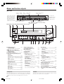
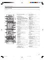

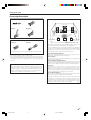

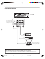

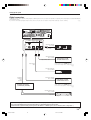
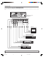
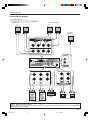
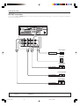
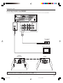
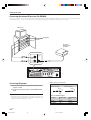
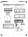
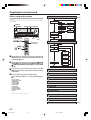
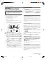

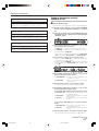
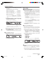
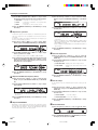
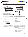
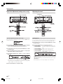
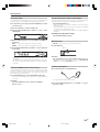

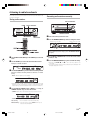
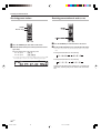


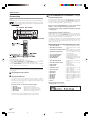
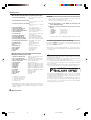

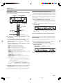
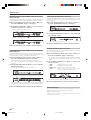
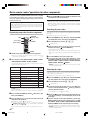

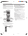


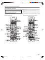


![KRF-X9090D - [::] Kenwood ASC](http://vs1.manualzilla.com/store/data/006742857_1-f5385b623f9fcf5dbe3a5d5061569373-150x150.png)