1
Owners
Manual
FOR POTABLEWATER
HEATING ONLY
NOT SUITABLE FOR
SPACEHEATING
Model
No.
153.317020
2 GaL
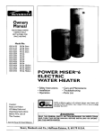
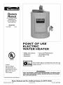
POINT
OF USE
ELECTRIC
WATER
HEATER
• Safety Instructions
• Installation
• Operation
• Care and Maintenance
• Troubleshooting
• Parts List
LISTED
GAMA certification applies to all residential electric water heaters with
capacities of 20 to 120 Gallons. Input rating of 12 Kw or lessat a voltage
no greater than 250 _L
Caution:
Read and Follow
All Safety Rules and
Operating Instructions
Before First Use of
This Product.
_WARNING
READ THE GENERAL SAFETY SECTION
BEGINNING
ON
AND THEN THIS ENTIRE MANUAL
BEFORE INSTALLING
ING THIS WATER HEATER.
INSIDE COVER
OR OPERAT-
Savethis Manual for Future Reference.
Sears, Roebuck
Printed in the U.S.A. 1203
and Co., Hoffman
www.sears.com
Estates,
IL 60179
U.S.A.
Part No. 184734-000
Safety
AWARNING
J
HAZARD OF ELECTRICAL SHOCK! Before removing
any access panels or servicing the water heater, make J
sure the electrical supply to the water heater is turned
"OFF". Failure to do this could result in DEATH, SERIOUS BOD LY NJURY,OR PROPERTY DAMAGE.
Precautions
AWARNING
J
Improper installation, adjustment, alteration, service or
maintenance can cause DEATH, SERIOUS BODILY
INJURY,OR PROPERTY DAMAGE. Refer to this manual J
for assistanceor consult your local Sears Service Center
for further information.
AWARNING
HOTTER
WATER CAN SCALD: Water heaters are
intended to produce hot water. Water heated to a tem)erature which will satisfy space heating, clothes washing,
dish washing, and other sanitizing needs can scald and
_ermanently injure you upon contact. Some people are
more likely to be permanently injured by hot water than
others. These include the elderly, children, the infirm, or
physically/mentally
handicapped.
If anyone using hot
water in your home fits into one of these groups or if
there is a local code or state law requiring a certain tem)erature water at the hot water tap, then you must take
special precautions. In addition to using the lowest possible temperature
setting that satisfies your hot water
needs, a means such as a mixing valve, shall be used at
the hot water taps used by these people or at the water
heater. Mixing valves are available at plumbing supply or
hardware stores. Follow manufacturers instructions for
installation of the valves. Before changing the factory setting on the thermostat,
read the "Temperature
Regulation" section in this manual.
AWARNING
At thetime of manufacturethis water heaterwasprovidedwith
a combinationtemperature-pressures
relief valvecertifiedbya
nationally recognizedtestinglaboratory that maintainsperiodic
inspectionof productionof listedequipmentor materials,as
meeting the requirements for ReliefValvesand Automatic Gas
ShutoffDevicesfor Hot Water SupplySystems,and the current
editionof ANSI Z21.22, CSA 4.4 andthe coderequirementsof
ASME. If replaced, the valvemust meet the requirements of
localcodes,but not less than a combinationtemperature and
_ressurerelief valvecertifiedas meeting the requirements for
ReliefValvesand AutomaticGasShutoffDevicesfor Hot Water
SupplySystems,ANSI Z21.22 0 CSA 4.4 by a nationally recognized testinglaboratorythat maintains periodicinspectionof
_roductionoflistedequipmentor materials.
The valvemust be marked with a maximum set pressurenot
to exceed the marked hydrostaticworking pressureof the
water heater (150 Ibs./sq.in.) and a dischargecapacitynot
lessthan the water heater input rate as shownon the model
rating plate. (Electric heaters, watts dividedby 1000x 3412
equalBTU/Hr. rate.)
Yourlocaljurisdictional
authority,while mandating the useof a
temperature-pressure
relief valvecomplyingwith ANSI Z21.22,
CSA 4.4 and ASME,may require a valvemodeldifferentfrom
the onefurnishedwiththe waterheater
Compliancewith suchlocalrequirements must be satisfiedby
the installeror end user of the water heaterwith a locallyprescribedtemperature-pressurerelief valveinstalledin the designated openingin the water heater in placeof the factory furnishedvalve.
Forsafeoperationofthe water heater,the relief valvemust not
be removedfrom it'sdesignated
openingor plugged.
The temperature-pressure
relief valvemust be installeddirectly
intothe f'_ingof the water heaterdesignated
for the reliefvalve.
Positionthe valvedownwardandprovidetubingsothat any dischargewill exit onlywithin 6 inchesabove,or at anydistance
belowthe structural floor.Be certainthat no contactis made
with any liveelectricalpart The discharge
openingmust not be
blockedor reduced in size underany circumstances.
Excessive
length,over 30 feet, or useof more than four elbowscan cause
restriction and reducethe discharge
capacityofthe valve.
No valveor other obstructionisto be placedbetween the relief
valveand the tank. Do not connecttubingdirectlyto discharge
drainunlessa 6"air gapisprovided.
To preventbodilyinjury,hazard to life,or propertydamage,the relief valvemust be allowed
to discharge
water in quantitiesshouldcircumstances
demand.If
the dischargepipeisnot connectedto a drainor othersuitable
means,thewaterflowmay causepropertydamage.
The DischargePipe:
•
Must not be smaller in size than the outlet pipe size of
the valve, or have any reducing couplings or other
restrictions.
•
Mustnot be pluggedor blocked.
•
Mustbe of material listed for hot water distribution.
•
Must be installed so as to allow complete drainage of
both the temperature-pressurerelief valve,and the dischargepipe.
•
Mustterminate at an adequatedrain.
•
Mustnot haveanyvalvebetweentbe relief valveand tank.
AWARNING
WATER HEATERS EQUIPPED
FOR ONE VOLTAGE
ONLY: This water heater is equipped for one type voltage
only. Check the rating plate near the bottom access panel
for the correct voltage. DO NOT use this water heater
with any voltage other than the one shown on the model
rating plate. Failure to use the correct voltage can cause
problems which can result in DEATH, SERIOUS BODILY
INJURY, OR PROPERTY DAMAGE. If you have any questions or doubts consult your electric company.
AWARNING
INSULATING
JACKETS: When installing an external
water heater insulation
jacket on an electric water
heater:
a. DO NOT cover the temperature-pressure
relief valve.
b. DO NOT put insulation over the access covers or any
access
areas.
c. DO NOT remove operating instructions, and safety
related
warning
labels and materials
affixed to
the water heater.
d. DO obtain new warning and instruction labels from
Sears for placement on the jacket directly over the
existing labels.
AWARNING
Do not usethis appliance if any part of it has been under
water. An electrical short or malfunction could occur.The
water heater shouldbe replaced.
A CAUTION
WATER HEATERS EVENTUALLY
LEAK: Installation of
the water heater must be accomplished in such a manner
that if the tank or any connections should leak, the flow of
water will not cause damage to the structure. When such
locations cannot be avoided, a suitable drain pan should
be installed under the water heater. Drain pans are available at your local Sears Store. Such a drain pan must be
piped to an adequate drain.
2
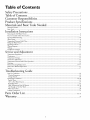
Table of Contents
Safety Precautions ....................................................................................................
.2
Table of Contents ...............................................................................................
.3
Customer Responsibilities ................................................................................
.4
Product Specifications ............................................................................................
.4
Materials and Basic Tools Needed ..................................................................
5
Materials Needed ......................................................................................................................................................................
Basic _Ibols................................................................................................................................................................................
5
5
Installation Instructions
Removing the Old Water Heater. ............................................................................................................................................
Facts to Consider About the Location .....................................................................................................................................
.6
.7
Optional Wall Mounting .....................................................................................................................................................
Water Piping ............................................................................................................................................................................
_l_mpemture-Pressure Relief Valve............................................................................................................................................
Filling the Water Heater ..........................................................................................................................................................
Optional Cord Set ..................................................................................................................................................................
Wiring Diagrams ..................................................................................................................................................................
Wiring ....................................................................................................................................................................................
Installation Checklist ..............................................................................................................................................................
.7, 8
.8
.9
10
10
10
11
12
Service and Adjustment
*l_mpemture Regulation ..........................................................................................................................................................
Thermostats ............................................................................................................................................................................
*l_mpemture Settings ..............................................................................................................................................................
Thermostat Adjustment ..........................................................................................................................................................
*l_mpePature-Pressure Relief Valve Operation ..........................................................................................................................
Draining .................................................................................................................................................................................
Element Cleaning/Replacement ........................................................................................................................................
Drain Valve Washer Replacement ...........................................................................................................................................
Service ....................................................................................................................................................................................
Troubleshooting
13
13
13
13
14
14
15-17
17
17
Guide
Start Up Conditions ...............................................................................................................................................................
Tbennal Expansion ...............................................................................................................................................................
Strange Sounds .....................................................................................................................................................................
Operational Conditions ....................................................................................................................................................
Smelly Water .........................................................................................................................................................................
"Air" in Hot Water Faucets ..................................................................................................................................................
Rumbling Noise ....................................................................................................................................................................
High "Ihnperature Shut Of}'System ...............................................................................................................................
Not Enough or No Hot _T&ter.............................................................................................................................................
Water Is _IboHot .................................................................................................................................................................
Leakage Checkpoints .............................................................................................................................................................
18
18
18
19, 20
19
19
19
19, 20
20
20
21
Parts Order List ...........................................................................................................................................
22, 23
Warranty .............................................................................................................
24
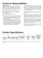
Customer
Thank
Responsibilities
The installation
must conform with the instructions
in this
manual; electric company rules; and Local Codes, or in the
absence of Local Codes, with the current edition of the NEC,
National Electrical Code NFPA 70. This publication is available
from your local government or public library or electric company or by writing Underwriters Laboratories Inc., 333 Pfingsten
Road, Northbrook, 1L 60062.
You
for purchasing
a Sears water heater.
Properly installed and maintained,
it should give you years of
trouble free service. If you should decide that you want the new
water heater professionally
installed by Sears call the local
Service Center or any Sears store. They will arrange for prompt,
quality installation by Sears authorized contractors.
Abbreviations
Found
In This Instruction
Manual
U.L. - Underwriters
Laboratories
Inc., 333 Pfingsten
Northbrook,
IL 60062
NEC - National Electrical Code
ANSI - American National Standards Institute
• If after reading this manual you have any questions or do not
understand
any portion
of the instructions,
call Sears
Service Center.
Rd.,
Carefully plan the place where you are going to put the water
heater. Correct electrical wiring and connections
are very
important in preventing death from possible electrical shock
and fires. Examine the location to ensure the water heater complies with the "Facts to Consider About the Location" section.
• Read the "Safety Precautions" section, page 2 of this manual
first and then the entire manual carefully, lfyou don't follow
the safety rules, the water heater will not operate properly. It
could cause DEKFH, SERIOUS BODILY INJURY AND/OR
PROPERTY DAMAGE.
This manual contains instructions for the installation, operation, and maintenance of this electric water heater. It also contains warnings throughout the manual that you must read and
be aware ot: All warnings and all instructions are essential to
the proper operation of the water heater and your safety. Since
we cannot put everything on the first few pages, READ THIS
ENTIRE
MANUAL
BEFORE
ATTEMPTING
TO
INSTALL OR OPERATE THE WXFER HEATER.
Product
MODEL
NUMBER
153.317020
For California installation this water heater must be braced,
anchored, or strapped to avoid falling or moving during an
earthquake. See instructions for correct installation procedures.
Instructions
may be obtained from your local dealer, wholesaler, public utilities or California Office of the State Architect,
400 P Street, Sacramento, CA 95814.
Massachusetts Code requires this water heater to be installed
in accordance with Massachusetts 248-CMR 2.00: State
Plumbing Code and 248-CMR 5.00.
Specifications
TANK
CAPACITY DIMENSIONS
IN GALLONS DIAMETER
2
*Wiring size based on standard
trical code.
10"
IN INCHES
HEIGHT
MINIMUM
WIRE SIZE*
@ 90°E RISE
ELEMENT
WATTAGE
120 Volt
(GAUGE)
MAXIMUM FUSE
OR CIRCUIT
BREAKER
SIZE (AMPS)
7
1440
12
20
RECOVERY RATE
GALS. PER HOUR
12¾"
60°C copper wire. If distance
from fuse box to water heater is more than 90 feet, refer to your local elec-
4
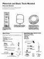
Materials
Materials
and Basic Tools Needed
Needed
"Ib simplify the installation Sears has available the installation
parts shown below. You may or may not need all of these materials, depending on your type of installation.
EXPANSION TANKS FOR THERMAL
EXPANSION
CONDITIONS
AVAILABLE
IN 2 GALLON CAPACITY THROUGH
LOCAL SEARS SERVICE CENTERS
WATER HEATER INSTALLA.
TION KIT WITH FLEXIBLE
CONNECTORS
FOR 3/4" OR
1/2" THREADED OR COPPER
PLUMBING
Basic Tools
DRAIN PANS AVAILABLE IN 20"
DIAMETER FOR WATER HEATERS
HAVING A DIAMETER 18" OR LESS,
24" DIAMETER FOR WATER
HEATERS HAVING A DIAMETER 22"
OR LESS AND AVAILABLE IN 28"
DIAMETER FOR WATER HEATERS
HAVING A DIAMETER 26" OR LESS
ADDITIONAL
TOOLS
SWEAT
SOLDERING
You may or may not need all of these tools, depending on your
type of installation. These tools can be purchased at your local
Sears store.
Pipe Wrench (2) 14"
Screwdriver
6 Foot Tape or Folding Rule
Garden Hose
Drill
Pipe Dope or Teflon Tape
NEEDED
WHEN
Tubing Cutters or Hacksaw
Propane Torch
Soft Solder
Solder Flux
Emery Cloth
Wire Brushes
HACKSAW
6 FOOT TAPE
GARDEN
HOSE
3/4" WIRE BRUSH
SLOT-HEAD
SCREWDRIVER
PIPE
1/2" WIRE BRUSH
WRENCH
PHILLIPS
SCREWDRIVER
PROPANE
TORCH
ROLL OF LEAD FREE
SOFT SOLDER
PIPE DOPE (SQUEEZE
TUBE)
_//
roll of teflon tape
(Use only on water connections)
DRILL
ROLL OF EMERY
CLOTH
SOLDER
FLUX
TUBING
CUTTER
Installation
Instructions
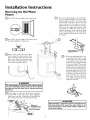
Removing the Old Water
Heater
Q'Ihrn
('_
"OFF" electrical supply to the water heater.
Qa.
If you have copper piping to the water heater,
the two copper water pipes can be cut with a
hacksaw approximately 4" away from where
they connect to the water heater. This will
avoid cutting off the pipes too short.
Additional cuts can be made later if necessary.
Disconnect the temperature-pressure
relief
valve drain line. When the water heater is
drained, disconnect the hose from the drain
valve. Close the drain valve. The water heater
is now completely disconnected and ready to
be removed.
"lhrn ......
OFF the water supply to the water heater at
the water shutoffvalve or water meter.
Attach a hose to the water heater drain
valve and put the other end in a floor
drain or outdoors. Open the water heater
drain valve. Open a nearby hot water
faucet which will relieve pressure in the
water heater and speed draining.
Q
®
b. If you have galvanized pipe to the
water heater, loosen the two galvanized pipes with a pipe wrench
at the union in each line. Also
disconnect the piping remaining
to the water heater. These pieces
should be saved since they may be
needed when reconnecting the
new water heater. Disconnect the
temperature-pressure relief valve
drain line. When the water heater
is drained, disconnect the hose
from the drain valve. Close the
drain valve. The water heater is
now completely disconnected and
ready to be removed.
_,WARNING
]
The water passingout of the drain valve may be extreme- ]
ly hot. To avoid being scalded, make sure all connectionsI
are tight and that the water flow is directed away from
any person.
Q
Gheck againto make sure the electrical supply is
turned OFF to the water heater. Then unplug the
water heater (cord set) or disconnect the electrical supply connection from the water heater junction box.
CAUTION
_
CLAMP
_
___
I
Mineral buildupor sediment may have accumulated in the
old water heater. This causes the water heater to be I
much heavier than normal and this residue, if spilledout,
could causestaining.
ACCESS OPENING
HEATER
WIRING
6
Installation
Instructions
(cont'd)
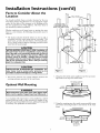
Facts to Consider About the
Location
WALL
You should carefully choose an indoor location for the new
water heater, because the placement is a very important consideration for the safety of the occupants in the building and for
the most economical use of the appliance. This water heater is
not intended for outdoor installation.
PLYWOOD(MIN. ½"
THICKNESS)LAPINGAT
LEASTTWO WALL STUDS
MIN. 2" x 4" WHICH LAPSAT
LEASTTWO WALL STUDS
8_¼" x 3"
WOOD SCREWS
Whether
replacing an old water heater or putting the water
heater in a new location, the following critical points must he
observed.
•
/x
The location selected should be indoors as close to and as
centralized with the water piping system as possible. This
water heater, as well as all water heaters, will eventually leak.
Do not install without adequate drainage provisions where
water flow will cause damage.
_i, CAUTION
WATER HEATERS EVENTUALLY
LEAK: Installation of
the water heater must be accomplished in such a manner
that if the tank or any connections should leak, the flow of
water will not cause damage to the structure. When such
locations cannot be avoided, a suitable drain pan should
be installed under the water heater. Drain pans are available at your local Sears stores. Such a drain pan must be
piped to an adequate drain.
WATER HEATER
MOUNTING BRACKETS
_, CAUTION
INSTALLATION
IN RESIDENTIAL
GARAGES:
The I
water heater must be located and/or protected so it is
[Figure,]
IFigu.e21
not subject to phys ca damage by a mov ng veh c e.
•
The location selection must provide adequate clearances
servicing and proper operation of the water heater.
1. Using two sheet metal screws supplied, secure the top mounting bracket to the top of the water heater.
for
SECURING
Optional
SCREWS
_ (SUPPLIED!
Wall Mounting
UPPER
BRACKET
! ....
_L
•
IIW
,_ #8-18x_/_
I
C
_,WARNING
J
Wall construction at the point of the water heater instalat on must be capab e of support ng at east 200 pounds.
As an example: if the water heater is to be installed on a wall of
gypsum board (dry wall) or other material not capable of supporting the water heater filled with water, additional bracing will
be necessary. "I_vopossibilities are shown below.
!¢
i!
-J
o
11
1
3
2. Using the remaining two sheet metal screws provided, secure
the bottom mounting
bracket to the bottom of the water
heater.
LOWER
BRACKET
SECURING
SCREWS
(SUPPLIED)
#8-18 x %'_
7
Installation
Instructions
Optional Wall Mounting (cont'd)
3. Determine the location on the wall, and then the height
above the floor which the wall securing bracket will be
placed. Using adequate screws, or nuts and bolts (not supplied), fasten the wall securing bracket to the wall.
"_"-"-I
SECURING
SCREW TO
WALL M[N.
12 x _Z,_'
"_I
(NOT SUPPLIED)
(cont'd)
If a water heater is installed in a closed water supply system;
such as one having a back-flow preventer, check valve, water
meter with a check valve, etc.., in the cold water supply; means
must be provided to control thermal expansion. Contact the
local utility or SearsService Center on how to control this situation.
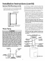
The illustration shows the attachment of the water piping to the water
heater. The water heater is equipped with _" water connections.
• Look at the top of the water heater. The hot water outlet is
marked hot. Put two or three turns of teflon tape around the
threaded end of the compression coupling and around the _"
threads of the 5_"x ½"reducer bushing. Put two or three turns of
teflon
..... tape around both ends, of a Vd' threaded_
,, nip le (not. supplied in the mstallauon kit). Attach the Z threa_ed topple to
the _" x }_"reducer bushing and screw into the hot water outlet
of the water heater. Using flexible connectors, connect the hot
water pipe to the hot water outlet of the water heater.
NOTE: If using copper tubing, solder tubing to an
adapter before attaching the adapter to the water connections. Do not solder the water supply lines directly to the
connections of the water heater. It will harm the fittings
on the water heater.
_
Water
SECURING
SCREWTO
WALL MIN.
12x%"
(NOT SUPPLIED)
Piping
*A WARNING
HOTTER WATER CAN SCALD: Water heaters are intended to produce hot water. Water heated to a temperature
vhich will satisfy space heating, clothes washing, dish washing, and other sanitizing needs can scald and permanently
injure you upon contact. Some people are more likely to be
_ermanently
injured by hot water than others. These
include the elderly, children, the infirm, or physically/men.
tally handicapped. If anyone using hot water in your home
fits into one of these groups or if there is a local code or
state law requiring a certain temperature water at the hot
water tap, then you must take special precautions. In addition to using the lowest possible temperature setting that
satisfies your hot water needs, a means such as a mixing
valve, shall be used at the hot water taps used by these people or at the water heater. Mixing valves are available at
plumbing supply or hardware stores. Follow manufacturers
instructions for installation of the valves. Before changing
the factory
setting on the thermostat,
read the
"Temperature Regulation" section in this manual.
HOT WATER A
OUTLET
T
Look at the top of the water heater. The cold water inlet is
marked cold. Put two or three turns of teflon tape around the
threaded end of the compression coupling and around the _"
threads of the 5_"x ½"reducer bushing. Put two or three turns of
teflon
..... tape around both ends, of a Vd' threaded_
,, nip_jple(not. supplied m the mstallauon kzt). Attach the Z threaded topple to
the _" x Vd'reducer bushing and screw into the cold water inlet
of the water heater. Using flexible connectors, connect the hot
water pipe to the hot water outlet of tile water heater.
NOTE: Your water heater is insulated to minimize heat
loss from the tank. Further reduction in heat loss can be
accomplished by insulating the hot water lines from the
water heater.
Installation
COMPLETED
Installation
Kit
SHUT-OFF
1/2" x314" REDUCER_
_
BUSHING
1/2
THREADED_
_,_
NIPPLE (not supplied _ ..--_Y_
with installation kit) /_--_-_-J_-_
COLD WATER
-----¢.1
TEMPERED_
WATER OUTL
_¢TO COLD WATER
INLET ON
WATER HEATER
*MIXING VALVE
WATER OUTLET
ON WATER HEATER
using
1/2" x3/4"
REDUCER
BUSHING
_1/2
......
THREADED
_
_
NIPPLE (not supplied
"\with
installation kit)
Installation
Instructions
(cont'd)
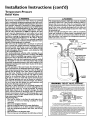
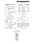
Temperature-Pressure
Relief Valve
&WARNING
&WARNING
At the time of manufacture this water heater was provided
with a combination temperature-pressures relief valve certified by a nationally recognized testing laboratory that maintains periodic inspection of production of listed equipment
or materials, as meeting the requirements for Relief Valves
and Automatic Gas Shutoff Devices for Hot Water Supply
Systems, and the current edition of ANSI Z21.22 • CSA 4.4
and the code requirements of ASME. If replaced, the valve
must meet the requirements
of local codes, but not less
than a combination temperature and pressure relief valve
certified as meeting the requirements for Relief Valves and
Automatic Gas Shutoff Devices for Hot Water Supply
Systems, ANSI Z21.22, CSA 4.4 by a nationally recognized
testing laboratory that maintains periodic inspection of production of listed equipment or materials.
The valve must be marked with a maximum set pressure
not to exceed the marked hydrostatic working pressure of
the water heater (150 Ibs./sq. in.) and a discharge capacity
not less than the water heater input rate as shown on the
model rating plate. (Electric heaters, watts divided by 1000
x 3412 equal BTU/Hr. rate.)
Your local jurisdictional authority, while mandating the use
of a temperature-pressure relief valve complying with ANSI
Z21.22 0 CSA 4.4 and ASME, may require a valve model different from the one furnished with the water heater.
Compliance with such local requirements must be satisfied
by the installer or end user of the water heater with a locally
)rescribed temperature-pressure relief valve installed in the
designated opening in the water heater in place of the factory furnished valve.
For safe operation of the water heater, the relief valve must
not be removed from it's designated opening or plugged.
The temperature-pressure
relief valve must be installed
directly into the fitting of the water heater designated for
the relief valve. Position the valve downward and provide
tubing so that any discharge will exit only within 6 inches
above, or at any distance below the structural floor. Be certain that no contact is made with any live electrical part.
The discharge opening must not be blocked or reduced in
size under any circumstances. Excessive length, over 30 feet,
or use of more than four elbows can cause restriction and
reduce the discharge capacity of the valve.
No valve or other obstruction is to be placed between the
relief valve and the tank. Do not connect tubing directly to
discharge drain unless a 6" air gap is provided. To prevent
bodily injury, hazard to life, or property damage, the relief
valve must be allowed to discharge water in quantities
should circumstances demand. If the discharge pipe is not
connected to a drain or other suitable means, the water flow
may cause property damage.
The Discharge Pipe:
Must not be smaller in size than the outlet pipe size of
the valve, or have any reducing
couplings or other
restriction.
Must not be plugged or blocked.
Must be of material listed for hot water distribution.
Must be installed so as to allow complete drainage of
both the temperature-pressure relief valve, and the discharge pipe.
Must terminate at an adequate drain.
Must not have any valve between the relief valve and tank.
The temperature-pressure
relief valve must be manually
operated at least once a year. Caution should be taken to
ensure that (I) no one is in front of or around the outlet
of the temperature-pressure
relief valve discharge line,
and (2) the water manually discharged will not cause any
bodily injury or property damage because the water may
be extremely hot.
If after manually operating the valve, it fails to completely
reset and continues to release water, immediately, close
the cold water inlet to the water heater, follow the draining instructions, and replace the temperature-pressure
relief valve with a new one.
VALVE
._(
COLD
HOT
LIRE-PRESSURE
RELIEF VALVE
DISCHARGE
PIPE
(Do not cap or
plug. Provide
a 6"
air gap between
pipe and drain.)
.FLOOR
DRAIN
WARNING
"RELIEF
VALVE
OPENING"
11dewatel beater is prowbed w_ha ¢0mb[natbnT_l_lp6emtule_Pressure
Relbf Valvelisiod as coEy_01y[nlg
w_/
the sbe'dafdfor ReliefValves a'tl A_lomatb Gas Shddl Oevicestor HotWaterS®#y System& AN$ Z2122
aid tie coderedei_le_Ls of ASME
Your10caJ
iu_odictmn_Jauthe(_y,while nland_ng tie use of a Temp_ature-Pmssure ReliefValvecomplying
_ith AN8Z2122 and ASME,may requirea valvemodeld_ferentflora theone _rnisbed withthe watelheater
Com_ian_ withSUChIoca_requile_'_r_smusthe satisfiedby the ins[aHerel end user of tie watel beaterwith
a locally prescribed TemberaIure,Piessure Relief VaJveinstaJlodin t_ desighated ®ening in the water
heater
• Ifa shoIt shank (less lhan 2") temperature*pressure relief ValVeis to be inslalled
(as shown), a nipple and co®ling must be Used
• If a long shank (2" or brger) is to be installed, de not use the nipple and co®ling
'I nsta_lTer®eralure_Pressule protec_veeq_pment redeirodby IocaJcodes, bL4notless thai a combina*
lien Temper atule.Presst_reRelief V_lve certified as meeting Ibe redeilements for Relief Valves and
AulomaticGas $betdf Deviceslor Hot-WalerSubely Systems,ANS Z2122 by _ nadena_lyrecognized test_
_g laboratory tbe_msJntainsperiodb in_on
Of production of listed edeipment or matelbJs The valve
must be ortentod,j3iowbedw_thtub_rg,el otbervaseinstsJlodso _at d_scharge•
caq ex_•only _thin_6 inches
above, or at any dlstaqcebelowthestfuctt_ra_f_oor,
aod c_{_ot cont_ any I_veelectnca_part¸
Fol safe ®elation of _ waterbealel, _e R_l_efVahtemust not be removed el _YULqge_J
See manual heading * 'Tern betature*PressuleRelod V_]ve'r for ins®laden and maintenanceof Relief
Valve, dmcbergepipe ard other safely preeautJ®s
9
Installation
Filling the Water
Instructions
Heater
(cont'd)
Wiring
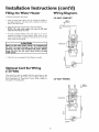
"Ib fill the water heater with water:
120 VOLT
Diagrams
CORD
• Close the water heater drain valve by turning the handle to
the right (clockwise). The drain valve is located on the lower
front of the water heater.
SET
GREEN
• Open the cold water supply valve to the water heater.
NOTE: The cold water supply valve must be left open
when the water heater is in use.
• _lb insure complete filling of the tank, allow air to exit by
opening the nearest hot water faucet. Allow water to run
until a constant flow is obtained. This will let air out of the
water heater and the piping.
A CAUTION
J
Never use this water heater unless it is completely full J
of water. To prevent damage to the tank and heating
element, the tank must be filled with water. Water I
must flow from the hot water faucet before turning
ON ' power.
• Check all new water piping for leaks. Repair as needed.
Optional
Cord Set Wiring
(120Volt)
There may be a cord set supplied with the water heater at the
time of manufacture. If not one can be ordered through the
Parts Department, see "Repair Parts" section. Refer to figures on
this page for wiring diagrams.
120 VOLT WIRING
Lu
THERMOSTAT
=
10
GREEN
.Jl
GROONO
Installation
Instructions
(cont'd)
Wiring
CAUTION
B. Rigid metal conduit, intermediate metal conduit, or electrical metallic tubing may be used for the grounding
means if conduit ortubing
is terminated in fittings
approved for grounding.
J
Never use this water heater unless it is completely full J
of water. To prevent damage to the tank and heating
element, the tank must be filled with water. Water I
must flow from the hot water faucet before turning
ON ' power.
C. Flexible metal conduit or flexible metallic tubing shall be
permitted for grounding if all the following conditions
are met:
1.
You must provide all wiring of the proper size outside of the
water heater. You must obey local codes and electric company
requirements when you install this wiring.
The length in any ground return path does not exceed
6 feet.
2. The circuit conductors contained therein are protected by overcurrent devices rated at 20 amperes or less.
If you are not familiar with electric codes and practices, or if you
have any doubt, even the slightest doubt, in your ability to connect the wiring to this water heater, obtain the service of a competent electrician. Contact your Sears salesperson to arrange for
a professional electrician.
3. The conduit or tubing is terminated
in fittings
approved for grounding. For complete grounding
details and all allowable exceptions, refer to the current edition of the National Electrical Code, NFPA
70.
4.
_,WARNING
WATER HEATERS EQUIPPED FOR ONE VOLTAGE
ONLY: This water heater is equipped for one type voltage only. Check the rating plate near the bottom
access panel for the correct voltage. DO NOT use this
water heater with any voltage other than the one
shown on the model rating plate. Failure to use the
correct voltage can cause problems which can result in
DEATH, SERIOUS BODILY INJURY, OR PROPERTY
DAMAGE. If you have any questions or doubts consult
your electric company.
A standard _" conduit opening has been made in the
water heater junction box for the conduit connection.
5. Use wire nuts and connect the power supply wiring to
the wires inside the water heater's junction box.
6. The water heater must be electrically "grounded" by
the installer. A green ground screw has been provided
on the water heater's junction box. Connect ground
wire to this location.
7.
Replace the wiring junction
provided.
cover using the screw
GREEN GROUND SCREW
CAUTION
If wiring from your fuse box or circuit breaker box
was aluminum for your old water heater, replace
it with copper wire. If you wish to reuse the existing aluminum wire, have the connection at the
water heater made by a competent electrician.
Contact your Sears salesperson to arrange for a
professional electrician.
TO SERVICE
PANEL
GROUND
WIRE
WIRE NUT
CONNECTIONS
ACCESS Ot_Eb,!ING
1. Provide a way to easily shut off the electric power when
working on the water heater. This could be with a circuit
breaker or fuse block in the entrance box or a separate disconnect switch.
HEATER
WIRING
2. Install and connect a circuit directly from the main fuse or
circuit breaker box. This circuit must be the right size and
have its own fuse or circuit breaker. Refer to the chart in the
"Product Specifications" section for the correct size wire and
fuse or circuit breaker.
3. If metal conduit is used for the grounding conductor:
A. The grounding electrode conductor shall be of copper,
aluminum, or copperclad aluminum. The material shall
be of one continuous length without a splice or joint.
11
Installation
Installation
Instructions
(cont'd)
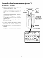
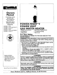
Checklist
ls the fuse or circuit breaker size correct as shown in the
chart in the "Product Specifications" section?
SHUT-OFF
TEMPERATURE-PRESSURE
RELIEF VALVE
Are the wires from the circuit breaker or fuse service to the
water heaters' juncnon"
" box on,,the correct wire size m,.,(_uge_
as shown in the chart in the Product Specifications section?
HOT WATER
COLD WATER
ls the new temperature-pressure
relief valve properly
installed, and piped to an adequate drain? See "'l_mperaturePressure Relief Valve" section.
DISCHARGE PIPE
(Do not cap or plug.
Provide a 6" air gap
between the end of the
pipe and drain.)
ls the water heater completely filled with water? See "Filling
the Water Heater" instructions
in the "Installation
Instructions
section.
•
Will a water leak damage anything? See "Facts to Consider
About the Location" section.
•
Are the cold and hot water lines connected to the water
heater correctly? See "Water Piping" instructions in the
"Installation Instructions" section.
Is there adequate clearance for maintenance
water heater?
DRAIN VALVE
around the
Do you need to call your electric company to check your
wiring?
FLOOR
MODEL
12
RATING
PLATE
DRAIN
Service
and Adjustment
Temperature
Regulation
Temperature
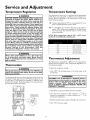
The thermostat is factory set at a position which approximates
120°F (Hot) and is adjustable if a different water temperature is
desired. Read all warnings in this manual and on the water
heater before proceeding.
&WARNING
HOTTER
WATER CAN SCALD: Water heaters are
intended to produce hot water. Water
heated to a
temperature
which will satisfy clothes washing, dish
washing, and other sanitizing needs can scald and permanently injure you upon contact. Some people are
more likely to be permanently
injured by hot water
than others. These include the elderly, children, the
infirm, or physically/mentally
handicapped.
If anyone
using hot water in your home fits into one of these
groups or if there is a local code or state law requiring
a certain temperature
water at the hot water tap,
then you must take special precautions. In addition to
using the lowest possible temperature
setting that satisfies your hot water needs, some type of tempering
device, such as a mixing valve, should be used at the
hot water taps used by these people or at the water
heater. Mixing valves are available at plumbing supply
or hardware stores. Follow manufacturers
instructions
for installation
of the valves, Before changing the
factory
setting
of the
thermostat,
read
the
"Temperature
Regulation" section in this manual.
LO- Setting, approximately 95°F, is recommended
tions or extended periods of no hot water.
NOTE:
mended
Water temperature
by most dishwasher
range of 120°--140°F
manufacturers.
t60°F
About 1/2 seconds
150°F
About I - 1/2 seconds
140°F
Lessthan S seconds
130°F
About 30 seconds
120°F
Hore than 5 minutes
Thermostat
recom-
Adjustment
The thermostat is adjustable if a different water temperature is
desired. Read all warnings in the "'f_mperature Regulation" section before proceeding.
Thermostats
"lb adjust the temperature setting:
_,WARNING
J
This specialthermostat with ECO (Part No. 9002394) can
only be used with this water heater. Do not use any other I
thermostat with ECO.
I
1. "_(hrn"OFF" the electrical power to the water heater at the
junction box.
AWARNING
The thermostat of this water heater has been factory set at the
mid position which approximates 120°F (Hot) to reduce the risk
of scald injury. The thermostat is adjustable if a different water
temperature is desired. Read all warnings in this manual and on
the water heater before proceeding.
HAZARD
OF ELECTRICAL
SHOCK!
Before
removing any access panels or servicing the water
heater, make sure the electrical supply to the water
heater is turned
"OFF".
Failure to do this could
result in DEATH,
SERIOUS
BODILY
INJURY, OR
PROPERTY
DAMAGE.
3
÷_®
for vaca-
HI- ls a setting for the maximum hot water usage approximately 140°F, which can be supplied by the water heater.
The temperature dial should be kept at a lower setting
whenever possible.
_WARNING
J
Never allow small children to use a hot water tap, J
or to draw their own bath water. Never leave a J
child or handicapped person unattended in a bathtub or shower.
I
Settings
2. _ihke off the access panel and fold away the insulation.
3. Turn the water temperature dial clockwise (f"--"N)
increase the temperature, or counter clockwise (4"-"h)
decrease the temperature.
APPROXIMATE
TEMPERATURES
_
4
to
to
4. Fold the insulation back in place and replace the access panel.
7©
5. "ihrn "ON" the power supply.
©l
©
4
AD USTABLE
THERMOSTAT
13
Service
and Adjustment
Temperature-Pressure
Valve Operation
(cont'd)
Relief
The temperature-pressure
relief valve must
ually operated at least once a year.
TEM PERATURE-PRESSU
Draining
The water heater should be drained if being shut down during
freezing temperatures. Also periodic draining and cleaning of
sediment from the tank may be necessary.
be man-
• Before beginning turn "OFF" the electric power supply to the
water heater.
RE
ELIEF VALVE
11
!1
DISCHARGE
P,PE
AWARNING
J
HAZARD OF ELECTRICAL SHOCK! Before removing
any access panels or servicing the water heater, make J
sure the electrical supply to the water heater is turned
"OFF". Failure to do this could result in DEATH, SERIOUS BOD LY NJURY,OR PROPERTY DAMAGE.
• CLOSE the cold water inlet valve to the water heater.
• OPEN a nearby hot water faucet and leave open to allow for
draining.
AWARNING
The temperature-pressure relief valve must be manually
operated at least once a year. Caution shouldbe taken to
ensure that (I) no one is in front of or around the outlet
of the temperature-pressure relief valve discharge line,
and (2) the water manually dischargedwill not causeany
property damage or bodily injury. The water may be
extremely hot.
If after manually operating the valve, it fails to completely
reset and continues to release water, immediately close
the cold water inlet to the water heater,follow the draining instructions, and replace the temperature-pressure
relief valvewith a new one.
• Connect a hose to the drain valve and terminate to an adequate
drain or outdoors.
• OPEN the water heater drain valve to allow for tank draining.
NOTE: If the water heater is going to be shut down and
drained for an extended period, the drain valve should be
left open with hose connected allowing water to terminate
to an adequate drain.
• Close the drain valve.
• Follow "Filling the Water Heater"
"Installation Instructions" section.
Failure to install and maintain a new properly listed temperaturepressure relief valve will release the manufacturer from any claim
which might result from excessivetemperature or pressure.
instructions
in the
• "Ihrn "ON" power to the water heater.
A CAUTION
J
Never use this water heater unless it is completely full J
of water. To prevent damage to the tank and heating
element, the tank must be filled with water. Water I
must flow from the hot water faucet before turning
ON ' power.
AWARNING
If the temperature-pressure relief valve on the appliance
weepsor dischargesperiodically,this may be due to thermal expansion. Your water heater may have a check
valve installed in the water line or a water meter with a
check valve. Consult your local Sears Service Center for
further information. Do not plug the temperature-pressure relief valve.
14
Service
and Adjustment
(cont'd)
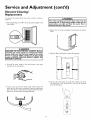
Element Cleaning/
Replacement
"Ib remove the element from your tank in order to clean or
replace it:
_,WARNING
J
The water passing out of the drain valve may be
extremely hot. To avoid being scalded, make sure all J
connections are tight and that the water flow is J
directed away from any person.
J
1. Before beginning turn "OFF" the electric power supply to the
water heater.
I
4. Remove the two screws securing the access panel, and remove
panel.
AWARNING
HAZARD
OF ELECTRICAL
SHOCK!
Before
removing
any access panels or servicing the water
heater, make sure the electrical supply to the water
heater is turned
"OFF".
Failure to do this could
result
in DEATH,
SERIOUS
BODILY
INJURY, OR
PROPERTY
DAMAGE.
5. Open the flap of insulation to expose the opening.
2. Turn off"the water supply to the water heater at the water
shutoff'valve or water meter.
6. Lift out the tab a_sshown to unclip the terminal cover from
the thermostat. The terminal cover can now be removed
from the thermostat.
3. Attach a hose to the water heater drain valve and put the
other end in a floor drain or outdoors. Open the water heater
drain valve. Open a nearby hot water faucet which will relieve
pressure in the water heater and speed draining.
15
Service
and Adjustment
(cont'd)
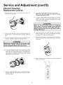
Element Cleaning/
Replacement
(cont'd)
7. Disconnect the two wires on the element and unscrew the
old element from the tank.
12. Open the cold water supply valve to the water heater.
NOTE: The cold water supply valve must be left open
when the water heater is in use.
13. "Ib insure complete filling of the tank, allow air to exit by
opening the nearest hot water faucet. Allow water to run
until a constant flow is obtained. This will let air out of the
water heater and the piping.
A CAUTION
J
Never use this water heater unless it is completely J
full of water. To prevent damage to the tank and J
heating element, the tank must be filled with water. J
Water must flow from the hot water faucet before
turn ng ' ON ' power.
14. Check element for water leaks. If leakage occurs, tighten
element or repeat steps 2 and 3, remove element and reposition gasket. Then repeat steps 10 through 14.
8. Clean the area around the element opening. Remove any
sediment from or around the element opening, inside the
tank.
15. Reconnect the two wires to the element and then check to
make sure the thermostat remains firmly against the surface
of the tank.
9. If you are cleaning the element you have removed, do so by
scraping or soaking in vinegar or a de-liming solution.
AWARNING
I
Replacement elements must (I) be the same volt-I
age and (2) no greater wattage than listed on the
mode rat ng p ate affixed to the water heater.
£
10. A new gasket should be used in all cases to prevent a possible
water leak. (See Element Gasket in the "Parts Order List"
Chart). Place the new element gasket on the thread side of
the cleaned or new element and screw into tank, securing
tightly using an element wrench.
16. Replace terminal cover on thermostat and fold insulation
back over the element.
11. Close the water heater drain valve by turning the handle to
the right (clockwise). The drain valve is on the lower front
of the water heater.
16
Service
and Adjustment
(cont'd)
Drain Valve Washer
Replacement
NOTE: For replacement, use a _d' x _3Ad'x W' thick washer
available at your nearest hardware store. For ordering a
replacement washer, refer to the "Parts Order List" section.
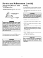
17. Fold the insulation back in place so that it completely covers
the thermostat and element.
• Before beginning turn "OFF" the electrical power supply to
the water heater.
AWARNING
HAZARD
OF ELECTRICAL
SHOCK!
Before
removing
any access panels or servicing the water
heater, make sure the electrical supply to the water
heater is turned
"OFF".
Failure to do this could
result
in DEATH,
SERIOUS
BODILY
INJURY, OR
PROPERTY
DAMAGE.
• Follow "Draining"
Adjustment" section.
instructions
in the "Service
and
18. Replace access panel.
• "Ihrning counter clockwise, remove the hex cap below the
screw handle.
19. "lhrn "ON" electric power to water heater.
• Remove the washer and put the new one in place.
• Screw the handle and cap assembly back into the drain valve
and retighten using a wrench. DO NOT OVER TIGHTEN.
• Follow "Filling the Water Heater"
"Installation Instructions" section.
instructions
in the
• Check for leaks.
• "Ihrn "ON" electric power to the water heater.
%
_
HANDLE
AND
CAP ASSEMBLY
A CAUTION
J
WASHER
Never use this water heater unless it is completely J
full of water. To prevent damage to the tank and J
heating element, the tank must be filled with water. J
Water must flow from the hot water faucet before
turn ng ' ON ' power.
Service
Before calling for repair service, read the "Start Up Conditions"
and "Operational
Conditions"
found in the Troubleshooting
Guide of this manual.
If a condition persists or you are uncertain about the operation
of the water heater, let a qualified person check it out.
Contact SEARS Repair Services
(1-800-469-4663)
17
at 1-800-4-MY-HOME
Troubleshooting
Guide
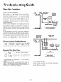
Start Up Conditions
THERMAL
EXPANSION
HOT
COLD
Water supply systems may, because of such events as high line
pressure, frequent cut-off_, the effects of water hammer among
others, have installed devices such as pressure reducing valves,
check valves, back flow preventers, etc._to control these types of
_roblems. When these devices are not equipped with an internal
y-pass, and no other measures are taken, the devices cause the
water system to be dosed. As water is heated, it expands (thermal expansion) and dosed systems do not allow for the expansion of heated water.
WATER HEATER
COLD WATER
, INLET FITTING
O)
EXPANSION
TANK
(z)
The water within the water heater tank expands as it is heated and
increases the pressure of the water system. If the relieving point of
the water heater's temperature-pressure
relief valve is reached, the
valve will relieve the excess pressure. The temperature-pressure
relief valve is not intended for the constant relief of thermal
expansion. This is an unacceptable condition and must be corrected.
PRESSUREGAUGE
Tank
FLOOR,CEILING
JOIST,ETC.
WATER HEATER
COLD WATER
INLET FITTING
MOT
Expansion
WATER
SHUTOFF
RECOMMENDED INSTALLATION
(VERTICAL MOUNTING)
It is recommended that any devices installed which could create a
closed system have a by-pass and/or the system have an expansion tank to relieve the pressure built by thermal expansion.
Thermal expansion tanks are available from Sears stores and
through the Sears Service Centers. Contact the local plumbing
inspector, water supplier and/or the Sears Service Center for
assistance in controlling these situations.
Thermal
(3)
PRESSURE
REDUCING
VALVEWITH
BY-PASS
COLD
STRAPPING
Specifications
Model
"I_tnkCapacity
Dimensions in Inches ] Pipe Fitting
Number
153.331020
In Gallons
2
Diameter [ Length [ On "lhnk
8 inches ]12_ inches] _" Male
0)
PRESSURE
REDUCING
VALVEWITH
BY-PASS
(0
INLET COLD
WATER
SHUTOFF
EXPANSION
TANK
Expansion
Expansion
_Ihnk
Capacity
Needed
Tank Sizing
Inlet*
Water
Pressure
40-80psi
Chart
(2)
Water Heater Capacity
2
2
4
2
6
2
(Gallons)
10
2
PRESSUREGAUGE
ALTERNATE RECOMMENDED
INSTALLATION
(HORIZONTAL MOUNTING)
19.9
2
*Highest recorded inlet water pressure in a 24 hour period or
regulated water pressure.
STRANGE
NOTE= Expansion tanks are pre-charged with a 40 psi air
charge. If the inlet water pressure is higher than 40 psi, the
expansion tank's air pressure must be adjusted to match that
pressure, but must not be higher than 80 psi.
SOUNDS
Possible noises due to expansion and contraction of"some metal
_arts during periods of heat-up and cool-down do not represent
armful or dangerous conditions.
18
Troubleshooting
Operational
SMELLY
Guide
Conditions
WATER
RUMBLING
In each water heater there is installed an anode rod for corrosion
protection
of the tank. Certain water conditions
will cause a
reaction between this rod and the water. The most common
complaint associated with the anode rod is one of a "rotten egg
smell". This odor is derived from hydrogen sulfide gas dissolved
in the water. The smell is the result of four factors which must
all he present for the odor to develop:
a. a concentration
of sulfate in the supply water.
b. little or no dissolved oxygen in the water.
c. a sulfate reducing bacteria within the water heater. (This
harmless bacteria is non-toxic to humans.)
d. an excess of active hydrogen in the tank. This is caused by
the corrosion protective action of the anode.
NOISE
In some water areas, scale or mineral deposits will build up on
your heating elements. This buildup will cause a rumbling noise.
Follow "Element Cleaning/Replacement" instructions to clean
and replace the elements.
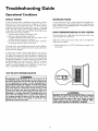
HIGH
TEMPERATURE
SHUT
OFF
SYSTEM
The water heater has a high limit shut off system with a reset
button located on the thermostat.
Follow the resetting instructions which refer to the high limit
behind the access panel.
• Before beginning, turn "OFF" electrical power supply to the
water heater.
The anode rod in a new glasslined water heater works rapidly to
protect the tank. After a period of time the anode action slows
and the odor may dissipate.
A smelly water condition (Rotten Egg Odor) in your Point of
Use water heater can, in most cases, be resolved or reduced with
the addition of sufficient amounts of chlorine to eliminate the
bacterial growth inside the tank. This can be accomplished
through the installation of a chlorine feeder to the system or the
periodic flushing of the water heater with "Chlorox" as needed.
On systems where the odor is mild and does not occur too
rapidly, a monthly flushing may be suf[]cient. In more severe
cases, a system feeder wouldbe more appropriate.
"AIR"
IN HOT
WATER
FAUCETS
_,WARNING
HYDROGEN
GAS: Hydrogen gas can be produced in a
hot water system that has not been used for a long period
of time (generally two weeks or more). Hydrogen gas is
extremely flammable and explosive. To prevent the possibility of injury under these conditions, we recommend the
hot water faucet be opened for several minutes at the
kitchen sink before any electrical appliances which are
connected to the hot water system are used (such as a
dishwasher or washing machine). If hydrogen gas is present, there will probably be an unusual sound similar to
air escaping through the pipe as the hot water faucet is
opened. There must be no smoking or open flame near
the faucet at the time it is open.
_,WARNING
I
HAZARD OF ELECTRICAL SHOCK! Before removing
any access panels or servicing the water heater, make I
sure the electrical supply to the water heater is turned
"OFF". Failure to do this could result in DEATH, SERIOUS BOD LY NJURY,OR PROPERTY DAMAGE.
19
Troubleshooting
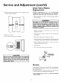
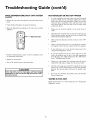
HIGH
TEMPERATURE
(cont'd)
SHUT
OFF
Guide
SYSTEM
NOT ENOUGH
• Open the flap of insulation to expose the opening.
• Reset the high limit by pushing in the red button marked
"RESET".
Make sure the electrical supply to your water heater is
"ON".
Check for loose or blown fuses in your water heater circuit.
Circuit breakers weaken with age and may not handle their
rated load and should be replaced.
I
RESET
OR NO HOT WATER
In a new installation, the water heater may not be properly
connected. Make sure the cold water supply valve is open.
Review and check piping installation. Make sure that the
cold water line is connected to the cold water inlet to the
water heater and the hot water line to the hot water outlet
on the water heater.
• Remove the two screws securing the access panel and remove
panel.
0
(cont'd)
BUTTON
@
Make certain the disconnect switch, if used, is in the "ON"
position.
run,_orr
p_x,_R
8t _IWO N_
Check to see the electric service to your house has not been
interrupted. If this is the case, contact the electric company.
ls the thermostat set to the desired temperature?
"*l_mperature Regulation" section.
If you had experienced very hot water and now no hot
water, the problem may be due to the high temperature
shut off"system. See "H!gh "_mperature Shut Off System"
in the "[i-oubleshooting section.
• Fold the insulation back in place so that it completely covers
the thermostat and element.
• Replace the access panel.
During very cold weather, the incoming water will also be
colder and it will require a longer time to become heated.
• *lhrn "ON" electric power to the water heater.
_, CAUTION
If the high limit must be reset again, call Sears Service
Department to find out why the high limit turned "OFF"
the e ectr c power.
See
The hot water usage may exceed the capacity of the water
heater. If so, wait for water heater to recover after abnormal
demand. Also examine pipes and faucets for possible water
leaks.
J
J
If you can not determine the problem, then call the Sears
Service Department.
WATER
IS TOO
HOT
Adjust the thermostat to a lower setting. See the "_[hnperature
Regulation" section.
20
Troubleshooting
guide (cont'd)
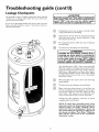
Leakage Checkpoints
A CAUTION
Use this guide to check a "Leaking" water heater. Many suspected
"Leakers" are not leaking tanks. Often the source of the water
can be found and corrected.
J
Read this manual first. Then before checking the J
water heater make sure the electric supply has been J
turned "OFF", and never turn the electric supply
"ON' before the tank is completely full of water.
If you are not thoroughly familiar with electric codes, the water
heater, and safety practices, contact a Sears Service Center to
check the water heater•
®
®
©
©
*Condensation may be seen on pipes in humid weather
or pipe connections may be leaking.
Small amounts of water from the temperature-pressure
relief valve may be due to thermal expansion or high
water pressure m your area.
*The temperature-pressure relief valve may be leaking at
the tank fitting.
The element may be leaking at the tank fitting.
A WARNING
HAZARD OF ELECTRICAL SHOCK! Before
removing any access panels or servicing the
water heater, make sure the electrical supply
to the water heater is turned "OFF". Failure
to do this could result in DEATH, SERIOUS
BODILY INJURY, OR PROPERTY DAMAGE.
"Iiirn electrical power "OFF", remove access panel and
fold back insulation. If leaking around element, follow
proper draining instructions and remove element.
Reposition or replace gasket on element• Place element
into opening and tighten securely. Then follow "Filling
the Water Heater--instructions
in the "Installation
Instructions
®
®
©
section.
Water from drain valve may be due to the valve being
opened slightly•
*The drain valve may be leaking at the tank fitting•
*Water in the water heater bottom or on the floor may
be from condensation, loose connections or the temperature-pressure relief valve. DO NOT replace the water
heater until a full inspection of all possible water
sources is made and necessary corrective steps taken•
Leakage from other appliances, water lines, or ground
seepage should also be checked.
NOTE: To check where threaded portion enters
tank, insert cotton swab between jacket opening and
fitting. If cotton is wet, follow "Draining" instructions in the "Service and Adjustment" section and
then remove fitting. Put pipe dope or teflon tape on
the threads and,,.replace" Then follow "Filling" the
Water Heater instructions
in the "Installation
Instructions" section.
21
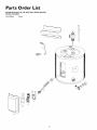
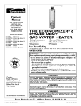
Parts Order List
153.317020
2 G_I.
1_
°__]
13
o
5
22
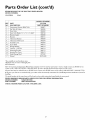
Parts Order
List (cont'd)
KENMORE POINT OF USE ELECTRIC WATER HEATER
MODEL NUMBER:
153.317020
KEY
NO.
2 Gal.
PART
DESCRIPTION
1.
2.
3.
4.
5.
6.
7.
8.
9.
10.
"l_mperature-Pressure Relief Valve
Dip "Ihbe & Gasket
Drain Valve
Drain ValveWasher (%2"x 'g_"x/_" thick)*
Element Gasket
Element
Thermostat Bracket
Thermostat w/Hi Limit
"l_rminal Cover
Access Panel
11.
12.
Wiring Bushing
Cord Set - 120 Volt
13.
14.
15.
#
Mounting Brackets
Junction Box Cover
Model Rating Platet
Manual
MODEL NUMBERS
153.317020
PART NUMBERS
9000071
9002396
9002402
9001584
9000308
9001511
9000309
9002394
9002438
9001472
9001514
9001513
9001512
9001474
0270182
184734-000
*Also available at most hardware stores.
)Replaced only on return of damaged plate.
#Not Illustrated
Now that you have purchased your Water Heater, should a need ever exist for repair parts or service, simply contact any SEARS Service
Center or call 1-800-4-MY-HOME (1-800-469-4663). Be sure to provide all pertinent facts when you call or visit.
All parts listed may be ordered from any SEARS Service Center, most SEARS stores, and by calling 1-800-366-PART (1-800-366-7278).
If the parts you need are not stocked locally, your order will be electronically transmitted to a SEARS Repair Parts Distribution Center for
handling
The model number of the water heater will be found on the model rating plate located beside the access panel.
WHEN ORDERING REPAIR PARTS, ALWAYSGIVE THE FOLLOWING INFORMATION:
MODEL NUMBER
NAME OF ITEM
PART NUMBER
PART DESCRIPTION
THIS IS A REPAIR PARTS LIST, NOT A PACKING LIST.
23
FULL 90 DAY WARRANTY
For 90 days from the date of purchase, when your Sears Kenmore
in accordance with the instructions in this manual, Sears will:
ON WATER HEAFER
water heater is installed
and operated
in a single-family
residence
1. Repair defects in material or workmanship
in this water heater, free of charge.
2. Furnish and install a new current model water heater of equal capacity and quality, free of charge, ifa leak occurs in the tank.
LIMITEDWARIb_N'ITON "[ANKSTHAT LEAK
After 90 days and through 1 year from the date of purchase for a water heater used in a single-family residence, if a leak occurs in
the tank, Sears will furnish a new current model water heater of equal capacity and quality. You will be charged for any
installation.
"Ib obtain warranty service, SIMPLY CALL 1-800-4-MY-HOME ®(1-800-469-4663).
product is in use in the United States.
This warranty applies only while this
This warranty gives you specific legal rights and you may also have other rights which vary from state to state.
SEARS, ROEBUCK
AND CO., Dept. 817 WA, HOFFMAN
ES'I'ATES, 1L 6(1179
The price of your water heater does not include a free checkup service call. On water heater installations arranged by Sears, Searswarrants the installation.
A charge will be made on service calls due to poor or incomplete installation. These include:
a. Adjusting thermostat
b. Leaks in pipes or fittings
c. Condensation
MASTER PROTECTION
AGREEMENTS
• Fast help by phone - phone support from a Sears technician on
products requiring in-home repair, plus convenient repair scheduling.
Congratulationson making a smart purchase.Yorenew Kenmor4_product is designedand manufactured foryearsof dependableoperation. But
llke all products, it may require preventivemaintenance or repair from
time to time. That's whenhaving a Master Protection Agreement can
saveyou money and aggravation.
• Power surge protection against electrical damage due to power fluctuations.
• Rental reimbursement
than promised.
Purchasea Master ProtectionAgreement now and protect yourselffrom
unexpectedhassleand expense.
if repair of your covered product takes longer
Once you purchase the Agreement,a simple phone call is all that it takes
for you to scheduleservice.You can call anytime day or night, or schedule a serviceappointment on-fine.
"l]le Master I)rotection Agreementalso helps extend the life of your new
product. Here'swhat's included in the Agreement:
Sears has over 12,000 professional repair spedalists, who have access to
over 4.5 million quality parts and accessories. That's file kind of professionalism you can count on to help prolong the life of your new purchase
for years to come. Purchase your Master Protection Agreement today!
• Expert Service by our 12,000 professionalrepairspecialists.
• Unlimited service and no charge for parts and labor on all covered
repairs.
Some limitations and exclusions apply. For prices and additional
information call 1-800-82%6655
• "No-lemon" _tee
- replacementof your coveredproduct if four
or more product failuresoccur within twelvemonths.
SEARS
INSTALLATION
SERVICE
• Productreplacement if your coveredproduct can't be fixed.
For Searsprofessionalinstallationof home appliances,garagedoor openers, water heaters and other major home items, in the U.S.A., call
1-800-4-MY-HOME®.
• Annual PreventiveMaintenance Check at your request - no extra
charge.
For in-home major brand repair
Call 24 hours a day, 7 days a week (USA
1-800-4-MY-HOME
service
and Canada)
®
(I-800-469.4663)
v_w.seaiws.eom
The model number of your water heater is found on the model rating plateon the front of the water heater.
Sears, Roebuck and Co., Hoffman
Estates, IL 60179 U.S.A.