1
i
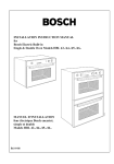
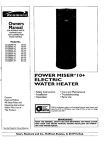
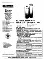
Owners
Manual
FOR POTABLE WATER
HEATING
ONLY
NOT SUITABLEFOR
SPACEHEATING
NOT FOR USE IN
MOBILE HOMES
Model No.
153.337113
153.337162
153.337213
153.337262
153.337362
153.337413
153.337462
153.337513
153.337562
153.337613
153.337662
153.337762
153.337862
153.337960
50 Gal. Short High Altitude
50 Gal. Short
40 Gal. Short High Altitude
40 Gal. Short
30 Gal.
40 Gal. High Altitude
40 Gal.
50 GaL High Altitude
50 Gal.
65 Gal. High Altitude
65 Gal.
50 Gal. High Recovery
65 Gal. High Recovery
40 Gal. (LP.)
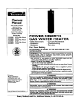
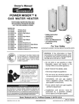
POWER
MISERTM9
GAS
WATER
HEATER
• Care and Maintenance
• Troubleshooting
• Parts List
• Safety Instructions
• Installation
•
Operation
For Your Safety
AM ODORANT
IS ADDED
WATER HEATER
TO THE GAS USED
BY THIS
WARNING:
If the information .in these instructions are not followed exactly, a .fire or explosion may result, causing property
damage, personal injury or death.
-Do not store or use gasoline or other flammable vapors and liquids in the vicinity of this or any other appliance.
-WHAT TO DO IF YOU SMELL GAS
Caution:
Read and Follow
All Safety Rules and
Operating Instructions
Before First Use of
This Product.
: Do not try to light any appliance.
Do not touch any electrical switch; do not use any phone in your
building.
.
.
,
Immediately call your _as supp.lier from a neighbor s phone.
i Follow the gas suppher's instructions.
If you can not reach your gas suppher, call the fire department.
-Installation and service must be performed by a qualified installer,
service agency or the gas supplier.
&WARNING
Improper installation, adjustment, alteration, service or maintenance
can cause DEATH, SERIOUS BODILY INJURY, OR PROPERTY DAMAGE. Refer to this manual for assistance or consult the local Sear
Service Center or gas utility for further information.
&WARNING
Flammable
vapors may be drawn
of the structure to this appliance.
Save this Manual for Future Reference.
by air currents
from
other
areas
&WARNING
READ THE GENERAL SAFETY SECTION BEGINNING ON INSIDE
COVER AND THEN THIS ENTIRE MANUAL BEFORE INSTALLING
OR OPERATING THIS WATER HEATER.
Sears, Roebuck and Co., Hoffman
Estates, IL 60179 U.S.A.
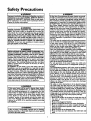
Safety Precautions
.
h'WARNING
.
I
Improper installation, adjustment, alteration, service or I
maintenance can cause DEATH, SERIOUS BODILY I
INJURY, OR PROPERTY DAMAGE. Refer to this man.ual for assistance or Consult your local Sears Service I
Center for further information.
I
i
i
," i
AWARNING
WATER HEATERS EQUIPPED FOR ONE TYPE GAS
'ONLY: This water heater is equipped for one type gas
only. Check the model rating plate near the gas control
valve for the correct gas. DO NOT USE THIS WATER
! HEATER WITH ANY GAS OTHER THAN THE ONE
SHOWN ON THE MODELRATING PLATE. Failure to
! usethe correct gascan causeproblems which can result in
I DEATH, SERIOUS BODILY INJURY, OR PROPERTY
DAMAGE. If you have any questions or doubts consult
your gassupplier or local utility.
A, WARNING
INSTALLATIONS IN AREAS WHERE FLAMMABLE LIQUIDS (VAPORS) ARE LIKELY TO BE PRESENT OR
STORED (GARAGES, STORAGE, AND UTILITY AREAS,
ETC): Flammable liquids (such as gasoline, solvents,
propane (LP) or butane, etc.), all of which emit flammable
vapors, may be impropedy stored or used in such areas.
The gas water heater pilot light or main burner can ignite
such vapors. The resulting flashback and fire can cause
death or serious burns to anyone in the area, as well as
property damage.
If installation in such areas is your only option, then the
installation must be accomplishedin a way that the pilot
flame and main burner flame are elevated from the floor
at least 18 inches. While this may reduce the chances of
flammable vapors from a floor spill being ignited, gasoline
and other flammable substancesshouldnever be stored or
used in the same room or area containing a gas water
heater or other open flame or spark producingappliance.
NOTE: Flammable vapors may be drawn by air currents
from other areas of the structure to the appliance.
AWARNING
If this water heater will be used in beauty shops, barber
shops, cleaning establishments, or self-service laundries
with dry cleaning equipment, it is imperative that the
water heater or water heaters be installed so that combustion and ventilation air be taken from outside these
areas. Refer to the "Facts to Consider About the
Location" section of this manual and also the latest edition of the National Fuel Gas Code, ANSI Z223.1, also
! referred to as NFPA 54 for specificsprovided concerning
I air required.
I
A,W..A.RNING
I
A fire can start if combustible materials such as cloth!ng,
cleaningmaterials, or flammable IKluidsare placed ag;unstI
or next to the water hea_,
J
AWARNING
At the time of manufacture this water heater _
provided with a combination temperature-pressures relief valve
certified by a nationally recognized testing laboratory
that maintains periodic inspection of production of listed
equipment or materials, as meeting the requirements
for Relief Valves and Automatic Gas Shutoff Devices for
Hot Water Supply Systems, and the latest edition of
ANSI Z21.22 and the code requirements of ASME. If
replaced, the valve must meet the requirements of local
codes, but not less than a combination temperature and
pressure relief.valve certified as meeting the requirements for Rehef Valves and Automatic Gas Shutoff
Devices fur Hot Water Supply Systems, ANSI Z21.22 by
a nationally recognized testing laboratory that maintains
periodic inspection of production of listed equipment or
materials.
The valve must be marked with a maximum set pressure
not to exceed the marked hydrostatic working pressure
of the water heater (150 Ibs./sq. in.) and a discharge
capacity not less than the water heater input rate as
shown on the model rating plate. (Electric heaters watts divided by 1000 x 3415 equal BTU/Hr. rate.)
Your local jurisdictional authority, while mandating the
use of a temperature-pressure relief valve complying
with ANSI Z21.22 and ASME, may require a valve model
different from the one furnishedwith the water heater.
Compliance with such local requirements must be satisfied by the installer or end user of the water heater with
a locally prescribed temperature-pressure relief valve
installed in the designated opening in the water heater in
place of the factory furnished valve.
For safe operation of the water heater, the relief valve
must not be removed from it's designated opening or
plugged.
The temperature-prossure relief valve must be installed
directly into the fitting of the water heater designated
for the relief valve. Position the valve downward and provide tubing so that any discharge will ex'_ only within 6
inches above, or at any distance below the structural
floor. Be certain that no contact is made with any live
electrical part. The discharge opening must not be
I
.
I
blocked or reduced • n smzeunder any cmrcumstances.
Excessivelength ever 30 feet or use of more than four
elbows can cause restriction and reduce the d_scharge
capacity of the valve.
No valve or other obstruction is to be placed between
the relief valve and the tank. Do not connect tubing
directly to discharge drain unlessa 6" air gap is provided.
To prevent bodily injury, hazard to life, or property damage, the relief valve must be allowed to dischargewater
in quantities should circumstances demand. If the discharge pipe is not connected to a drain or other suitable
means, the water flow may causeproperty damage.
The Discha_e Pipe:
Must not be smaller in size than the outlet pipe size of
the valve, or have any reducing couplings or other
restrictions.
Must not be plugged or blocked.
Must be of material listed for hot water distribution.
Must be installed so as to allow complete drainage of
both the temperature-pressure relief valve, and the
dischargepipe.
Must terminate at an adequate drain.
Must not have any valve between the relief valve and
tank,
Safety Precautions
&WARNING
AWARNING
A gas water heater cannot operate properly without the
correct amount of air for combustion. Do not install in a
confined area such a closet, unless you provide air as
shownin the "Facts to Consider About the Location" section. Never obstruct the flow of ventilation air. If you have
any doubts or questions at all, call your gas company.
Failure to provide the proper amount of combustion air
can result in a fire or explosionand can CAUSE DEATH,
SERIOUS BODILY INJURY,OR PROPERTYDAMAGE.
This water heater must not be installed directly on carpetlng. Carpeting must be protected .bya metal or wood
panel beneath the appliance extending beyond the full
width and depth of the appliance by at least 3 inches
(76.2mm) in any direction, or if the appliance is installed
in an alcove or closet,the entire floor must be coveredby
the panel. Failure to heed this warning may result in a
fire hazard.
AWARNING
AWARNING
VENT DAMPERS - Any vent damper, whether it is.operated thermally or otherwise must be removed if its use
inhibitsproper drafting ofthe water heater.
Thermally Operated Vent Dampers: Gas-fired water
heaters having thermal efficiency in excessof 80% may
produce a relatively low flue gastemperature. Such temperatures may not be high enoughto properly open thermally operated vent dampers.This would causespillageof
flue gasesand may cause carbon monoxidepoisoning.
Vent dampers must bear evidenceof certificationas complying with the latest edition of American National
Standard ANSI Z21.68 (ANSI Z21.66 & 67, respectively,
cover electrically and mechanically actuated vent
dampers). Before installationof any vent damper, consult
your localSears Service Center or the gas utility for further information.
HOTTER WATER CAN SCALD: Water heaters are
intended to produce hot water. Water heated to a tam)erature which will satisfyclothes washing,dish washing,
and other sanitizing needs can scald and permanently
injure you upon contact. Some people are more likely to
be permanently injured by hot water than others. These
includethe elderly, children,the infirm, or physically/mentally handicapped.If anyone usinghot water in your home
fits into one of these groupsor if there is a local code or
state law requiring a certain temperature water at the hot
water tap, then you must take specialprecautions.In addi.
tion to usingthe lowest possibletemperature setting that
satisfiesyour hot water needs, a means such as a mixing
valve, should be used at the hot water taps used by these
people or at the water heater. Mixing valvesare available
at plumbing supplyor hardware stores. Follow manufacturers instructions for installation of the valves. Before
changingthe factory setting on the thermostat, read the
"Temperature Regulation"section in this manual.
_,WARNING
• The applianceand its individualshutoff valvemust be disconnectedfrom the gassupply piling systemduring any
pressure testing of the gas system at test pressuresin
excessof ½pound per squareinch(3.SkPa).
• The appliance must be isolatedfrom the gas supplypiping system by dosing its individual manual shutoffvalve
during any pressuretesting of the gas supplypiping system at test pressures equal or less than % pound per
squareinch (3.SkPa).
AWARNING
Soot build-up indicates a problem that requires correction before further use. Turn "OFF" gas to water heater
and leave "OFF" until repairs are made, becausefailure
to correct the cause of the sooting can result in a fire or
explosion causing DEATH, SERIOUS BODILY INJURY,
OR PROPERTY DAMAGE.
AWARNING
AWARNING
Chemical vapor corrosion of the flue and vent system
may occurif air for combustion containscertain chemical
vapors. Spray can propellants,cleaningsolvents,refrigerator and air conditioner refrigerants, swimming pool
chemicals, calcium and sodium chloride, waxes, bleach,
and processchemicalsare typical compoundswhich are
potentially corrosive.
BEFORE LIGHTING [PROPANE (L.P.) GAS WATER
HEATERS]: Propane (I-R) gas is heavier than air. Should
there be a leak in the system,the gaswill settle near the
ground. Basements, crawl spaces, skirted areas under
mobile homes (even when ventilated), closets and areas
below ground level will serve as pocketsfor the accumulation of this gas. Before attempting to light or relight the
water heater's pilot or turning on a nearby electrical light
switch, be absolutelysure there is no accumulated gas in
the are_ Search for odor of gas by sniffingat ground level
in the vicinity of the appliance. If odor is detected, follow
steps indicated at "For Your Safety" on the cover page of
this manualthen leavethe premises.
AWARNING
Obstructed or deteriorated vent systemsmay present a
serioushealth risk or asphyxiation.
Safety Precautions continued on page 4.
3
Safety Precautions
AWARNING
_,CAUTION
I
WATER HEATERS EVENTUALLY
LEAK_ Installation of
the water heater must be accomplished in such a manner
that if the tank or any connections should leak, the flow
of water will not cause damage to the structure. For this
reason, it is not advisable to install the water heater in an
attic or upper floor. When such locations cannot be i
avoided, a suitable drain pan should be installed under
the water heater. Drain pans are available at your local
Sears store. Such a drain pan must be not greater than
1I/2 inches deep, have a minimum length and width of at
east 2 inches greater than the water heater dimensions
and must be piped to an adequate drain. The pan must
not restrict combustion air flow. Under no circumstances
is the manufacturer
or Sears to be held liable for any
water damage in connection with this water heater.
The water heater _
draft hood installed must be prep- I
erly vented to a chimney which terminates
outdoors, i
[ Never operate the water heater unless it is vented to the [
outdoors and h.as adequate air supply to avoid risks ofl
I improper operation, explosion or asphyxiation.
}
&WARNING
Minimum clearances between the water heater and combustible construction are I" at the sides and rear, 4" at the
front, and 6" from the vent pipe. Clearance from the top
of the jacket is 18" on most models. Note that a lesser
dimension may be allowed on some models. Refer to the
label on the water heater adjacent to the gas control valve
for all clearances.
I
.AWARNING
Do not
water,
Inspect
part of
use this apphance
Immediately
call
the appliance and
the bumar system
I
if any part of.it has been under
a Sears Service Technician to [
to replace the gas control or any I
which has been under water.
&WARNING
HYDROGEN GAS: Hydrogen gas can be produced in a hot
water system that has not been used for a long period of
time (generally two weeks or more). Hydrogen gas is
extremely flammable and explosive. To prevent the possibility of injury under these conditions, we recommend the
hot water faucet be opened for several minutes at the
_itehen sink before any electrical appliances which are
connected to the hot water system are used (such as a
dishwasher or washing machine), If hydrogen gas is present, there will probably be an unusual sound similar to air
escaping through the pipe as the hot water faucet is
opened. There must be no smoking or open flame near
the faucet at the time it is open.
AWARNING
INSULATING
JACKETS: When installing an external
rater heater insulation jacket on a gas water heater:
DO NOT cover the temperature-pressure
relief valve.
DO NOT put insulation over any part of the top of the
gas water heater.
DO NOT put insulation over the gas control valve or gas
control valve/burnar cover, or any access areas to the
burner.
DO NOT let insulation around the gas water heater to
get within 8 inches of the floor (air must get to the
burner).
DO NOT cover or remove operating instructions, and
safety related warning labels and materials affixed to the
water heater.
Failure to heed this will result in the possibility of a Ere or
Iexplosion.
4
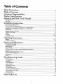
Table of Contents
Safety Precautions .....................................................................................................
2.
Table of Contents ......................................................................................................
5
Customer Re.s_onsibilities .......................................................................................
6
Product Specincations ..............................................................................................
6
Materials and Basic Tools Needed ............................................................................................... 7
Materials Needed ......................................................................................................................................................................
Basic Tools ................................................................................................................................................................................
"Installation
--"
Instructions
.......................................................................................................
8-16
Removing the Old Water Heater ...............................................................................................................................................
Facts to Consider About the Location .......................................................................................................................................
Combustion Air and Ventilation for Appliances in Unconfined Spaces ...................................................................................
Combustion Air and Ventilation for Appliances in Confined Spaces .......................................................................................
Water Piping ...........................................................................................................................................................................
Tempe,_tu_-Pressure
l_lief Valve ...........................................................................................................................................
Filling the Water Heater ..........................................................................................................................................................
Venting ..............................................................................................................................................................................
Gas Piping .........................................................................................................................................................................
Installation Checklist ..............................................................................................................................................................
---Operating Instructions
8
9
10
10
11
12
13
13-14,
14-15
16
..................................................................................................
17-19
Fighting ......... 7...............................................................................................................................................................
Temperature Regulation ..........................................................................................................................................................
Service and Adjustment
7
7
[-.17-18
19
......................................................................................................................
20-22
Tank (Sediment) Cleaning ......................................................................................................................................................
Venting System Inspection ......................................................................................................................................................
Burner Inspection ...................................................................................................................................................................
Burner Cleaning .....................................................................................................................................................................
L.E Gas Control Valve & Burner Assembly Replacement Information ....................................................................................
Draining .................................................................................................................................................................................
Temperature-Pressure
Relief Valve Operation ..........................................................................................................................
Drain Valve Washer Replacement ...........................................................................................................................................
Housekeeping .........................................................................................................................................................................
Service ....................................................................................................................................................................................
20
20
20
20
21
21
21
22
22
22
Troubleshooting
Guide ............................................................................................
23-25
Start Up Conditions ...............................................................................................................................................................
Condensation ........................................................................................................................................................................
Smoke/Odor .........................................................................................................................................................................
Thermal Expansion ...............................................................................................................................................................
Strange _un& ......................................................................................................................................................................
Operational Conditions ..........................................................................................................................................................
Smelly Water .........................................................................................................................................................................
Air in Hot Water Faucets ......................................................................................................................................................
High Temperature Shut Off System ......................................................................................................................................
Not Enough or No Hot Water ..............................................................................................................................................
Water is too Hot ...................................................................................................................................................................
23
23
23
23
23
24
24
24
24
24
24
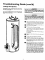
Leakage Checkpoints
25
..............................................................................................................................................................
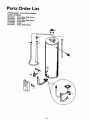
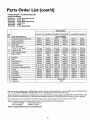
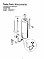
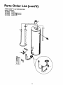
Parts ---Order
List...................................................................................................
28-35
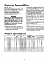
Customer
Responsibilities
Thank You for
This manual contains instructions for the installation, operation, and maintenance of the gas-fired water heater. It also
contains warnings through out the manual that you must read
and be aware of, All warnings and all instructions are essential
to the proper operation of the water heater and your safety.
Since we cannot put everything on the first few pages, READ
THE ENTIRE MANUAL BEFORE ATTEMPTING TO
INSTALL OR OPERATE THE WATER HEATER.
The installation must conform with the instructions in this
manual; gas company rules; and Local Codes, or in the
absence of Local Codes, with the latest edition of the National
Fuel Gas code, ANSI Z223.1, also referred to as NFPA 54.
This publication is available from your local government or
public library or gas company or by writing NFPA,
Battetymarch Park, Quincy, MA 02269.
If after reading this manual you have any questions or do not
understand any portion of the instructions, call the Sears
Service Center.
Carefully plan the place where you are going to put the water
heater. Corsect combustion, vent action, and vent pipe installation are very important in preventing death from possible
carbon monoxide poisoning and fires.
Examine the location to ensure the water heater complies with
the "Facts to Consider About the Location" section in this
purchasinga
Sears water heater.
Properly installed and maintained, it should give you years of
trouble free service. If you should decide that you want the new
water heater professionally installed by Sears call the local Sears
Service Center or any Sears store. They will arrange for prompt,
quality installation by Sears authorized contractors.
Abbreviations Pound In This Instruction Manual
I.A.S. - International Approval Services, A Division of CSA
A.N.S.I. - American National Standards Institute
N.EEA. - National Fire Prevention Association
AWARNING
This gas.fired water heater is design certified by the
International Approval Services,A Division of CSA under
American National Standard/CSA Standard for Gas Water
Heaters ANS Z21.10.1 • CSA 4.1 (latest edition). The
installation must conform with this manual, Local Codes
and with the latest edition of the National Fuel Gas Code,
ANSI Z223. I.
This pubhcationisavailable from your local.g_.ernment or
public library, gas company, or by writing NFPA,
Batterymarch Park, Quincy,MA 02269.
manna].
For California installation this water heater must be braced,
anchored, or strapped to avoid falling or moving during an
earthquake. See instructions for correct installation procedures. Instructions may be obtained from your local dealer,
wholesaler, public utilities or California Office of the State
Architect, 400 P Street, Sacramento, CA 95814.
• Read the "Safety Precautions" section, pages 2 through 4 of
this manual first and then the entire manual carefully. If you
don't follow the safety rules, the water heater will not operate
PNjroperly.It could cause DEATH, SERIOUS BODILY
URY AND/OR PROPERTY DAMAGE.
Product
MODEL NUMBER
153.337113
153.337162
153.337213
153.337262
153.337362
153.337413
153.337462
153.337513
153.337562
153.337613
153.337662
153.337762
153.337862
153.337960
Specifications
TANK
CAPACITY
IN GALLON_
50
50
40
40
30
40
40
50
50
65
65
50
65
40
TYPE
OF
GAS
NATURAL
NATURAL
NATURAL
NATURAL
NATURAL
NATURAL
NATURAL
NATURAL
NATURAL
NATURAL
NATURAL
NATURAL
NATURAL
PROPANE
RECOVERY
B.T.U.
RATE
40,000
40,000
40,000
40,000
40,000
40,000
40,000
40,000
40,000
40,000
40,000
52,500
50,000
40,000
6
RATE GAI.S.
, PER HOUR
@90OF RISE
4O.9
MINIMUM
VENT
PIPE
40.9
40.9
3"
3"
3"
3"
40.9
40.9
40.9
3" or 4"
Y' or 4"
3" or 4"
40,9
40,9
3" or 4"
40.9
40,9
40.9
53,7
51.2
40.9
or
or
or
or
4"
4"
4"
4"
3" or 4"
3" or 4"
Y' or 4"
4"
4"
3" or 4"
DIMENSIONS IN INCHES
HEIGHT TO
DIAMETER ACKET TOP
22"
22"
20"
20"
16"
18"
18"
20"
20"
22"
22"
20"
22"
18"
49"
49"
47½"
47½"
57½"
58¼"
58W'
58"
58"
59½"
59½"
58¾"
59'A"
58¼"
Materials
Materials
and Basic Tools Needed
Needed
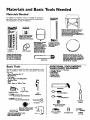
To simplify the installation Sears has available the installation
parts shown below. You may or may not need all of'these materials, depending-on your type of installation.
WATER HEATER STAND 24"x24"xl 8"
FOR USE WITH WATER HEATERS
INSTALLED IN RESIDENTIAL
GARAGES HAVING A DIAMETER 24"
OR LESS AND A RATED CAPACITY 75
GALLONS OR LESS
_i_ a//a//on
THERMAL
@
VENT ELBOW
WATER HEATER INSTALLATIOH KIT WITH FLEXIBLE CONNECTORS
FOR
3/4" OR I/2" THREADED
OR COPPER PLUMBING
EXPANSION TANKS
FOR THERMAL
EXPANSION
CONDITIONS AVAILABLE IN
2 GALLON AND 5
GALLON CAPACITY
THROUGH
LOCAL
SEARS STORE OR
SERVICE CENTERS
FLEXIBLE WATER
HEATER GAS CONNECTOR WITH
FITTINGS
DRAIN PANS AVAILABLE IN 20"
DIAMETER FOR WATER HEATERS
HAVING A DIAMETER 18" OR LESS
AND AVAILABLE IN 28" DIAMETER
FOR WATER HEATERS HAVING A
DIAMETER 26" OR LESS
C
VENT
Basic Tools
You may or may not need all of these tools, depending on your
type of installation. These tools can be purchased at your local
Sears store.
•
•
•
•
•
•
•
O
SYPHONING
Pipe Wrenches (2) 14"
Screwdriver
Tin Snips
6 Foot Tape of Folding Rule
Garden Hose
Drill
Pipe dope or Teflon Tape
PIPE
ADDITIONAL
TOOLS NEEDED
WHEN
SWEAT SOLDERING
• Tubing Cutters
• Propane
Torch
Sof_ Solder
• Solder Flux
• Emery Cloth
• Wire Brushes
or Hacksaw
HACKSAW
GARDEN
HOSE
6 FOOT TAPE
PIPE
WRENCH
SLOT-HEAD
314" WIRE BRUSH
SCREWDRIVER
I/2" WIRE BRUSH
PHILLIPS
SCREWDRIVER
PROPANE
TORCH
TIN SNIPS
ROLL OF LEAD FREE
SOFT SOLDER
8
ROLL OF TEFLON TAPE
(USE ONLY ON WATER
CONNECTIONS)
PIPE DOPE (SQUEEZE TUBE)
USE FOR WATER AND
_AS CONNECTIONS)
ROLL OF EMERY
CLOTH
SOLDER FLUX
TUBING
CUTTER
Installation
Instructions
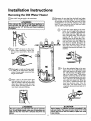
Removing the Old Water
Heater
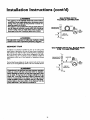
Turn _OWW"the gas supply to the water heater.
Disconnect the vent pipe from the draft hood where
they connect to the water heater. In most installations
the vent pipe can be lifted off after any screw or other
attached devices are removed. Dispose of the draft
hood. The new water heater has the draft hood which
must be used for proper operation.
AWARNING
. ]
I If the main gas line shutoff serving all gas appliances is I
[ used, also shut "off" the gas at each appliance. Leave all ]
gasappliances shut "off" until the water heater installation|
[is complete.
I
®
Turn "OFF" the water to the water
heater. Some installations require that
the water be turned off to the entire
a.
If you have copper piping to the water
heater, the two copper water pipes can
be cut with a hacksaw approximately
four inches away from where they connect to the water heater. This will avoid
cutting
off the pipes too short.
Additional cuts can be made later if necessary. Disconnect the temperature-pressure relief valve drain line. When the
water heater is drained, disconnect the
hose from the drain valve. Close the
drain valve. The water heater is now
completely disconnected and ready to be
removed.
house.
If you have galvanized pipe to the water
heater, loosen the two galvanized pipes
with a pipe wrench at the union in each
line. Also disconnect the piping remaining to the water heater. These pieces
should be saved since they may be needed when reconnecting the new water
heater. Disconnect the temperature-pressure relief valve drain line. When the
water heater is drained, disconnect the
hose from the drain valve. Close the
drain valve. The water heater is now
completely disconnected and ready to be
Check a[,ain to make sure the gas supply
is "OFF
to the water heater. Then disconnect the gas supply connection from
the gas control valve.
G
Attach a hose to the water heater drain
valve and put the other end in a floor
drain or outdoors. Open the water heater
drain valve. Open a nearby hot water
faucet which will relieve pressure in the
water heater and speed draining.
remove.
AWARNING
The water passingout of the drain valvemay be extremely
hot. To avoidbeing scalded,make sure all connectionsare
tight and that the water flow is directed away from any
person.
IL"
A CAUTION
meral buildupor sediment may have accumulatedin the i
d water heater.This causesthe water heater to be much
eavier than normal and this residue,if spilled out, could
se staining.
8
Installation
Instructions
Facts to Consider
Location
About the
You should carefully choose an indoor location for the new
water heater, because the placement is a very important consideration for the safety of the occupants in the building and for
the most economical use of the appliance. This water heater is
not for use in mobile homes or outdoor installation.
Whether replacing an old water heater or putting the water
heater in a new location, the following critical points must be
observed.
'
•
The location selected should be indoors as close as practical
to the gas vent or chimney to which the water heater vent is
going to be connected, and as centralized with the water piping system as possible. The water heater, as all water heaters,
will eventually leak. Do not install without adequate
drainage provisions where water flow will cause damage.
A CAUTION
WATER HEATERS EVENTUALLY LEAK: Installationof the
water heater must be accomplishedin sucha mannerthat if
the tank or anyconnectionsshouldleak, tee flow of water will
not causedamageto the structure.For this reason,it is not
to installthe water heater in an attic or upperfloor.
When suchlocationscannot be avoided,a suitabledrain pan
shouldbe installedunder the water heater. Drain pans are
availableat your load Searsstore.Sucha drain pan must be
not grenterthen I Y2inchnsdee_ havea mlnlmum kmgthand
of at least2 inchesgreaterthan the water heater dimensions_ mustbe pipedto an adequate drain.The pan must
not restrictcombestionair flow.Under no drcumstaneasisthe
manufactureror Searsto be heldliablefor anywater damage
in €onnectinnwith this water beater.
AWARNING
INSTALLATIONSIN AREASWHERE FLAMMABLEUQUIDS
(VAPORS) ARE lIKELY TO BE PRESENT OR STORED
(GARAGES, STORAGE, AND UTILITY AREAS, ETC):
Flammableliquids(suchas gasoline,solvents,propane(LP) or
butane, etc.), all of which emit flammable vapors, may be
improperlystoredor usedin suchareas.The gaswater heater
pilot light or mainburner am ignitesuch vapors.The resulting
Rashbeck
andfire cancausedeathor seriousburnsto anyonein
the area,aswellesproperty_.
If inst_latienin suchareasisyouronlyoption,then the ias_dintion must be aCcomplished
in a way that the pilot flame and
main burner eameam elevatndfrom theflenr at least18inche_
While this n_/reduce the chancesof flammablevaporsfrom a
floor sp,Ibeingignited,gasolineand otherflammablesubmmces
shouldneverbe storedor usedin the sameroom or area contalninga gaswater heater or otheropenflameor sparkproducingappliance.
NOTE: Flammablevaporsmay be drawnby air currentsfrom
otherereusof the structureto tim appliance.
AWARNING
Propellants of anrosol spraysand volatilecompounds,(cleaners, chlorinebasedchemicals,refrigerants,etc.) in additionto
being highlyflmnmable.in manycases,will alsochangeto .corrosive hydroch|orlcacid when exposedto the combustion
productsof the water heater.The resultscan be hazardous,
and also cause productfailure.
(cont'd)
• The location selection must provide adequate clearances for servicing and proper operation of the water heater.
AWARNING
Thiswater heater mustnot be installeddirectlyon earpeting.
Carpeting must be protected by a metal or wood panel
beneath the app lance extendingbeyond the ful _dth and
depth of the appliance by at least 3 inches(76.2mm) in any
direction,or if the applianceis installedin an akove or duset,
the entire floor mustbe coveredbythe paneLFailureto heed
this warningmay resultin a fire hazard.
AWARNING
Minimum clearances between the water heater end combustibleconstructionare I" at the r_dusand rear, 4" at the
frout, and 6"from the vent pipe.Cleanmcefrom the tep of the
_cket is 18"on most models.Note that a lesserdimensionmay
be allowedon somemodek. Refer to the labelon the water
heateradjacentto thegascontrolvalvefor alldearance_
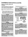
VENT_TION
OPENINGS
I Figure ! I
AWARNING
A gaswater heater cannotoperateproperlywithoutthe correct amount of air for combustion.Do not installin a confined
area sucha duset, unlessyou provideair as shownin Figures
I-5. Never obstructthe flow of ventilationair. If you haveany
doubtsor questionsat all,callyourgascompany.Failureto providecheproper_mt
ofcombes6on air am resultin a life or
explosionand can causeDEATH, SERIOUSBODILY INJUI_,
OR PROPERTYDAMAGE.
AWARNING
If thiswater heater wifibe usedin beautyshops,barber shops,
cleaning establishments,or self-servicelaundries with dry
cleaningequipment,it is imperativethat the water heater or
wa_erheaters be installed so that combustion and ven_
Bir be taken from outsidethese areas.Refer to the "Facts to
ConsiderAbout the Location"sectionof this manualand also
the latestedition of the NationalFuelGasCode,ANSI Z223.1,
also referred to as NFPA 54 for specificsprodded concerning
air required.
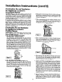
Installation
Combustion
Instructions
(cont'd)
Air and Ventilation
for Appliances Located in
Unconfined Spaces
Unconfined Space is a space whose volume is not less than 50
cubic feet per 1,000 Btu pet hour of the aggregate input rating
of all appliances installed in that space. Rooms communicating
directly with the space in which the appliances are installed,
through openings not furnished with doors, ate considered a
part of the unconfined space
In unconfined spaces in buildings, infiltration may be adequate
to provide air for combustion, ventilation and dilution of flue
gases. HoWever, in buildings of tight construction (for exampl€,
weather stripping, heavily insulated, caulked, vapor barri€r, etc.),
additional air may need to be provided using the methods
described in Combustion Ait and Ventilation t'orAppliances
Located in Confined Spaces, b.
1. When directly communicating
with the outdoors, each opening shall have a minimum free areaof 1 square inch per 4,000
BTU per hour of total input rating of all equipment in the
€ndosure. (See Figure 3.)
2. When communicating
with the outdoors through vertical
shall have a minimum free area of 1
square inch per 4,000 BTU per hour of total input rating of
all equipment in the endosure. (See Figure 4.)
ducts,
each opening
_L_IEy
Off Otd
V_Tga_'flO_
VEIcr
LO_EF*O
Combustion Air and Ventilation
for Appliances Located in
Confined Spaces
Confined Space is a space whose volume is less than 50 cubic
feet per 1,000 Bm per hour of the aggregate input rating of all
appliances installed in that space.
a. ALL AIR FROM INSIDE BUILDINGS.
(See Page9 Figure 1, and Figure2 below)
The €onfined space shall be provided with two permanent
openings communicating directly with an additional room(s)
of suiTlcient volume so that the combined volume of all
spaces meets the criteria for an unconfined space. The total
Figure 4 ]
3. When communicating with the outdoors through horizontal
ducts, each opening shall have a minimum free area of l
alsctuare
inch per 2,000 BTU per hour of total input rating of
equipment in the enclosure. (See Figure 5.)
input of all gas utilization equipment installed in the combined space Mall be considered in making this determination.
Each opening shall have a minimum free area of one square
inch per 1,000 BTU per hour of the total input rating of all
gas utilization equipment in the confined space, but not less
than 100 square inches. One opening shall commence within
12 inches of the top and one commencing within 12 inches
of the bottom of the enclosure.
Figure 5 ]
4. When ducts are used, they shall be of the same cross-sectional
area as the free area of the openings to which they connect.
The minimum short side dimension of rectangularair ducts
shall not be less than 3 inches. (See Figure 5.)
5. Louvers and Grilles: In calculating free area, consideration
shall be given to the blocking €ffect of louvers, grilles or
screens protecting openings. Screens used shall not be smaller
than ¼ inch mesh. If the Free area through a design of louver
or grille is known, it should be used in calculating the size
opening required to provide the free area specified. If the
design and free area is not known, it may be assumed that
wood louvers will be 20-25 percent free areaand metal louvers
and grilles will have 60-75 percent free area. Louvers and
grilles shall be fixed in the open position or interlocked with
the equipment so that they are opened automatically during
equipment operation.
b. ALL AIR FROM OUTDOORS: (see Figures 3-5)
The confined space shall be provided with two permanent
openings, one commencing within 12 inches of the top and
one commencing within 12 inches from the bottom of the
enclosure. The openings shall communicate directly, or by
ducts, with the outdoors or spaces (crawl or attic) that freely
communicate with the outdoors.
6. Special Conditions Created by Mechanical Exhausting or
Fireplaces: Operation of €xhaust fans, ventilation systems,
clothes dryers or fireplaces may create conditions requiring
special attention to avoid unsatisfactory operation of installed
gas utilization equipment.
IFI re']
10
Installation
Water
Instructions
(cont'd)
Piping
•
AWARNING
HOTTER WATERCAN SCALI_.Water heatersam intendedto
producehotwater.Water heatodto a W.._yhi_
*dll
satisfydod_ washln&dishwashin&and othersanitizingneeds
(an scaldand permanentlyInjureyouuponcontact.Some peo_e are more likely to be penmanentlyinjuredbyhot water b_an
otherL Theseincludethe eklerl_chlldmrkthe infirm,or physically/mentallyhandicapped.
If anyoneusinghot water in yourhome
fitsinto oneulthese greupsor If thereisa local€odeor statelaw
requiringa certaintemperaturewaterat _ hot waterta_ then
mumusttake specialpmceutienLIn addidouto usingtbe lowest
x_ibin temperaturesettingthat sallsfies
yourhot waterneeds,
Lmeanssuchasa mixingvalve,shouldbe usedat the hot water
tapsusedbythese peoph or at the water heatenMixingvalves
are availableat plumbingsupplyor hardwarestore_Followmanufacturers instructions for installationof the valves.Before
changing the factory setting on the thermostat, read the
_l'emperatore Regulation"
sectionin this manual.
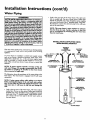
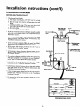
Look at the top cover of the water heater. The cold water
inlet is marked-cold. Put two or three turns of teflon tape
around the threaded end of the threaded-to-sweat coupling
and around both ends of the ¾" threaded nipple. Using flexible connectors, connect the cold water pipe to the coldwater
inlet of the water heater.
NOTE: This water heater is super insulated m
heat loss from the tank. Further reduction
in heat loss
can be accomplished
by insulating
the hot water lines
from the water heater.
INSTALLATION
COMPLETED USING
SEARS INSTALLATION
KIT
FLEXIBLE
WATER
CONNECTORS
This water heater shall not be connected to any heating systems
or component(s)
used with a non-potable
water heating
appliance.
SHUTOFF
VALVE
HOT OUTLET
If a water heater is instal|ed in a dosed water supply system;
such as one having a back-flow preventer, check valve, water
meter with a check valve, etc.., in the cold water supply; means
shall be provided to control thermal expansion.
Contact
the
local utility or local Sears Service Center on how to control this
situation.
TO HOUSE
WATER LINE
COLD INLET
/
THREADED TO
SWEAT COUPLING
THREADED
TO
SWEAT COUPLING
314" THREADED
COUPLING
314" THREADED
COUPLING
NOTE: To protect against untimely corrosion of hot and
cold water fittings, it is strongly recommended that all-electric unions or couplings be installed on this water heater
when connected to copper pipe.
The illustration shows the attachment of the water pipin_ to the
water heater. The water heater is equipped with ¼ inch water
connections.
PRESSURE
RELIEF VALVE
NOTE: If using copper tubing, solder tubing to an adapter
before attaching _e adapter to the cold water inlet enunection. Do not solder the cold water supply line directly to the
cold water inlet. It will harm the dip tube and damage the
tank.
•
PiPE (Do not cap
or plug)
[]
Look at the top cover of the water heater. The water oudet is
marked hot. Put two or three turns of teflon tape around the
threaded end of the threaded-to-sweat
coupling and around
both ends of the ¾ threaded nipple. Using flexible connectors, connect the hot water pipe to the hot water oudet on
the water heater.
6" AIR GAP
FLOOR
11
DRAIN
Installation
Instructions
Temperature-Pressure
(cont'd)
Relief Valve
_WARNING
AWARNING
The temperature-pressure relief valve must be manually
operated at least once a yea_ Caution shouldbe taken to
ensurethat (I) no one is in front of or aroundthe outlet of
the temperature-pressurerelief valvedischargeline, and (2)
the water manually dischargedwill not causeany bodily
injury or property damage because the water may be
extremely hot.
At the time of manufacturethis water heater was provided
with a combinationtemperature.pressures
raliofvalvecertified
by a nationallyrecognized testing laboratorythat maintains
.p_'odic inspectionof productionof listedequipmentor metermals,as meeting the requirements for Relief Valves and
AutomaticGasShutoffDevicesfor Hot Water SupplySystems,
and the latest edition of ANSI Z21.22 and the code require!mentsof ASME. If replaced,the valvemust meet the requiremenu ofIoealcodes,but not lessthana combinationtemperature and pressurerelief valvecertifiedas meetingthe requirementsfor ReliefValvesand AutomaticGasShutoff Devicesfor
Hot Water SupplySystems,ANSI Z21.22bya nationallyrecognizad testing laboratorythat mmntainsperiodicinspectionof
productionof listedequipment or materials.
The valvemust he markedwith a maximum sat pressureloot
to exceedthe marked hydrostaticworking pressureof the
water heater(IS0 II_J_, in.) and a discharge
capacitynot less
thanthe water heater inputrate asshownon the modelrating
plate. (Electric heaters• watts dividedby 1000x 3415 equal
BTU/Hr.rate.)
Yourlocaljurisdictional
anthori_, whilemandating the useofa
temperature-pressure
relief valvecomplyingwith ANSI Z21.22
and ASME, may require a valvemodeldifferentfrom the one
fomishedwith the wakerheater.
Compliancewith suchlocalrequirementsmustbe satisfiedby
the installeror end userof the water heaterwith a locallyprescribedtemperature-pressure
relief valveinstalledin the desig.
nated openingin the water heater in placeof the factory furnisbedvalve,
Forsafeoperationofthe water heater,the reliefvalvemustnot
beremovedfrom it_ designated
openingor plugged,
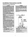
IThe temperature-pressure
reliefvalvemustbe installeddirectly
intothefittingofthewaterheaterdesignated
for the reliefvalve.
Positiontile valvedownwardend providetubingsothat anydischargewill exit onlywithin 6 inchesabove,or at any distance
belowthe structuralfloor.Be certainthat no contact ismade
with anyliveelectricalpart. The discharge
openingmustnot be
blockedor reducedin size underanycircumstances.
Excessive
length,over30 feet,or useof more than fourelbowscancause
restflcdonandreducethedischarge
capacityofthe valve.
No valveor otherobstructionisto he placedbetweenthe relief
valveand the tank. Do not connecttubingdirectlyto discharge
drainunless
a 6" air gapisprovided.Topreventbodilyinjury,hez.
ard to life,or propertydamagethe reliefvalvemustbe allowed
to discharge
water in quantitiesshouldc_rcumstances
demand.If I
the discharge
pipeisnot connectedto a drainor othersuitable
means,the waterRowmaycausepropertydamage,
The DischargePipe:
• Mustnot be smallerin sizethan the outlet pipesize of the
valve,or haveanyreducingcouplings
or otherrestrictions.
• Mustnet be pluggedor blocked.
• Mustbe ofmateriallistedfor hot water distribution.
I. Must be installedso as to allowcompletedrainageof both
the temperature.pressurerelief valve, and the discharge
If after manuallyoperating the valve, it failsto completely
resetand continuesto releasewater,immediatelydose the
cold water inlet to the water heater, follow the draining
instructions,and replace the temperature-pressure relief
valvewith a newone.
HOT
SHUTOFF
VALVE
COLD
"EHPERATUREPRESSURE
RELIEF VALVE
(Do not cap or plus)
[]
6" AIR GAP
RELIEFVALVEOPENING
At the time of _ocu_,
thiswater heater was provided with a combinationtemperature-pressurerelief valvelisted ascomNyfeg with the standa_l for rdiet" valvesand
automatic gas shut-off devices for hot war_r supply systems,ANSi Z21.22. For safe
operation of the water heater,the _lef valvemust not be removed from its designated
ypOouint
of instaibtion cr plugged.
r load urisdictiona{authori_, while mandatingthe use of a tem_rature-pre_sure
re{ief valvecomplyingwith ANSI 7-.21,22andASPIE,may require a _alve model dfferent
from the one furnishedwith the water heater
Compliancewith suchlocal requirements must be satisfied by the ins_ler or end user
of the water heater with a locallyprescril_ temperature-pressure relief valveinstalled
in the designatedopeningin the water heater
See manual heading-'q'ernperature-FYessure
Relief Valves"for instalbtion and maintenance of relief valve,dischargeline, and other safer7 precautions.
pipe.
• Mustterminateat an adequatedrain.
• Mustnot haveanyvalvebetweenthe reliefvalveand tank.
12
Installation
Filling the Water
Instructions
(cont'd)
Heater
For proper venting in certain installations, a larger diameter vent
pipe may be necessary. Due to great variances in installations,
unforeseeable by the manufacturer of the water heater, you must
consult your gas company to aid you in determining the proper
venting for your water heater from the vent tables in the latest edition of the National Fuel Gas Code ANSI Z223.1, also referred to
as NFPA 54.
A CAUTION
Never usethisvrat_r heater unlessit iscompletelyElled with I
water. To preve_ damnge to the tenk, the tenk must be filled I
with water. Water must flow from the hot water faucet
before turn ng ' ON ' gas to the water beater.
To fill the water heater with water:
• Close the water heater drain valve by turning the handle to
the right (clockwise). The drain valve is on the lower front of
the water heater.
Open the cold water supply valve to the water heater.
NOTE: The cold water supply valve must be left open
when the water heater is in use.
To insure complete filling of the tank, allow air to exit by
opening the nearest hot water faucet. Allow water to tun
until a constant flow is obtained. This will let air out of the
water heater and the piping.
• Check all new water piping for leaks. Repair as needed.
Check the venting system for signs of obstruction or deterioration
and replace if needed.
The combustion
and ventilation air flow must not be obstructed.
AWARNING
Obstructedor deter_ratedventsystems_
healthriskor asphyxiation.
presenta serious
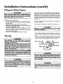
• Place the draft hood legs in the receiving holes on the top of
the water heater. The legs will snap in the holes to give a tight
fit.
• Place the vent pipe over the draft hood. With the vent pipe in
position, drill a small hole through both the vent pipe and
draft hood. Secure them together with a sheet metal screw.
Venting
Ai.WARNING
VENT DAMPERS - Any vent damper, whether it is operated
thermally or otherwise must be removed if its use inhibit3 proper drafting of the water heate_.
Thermally Operated Vent Dampers: Gas-fired water heaters
having thermal efficiency in eacess of 80% may produce a relatively low flue gastemperature. Such temperatures may not be
high enough to properly open thermally operated vent
dampers. This wonld ceuse spillageof flue gasasand rnay canse
ced_on monoKide poisoning.
Vent dampen must bear evidenceof certification as complying
with the latest edition of American National Standard ANSI
Z21.68 (ANSI Z21.66 & 67, respecd_, cover electrically and
mechanically actuated vent dampers). Before installationof any
vent dampe_ comuit your local Sears Service Center or the gas
utility for further information.
DRAFT HOOD
....
_
_VENT'_I
_
ISCRE__._I
--a
I _'
_ DRAFT HOOD
L_VENT TO OUTDOORS OR
DRAFT
HC_Off'-J_-cH''NtY
A, WARNING
I The water heater with draft hood inmdled must be properly I
vented to a chimney which terminates outdoor_ Never oper-
I ate the waterheateranlessit isventedto tbe ontdonrs andhasI
I edequateair .su.
pPlyte aveidrisksof improperoperation,explo-I
I
&WARNING
To insure proper venting of this gas-firedwater heater,the
correctvent pipediameter mustbe utilized.Any additionsor
deletionsof other gasapplianceson a commonvent with this
water heater may adversely_q_ct the operationof the vm_r
heater,Consultthe localSearsService Center or gasutility if
any suchchangesareplanned.
I
AWARNING
I
The vent pipe from the water heater must be no lessthan the I
diameter of the draft hood outlet on the water heater, and
13
Installation
Instructions
Venting (cont'd)
(cont'd)
Gas Piping
All vent gases must be completely vented to the outdoors of the
structuze (dwelling). Installonly the draft hood provided with
the new water heater and no other draft hood.
Vent pipes must be secured at each joint with sheet metal screws.
AWAJRNING
Hake sure the gas suppliedis the same type listed on the
model rating plate. The inlet gaspressuremust not exceed
10.5in.water column (2.6kPa)for natural gasor 13 in. water
column (3.2kPa) for propane(/E) gas. The minimum inlet
gaspressureI"
..L_ on the model rating plate is for the purposeofinput adlUStmant.
TO
CHIMNEY
I
l
VENT PIPE INSTALLATION
AWARNm(;
I
If the gascontrolvalveis subjectedto pressuresexceeding½
poundper squareinch(3.5kPa), the _
to the gascon- [
trnl valvecouldresultin a fire or explosionfrom leoldnggas. I
There must be a minimum of 6" cleaeance between single wall
vent pipe and any combustible material. Fill and seal any dearance between single wall vent pipe and combustible material
with mortar mix, cement, or other noncombustible substance.
For other than single wall, follow vent pipe manufacturer's clearance specifications. To insure a tight fit of the vent pipe in a
brick chimney, seal around the vent pipe with mortar mix
cement.
AWAR_I. ING
I
[ If the main gasline shutoffsorwng all gasappliancesis used,I
alsoturn "of/" the gasat eachappi.uu_e..Leaveall gasappiiI antes shutoffuntil the water heater matailationiscomplete. I
A gas line of su_cient size must be run to the water heater.
Consult the latest edition of National Fue! Gas Code ANSI
Z223.1, also referred to as NFPA 54 and the gas company concerning pipe size.
AWARNING
Failureto have required clearancesbetween vent pipingand
€ombusttl_ematerial will resultin a fire hazard.
There must be:
• A readily accessible manual shut off valve in the gas supply line
serving the water heater, and
• A drip leg (sediment trap) ahead of the gas control valve to hdp
prevent dirt and foreign materials from entering the gas control
Valve.
prexentescapeof
I Be surevent Ixpe
. is prnperlyconnectedto
AWARNING
I
• A flexible gas connector or a ground joint union between the
shutoff valveend control valve to permit servicing of the unit.
dangerousflue gaseswhichcouldcausedeadly_spl_dation.
Be sure to check all the gas piping for leaks before lighting the
water heater. Use a soapy water solution, not a match or open
flame. Rinse offsoapy solution and wipe dry.
AWARNING
Chemical vapor corrosionof the flue and vent system mm/
Occurif air for combustioncontainscertain chemicalvapor_
Spray can propellants,cleaningsolvents,refrigerator and air
conditioner refrigerants,swimmingpool chemicals, caJcium
and sodiumchloride,waxes,bleach,and processchemicalsare
typicalcompoundswhich are petandally corrosive.
Standard Models are for installation up m 3,300 feet above sea
level.
Altitude Mode_ are for installation from 3,300 to 5,500
feet abovesea level.
Ifa standard model is installed above 3,300 feet or a high aldmde
model is installed above 5,500 feet, the input rating must be
reduced at the rate of 4 percent for each 1,000 feet above sea levd,
Contact your local Sears Service Center or gas utility for further
information.
_,WARNING
The appliance and its gas connection must be leak tested
beforeplacing the appliancem operation.
14
Installation
Instructions
(cont'd)
GAS PIPING WITH
FLEXIBLE CONNECTOR
AWARNING
. Tbe appEanceaed its individueJsbetoff valve must be disconnected from the gassupply piping sym_n during any pressure
testing of the gas system at test pressures in excess of 'A
pound per squareinch (3.5k1%).
LOOP
. The appliancemustbe isobtedfromffm gassupplypipingsystem by dosing i_ individual manual shutoff valve during any
GROUND
UNION(Optional)
pr--_ure tosting of the gas supply piping system at test pressuresequal or lessthan _ pound per square inch (3.SkPa_
GAS
CONTROL
VALVE
DRIP LEG
(Sedimenttrap)
I
AWARNING
I
Use pipe joint compound or teflon tape marked as being
resistantto tbe actionof peU'oleum[Propane(LR)] gases. I
SEDIMENT
CAP
TRAP
GAS PIPING WITH ALL BLACK
PIPE TO GAS CONTROL
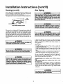
A sediment trap shall be installed as close to the inlet of the
water heater as practical at the time of water heater installation.
The sediment trap shall be either a tee fitting with a capped nip
pie in the bottom outlet or other device recognized as an effective sediment trap. If a tee fitting is used, it shall be installed in
conformance with one of the methods of installation shown
below.
GROUND IO!NT - _
UNION(Op_on_)
__
Connecting the gas piping to the gas control valve of the water
heater can be accomplished by either of the two methods shown,
IRON
BLACK PIPE
/
COTVALvP_EO
N
L
3"
AWARNING
Contaminonts in the gas lines may cause improper operatinn
of the gas €ontrol valve that may rasult in Ere or explosion.
Bofore attaching tbe gas line be sure that afl Ips pipe is dean
on the imide. To trap any dirt or foreign n_ter_l
in the gas
supply line, a drip leg (sometimes called a sediment trap)
must be incorporated in the piping. The drip leg must be
readily accessible. Install in accordance with the '_,as Piping"
section. Refer to the latest edition of the National Fuel Gas
Code, ANSI 7.223.1, also referred to as NFPA 54.
_-J CAP
15
Installation
Instructions
Installation
Checklist
BEFORE LIGHTING
THE PILOT:
(cont'd)
* Check the gas lines for leaks.
a. Use a soapy water solution• DO NOT test for gas leaks
usinga match or open flame.
b. Brush the soapy water solution on all gas pipes, joints and
fittings.
c. Check for bubbling soap• This means you have a leak.
Turn OFF gas andmake the necessary repairs.
d. Recheck for leaks.
e. Rinse offsoapy solution and wipe dry.
VENT PIPE TO
OUTDOORS
OR CHIMNEY
• Is the new temperature-pressure relief valve properly installed
and piped to an adequate drain? See Temperature-Pressure
Relief Valve section.
UNION
\
_1 SHUTOFF
HOT
• Are the cold and hot water lines connected to the water
heater correctly. See Water Plpmg mstrucnons in the
"Installation Instructions" section.
DRAFT
HOOD
_
• Is the water heater completely fdled with water? See "Filling"
instructions in the _Installation Instructions" section.
• Will a water leak damage, anything? See the "Facts to
Consider About the Location section.
• Is there proper clearance between the water heater and anything that might catch fire? See the Facts to Consider About
the Location" section.
TEMPERATUREPRESSURE
RELIEF VALVE
DISCHARGE PIPE
(Do not cap or plug)
GAS SUPPLY
•
VALVE
SHUTOFF
VALVE
Do you have adequate ventilation so that the water heater
will operate properly. See Combustion Air and Ventilation
in the "Factsto Consider About the Location" section.
TEE
•
is the draft
mstrUCtlOnS
hood vent piping properly
secured?
See "Venting"
in the
Installation
Instructions
seenon.
(Sediment
trap) PIPE CAp
6" AIR GAP
• Is there proper clearance between the vent pipe and anything
that might catch on fire_ See Venting instructions in the
"Installation Instructions section.
DRAIN
VALVE
FLOOR
• Is the vent pipeproperly
outdoors.
_ee
"Venting
DRAIN
sloped and does the vent terminate
instructions
in the
Installation
Instructions" section.
Do you need to call your gas company to check the gas pipe
and its hookup?
MODEL RATING
16
PLATE
Operating
Instructions
Lighting
AWARNING
BEFORE LIGHTING
[PROPANE
(L.R) GAS WATER
HEATERS]: Propane (I.R) gas b henvierthan air. Should there
be a leak in the system, the gas will settle near the ground.
Basements, crawl spaces, skirted areas under mobile homes
(even when vendlatod_ closetsand areas below ground level will
serve as pockets for the accumulation of this gas. Before
attempting to light or relight the water heater's pilot or turning
on a nearby electrical light switch, be absolutelysure there b no
accumulated gasin the area. Searchfor odor of gasby sniffingat
ground level in the Vicinity of the appliance. If odor is detected,
follow steps indicated at "For Your Safety" on the cover page of
this manual then leave the promises.
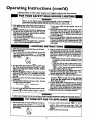
Lighting and operating instructions are located on front of the
water heater, above or to one side of the gas control valve.
_WARNING
AN ODORANT IS ADDED TO THE GAS USED
BY THIS WATER HEATER.
FOR YOUR SAFETY
IF YOU SMELL GAS:
• Do not try to light any appliance.
• Do not touch any electrical switch; do not use any phone in
your building.
• Immediately callyour gas suppiier from a neighbor's phone.
Follow the gas suppliers inm'uctions.
• If you cannot reach your gas supplier, call the fire department.
Figure 7 1
AWARNING
DO NOT force the gascontrol knob,Use onlyyour handto
pushit downto light the pilot, or to tom it to "ON" "OFF"
or "PILOT". Never usea tool suchas a lever,wrench or pliers. Do not hit or damagethe knob.A damagedknob may
result in an explosionand serious injury.If you haveproblem
turning the Imob,callthe gassupplierimmediately.
Figure 8 I
CHECK
FOR
LEAKS
Be sure to check all your gas pipes for leaks before lighting your
water heater. Use a soapy water solution, not a match or open
flame. Check the factory gas fittings after pilot is lit and gas control knob is still in _PILOT" position. Then, check the fittings
when the main burner is turned tON". Use a soapy water solution for this, too.
__NNER
DOOR
OUTER
DOOR
Figure 9 1
17
Operating
Instructions
Lighting label on the water
FOR YOUR
(cont'd)
heater as it appears above the thermostat
SAFETY
READ
BEFORE
LIGHTING
If you do not follow these instructions exactly, a fire or explosion
WARNING
I
may result caus ng property damage, persona njury or loss of life.
A. This appliance has a pilot which must be lightedby
hand.Whenlightingthe pilot,followthese Instructions
exactly.
B, BEFORELIGHTINGsmellall aroundthe appliancearea
for gas. Be sure to smell next to the floor because
somegasis heavierthenair andwill settleon thefloor.
WHATTODO IF YOUSMELLGAS
• Do not fryto lightanyappliance.
• Do not touch any electric switch; do not use any
phonein yourbuilding.
• Immediatelycall yourgas supplierfrom a neighbor's
phone.Followthegas suppUer'sinstructions,
LIGHTING
• If you cannotreach your gas supplier,call the fire
department.
C. Useonly yourhandto pushin or turnthe gas control
knob.Never usetools. If the knobwill not push In or
turnby hand,don'ttry to repair It, call a qualifiedservicetechnician.Forceor attemptedrepair may result
in a fire or explosion.
D. Do not use this applianceif any part has been under
water.Immediately call a qualifiedservicetechnician
to inspecttheapplianceandto replaceanypart of the
controlsystemand any gas controlwhich has been
under water.
INSTRUCTIONS
1. STOP!ReadthesafetyInformationaboveon this label.
2, Removeouterdoor.
3. Set the thermostat to lowest settinLby turning the
watertemperaturedial clockwise,(( "_)to itslowest
temperaturesetting(witharrowon dial)as shown.DO
9. Push in control knob all the way and hold down.
Immediatelylightthe pilot with a match.Continueto
hold control knob in for aboutone (1) minute after
the pilot is lit. Releaseknobend it will pop back up.
Pilotshould remainlit. If it goes out, repeat steps 3
through8.
• Ifknob does not pop up when released,stop and
immediatelycall your service technicianor gas
supplier,
• If the pilot will not stay lit after several tries,
NOT FORCE,
4. Turn gas controlknobclockwise_
to "OFF" position. Knob cannotbe turned from "PILOT" to "OFF"
unlessknob Is depressedslightly.DO NOT FORCE.
(Figure6, page17)
5. Wait five (5) minutesto clear out any gas. If you then
smell gas, STOPI Follow"B" in the safety information
above on this label. If you don't smell gas, go to the
nextstep.
6. Remove(or open) inner door locatedbelow the gas
control unit.
7. Find pllot-loitowmetaltube from gascontrol.The pilot
Is locatedIn frontof the burner
PILOT BURNER
._
depress_
_ and turnthe gas controlknob clockwisetechnician
=;
V
to "OFF" and sell yourservice
or gassupplier.(Figure6, page17)
10. Replace(or close) inner door. Replaceouterdoor if
door does not cover gas controlon/offknob or temperatureadustmentknob. (Figure9, page17)
11. At arms engthaway,turn gas controlknobcounterclockwise(_
to the full "ON" position. Warning
do not use gas control knob to regulate gas
flow. (Figure8, page 17)
12. At arms lengthaway,set the thermostatto desired
setting. The mark ( • ) indicativeof approximate
120°F is preferred starting point. Some local laws
may requirea lowerstartingpoint. If hotterwater is
desired,see instructionmanualand"warning"below.
13,Replacetheouterdoorif not replacedin step 10.
THERMOCOUPLE
8. Ifyou don'tsmellgas,turnknobon gascontrolcounter
dockwise_@ to "PILOT" position.(Figure7, page 17)
WARNING
Hotter water Increasesthe risk of scald injury. Before changingtemperature setting see instructionmanual.
TO TURN
OFF
GAS TO APPLIANCE
2. Turn gas controlknob clockwise !_,;
1. Set the thermostat to lowest setting by turning the
water temperaturedial clockwise(F"_) to its lowest
temperaturesetting(witharrowon dial)as shown.DO
to "OFF"
position. Knob cannot be turned from "PILOT" to
"OFF" unlessknob is depressedslightly. OO NOT
FORCE,
3. Replaceouterdoor(if removed),
NOT FORCE,
]8
Operating
Temperature
Instructions
(cont'd)
Regulation
Due to the nature of the typical gas water heater, the water tem_oeratute [rt certain situations may vary up to 30°F higher or
wer at the point of use such as, bathtubs, showers, sink, etc.
Turn the water temperature dial dockwise (_'_)
to decrease
the temperature, or counterclockwise (_-"_)
to increase the
temperature.
This means that when the temperature ad)ustment dial is set at
the mark approximating 120 ° F, the actual water temperature at
any hot water tap could be as high as 150°F or as low as 90°E
Any water heater's intended purpose is to heat water. Hot water
is needed for cleaning (bodies, dishes, clothing). Hot water will
present a scald hazard. Depending on the time element, and the
people involved (normaladults,
children,
toddlers,
elderly,
infirm, etc.) scalding may occur at different temperatures.
AWARNING
HOTTER WATER CAN SCAI._. Wa_" hoaters areintendedto
i_d...ucehot water..Water heatedto a temperature whichwill
satisfyclotheswashm&dishwashing,and other sanitizingneeds
canscaldand permanentlyinjureyouuponcontact.Some pe_
pieare more likelyto be permanentlyinjuredbyhot waterthan
othe_ Theseincludethe elder_,children,the infirm,or physicallylrn_€
handicapped. Ifanyoneusinghot water in yourhome
fitsintoone ofthesegroupsor ifthere isa localcodeor statelaw
requiringa certaintemperaturewaterat the hotwater tap,then
roumusttakespecialprecautions.
In additionto usingthe lowest
3os_le temperaturesettingthat satisfiesyourhot water needs,
i meanssuchasa mixingvalve,shouldbe usedat the hot water
tap_usedby these peopleor at the water heater.Mixingvalves
areavailableat plumbingsupplyor hardwarestores.Followmanufacturers instructionsfor installationof the valves.Before
changing the factory setting on the thermostat, read the
'rl'emperatureRegulation"sectionin this manual.
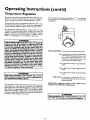
PILOT LIGHTING-Set
A-Is
here before attempting to light pilot.
a thermostat
setting of approximately
120°F, which will supply hot water at the
most economical
temperatures.
The
temperature
adjustment
knob Can be
turned lower than 120°F if desired.
A-Is a thermostat setting of approximately
130°E
B-Is a thermostat setting of approximately
140°E
C-Is a thermostat setting of approXimately
150°E
AWARNING
Never aUowsmallchildren_o usea hot water top, or to drasv_
their own bath water. Never leavea childor handicappedpersonunattendedin a bathtub or shower.
I
VERY
HOT-Is
a thermostat
setting of 160°E It is
recommended
that the dial be set lower
whenever possible.
NOTE: Water temperature range of 120°--140°F
mended by most dishwasher manufacturers.
The thermostat of this water heater has been factory set at its
lowest position, to reduce the risk of scald injury. It is adjustable
and must be reset to the desired temperature setting. The mark
(A) indicative of approximately 120°F is the preferred starting
point. Some states have a requirement for a lower setting. If you
need hotter water, follow directions for temperature adjustment,
but beware of the warnings in this section.
recom-
AWARNING
Shouldoverheating occur or the gassupplyfail to shut off,
torn OFF' the manualgas€ontro valveto the applance.
19J
Service and Adjustment
Tank (Sediment)
Cleaning
Burner
Sediment build-up
on the tank bottom may create varying
amounts of noise, and if left in the tank will cause premature
tank failure. In some water areas, you may not be able to drain
all sediment deposits by simply draining the tank. In these cases
Mag Erad (part no. 23600) can be used to help remove the sediment deposits. This may be ordered from the Sears Service
Center. For ordering, refer to the _Repair Parts" section.
J
Inspection
AWARNING
7
Do not usethis appr_nceif anypart of it hasbeen underwater.]
Immediately call a Sears Service Technicianto respecttheJ
applianceand to.replace the gascontrol or any part of the I
burnersystemwhichhasbeenunderwater.
|
At least once a _,ear a visual inspection should be made of the
main burner annpilot burner. The drawing is for your reference.
Venting System Inspection
You should check for sooting
impair proper combustion.
At least once a year a visual inspection should be made of the
venting system. You should look for:
Obstructions
which could cause improper venting. The combustion and ventilation air flow must not be obstructed.
Damage or deterioration
which could cause improper venting or |eakage of combustion products.
• Rusted flakes around top of water heater.
which
is not normal
and will
&WARNING
Chemical vapor corrosion of the flue and vent system may
occur if air fur combustion contains certain chemical vapors.
Spray can propellants, cleaning solvents, refrigerator and air
conditioner refriger-_ts,
swimming poo! chemicals, calcium
and sodium ch oride, waxes, bleach, and processchemicals an
typical compounds which are potentially corrosive.
I
•
AWARNING
Soot build-up indlcatesa problem that requires correction
beforefurther use.Turn "OFF" gasto water heater and leave
"OFF" until repairsare made, becausefailure to con_ct the
causeof the sooting can resultin a fire or explosioncausing
DEATH,SERIOUSBODILYINJURY,OR PROPERTYDAMAGE.
_WARNING
Obstructed or deteriorated vent systems may present a serious
heaJthrisk or asphyxiation.
Burner Cleaning
In the event your burner
instructions:
&,.WARNING
I
Be sure the vent piping ts properly connected to prevent
e_.
o.fdangerous flue gasseswhich could cause deadly
asphyxia_on.
•
needs cleaning,
use the following
If inspection of the burner shows that cleaning is reouired, turn
the gas control knob clockwise (_x)
to the "OF1 _" position,
depressing slightly.
NOTE: The knob cannot be turned from "PILOT" m "OFF"
unless knob is depressed slightS. DO NOT FORCE.
_,WARNING
If after inspection of the vent system you found sooting or
deterioration, something is wrong. Call the local gas utility to I
correct the problem and clean or replace the flue and venting I
[ before resum ng opera, on of the water heater.
[
Loose deposits on or around the burner can be removed by carefully using the hose of a vacuum cleaner inserted through the
access door of the water heater. If the burner needs to be removed
for additional cleaning, call the Sears Service Center to remove
and clean the burner and correct the problem that required the
burner to be cleaned.
20
Service
and Adjustment
L.P.Gas Control Valve & Burner
Assembly Replacement
Information
(cont'd)
Temperature-Pressure
Valve Operation
Relief
The temperature-pressure relief valve must be manually operated
at least once
a year.
AWARNING
PROPANE (L.R) GAS CONTROL VALVE AND BURNER
ASSEMBLYREPLACEMENT INFORMATION.
TEMPERATURE-PRESSURE
RELIEF VALVE
/
For Propane(LR) Gas ModelsOnlF.
Yourwater heater isequippedwith a Propane(L.R) gascontrol valveand a main burnerassemblywith left handthreads
for the followingfittingsand their connections.
The connection between the manifold and the gas
control valve (A to B) are left hand threads.
The connection between the main burner orifice
and the manifold (C to D) are left hand threads.
DISCHARGE
PIPE
For ordering these replacement parts, please refer to
the "Repair Parts" section of this manual.
Failure to install and maintain a new properly listed temperature-pressure relief valve will release the manufacturer from any
claim which might result from excessive temperature or pressure.
AWARNING
If the temperature-pressure relief valve on the appliance
weepsor dischargesperiodically, this may be due to thermal
expansion. Your water heater may have a check valve
installed in the water line or a water meter with a check
valve. Consultthe Sears Service Center for further informadon, Do not plugthe temperature-pressure reliefvalve.
AWARNING
When thecldng the temperatur_%o,
ressurerelief valveopera1don,rnake sure that (I) no one m in frant of or aroundthe
out_ of the temperature-pressure rid'mrvelve dischargeline,
Draining
_
The water heater should be drained if being shut down during
freezing temperatures. Also periodic draining and cleaning of
sediment from the tank may be necessary.
(2)thatthe wa_r manuelly
disd_
wmnot cameany
p_w_ d_m_ _u_. thewa_ mwbeex_m_yho_
If after manually operating the valve, it fails to completely
reset and continuesto release _
immesli_ely closethe
€old water inlet to the water heater, follow the draining
instructions, and replace the temperature-pressure relief
vahmwith a newone.
Turn the gas control knob to the "OFF" position.
CLOSE the cold water inlet valve to the water heater.
• OPEN a nearby hot water faucet and leave open to allow for
draining.
Connect a hose to the drain valve and terminate to an adequate drain,
OPEN the water heater drain valve to allow for tank
draining.
NOTE: If the water heater is gohag to be shut down and
drained for an extended period, the drain valve should be
left open with hose connected allowing water to terminate
to an adequate drain.
Close thedrain valve.
Follow instructions in the "FitlingThe
Water Heater".
s_ction.
• Follow the lighting instructions in the "Lighting" section to
restart the water heater.
21
Service and Adjustment
Drain Valve Washer
Replacement
NOT_ For replacem_t,
use a _" x '_," • _" thick washer
available at your n_rest hardware store_ For ordering replacement washers, re_ to the "Parts Order List" sec_on.
•
•
Turn "OFF" gas supply to water heater.
Follow "Draining" instructions.
Turning counter clockwise, remove the hex cap below the
screw handle.
•
Remove the washer and put the new one in place.
Screw the handle and cap assembly back into the drain valve
and tetighten using a wrench. DO NOT OVER TIGHTEN.
Follow instructions
in the _Filling The Water Heater"
section.
Check for leaks.
Follow the lighting instructions in the "Lighting " section to
restart the water heater,
_
HANDLE
AND CAP
ASSEMBLY
"" WASHER
Housekeeping
Vacuum around base of water heater for dust, dirt, and lint on a
basis.
&,WARNING
INSTALLED
IN SUITABLE AREA: To insure sufficient ventilation and combustion air supply, proper
clearances from the water heater must be maintained. See "Facts to Consider About the Location"
section. Combustible materials such as clothing,
cleaning materials, or flammable liquids, etc. must
not be placed against or adjacent to the water
heater which can cause a fire.
Service
Before calling for repair service, read the Start Up Conditions
and Operational
Conditions
found in the Troubleshooting
Guide of this manual.
If a condition persists or you are uncertain about the operation
of the water heater, let a qualified person check it out.
Contact SEARS Repair Services at 1-800-4-MY-HOME
(1-800-469-4665).
22
(cont'd)
Troubleshooting
Guide
Start Up Conditions
THERMAL
EXPANSION
HOT
COLD WATER
HEATER
EXPANSION
TANK
(i)
!
PRESSUREGAUGE
WATER
SHUTOFF
RECOMMENDED INSTALLATIOH
(VEmlCALMOUN'nNG).
It is recommended that any devices installed which could create a
dosed system have a by-pass and/or the system have an expansion tank to relieve the pressure built by thermal expansion.
Thermal expansion tanks are available from Sears stores and
through the Sears Service Centers. Contact the local plumbing
inspector, water supplier and/or the Sears Service Center for
assistance in controlling these situations.
WATER HEATER
COLD WATER
INLET FITTING
HOT
FLOOR, CEILING
jots_, ETC.
COLD
Expansion Tank Specifications
Model
Number
153.331020
PRESSURE
I_I_UCIIqG
VALVEWITH
BY-PASS
The water within the water heater tank expands as it is heated and
increases the pressure of the water system. If the relieving point of
the water heater s temperature-pressure relief valve is reached, the
valve will relieve the excess pressure. The te.mperaturc-pr_anre
relief valve is not intendedfor the constant relief of thermal
expansion, This is an unacceptable condition and must he corrected.
Thermal
O)
COLD WATER
INLET FITTING
Water supflly systems may, because of such events as high line
pressure, trequent cut-offs, the effects of water hammer among
others, have installed devices such as pressure reducing valves,
check valves, back flowpreventers, etc...to control these types of
problems. When these devices are not equipped with an internal
by-pass, and no other measures are taken, the devices cause the
water system to be closed. As water is heated, it expands (thermal expansion) and closed systems do not allow for the expansion of heated water.
Dimensions in Inches Pipe Fitting
On Tank
Diameter
Length
8 inches 12_ inches
_" Male
Tank Capacity
In Gallons
I
2
5
153.331050
Expansion
11 inches 14_ inches
O)
PRESSURE
REDUCING
VALVE WITH
_" Male
Tank Sizing Chart
Inlet*
Water
Pressure
Expansion
Tank
40psi
Capacity
Needed
60psi
70psi
180psi
5092
•
INLET COLD
WATER
SHUTOFF
PRESSUREGAUGE
AL_TE
3_0Water
RECOI,IHENDEO
INSTALLATION
(HORIZONTAL MOUNTING)
Heater Capacity (Gallons)
2
2
2
2
2
2
2
2
5
5
5
5
5
5
5
5
2
5
5
5
5
*Highest recorded inlet water pressure
regulated water pressure.
in a 24 hour
period
STRANGE
SOUNDS
Possible noises due to expansion and contraction of some metal
parts during periods of hcat-up and cool-down do not represent
harmful or dangerous conditions.
or
NOTE:
Expansion
tanks are pre-charged
with a 40 psi air
charge. If the inlet water pressure is higher than 40 psi, the
expansion tanks air pressure must be adjusted to match that
pressure, but must not be higher than 80 psi.
Condensation causes sizzling and popping with the burner area
during heati n_ and coolin_ periods and should be considered
normal. See Condensation section.
23
Troubleshooting
Start Up Conditions
Guide (cont'd)
(cont'd)
CONDENSATION
SMOKE/ODOR
Whenever the water heater is filled with cold water, a certain
amount of condensation will form while the burner is on. A
water heater may appear to be leakingwhen in fact the water is
condensation. This usually happens when:
• When a new water heater is filled with cold water for the
first time.
• When gas burns and water vapor is produced in water
heaters, particularly high efficiency models where flue temperatures are lower.
• When you use lasge amounts of hot water in a short time
and the refill water is very cold.
It is not uncommon to experience a small amount of smoke and
odor during the initial start-up. This is due to burning off of oil
from metal parts, and will disappear in a short while. -
Operational
SMELLY
Conditions
WATER
In each glasslined water heater there is installed at least one
anode rod (see parts section) for corrosion protection
of the
tank. Certain water conditions will cause a reaction between this
Moisture from the products of combustion condense on the
cooler tank surfaces and form drops of water which may ,fall
onto the burner or other hot surfaces to produce a "sizzling' or
"frying" noise.
rod and the water. The most common complaint associated with
the anode rod is one ofa rurren egg smell". This odor is derived
from hydrogen sulfide gas dissolved in the water. The smell is
the result of four factors which must all be present for the odor
to develop:
Excessive condensation can cause pilot outage due to water running down the flue tube onto the main burner and putting out
the pilot.
a. a concentration
ofsulfare in the supply warer.
b. little or no dissolved oxygen in the water.
c. a sulfate reducing bacteria within the water heater. (This
harmless bacteria is non-toxic to humans.)
d. an excess of active hydrogen in the tank. This is caused by
the corrosion protective action of the anode.
Because of the suddenness and amount of water, condensation
water may be diagnosed as a "tank leak". After the water in the
tank warms up (about 1-2 hours), the condition should
disappear.
Smelly water may be eliminated or reduced in some water heater
models by replacing the anode(s) with one of less active material,
and then chlorinating
the water heater tank and all hot water
lines. Contact Sears Service for further information
concerning
anAnode
Replacement Kit #9001453
and this Chlorination
Treatment.
Do not assume the water hearer is leaking until there has been
enough time for the water in the tank to warm up.
An undersized water heater will cause more Condensation. The
water heater must be sized properly to meet the family's
demands for hot water including dishwashers, washing machines
and shower heads.
If the smelly water persists after the anode replacement and chlorination treatment, we can only suggest that continuous chlorination and filtering conditioning equipment be considered to
eliminate the water problem.
Excessive condensation may be noticed during the winter and
early spring months when incoming water temperatures are at
their lowest.
Do not remove the anode leaving the tank unprotected. By
doing so, all warranty on the water heater tank is voided.
Good venting is essential for a gas fired water heater to operate
properly as well as to carry away products of combustion and
water vapor.
"AIR"
&WARNING
HOTTER WATER CAN SCALD:Water heatersare intendedto
producebet watt. Water _
to a temperature.whichwill
satisfyclotheswashing,dishwashm&end other senitizmgneeds
canscaldand permanentlyinjureyouupon contact.Somepeople are more Ik_elyto be permanen..tiy,
injured byhot water than
otbe_ Theseincludethe elderly,chtklren,the inlirm,or physical.
lylmentally handicapped, If anyone using hot water in your home
fits into one of these groups or ifthere is a local €ode er stato law
requiringa certain temperature water at the bet water tap, then
you must take special precautions.In addition to usingthe lowest
possible
temperaturesettingthat satisfies yourhot water needs,
a meanssuchasa mixingvalve,shouldbe usedat the hot water
tapsusedbythesepeopleor at the water heater.Mixingvalves
are availableat plumbingsupplyor hardwarestoregFollowman.
ofacturers instructionsfor installationof she valves.Before
changingthe factory setting on the thermostat, read the
'q'emperaUaeRegelation"sectionin shismanual.
IN HOT WATER
FAUCETS
AWARNING
HYDROGEN GAS: Hydrogengas can be producedin a hot
water systemthat hasnot been usedfor a longperiod of time
(generally two weeks or more). Hydrogen gas is extremely
flammable end explosive.To preventthe possibilityof injury
under theseconditions,we recommendthe hot wa_r faucet
be openedfor severalminutesat the kitchensinkbeforeany
electricalapplianceswhichare connectedto the hot water system are used (suchas a dishwasheror washingmachine).If
hydrogengas is present, there will probably be an unusual
soundsimilarto air escapingthroughthe pipeas the hot water
faucet is opened.There must be no smoking or open flame
near the faucetat the time it isopen.
I
24
Troubleshooting
HIGH
TEMPERATURE
SHUT
Guide (cont'd)
OFF SYSTEM
AWARNING
Due to the nature of the typical gas water heater, the
Iwater temperature in certain situations may be hotter
than the thermostat $etUng.
Short, frequent draws of hot water - especiallywith very
cold incoming water, can shockthe thermostat into br_f
operation resulting in hotter and hotter layers of water
closerto the top of the tank.
Changes in hot water usage patterns or raisingthe temperature differential between the cut-on of the thermostat and the cold water temperature will usuallyeliminate
the problem.
This water heater is equipped with an automatic gas shut offsystern. The high temperature shut off is built into the gas control
waive. This system shuts off the gas supply to the water heater
burners when high water temperatures are present. It is nonresettable. If the high temperature shut offactivates, the gas contro[ valve must be replaced. If this were to occur, turn "OFF" the
entire gas supply to the water heater• Contact the Sears Service
Center.
I
AWARNING
Should overheating occur or the gas supplyfail to shut off,
turn "OFF" the manual gascontrol valve to the appliance.
NOT
i
ENOUGH
OR NO
HOT
WATER
Check the pilot flame. It may have gone out. All models have
Check
the manual
be sure the
it ispilot.
open.
an opening
behind gas
the shut
outeroffvalve
door fortoviewing
If the pilot is not lit, follow the Lighting" instructions in this
manual or located above tEe gas control valve on the water
heater to relight the pilot. If the water was extremely hot and is
now cold, the high limit safety temperature shut off may have
put out the burner and pilot. If the high temperature shut off
activates, thegns controlvalve must be replaced. Contact the
Sears Service Center.
The temperature adjustment dial may be set too low. See the
"Tempetatuse Regulation section.
The gas
gas rX_ntrolknob
company can must
checkbethe
gas input
see if it
is correct.
_i The
turned
to theto"ON"
position.
An underfired water heater will not heat water as quickly.
Look for leaking or open hot water faucets. Make sure all are
dosed.
• The cold water inlet temperature may be colder during the
winter months. It will take longer to heat the water and seem
like less hot water.
• If you cannot find what is wrong, call the Sears Service
Center.
WATER
IS TOO
HOT
• The temperature adjustment dial may be set too high, See the
Temperature Adjustment
section,
NOTE: A period of time is necessary after an adjustment
has been made for the water temperature to reach the new
temperxture
setting.
• If lower temperature settlngs will not lower the water temperature, call the Sears Service Center,
:.25
Troubleshooting
Guide
(cont'd)
Leakage Checkpoints
Use this guide to check a "Leaking" water heater. Many suspected "Leakers" are not leaking tanks. ®hen the source of the water
can be found and corrected.
ACAUTION
[
Reed this manual first. Then before checking the water I
heater make sure the gas supply has been turned [
"OFF", and never turn the gas "ON" before the tank isI
completely full of water.
[
If you are not thoroughly familiar with your local gas codes your
water heater, and safety practices, contact the
Center to check the water heater.
J
A CAUTION.
]
Never use this water heater unlessit is completely fllledJ
with water. To prevent damage to the tank, the tank]
must be filled with water. Water must flow from the hot /
water faucet before turning "ON" gas to the water I
heater.
J
Water at the draft hood, is water vapor which has
condensed our of the combustion products. This is caused
by a problem in the vent. Contact the Sears Service Center
Q
*Condensation may be seen on pipes in humid weather or
pipe connections may be leaking.
O'The
primary anode rod fitting may be leaking.
Small amounts of water from temperature-pressure
relief
valve may be due to thermal expansion or high water
pressure in your area.
*The temperature-pressure
the tank fitting.
relief valve may be leaking at
Water
slighdy.from a drain valve may be due to the valve opened
O'The
drain valve may be leaking at the tank fitting.
Combustion
can
condense on products
the cooler contain
surfaces water
of thevapor
tank. which
Droplets
form and drip into the fire or run on the floor. This is
common at the time of startup after installation and when
incoming water is cold.
®
®
®
Water in the water heater bottom or on the floor may be
from condensation, loose connections, or the relief valve.
DO NOT replace the water heater until a full inspection
of all possible water sources is made and necessary
corrective steps taken. Leakage from other appliances,
water lines, or ground seepage should also be checked.
NOTE: To check where threaded portion enters tank,
insert cotton swab between jacket opening and fitting.
If cotton is wet, follow "Draining" instructions in the
"Service and Adjustment" section and then remove
fitting. Put pipe dope or teflon tape on the threads
and replace. Then follow "Filling the Water Heater"
instructions in the "Installation Instructions" section.
®
26
Notes
Notes
28
Notes
Parts Order
List
POWER MISER TM 9 GAS WATER HEATERS
MODEL NUMBERS:
153.337113
153.337162
153.337213
153.337262
153.337362
153.337413
50
50
40
40
30
40
Gal.
Gal.
Gal.
Gal.
Gal.
Gal.
Short High Aldtude
Short
Short High Altitude
Short
High Altitude
....
__--_---.-_--_------.--.--__.__]
16
17
0
14 0
12
3O
Parts Order List (cont'd)
POWER
MISER
MODEL
NUMBEBH:
153.337113
153.337162
153.337213
153.337262
153.337362
153.337413
TM
50
50
40
40
30
40
9 GAS WATER HEATERS
Gal.
Gal.
Gal.
Gal.
Gal.
Gal.
Short High Altitude
Short
Short High Altitude
Short
High Altitude
Model Numbers
I
KEY
NO.
153.337113[
153.337162
153.337213
153.337262
153.337362
153.337413
9000071
9000071
90O0071
9001829
90O0071
9001829
9000071
90O0734
9O00734
9O00734
0270118
0270118
0270118
0270118
0270118
9OO0254
9000254
9000254
9000254
9000254
I
PART N! JMBERS
PART DESCRIPTION
1
2
3
4
5
Temperature-Pressure Relief Valve
Primary Anode Rod
Model Rating Plate _"
Drain Valve
Drain Valve Washer
(_7u"x ly.,, x W' thick)**
9000071
9OOO734
0270118
9000254
90O1584
9001584
9001584
90O1584
9001584
9001584
6
7
8
Thermocouple*
Pilot Tubin[_ w/Fittin[_s
Burner Orifice
42-33900
42-33900
42-33900
42-33900
42-3390O
42-33900
9000278
9000278
9000278
0230141
#36(HA)
0230120
#33
9000278
0230120
#33
9000278
0230120
#33
0230141
#36(HA)
9
10
11
12
13
Manifold
Pilot
Manifold Cover
Inner Door
Gas Control Valve
9002619
9000284
9O02619
9000284
0230141
#36(HA)
9002617
9000358
9000281
14
15
Temperature Adjustment Knob
Burner
16
17
18
9000278
9002617
9O02613
9002615
9000284
9000284
9000284
9000358
9000281
9000358
9000358
9000358
9000284
9000358
9000281
9000281
9000281
9000281
F145-1278
F145-1278
F145-1278
F145-1278
F145-1278
F145-1278
F145-1280
F145-1280
F145-1280
F145-1280
F145-1280
F145-1280
9002411
9002411
9002411
9002411
9002411
9002411
Dip Tube
Flue Baffle
Draft Hood
9002067
9002067
9001981
9001981
9001698
9001698
90O2495
9002495
9002281
9002281
9002490
9000516
9000273
9000273
9000273
9000273
19
#
Restrictor Ring
Manual
90012O8
9001208
9000275
9000275
0002915840
9O00273
90O0275
9000273
9000275
#
Mag-Erad
23600
Now that you have purchased your Gas Water Heater, should a need ever exist for repair pasts or service, simply contact any SEARS Service
Center or call 1-800-4-MY-HOME
(1-800-469-4663).
Be sure to provide pertinent facts when you call or visit.
All parts listed may be ordered from any SEARS Service Center, most SEARS stores and by calling 1-800-366-PART (1-800-366-7247).
If the
parts you need are not stocked locally, your order will be electronically transmitted to a SEARS Repair Parts Distribution Center for handling.
The model number
WHEN
of your Gas Water Heater will be found on the model rating plate located near the gas control valve.
ORDERING
REPAIR PARTS, ALWAYS GIVE THE
MODEL NUMBER
PART DESCRIPTION
PART NUMBER
NAME OF ITEM
FOLLOWING
THIS IS A REPAIR PARTS LIST, NOT A PACKING LIST.
31
INFORMATION:
Parts Order
List (cont'd)
POWER MISER TM 9 GAS WATER HEATERS
MODEL NUMBERS:
153.337462
4O Gal.
153.337513
50 Gal. High Altitude
153.337562
50 Gal.
153.337613
65 Gal. High. Altitude
2
12
32
Parts Order List (cont'd)
POWER
MODEL
MISER TM 9 GAS WATER HEATERS
NUMBERS:
153.337462
153.337513
153.337562
153.337613
40
50
50
65
Gal.
Gal. High Altitude
Gal.
Gal. High Altitnde
Model Numbers
153.337462
153.337513
Temperature-Pressure Relief Valve
Primar_ Anode Rod
Model Rating Plate 1"
Drain Valve
Drain Valve Washer
(1_,, x W." x W' thick)**
9000071
9000734
0270118
9000254
9000071
9000071
9000071
9000734
9000734
9000734
0270118
0270118
0270118
9000254
9000254
9000254
9001584
6
7
8
Thermocouple*
Pilot Tubin/_w/Fittings
Burner Orifice
9001584
42-33900
9001584
42-33900
9001584
42-33900
9000278
9000278
9000278
9
10
11
12
13
Manifold
Pilot
Manifold Cover
Inner Doot
Gas Control Valve
42-33900
9000278
0230120
#33
9002615
9000284
9000358
9000281
F145-1278
0230141
#36(HA)
9002617
0230120
#33
9002617
0230141
#36(HA)
9002619
9000284
9000284
9000284
9000358
9000358
9000281
9000281
9000358
9000281
F145-1278
F145-1278
F145-1278
F145-1280
9002411
F145-1280
F145-1280
F145-1280
KEY
NO. I
1
2
3
4
5
PART DESCRIPTION
153.337562
153.337613
PART NUMBERS
14
15
Temperature Adjustment Knob
Burner
9002411
9002411
9002411
16
17
18
Dip Tube
Flue Baffle
Draft Hood
9001698
9000516
9000273
9001698
9001698
9001982
9000298
9002496
9000419
9000273
9000273
9000273
19
#
Restrictor Ring
Manual
9000275
9000275
9000275
0 002915840
9000275
#
Mag-Erad
23600
Now that you have purchased your Gas Water Heater, should a need ever exist for repair parts or service, simply contact any SEARS Service
Center or call 1-800-4-MY-HOME
(1-800-469-4663).
Be sure to provide pertinent facts when you call or visit.
All parts listed may be ordered from any SEARS Service Center, most SEARS stores and by calling 1-800-366-PART (1-800-366-7247).
If the
parts you need are not stocked locally, your order will be electtonica!.ly transmitted to a SEARS Repair Parts Disttibudon Center for handling.
The model number
WHEN
of your Gas Water Heater will be found on the model rating plate located near the gas control valve.
ORDERING
REPAIR PARTS, ALWAYS GIVE THE
MODEL NUMBER
PART DESCRIPTION
PART NUMBER
NAME OF ITEM
FOLLOWING
THIS IS A REPAIR PARTS IAST, NOT A PACKING LIST.
33
INFORMATION:
Parts Order
List (cont'd)
POWER MISER TM 9 GAS WATER HEATERS
MODEL NUMBERS:
153.337662
65 Gal.
153.337762
153.337862
153.337960
50 Gal. High Recovery
65 Gal. High R_covery
40 Gal. (LP.)
2
34
Parts Order
POWER
MISER
TM
List (cont'd)
9 GAS WATER HEATERS
MODEL NUMBERS:
153.337662
65 Gal.
153.337762
50 Gal. High Recovery
153.337862
65 Gal. High Rramvery
153.337960
40 Gal. (LP.)
Model Numb_s
KEY
NO.
1
153.337662
153.337762
9000071
9000071
9000071
9000071
9000734
0270118
9000734
9000254
9000254
PART DESCRIPTION
Temperature-Pressure
153.337960
PART N'JMBERS
Relief Valve
2
Primary Anode Rod
9000734
3
4
Model Rating Plate t
Drain Valve
0270118
9000734
0270118
9000254
9000254
5
Drain Valve Washer
0270118
(_7/_"x u/." x *,_"thick)**
9001584
9001584
9001584
9001584
6
Thermocouple*
42-33900
42-33900
42-33900
42-33900
7
8
9000278
9000278
9000278
9000278
0230120
#33
0230124
#30
0230124
#30
9
Pilot Tubin_ w/Fittin_
Burner Orifice
(Drill Size)
Manifold
9002619
9002617
9002619
0230223
#49
9002616
10
Pilot
9000284
9000284
9000284
9000286
11
Manifold
9000358
12
Inner Door
9000358
9000281
9000358
9000281
9000358
9000281
13
Gas Control
F145-1278
F145-1280
F145-1278
F145-1278
F145-1279
F145-1280
F145-1280
F145-1280
Cover
9000281
Valve
14TomperaturoAdiustmont
Knob
Note "A':
153.337862
15
Burner
9002411
9002411
9002411
9002651
16
17
Dip Tube
Flue BaiZe
9001982
9001698
9001982
9001698
9000419
9000371
9000299
9000516
18
Draft Hood
9000273
9000274
9000274
9000273
19
#
Restrictor Ring
Manual
9000275
9000297
9000297
9000275
#
Mag-Erad
0002915840
23600
For Propane (L.P.) model(s) this part has left hand threads.
* These parts arealso availableat most Sears retail stores.
**Also availableat most hardware stores.
tReplaced only on return of damaged plate.
# Not Illustrated
Now that you have purchased your Gas Water Hearer, should a need ever exist for repair parts or service, simply contact any SEARS Service
Center or call 1-800-4-MY-HOME (1-800-469-4663). Be sure to provide pertinent facts when you call or visit.
All parts listed may be orderedfrom any SEARS Service Center, most SEARS stores and by calling 1-800-366-PART (1-800-366-7247). If the
parts you need are not stocked locally, your orderwill be electronically transmitted to a SEARS RepairParts Distribution Center for handling.
The model number of your Gas Water Heater wilt be found on the model rating plate located near the gas control valve,
WHEN ORDERING REPAIR PARTS, ALWAYSGIVE THE FOLLOWING INFORMATION:
MODEL NUMBER
PART DESCRIPTION
PART NUMBER
NAME OF ITEM
THIS IS A REPAIRPARTSLIST, NOT A PACKING LIST.
35
Warranty
a. Adjusting thermostat.
b. Lightingpilot.
c. Leaksin pipesor fittings.
d. Improper venting
e, Condensation
About Your Warranty
THE PRICE OF YOUR WATER HEATER DOES NOT INCLUDE
A FREE CHECKUP SERVICE CALL.On Water HeaterInstallations
ArrangedBy Sears,Searswarrantsthe installation.
ON INSTALLATIONS NOT MADE BY SEARS AUTHORIZED
CONTRACTORS:
1. YourSearswarranty appliesto the product only.
2. Searsdoes not warrant the installation.
3. A charge will be made on service calls due to poor or incomplete
installation.These include:
This manual is in non-technical language.It may help you ,avoid the
cost of a needlessservicecall. Many servicecalls really arcut needed.
Such aswhen:
1. The gas is turned _OFF".
2. The pilot is out.
3. A gas orwater leak is due to loose pipe orconnections.
FULL ONE YEAR WARRANTY ON WATERHEATER
Forone year from the date of purchase, when your Sears Kenmore water heater is installed and operated in a single-family residence in
accordance with the instructions in this manual, Sears will:
1. Repair defects in material or workmanship in this water heater, free of charge.
2. Furnish and install a new current model water heater of equal capacity and quality, free of charge, ifa leak occurs in the rank.
LIMITED WARR/kN'TY ON TANKSTHAT LEAK
After one year and thmugh 9 years from the date of purchase for water heaters used in a single-family residence, ifa leak occurs in the
tank, Sears will famish a new current model water heater of equal capacity and quality. Yo_xwill be charged for any installation.
LIMITED WARRANTY ON PARTS
After one year and through 9 years from the date of purchase, when your Sears Kenmore water heater is used in a single-family residence
and is installed and operated in accordance with the information in this manual, if a part fails due to a materials or workmanship, Sears
will furnish a replacement free of charge. You will be charged for labor.
If the water heater is subjected to commercial, institutional, industrial or use in residences of two families or more, the above warranty
coverage for tanks that leak is effective for 2 years from the date of purchase and the above parts warranty is effective for 1 year from the
date of purchase.
To obtain warranty service, SIMPLY CALL 1-800-4MY-HOME
use in the United States."
(1-800-469-4663).
"This warranty applies only while this product is in
This warranty gives you specific legal rights and you may also have other rights which vary from state to state.
SEARS, ROEBUCK AND CO., Dept. 817 WA, HOFI_MAN ESTATES, IL 60179
Sears Installation
Warranty
In additionto any warranty extended to you on the Searsmerchandise
involved,which warranty becomeseffectivethe date the merchandiseis
installed should the workmanship of any Sears arranged installation
prove faulty within one year, Searswill, upon notice trom you, cause
such faults to be correctedat no additional,cost to you. If you want this
heater professionallyinstalled by Sears contact your SearsSalesperson.
They will arrange for prompt, quality installation,
Sears Installation
Policy
All installation laborarranged by Searsshall be performed in a neat,
workmanlike manner in accordancewith generallyacceptedtrade practices. Further, all installations shall comply with all local laws, codes
regulations and ordinances.The customer shall also be protected, during installation, by insurance relat'ng to property damage, Workers
Compensation andPublic Liability.
If you want this water heater professionallyinstalled by Sears contact
your Salesperson.They will arrange for prompt, quality installationby
Searsauthorizedcontractors.
ForIn-homemajorbrandrepairaendce
Call24 hoursa day,7 daysaweek
1-800-4-MY-HOME
0 -_0.46,_ms3)
The model numberof your water heater is foundon the model ratingplate on the front of the water heater.
I 1-99
Sears, Roebuck
and Co., Hoffman
Estates,
IL 60179
U.S.A.
0002915840-1