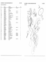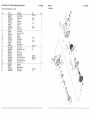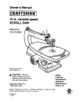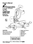
1
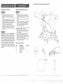
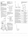
SLUDENGCOMPOUND
M_TER SAW
E82443
C@US
37J2 LISED
CAUTION:
o
o
o
o
o
o
Before using this Sliding Miter Saw,
read this manual and follow all its
Safety Rules and Operating
Instructions.
Customer
Help
Safety Instructions
Installation
Operation
Maintenance
Parts List
EspaSol
Line
1 o800o843o1682
Sears,
Roebuck
and Co., Hoffman
Part No. 137212920002
Estates,
IL 60179
USA
SECTION
PAGE
Warranty ..............................
Product Specifications
...................
Safety instructions
......................
Accessories
and Attachments
.............
Carton Contents
........................
Know Your Sliding Miter Saw ..............
Glossary
of Terms
.....
.....................................
Assembly
and Adjustments
...................................
Operation
...............................................
Maintenance
....................
i...
: .....................
Troubleshooting
guide .......................................
Parts .....................................................
EspaSol ................................................................
BEFORE USING THE SUD_NG _TER
I_l==l_l==l======_lu_==_=.J==om=j
MOTOR
Power source .........
Horsepower ..........
Speed ..............
Brake .........
_ .....
Double insulated ......
120 VAC, 60 HZ, 15 AMPS
3 HP (Max. Developed)
4300 R.RM.
Electric
Yes
GENERAL SAFETY mNSTRUCT_ONS
Safety is a combination of common sense, staying alert
and knowing how to use your sliding miter saw.
...........
...........
11
12
• ; .........
...........
...........
20
28
29
...........
30
39
i
,
TABLE DIAMETER
20-5/8"
KEEP GUARDS _NPLACE and in working order.
3.
REMOVE ADJUSTING KEYS AND WRENCHES.
Form the habit of checking to see that keys and
adjusting wrenches are removed from the tool before
turning ON.
...........
AUXILIARY FENCE EXTENSION
Yes
...
Yes
MITRE DETENT STOPS ...
0, 15, 22.5, 31.6, 45" R & L
BEVEL POSITIVE STOPS..
0, 33.9 & 45" L
CARRIAGE SYSTEM
3 Rail, ball bearing slide
BLADE SIZE ......
.....
......
.................
To avoid electrical hazards, fire hazards, or damage to
the tool, use proper circuit protection.
Your sliding mitre saw is wired at the factory for 120V
operation. Connect to a 120',/, 15 AMP time delay fuse or
circuit breaker. To avoid shock or fire, replace power cord
immediately if it is worn, cut or damaged in any way.
12"
Crystalline silica from bricks, cement and other masonry
Arsenic and chromium from chemically-treated
lumber
activities
or other
products
Your risk from these exposures varies, depending on how often you do this type of work. To reduce
your exposure to these chemicals:work
in a well ventilated area. and work with approved safety
equipment, such as those dust masks that are specially designed to filter out microscopic particles
8.
9.
.I
15. DBCONNECT TOOLS before servicing, and when
changing accessories, such as blades, bits, cutters,
and the like.
KEEP WORK AREA CLEAN. Cluttered areas and
benches invite accidents.
16. REDUCE THE RISK OF UNiNTENTiONAL STARTING.
Make sure the switch is in OFF position before
plugging in.
17. USE RECOMMENDED ACCESSORIES. Consult the
owner's manual for the recommended accessories.
The use of improper accessories may cause risk of
injury to persons.
MAKE WORKSHOP KID PROOF wilh padlocks, master
switches, or by removing starter keys.
18. NEVER STAND ON TOOL. Serious injury could occur
if the tool is tipped or if the cutting tool is unintentionally
contacted.
DON'T FORCE THE TOOL. It will do the job better
and safer at the rate for which it was designed.
19. CHECK FOR DAMAGED PARTS. Before further use of
the tool, a guard or other part that is damaged should
be carefully checked to determine that it will operate
properly and perform its intended function. Check for
alignment of moving parts, binding of moving parts,
breakage of parts, mounting, and any other conditions
that may affect its operation. A guard or other part that
is damaged should be properly repaired or replaced.
USE THE RIGHTTOOL Don't force tool or the
attachment to do a job for which it was not designed.
10. USE PROPER EXTENSION CORD. Make sure your
extension cord is in good condition. When using an
extension cord, be sure to use one heavy enough to
carry the current your product will draw. An undersized
cord will cause a drop in line voltage resulting in loss
of power and overheating. The table on page 7 shows
the correct size to use depending on cord length and
nameplate ampere rating. If in doubt, use the next
heavier gauge. The smaller the gauge number, the
heavier the cord.
20. NEVER LEAVE TOOL RUNNING UNATTENDED.
TURN THE POWER OFF. Don't leave the tool until
it comes to a complete stop.
21. DON'T OVERREACH.
balance at all times.
11. WEAR PROPER APPAREL. DO NOT wear loose
clothing, gloves, neckties, rings, bracelets, or other
jewelry which may get caught in moving parts.
Nonslip footwear is recommended. Wear protective
hair covering to contain long hair.
SAVE THESE
!i! i ! ::: :::::i:i:ii::i:!
¸¸::!:
i¸iii:!
i!: ii!i
Keep proper footing and
22. MAINTAIN TOOLS WITH CARE. Keep tools sharp
and clean for best and safest performance. Follow
instructions for lubricating and changing accessories.
23. DIRECTION OF FEED. Feed work into a blade or cutter
against the direction of rotation of the blade or culter only.
NSTRUCT ONS
3
2
ALWAYS WEAR EYE
PROTECTION. Any miter saw
can throw foreign objects into
the eyes which could cause
permanent eye damage.
ALWAYS wear Safety Goggles
(not glasses) that comply with
ANSI safety standard Z87.1. Everyday eyeglasses
have only impact-resistant lenses. ]hey ARE NOT
safety glasses. Safety Goggles are available at Sears.
NOTE: Glasses or goggles not in compliance with ANSI
2:87.1 could seriously hurt you when they break.
14. SECURE WORK. Use clamps or a vise to hold work
when practical. It's safer than using your hand and it
frees both hands to operate tool.
KEEP CHILDREN AWAY. All visitors should be kept at
a safe distance from the work area.
Lb.
,
Some dust created by power sanding, sawing, grinding, drilling, and other construction
contains chemicals
known [to the State of Califcrnia]
to cause cancer, birth defects
reproductive
harm
Some examples of these chemicals are:
e Lead from lead-based paints
®
61.6
W_ARYOUR
13. WEAR A FACE MASK OR DUST MASK.
Sawing operation produces dust.
DON'T USE IN A DANGEROUS ENVIRONMENT.
Don't use power tools in damp or wet locations, or
expose them to rain. Keep work area welt lighted.
5.
DUST COLLECTION
READ and become familiar with this entire instruction
manual. LEARN the tool's applications, limitations, and
possible hazards.
2.
.
5/8"
.............
To avoid mistakes that could cause serious injury, do not
plug the miter saw in until you have read and understood
the following:
6,
4" x 12-5/8"
4" x 8-3/4"
2-1/2" x 12-5/8"
2-1/2" x 8-3/4"
SAW
2
ARBOR SIZE ..................
NET WEIGHT
CUTTING CAPACITY
0" Mitre - 0' Bevel .....
45" Mitre - 0 r Bevel ....
0 r Mitre - 45" Bevel ....
45' Mitre - 45" Bevel ...
12.
14. KEEP HANDS out of the path of the saw blade. If the
workpiece you are cutting would cause your hand to
be within 6-1/2 inches of the saw blade, the W0rkpiece
should be clamped in place before making the cut.
24. DO NOT operate the tool if you are under the
influence of any drugs, alcohol or medication that
could affect your ability to use the tool properly.
25. WARNnNG: Dust generated from certain materials can
be injurious to your health. Always operate miter saw in
well ventilated areas and provide for proper dust removal.
15. MAKE SURE the blade and collars are clean and
properly arranged. After installing a new blade, make
sure the blade clears the table slot at the 0o and 45 °
bevel positions. Lower the blade into the table slot and
check for any contact with the base or turn table
structure. If the blade contacts the table, see the
TROUBLESHOOTING GUnDE for "depth stop
adjustment" or contact the Sears Service Center.
Broken saw parts could injure you or others.
SPEC HC SAFETY NSTRUCT ONS
FOR SUDRNG VHTER SAWS
1.
2.
3.
4.
5.
6.
7.
8.
9.
READ AND UNDERSTAND all safety instructions
and operating procedures throughout the manual.
16. ALWAYS check the blade for cracks or damage
before operation. Replace a cracked or damaged
blade immediately.
DO NOT operate the miter saw until it is completely
assembled and installed according to the instructions.
SHOULD any part of your miter saw be missing,
damaged, or fail in any way, or any electrical
component fail to perbrm properly, shut off tile switch
and remove the plug from the power supply outleL
Replace missing, damaged, or failed parts before
resuming operation.
17. USE blades recommended
19. TO KEEP the pivot nut from working its way off as you
use the saw, at least one thread of the pivot bolt must
always stick out past the nut. Always keep the nut at
least that tight.
IFYOU ARE NOT thoroughly familiar with the
operation of miter saws, obtain advice from your
supervisor, instructor, or other qualified person.
20. FAILURE TO'RGHTEN the jam nut could let the depth
stop slip and let the blade strike the saw table.
Broken saw parts could injure you or others.
NEVER CARRY the tool by the cord or the cutting
head handle. Damage to the insulation could cause
electric shock. Damage to the wire connections could
cause a fire.
21. CLEAR EVERYTHING except the workpiece and
related support devices off the table before turning
the miter saw on.
SERIOUS _NJURY could occur if the tool tips over or
you accidentally hit the cutting tool. Do not store
anything above or near the tool.
22. MAKE SURE all clamps and locks are tight and
there is no excessive play in any part.
23. ALWAYS MAKE SURE all handles are tight before
cutting, even if the table is positioned in one of the
positive stops.
AVOID nNJURY from unexpected saw movement.
Place the saw on a firm level surface where the saw
does not rock, and bolt or clamp the saw to its support.
24. MAKE SURE there are no nails or foreign objects in
•the part of the workpiece to be cut.
BEFORE MOWNG the saw, lock the miter, bevel, and
cutting head positions.
25. MAKE SURE the blade is not contacting the workpiece
before the switch is turned on.
CHOOSE the right 12" diameter blade for the
material and the type of cutting you plan to do. Never
use blades larger or smaller in diameter than
recommended.
10. USE ONLY CROSSCUTTING SAW BLADES. Do not
use blades with deep gullets as they can deflect to
the side and contact the guard.
11. USE only blade collars specified for your saw. The
recessed sides must Pace the blade ......
12. USING THE HEX BLADE WRENCH supplied, make
sure the arbor screw is firmly tightened.
13. NEVER USE the saw without the cover plate securely
in place. It keeps the arbor screw from falling out if it
accidentally loosens, and orevents the spinning blade
from cornJng off the machine.
at 4300 RPM or greater.
18. ALWAYS keep the blade guards in place.
26. ALWAYS hold the work firmly against the fence and
table. DO NOT perform any operation freehand.
.
27. DO NOTTRYTO CUT SHORT PIECES, You cannot
piopefiy _up#6!t ih6w0ikpiece
and keep yoUr
hoiGd0wn hand the required distance from the blade.
28. ALWAYST_GHTENTHE CLAMP so that the workpiece
is secured between the clamp and fence or base. No
visible gap should be present between saw and wood.
29. NEVER cut metals or masonry. Because of the
sliding action of the saw, this machine is not designed
for cutting metals. Use this miter saw to cut only wood
and woodlike products. Other materials may shatter,
bind on the blade, start fires or create othe- dangers.
30. NEVER reach around the saw blade.
SAVE THESE WNSTRUCT ONS
3"1• NEVER PULL THE SAW toward you during a cut.
The blade can suddenly climb up on Iop of the
workpiece and force itself toward you.
SMOOTH, solid movement of sliding assembly.
OTHER conditions that may affect the way the
miter saw works. If any part of the miter is
missing, bent, or broken in any way, or any
electrical parts don't work, turn the saw off and
unplug it. REPLACE damaged, missing, or failed
parts before using the saw again.
32. ALLOW the motor to come up to full speed before
starting cut.
33. KEEP the motor air slots clean and free of chips.
34. NEVER apply lubricants to the blade when it is
running.
4+3,
35. MAKE SURE the blade has come to a complete stop
before removing or securing the workpiece, changing
the workpiece angle, or changing the angle of the
blade.
44. REMOVE adjusting keys and wrenches from the tool
before turning it on.
36. NEVER use the miter saw in an area with flammable
liquids or gases.
45. TO AVOID INJURY FROM JAMS, SMPS, OR
THROWN PECES:
°
USE ONLY RECOMMENDED ACCESSORIES.
Consult this Owner's Manual for recommended
accessories. Follow the instructions that come
with the accessories. The use of improper
accessories may cause risk of injury to persons.
o
MAKE SURE the blade is sharp, undamaged,
properly aligned and free of vibration. With the
saw unplugged, push the cutting head all the way
down. Hand spin the blade and check for
clearance. Tilt the cutting head to a 45 degree
bevel and repeat the check. If the blade hits
anything, see the TROUBLESHOOTING
GUIDE
for "depth stop adjustment", or contact your
Sears Service Center.
37. NEVER use solvents to clean plastic parts. Solvents
could possibly dissolve or otherwise damage the
material.
38. ALWAYS PERFORM DRY RUNS+ Make sure the saw
is unplugged. Completely set up your saw. Pull the
blade and cutting head through the full range of motion
to check for interference. When using a clamp make
sure that your blade, saw guard or motor does not
interfere with the clamp. Correct any interference
before use.
39. PLAN HOW YOU WILL MAKE THE CUT:
°
MAKE SURE the blade is net spinning.
,
RAISE the blade.
,
SUDE the saw out above the front edge of the
workpiece before starting the saw.
PUSH the saw blade down on top of the wood and
back toward the rear of the saw to make the cut.
BEFORE
KEEP GUARDS UNPLACE, in working order, and in
proper adjustment. Maintain tools with care.
Keep the miter saw clean for best and safest
performance. Follow instructions for lubricating.
DON'T put lubricants on the blade while it's spinning,
46. PLAN HOW you will hold the workpiece from start
to finish:
+
EACH USE
40. JNSPEOTYOUR
°
MITER SAW.
°
41. D+SCONNECTTHE M_TER SAW. To avoid injury from
accidental starting, unplug the saw before changing
the setup, changing the blade, or adjusting anything.
Compare the direction of the rotation arrow on the
guard to the direction arrow on the blade. The blade
teeth should always point downward at the front of the
saw. Tighten the arbor screw. Tighten the cover plate
screw.
+
42. CHECK FOR DAMAGED PARTS° Check for:
°
PROPER alignment of moving parts
+
DAMAGED electric cords
,
BINDING of moving parts
°
BROKEN parts
+ STABLE mounting
+
FUNCTION of arm return spring and lower guard:
Push the arm all the way down, then let it rise
up until it stops by itself. Check the lower guard
to see if it closed fully. If it did not, follow the
instructions in the TROUBLESHOOTONG GUDDE.
SAVE THESE
°
°
,
°
AVOID awkward operations and hand positions
where a sudden slip could cause fingers or
hand to move into the blade.
DON'T OVERREACH. Keep good footing and
balance.
KEEP your face and body to one side of the
saw blade, out of line with a possible throwback.
NEVER CUT FREEHAND:
+ BRACE your workpiece solidly against the fence
and table top so it will not rock or twist during
the cut.
MAKE SURE there is no debris between the
workpiece and its supports.
- MAKE SURE no gaps between the workpiece,
fence and table wilt let the workpiece shift after
it is cut in two.
CUT only one workpiece at a time.
KEEP the cut off piece free to move sideways
after it is cut off. Otherwise it could get wedged
against the blade and be thrown violently•
CLEAR everything except the workpiece and
related support devices off the worktable before
turning the miter saw on.
SECURE WORK. Use clamps or a vise to help
hold the work when it is practical.
NSTRUCT ONS
5
47. USEEXTRACAUTION
withlarge,verysmallor
awkwardworkpieces:
USEextrasupports(tables,sawhorses,blocks,
etc.)foranyworkpieces
largeenoughtotip
whennothelddownto thetabletop.
o NEVERuseanotherpersonas a substitute
fora
tableextension,
or asadditionalsupportfora
workpiece
thatis longeror widerthanthebasic
mitersawtable,or to helpfeed,supportor pull
theworkpiece.
o DONOTUSEthissawto cutpiecestoosmallto
letyoueasilyholdthe work.
WHENCUTTING
irregularlyshapedworkpieces,
planyourworkso itwill notslipandpinchthe
bladeandbetornfromyourhands.A pieceof
molding,forexample,mustlieflator beheldby
a fixtureor jigthatwillnot letit twist,rockor slip
whilebeingcut.
o PROPERLY
SUPPORT
roundmaterialsuchas
dowelrods,ortubing.Theyhavea tendencyto
rollwhilebeingcut,causingthebladeto"bite".
Toavoidthis,alwaysusea fixturedesignedto
properlyholdyourworkpiece.
54. BEFORE LEAVING THE SAW:
NEVER LEAVE the tool running unattended.
Turn the power OFR Wait for all moving parts
to stop.
MAKE WORKSHOP child proof. Lock the shop.
Disconnect master switches. Store the tool away
from children and others not qualified to use the
tool.
55. NEVER unplug the saw with the switch in the ON
position.
56. DISCONNECT the saw from the power source and
clean the machine before leaving it. MAKE SURE the
work area is clean before leaving the machine.
ELECTRICAL
REQUIREMENTS
POWER SUPPLY
SPECIFICATIONS
49. KEEP CHILDREN AWAY. Keep all visitors a safe
distance from the miter saw. Make sure bystanders
are clear of the miter saw and workpiece.
50. LET THE BLADE reach full speed before cutting.
This will help avoid thrown workpieces.
51. DON'T FORCE THE TOOL. It will do the job better
and safer at its designed rate. Feed the saw into the
workpiece only fast enough to let the blade cut without
bogging down or binding.
52. BEFORE FREEING JAMMED MATERIAL:
o TURN miter saw OFF by releasing trigger switch.
o WAiT for all moving parts to stop.
o
UNPLUG the miter saw.
To avoid electrical hazards, fire hazards, or damage to the
tool, use proper circuit protection. Your saw is wired at the
factory for 120V operation. Connect to a 120V, 15 Amp circuit
and use a 15 Amp time delay fuse or circuit breaker. To avoid
shock or fire, if power cord is worn or cut, or damaged in any
way, have it replaced immediately.
Replacement parts - When servicing use only identical
replacement parts.
Polarized plugs - This saw has a plug that looks like the
one shown below:
SAVE THESE INSTRUCTIONS
,
.
7
7
;
Y
7
r
7
t
CORDS
PROTECTION
Be sure your extension cord is properly wired and in
good condition. Always replace a damaged extension cord or
have it repaired by a qualified person before using it.
Protect your extension cords from sharp objects, excessive
heat and damp or wet areas.
Use a separate electrical circuit for your tools. This circuit
must not be less than #12 wire and should be protected
with a 15 Amp time lag fuse. Before connecting the motor to
the power line, make sure the switch is in the OFF position
and the electric current is rated the same as the current
IF the motor won't start, release the trigger switch
immediately. UNPLUG THE TOOL. Check the saw
blade to make sure it turns freely. If the blade is free,
try to start the motor again. If the motor still does not
start, refer to the TROUBLESHOOTING
GUIDE.
stamped on the motor nameplate. Running at a lower
voltage will damage the motor.
tF the motor suddenly stalls wMe cutting wood,
release the trigger switch, unplug the tool, and free
the blade from the wood. The saw may now be
restarted and the cut finished.
(when using 120 volts only)
Ampere
FUSES may "blow" or circuit breakers rnay trip
frequently if:
a. MOTOR is overloaded. Overloading can occur if
you feed too rapidly or make too many start /
stops in a short time.
b. LINE VOLTAGE is rnore than 10% above or
below the nameplate voltage. For heavy loads,
however, the voltage at motor terminals must
equal the voltage specified on the nameplate.
c. IMPROPER or dull saw blades are used.
Rating
Totallength
ofcordinfeet
more than
not nlole Ihal]
25'
50'
100'
150'
0
6
18
16
16
14
6
t0
18
16
14
12
10
12
16
16
14
12
12
16
14
12
Notrecommended
CAUTION: In all cases, make certain the receptacle in
question is properly grounded. If you are not sure have a
certified electrician check the receptacle.
SAVE THESE INSTRUCTIONS
7
77
FOR EXTENSION
USE PROPER EXTENSION CORD. Make sure your
extension cord is in good condition. When using an
extension cord, be sure to use one heaW enough to carry
the current your product will draw. An undersized cord will
cause a drop in line voltage, resulting in loss of power and
cause overheating. The table below shows the correct size to
use depending on cord length and nameplate ampere
rating. If in doubt, use the next heavier gauge. The smaller
the gauge number, the heavier the cord.
CONNECT this tool to a 120V, 15 Amp branch circuit
with a 15 Amp time delay fuse or circuit breaker.
Using the wrong size fuse can damage the motor.
,
MOST motor troubles may be traced to loose or
incorrect connections, overload, low voltage (such as
small size wire in the supply circuit) or to overly long
supply circuit wire. Always check the connections, the
load and the supply circuit if the motor doesn't work
well. Check wire sizes and length with the Extension
Cord Chart below.
GUIDELINES
IMPORTANT: To avoid motor damage, this motor
should be blown out or vacuumed frequently to keep
sawdust from interfering with normal motor ventilation.
_]
The miter saw is double insulated to provide a double
thickness of insulation between you and the tool's electrical
system. All exposed metal parts are isolated from the internal
metal motor components with protecting insulation.
53. AFTER FINISHING A CUT:
o
KEEP holding the cutting head down.
o
RELEASE the switch, keeping the cutting head
down, and wait for all moving parts to stop before
moving your hands.
o
IF BLADE doesn't stop within 6 seconds, unplug
the saw and follow the instructions in the
TROUBLESHOOTING GUIDE for fixing the blade
brake before using the saw again.
To avoid electrocution:
o Use only identical replacement parts when servicing a
tool with double insulation. Servicing should be
performed by a qualified technician.
o
Do not use power tools in wet or damp areas or
expose them to rain.
o This tool is intended for indoor use only.
o
Double insulation does not take the place of normal
safety precautions when operating this toot.
MOTOR SAFETY
The AC motor used in this saw is a universal, nonreversible
type. See "MOTOR" in the PRODUCT SPECIFiCATiONS
section on page 2.
DOUBLE INSULATED
,
AND MOTOR
WHEN THE SAW IS RUNNING
48. BEFORE STARTING your cut, watch the miter saw
while it runs. If it makes an unfamiliar noise or
vibrates a lot, stop immediately. Turn the saw OFF.
Unplug the saw. Do not restart until finding and
correcting the problem.
To reduce the risk of electrical shock, this saw has a
polarized plug (one blade is wider than the other). This
plug will fit in a polarized outlet only one way. If the plug
does not fit fully in the outlet, reverse the plug. tf it still
does not fit, contact a qualified electrician to install the
proper outlet. Do not change the plug in any way.
UNPACKING
PROHiBiTED
ACCESSORIES
To avoid injury:
°
Use only accessories recommended for this sliding
miter saw. Follow instructions that accompany
accessories. Use of improper accessories may cause
hazards.
o The use of any cutting tool except 12 inch saw blades
which meet the requirements under recommended
accessories is prohibited. Do not use accessories such
as shaper cutters or dado sets. Ferrous metal cutting
and the use of abrasive wheels is prohibited.
•
Do not attempt to modify this tool or create
accessories not recommended for use with this tool. Any
such alteration or modification is misuse and could
result in a hazardous condition leading to possible
serious injury.
Read warnings and conditions on your CARBIDETIPPED
SAW BLADE. Do not operate the saw without the proper
saw blade guard in place. Carbide is a very hard but brittle
material. Care should be taken while mounting, using, and
storing carbide blades to prevent accidental damage. Slight
shocks, such as striking the tip while handling, can seriously
damage the blade. Foreign objects in the workpiece, such as
wire or nails, can also cause tips to crack or break off.
Before using, always visually examine the blade and tips
for bent blade, cracks, breakage, missing or loose tips, or
other damage. Do not use if damage is suspected. Failure to
heed safety instructions and warnings can result in serious
bodily injury.
YOUR COMPOUND
SLIDING
MBTER SAW
UNPACKING AND CHECKING CONTENTS
To avoid injury:
•
Do not plug the power cord into a power source
receptacle during unpacking and assembly. This cord
must remain unplugged whenever you are working on
the saw.
Get help whenever you have to lift the saw. This saw
is heavy.
If any part is missing or damaged, do not plug the sliding
miter saw in until the missing or damaged part is
replaced, and assembly is complete. To avoid electric
shock, use only identical replacement parts when
servicing double insulated tools.
Carefully unpack the sliding miter saw and all its parts, and
compare against the illustration on page 9.
1. Before removing the saw from the shipping carton,
tighten the carriage lock knob to guard against
sudden movement.
2. DO NOT LIFT the sliding miter saw by the cutting
head handle. Damage to the insulation or wire
connections could cause fire. Remove the saw from
the carton by lifting with the hand-holds at the base of
the saw body, or use the carry handle.
3. Place the saw on a secure, stationary work surface
and look the saw over carefully.
TABLE
ITEM
A.
B.
C.
D,
E.
R
OF LOOSE
PARTS
DESCRIPTION
Sliding miter saw
Dust collection chute
Dust collection elbow
Auxiliary fence
Dust bag
Blade wrench
QUANTITY
1
1
1
1
1
1
B
C
D
0
o
E
CRAFTSMAN
SAW TERMS
Dust bag
COMPOUND
MUTER
ARBOR LOCK - Allows the user to keep the blade from
rotating while tightening or loosening the arbor screw
during blade replacement or removal.
Depth stop
bolt
ON/OFF
trigger switch
SLiDiNG
Lock pin
BASE - Supports the table, holds accessories and allows for
workbench mounting.
Blade
storage
Power cord storage
Lock-off
switch
}arriage lock handle
Depth adjustment
45 ° Bevel
stop
90 ° Bevel
stop
Bevel lock handle
Bevel scale
handle
BEVEL ADJUSTMENT STOPS = Bolts that are adjusted to
stop the saw blade at 0° and 45 ° bevel.
BEVEL POS_TaVE STOP LOCK - Locks the miter saw at
the 33.9 ° bevel angle positive stop.
BEVEL LOCK HANDLE - Locks the miter saw at a desired
bevel angle.
BEVEL SCALE - Measures the bevel angle of the saw
blade.
BLADE WRENCH - Fits the arbor screw for removing and
replacing the blade.
CARRaAGE LOCK HANDLE - Prevents the saw's sliding
motion by locking the carriage in place.
COVER PLATE - Holds the lower guard and is attached to
the upper guard. It prevents the arbor screw from backing out.
Arbor
lock
Upper
bladeguard
Brush covers
Miter lock
handle
Motor
Slide carry
handle
cover
plate
Slide bar cover
Lower
Dust collection elbow
blade
guard
CUTTING HEAD ASSEMBLY - Consists of pivot arm,
blade, upper and lower blade guards, motor, arbor and pin
locks, and switch on handle. Components work together to
perform cutting operation.
DEPTH ADJUSTMENTdepth.
Allows setting of desired cutting
DEPTH STOP BOLT - Limits the saw blade travel to
approximately 1/4" below the table.
Miter
scale
--
Exhaust port
Dust exhaust
collection chute
Auxiliary fence
Turntable
Hand-holds
Blade wrench
Mounting
Base
holes
lO
Fence
MOUNTING HOLES - Provides a means of mounting the
sliding miter saw to a stable work surface.
ON / OFFTRIGGER SWITCH - Starts the saw when
squeezed. As a safety feature, the lock-oft button must be
pushed to activate the trigger and turn the saw ON. Release
timetrigger to turn the saw OFR
SLIDE BAR COVER - Covers and protects the 3 slide
carriage rails.
SWITCH HANDLE - Contains the trigger switch with a
lock-off button. The blade is lowered by pushing down on the
handle, and returns to the upright position when the handle
is released.
TURNTABLE - Sits in the base, supports the workpiece,
and allows rotation for miter cutting.
UPPER BLADE GUARD - Protects the user from the saw
blade teeth.
WARNING LABELS - Informs the user of dangers and
necessary precautions in the use of this saw. Read carefully
before using.
WOODWORKUNG
TERMS
ARBOR - The shaft on which the blade is mounted.
BEVEL CUT - An angle cut made through the face of a
workpiece.
COMPOUND CUT - A simultaneous bevel and miter cut.
CROSSCUT - A cut made across the width of the workpiece.
DUST BAG - Provides a means of collecting sawdust.
DUST COLLECTION ELBOW - Provides a means of
attaching a vacuum or dust collection bag.
FREEHAND - Performing a cut without using a fence
(guide), hold-down or other proper device to prevent the
workpiece from twisting during the cutting operation.
DUST COLLECTION CHUTE - Fits into the exhaust port for
efficient sawdust exhaust.
HEEL - Misalignment of the blade.
EXHAUST PORT - Exhausts debris away from the operator.
Bevel positive
stop lock
MITER SCALE - Measures the miter angle of the saw
blade. Positive stop index points have been provided at 0, 15,
22.5, 31.6, and 45 ° right and left.
FENCE - Helps to keep the workpiece from moving when
sawing.
HAND-HOLD - Provides a means of safely carrying the saw.
LOCK-OFF SW_TCH - Activates the ON / OFF switch
when pushed. This prevents the trigger switch from being
accidentally turned ON.
GUM - A sticky sap based residue from wood products.
KERF - The amount of material removed by a blade in a
through cut, or the slot produced by the blade in a partial cut.
M_TER CUT - An angle cut made across the width of a
workpiece.
RESIN - A sticky sap that has hardened.
REVOLUTIONS PER MINUTE (RPM) - The number of turns
completed by a spinning object in one minute.
LOCK PIN - Locks the miter saw in the lowered position for
compact storage. Use this only for carrying and storage
applications.
SAW BLADE PATH - The area of the workpiece or table top
directly in line with the travel of the blade or the part of the
workpiece which will be cut.
LOWER BLADE GUARD - Protects the user's hands from
the blade in the raised position. It retracts as the blade is
lowered to avoid binding on the workpiece.
SET - The distance between two tips of the saw blade teeth,
bent outward in opposite directions to each other.
MATER LOCK HANDLE - Rotates the saw to a right or left
cutting position and locks the miter saw table at the desired
miter angle.
WORKP_ECE - The item being cut. The surfaces of a
workpiece are commonly referred to as faces, ends, edges.
ASSEIVlBLING
THE MITER SAW
THE DUST COLLECTION
ASSEMBLY
INSTRUCTIONS
LOCKING THE CUTTING HEAD (FIG. B)
When transporting
or storing the miter saw, the cutting
head should always be locked in the down position:
1. Push the cutting head (2) down to its lowest position.
2. Push the lock pin (3) into the locking hole (4).
After transporting,
raise the cutting head before use:
1. Push down slightly on the cutting head (2).
2. Pull out the lock pin knob (3).
3. Allow the cutting head to raise to the up position.
TOOLS NEEDED
Adjustable wrench
Hex blade wrench (supplied)
Hex key
Phillips screwdriver
THE AUXILIARY FENCE (FIG. E)
SYSTEM (FIG. C, D)
Installing The Dust Collection Chute And Elbow (FIG. C)
1. Place the dust chule (1) into the exhaust port (2) below
the cutting arm.
2. Install the larger end of the elbow (3) onto the
exhaust port from the rear of the miter saw. Aim the
elbow to the side or down.
For your safety, never connect the plug to the power
source outlet until all assembly and adjustment steps are
completed, and you have read and understood the safety
and operating instructions.
The auxiliary fence (1) may be installed three different
ways to provide the position appropriate to the job.
See ADJUSTMENTS AND ALIGNMENTS Section. Install
the auxiliary fence when needed by:
1. Aligning the table fence set pin (2) to the auxiliary
fence (1).
2. Align the auxiliary fence insert tabs (3) to the
table fence.
3. Press into position and tighten the fence lock knob (4).
NOTE: The elbow can be used to attach either the
dust bag or a vacuum hose to remove sawdust from
the work area.
Fig. C
iMPORTANT: To avoid damage, never carry the miter
saw by the switch handle, the cutting arm, or the miter
table tlandle. ALWAYS use the hand holds in the base
or the slide carriage carry handle.
Combination square
To avoid injury:
o When moving tool from one location to another
location, lock the sliding carriage, lock the cutting
head, and lift saw only by the hand hold openings on
both ends of the base, using both hands.
o This saw is heavy, get help whenever you have to lift
the saw or move the saw from one location to another.
Never connect the plug to the power source receptacle
until all assembly and adjustment steps are completed,
and you have read and understood the safety and
operating instructions.
Fig. E
To avoid injury and damage to the saw, transport or store
the miter saw with the cutting head in the down position.
NEVER use the lock pin to hold the cutting head in a down
position for cutting operations.
installing The Dust Bag (FIG. D)
1, To install the dust bag (4), squeeze the metal collar
wings (5).
2. Place the dust bag neck opening around the dust
chute elbow (3) or the motor area exhaust port (6), and
release the metal collar wings.
MOVING THE MITER SAW
LOCKING THE SLIDING CARRIAGE (FIG. A)
When transporting or storing the miter saw, the sliding
carriage should always be locked in position.
The carriage lock handle (1) is located on the side of the
sliding carriage. Turn the handle clockwise to lock,
counterclockwise to unlock.
STORAGE (FIG. F, G)
Wrench (FIG. F)
For convenient storage and prevention of loss, there is a
slot (1) in the rear of the cutting head handle (2) for storing
the blade wrench (3) when not in use.
Fig. D
Fig. A
12
13
Power Cord (FIG, G)
For convenience and to prevent damage to the power cord
when the miter saw is not in use or is being transpor[ed,
the sliding carriage cover Ilas two brackets (4) on the side
for cord storage.
Fig. H
1.
2.
3.
4.
5.
6.
7.
8.
9.
Fig. G
4
Sliding miter saw
Hex head bolt
Rubber washer
Flatwasher
Workbench
Flatwasher
Lockwasher
Hex nut
Jamb nut
REMOVING OR iNSTALLiNG TNE BLADE
.
Before moving the saw
To avoid injury from unexpected saw movement:
*
Disconnect the power cord from the outlet, and lock the
cutting head in the lower position using the lock pin.
NOTE: The arbor lock can be damaged by improper use. If
the arbor lock will not hold, lower the blade down on to a
scrap of wood positioned against the fence. This will serve
as an alternative locking method.
3
4
i----
I I
I I
[J
5
i I
I
To avoid injury:
Only use blades recommended for this saw, with the
proper diameter of 12 inches and designed for blade
speeds not less than 4300 RPM
o Make sure the switch is in the OFF position and the
plug is not connected to the power source receptacle.
9.
Removing The Blade
1. Unplug timesaw from the outlet.
2. Allow the miter saw cutting head to rise to the
upright position.
3. Rotate lower blade guard (1) up until the slot (2) in the
arbor cover plate is exposed.
4. Wedge a rod or dowel (3) into the slot to
hold the blade guard up, exposing the arbor bolt (4).
5. Place the blade wrench (5) over the arbor bolt.
Fig. K
o
o
For portable use, place the saw on 3/4" thick
plywood (5). Bolt the base (1) of the miter saw securely
to the plywood using the mounting holes (10) on the
base. Use C-clamps (11) to clamp this mounting
board to a secure surface (12) at the worksite. (FIG. H1)
4
Fig. H1
Lock the slide carriage in place by tightening the
carriage lock knob.
To avoid back injury, lift by using the hand-hold
access at the bottom of the base, or use the carry
handle. Bend with your knees, not your back.
Never carry the miter saw by the power cord or by
the switch handle. CarrYing the tool by the power
cord could cause damage to the insulation or the
wire connections resulting in electric shock or fire.
To avoid injury from flying debris, do not allow
visitors to stand behind the saw.
Mounting instructions
1. Place the saw on a firm, level workbench Or other
work surface. The base of timesaw has four mounting
holes.
2. For stationary use, place the saw in the desired
location, directly on a workbench, where there is room
for handling and properly supporting the workpieces.
Bolt the base of timemiter saw (1) to the worksur[ace (5),
using the fastening method as shown in Fig. Ho
\
Fig.
4
IMPORTANT: Make sure the flats of the blade collar
are engaged with the flats of the arbor shaft.
J3
6.
Locate the arbor lock (6) on the motor, below the miter
saw switch handle.
7.
Press the arbor lock, holding it in firmly while turning
the blade wrench clockwise. The arbor lock will
engage after the wrench is turned.
Continue to hold the arbor lock in to keep it engaged
while turning the wrench clockwise to loosen the
arbor bolt.
8.
12
7
Installing The Blade
10. Install a 12" blade (8), making sure the rotation arrow
on the blade matches the clockwise rotation arrow
on the upper blade guard.
11. Install the outer blade collar (7) and the arbor bolt (4).
(FIG.K)
NOTE: The lock pin is for carrying and storage
use only. It is NOT to be used for holding the saw
while cutting.
o
Remove the arbor bolt (4), outer blade collar (7) and
the blade (8). Do not remove the inner blade collar.
NOTE: Pay attention to the pieces removed, noting
their poskion and direction they face. Wipe the blade
collars clean of any sawdust before installing the new
blade.
I
NOTE: Mounting hardware not included with this Lool.
Bolts, nuts, washers, screws, and clamps must be
purchased separately.
MOUNTING THE MITER SAW (HG. H, HI)
(FIG, J,J, K)
12. Place the blade wrench on the arbor bolt.
13. Press the arbor lock (6), holding it in firmly while
turning the blade wrench counterclockwise.
When it
engages, continue to press the arbor lock in while
tightening the arbor bolt securely.
14. Remove dowel from the blade guard and allow the
blade guard to lower.
15. Be sure the arbor lock is released so the blade turns
freely.
FRg. J
11
To avoid injury, make sure the collars are clean and
properly arranged. After installing a new blade, make sure
the blade clears the table slot at the 0 ° and 45 ° bevel
oositions. Lower the blade into the table ana check for any
contact with the metal base or the turntable.
15
REMOVING AND iNSTALLiNG TABLE INSERT (FIG. L)
To avoid injury:
and materials being thrown, always unplug the saw to
avoid accidental starting. Remove small pieces of
material from the table control arm cavity. The table
insert may be removed for this purpose, but always
reattach the table insert prior to performing a cutting
operation.
o
Do not start the sliding con'}pound miter saw without
checking for interference between the blade and table
insert. Damage could result to the blade, table insert or
turntable if blade strike occurs during the cutting
operation.
1.
2.
3.
0° Adjustment
(FIG. M)
1. Rotate the table to the 0 ° position and lock into
place. Tighten the miter handle (1).
2. Loosen the bevel lock handle (2) and tilt the cutting
arm completely to the right. Tigtlten the bevel lock
handle.
3. Using a combination square (3), place the square rule
on the turntable and the heel against the blade. Check
that the blade is 90 ° to the table.
4. To adjust, loosen the Iocknut (4) and turn the bolt (5) in
or out until the blade is set at 90" to the table. Tighten
the Iocknut.
45 ° Beve_ Adjustment
(F1G. O)
1,
Loosen the bevel lock handle (2) and tilt the cutting
arm completely to the left position. Tighten the bevel
lock handle.
2.
Using a combination square (3), check to see if the
blade is at a 4.5" angle to the table.
3. To adjust, loosen the Iocknut (8) and turn the bolt (9) in
or out until the blade is at 45 ° to the table. Tighten the
Iocknut.
.
Readjust the bevel indicator (6) if necessary, using a
screwdriver. Adjust the indicator so the pointer (7)
aligns with the 45 ° line on the scale.
Fig. O
Fig. M
9
5--
Miter Sca_e _ndicator (F_G, P)
1. Move the control arm to the 0 ° positive stop, perpendicular
to the saw base.
2. Loosen the screw (3) that holds Ihe indicator with a
screwdriver.
3.
To Square Blade to Fence (FIG. Q):
1. Turn the table to the 0 ° miter position, perpendicular to
the saw base, and lock in position.
2. Using a hex key wrench, loosen the three fence locking
hex socket bolts (1) one full turn, until the fence (2) is
loose.
3.
4.
To remove, loosen and remove the six screws (t) on
the table insert (2) with a screwdriver and lift the insert.
To install, reposition the table insert, install the six
screws and tighten.
Check for blade clearance by moving the carriage
through the full motion of the blade in the slot.
5.
Fig. L
Lower the cutting head assembly (3) and lock it in the
down position with the stop pin (4), as shown.
Using a combination square (5), lay the heel of the
square against the blade, and the rule against the
fence (2) as shown. Check to see if the fence is 90 ° to
the blade.
If an adjustment is necessary, shift the fence forward
or backward until the fence is square to the blade.
Tighten the three fence locking bolts (1).
CAUTION: If the saw has not been used recently,
recheck blade squareness to the fence and readjust if
needed.
2
M_TER ADJUSTMENTS
3
I
ADJUSTMENTS
Adjust the indicator (2) to the 0 ° mark and retighten
screw.
AND ALIGNMENTS
Bevel Scale Indicator (FIG. N)
1. When the 0 ° bevel adjustment is complete, readjust
the bevel indicator screw (6) using a screwdriver.
2. Adjust the indicator so the tip of the pointer (7) aligns
with the 0 ° line (8) on the scale. Retighten the screw.
To avoid injury:
From unexpected starting or electrical shock, do not plug
the saw in. The power cord MUST remain unplugged when
you are working on the saw.
(F_G. P)
Fig. Q
MiterTurntable
(FIG. P)
The sliding compound miter saw scale can be easily read
showing miter angles from 0 to 45 ° to the left, and 0 to 45 °
to the right. The most common angle cut setting slots have
positive stops, permitting fast adjustments to the desired
position. Follow the process below for quickest and most
accurate adjustments:
1. "Turnthe turntable miter lock handle (1) counterclockwise
to unlock the table.
2.
3.
Fig. N
Move the turntable to align the indicator (2) to the
desired degree measurement.
Lock the table into position by turning the miter lock
handle clockwise.
F_go P
To avoid injury disconnect the plug from the power source
before performing any adjustments or repair.
NOTE: Your compound saw was adjusted at the factory.
However during shipment slight misalignment may have
occurred. Check the following settings and adjust if
necessary prior to using this miter saw.
BEVEL STOP ADJUSTMENTS
(FIG. M, N, O)
NOTE: To ensure accurate cuts, alignment should be
checked and adjustments made prior to use.
i ¸ /
ti
Ji!ii
/
!
l
J
L> //¸¸
/!
ill!
i
17
iiiill
i
fill
/ i!
//
! /
/?./
//ii/
!/!
! i:!i_;ii!i!;ii!iiii!!i
CUTTING DEPTH ADJUSTMENT
(FIG, R)
Setting Cutting Depth (FIG. R)
The depth of cut can be preset for even arid repetitive
shallow cuts.
1. Adjust the cutting head down until the teeth (1) of the
blade are at the desired depth of cut.
2. Turn the stop nut (2), moving it toward the end of the
depth adjustment bolt (3).
3. Tighten or loosen the other stop nut (4) against the
depth stop block (5), moving the adjustment bolt in
or out until the blade is stopped at the desired
position when it is lowered.
4. Retighten both stop nuts against the depth stop
block when the desired blade depth is achieved.
5. Recheck the blade depth by moving the cutting head
front to back through the full motion of a typical cut
along the control arm.
Maximum Cutting Depth (FIG. R)
The maximum depth travel of the cutting head was set at
the factory. Check to see that the cutting head does not
extend more than 1/4" below the table insert, and does not
touch the control arm throat.
If the maximum depth needs readjusting:
1. Readjust the depth adjustment bolt and stop nuts (2, 3, 4)
to allow full travel of the cutting head.
2. Move the cutting head down until the blade extends
just 1/4" below the table insert.
3. Turn the stop nut (6) to loosen.
4. Tighten or loosen the depth stop bolt (7), moving it in
or out, until the blade is stopped at 1/4" below the
insert.
5.
6.
Retighten the stop nut (6) against tile stop block (8) to
lock the depth stop bolt in place.
Recheck the blade depth by moving the cutting head
front to back through the full motion of a cut along the
control arm. if the blade touches the inside of the
control arm, readjust the setting.
AUXILIARY
FENCE POSITIONS
(FIG. S, T, U)
MITER CUTS (FIG. S)
1. When making a miter cut operation, position the auxiliary
fence (1) as shown, matching the angled side (2) to
the permanent table fence angled side (3).
2. Align the table fence set pin (4) to the hole (5) on the
auxiliary fence. Press the pin into the auxiliary fence
and the square insert blocks (6) into the table fence.
3. Tighten the lock knob (7).
BEVEL AND COMPOUND CUTS
5
Other Bevel and Compound
When performing bevel or compound cuts, the auxiliary
fence position MUST be changed to avoid injury and to
prevent interference with the blade, blade guard, and
auxiliary fence.
For bevel
the crown
MUST be
to prevent
Crown Molding
1.
Cuts
(FIG, T)
NOTE: Crown molding cuts are made at the positive stop
positions of 33.9 ° bevel, and 31.6 ° miter.
Bevel and compound cuts of crown molding angles or less
can be made with the auxiliary fence as shown:
1. Place the narrow edge (8) of the auxiliary fence (1)
toward the blade, and the angled edge (2) toward the
outside of the table, away from the cutting head.
2. Align the table fence set pin .(4) to the hole (5) on the
auxiliary fence. Press the pin into the a:uxiliary fence
and the insert blocks (6) into the table fence.
3. Tighten the lock knob (7).
Fig. T
2
7
(FIG. T, U)
7
2.
3.
Cuts
(FIG. U)
and compound cuts using a greater angle than
molding position, the auxiliary fence position
changed, and the dust collection chute removed,
injury or damage.
Position the auxiliary fence as shown, placing the
narrow edge (8) toward the blade and the angled
edge (2) toward the outside of the table.
Align and insert the table fence set pin (4) into the
hole (9) of the auxiliary fence. Press the pin into the
auxiliary fence and the insert block (6) into the table
fence.
Tighten the lock knob (7).
Fig. U
To avoid injury:
o
o
Always wear safety glasses and proper hearing
protection such as ear plugs or other ear protection
devices when performing cutting operations. Cut
materials calmbe thrown and extensive exposure to
noise can cause hearing problems.
Don't allow familiarity, gained from frequent use of your
miter saw, to result in a careless mistake. A careless
fraction of a second is enough to cause a severe injury•
Before cutting, if the saw makes an unfamiliar noise or
vibrates, stop immediately. TL_rnthe saw OFF. Unplug
the saw. To avoid injury, do not restart until finding and
correcting the problem.
Your saw has a blade brake. The brake is not a safety
device. Never rely on it to replace the proper use of the
guard on your saw. To prevent injury, if the blade does
not stop within 6 seconds, unplug the saw and follow
the instructions in the TROUBLESHOOTING GUIDE
for adjusting the brake before continued use.
BODY AND HAND POSITIONS (F_GoW)
Proper positioning of your body and hands when operating
the sliding miter saw will make cutting easier and safer.
Use a hold down clamp assembly (sold separately)
whenever possible. Never place Ilands near' the cutting
area. Place your hand at least 6 1/2" away from the path of
the blade. Hold the workpiece firmly against the fence to
prevent movement toward the blade. Keep your hands in
position until the trigger has been released and the blade
has completely stopped• Stand in a position so the body is
to the left side of the blade but never stand directly behind
the blade when performing a cutting operation. Before
making a cut, make a "dry run" with the power off so you
can see the path of the blade.
Fig. W
BEFORE LEAVING THE SAW
Never leave the tool running unattended. Turn the power
OFF. Wait for all moving parts to stop and unplug the
power cord from the outlet. Make the workshop child-proof.
Lock the shop. Disconnect master switches. Store the tool
away from children and other unqualified users.
BASIC SAW OPERATIONS
SLIDING CARRIAGE SYSTEM (FIG. X)
1. Loosen the slide carriage lock handle (1) clockwise,
located on the side of the slide bar cover (2).
2. For a chop cutting operation on narrow workpieces,
slide the cutting head assembly to the desired position
and tighten the carriage lock handle counterclockwise.
3. To cut wide boards up to 12-1/8", the carriage lock
handle should be loosened to permit the cutting head
to slide freely.
1.
2.
To make a miter cut, move the cutting head to the
desired position by turning the miter lock handle (1)
counterclockwise. This unlocks the miter lock and table.
Rotate the turntable (2) to the desired miter angle on
the scale (3), right or left. When the table is in the
desired position, tighten the miter lock handle (1). The
table is now locked at this position.
NOTE: If using the auxiliary fence, position the fence
as shown on page 18, matching the angled side of the
auxiliary fence to the angled side of the permanent
table fence.
Fig. Y
Fig. X
1
2
TO TURN SAW ON (FgG. V)
To reduce the likelihood of accidental starting, a thumb
activated lock-OFF switch is located on top of tile switch
handle. The lock-OFF switch must be pushed forward
before the trigger switch (2) canbe activated and the miter
saw started.
I
NOTE: Make the switch child-proof. Insert a padlock, or a
chain with a padlock, through the holes (3) in the trigger
switch, and lock it. This will prevent children and other
unauthorized users from turning the machine on.
2
Fig. V
6 1/2"
""
'
Keep children away. Keep all visitors a safe distance from
the miter saw. Make sure bystanders are clear of the miter
saw and workplace.
3
2
Don't force the tool It will do timejob better and safer at
its designed rate. Feed the saw into the workpiece slowly
with a firm downward motion.
Before freeing jammed material:
a. Turn switch OFE
b. Unplug the miter saw.
c. Wait for all moving parts to stop.
After finishing a cut:
a. Keep holding the cutting head down.
b. Release the switch, and wait for all moving parts to
stop before moving your hands.
c. If the blade doesn't stop within 6 seconds, unplug
the saw and follow the instructions in the
TROUBLESHOOTING GUIDE for adjusting the
blade brake before using the saw again.
Move feet with miter angle
To avoid injury from materials being thrown, always
unplug the saw to avoid accidental starting, and
remove small pieces of material from the control arm
cavity. The table insert may be removed for this purpose,
but always reattach the table insert prior to performing a
cutting operation.
MITER CUTS (F_G.Y)
The sliding compound miter saw is equipped with positive
miter stops on the saw base below the scale and control
arm of the turntable. The locations are at 0, 15, 22.5, 31.6
and 45 degrees left and right, These locations repTesent
the most common angles for cutting operations.
BEVELCUTS (FIG.Z)
The 33.9 ° Bevel Lock (FIG. AA)
COMPOUND CUTS (FIG. BB)
NOTE: Positive stops enable you to position the blade at
exact bevel angles to the table.
To avoid personal injury or damage to the tool or
workpiece when performing a bevel or compound cut, the
position of the auxiliary fence must be changed to
accommodate the amount of bevel angle. See page t9 for
the proper position adjustment.
The miter saw is equipped with a positive stop and lock
at 33.9 ° bevel. It may be locked at that position for fast
repetitive cutting.
1. Reposition the auxiliary fence.
2. Push the bevel stop rod (1) completely forward.
3. Loosen the bevel lock handle (2) and tilt the cutting
arm to the left until stopped by the rod.
4. Check the bevel scale (3) to see that the indicator
reads 33.9 °.
TO MAKE BEVEL CUTS
1. Reposition the auxiliary fence.
2. Position the carriage to the rear and tighten the
carriage lock knob (1).
3. Loosen the bevel lock handle (2).
4. Tilt the blade to the desired bevel angle, 0 to 45
degrees.
5. Tighten the bevel lock handle.
6. Tighten the turntable lock handle (3).
7. Position the workpiece on the table and tighten a
hold down clamp to secure the wood.
8. Stand to the left side of the handle to make the cut.
9. Unlock the carriage lock knob and slide the cutting
head forward, beyond the front of the workpiece.
10. Push the lock-OFF button on the handle forward,
and press the trigger switch to start the saw.
11. Push the handle down to start the cut, and slowly
cut from front towards the rear of the workpiece.
12. When the cut is complete, release the switch and
allow the blade to stop before raising the cutting
head assembly.
5.
6.
If not, loosen the Iocknut (4) and raise or lower bolt (5)
until 33.9 ° is achieved. Tighten the bevel handle to lock.
To unlock the cutting arm position from the 33.9 °
position, loosen the bevel lock handle. Pull the pin
back away from the bolt.
Fig, AA
Fig. Z
To avoid injury:
From materials being thrown, always unplug saw
to avoid accidental starting. Remove small pieces
of materiaa from the control arm cavity. The table
insert may be removed for this purpose, but always
reattach table insert prior to performing a cutting
operation.
o The position ol' the auxiliary fence must be changed to
accommodate the amount of bevel angle. See page 19
for the proper position adjustment.
TO MAKE COMPOUND CUTS
1. Reposition the auxiliary fence if it is being used.
2. Position the carriage to the rear position and tighten
the carriage lock (1).
3. Select the correct bevel and miter position (follow the
procedure of MITER CUT and BEVEL CUT).
4. Lock the bevel lock handle (2).
5. Lock the miter lock handle (3).
6. Position the workpiece and secure to the table with a
clamp (4).
7. Unlock the carriage lock and pull the cutting head as
far forward as necessary.
8. Push the lock-OFF button (5) on the handle forward,
and press the trigger switch (6).
9. Push the handle down, slowly, to complete the cut.
10. Slowly cut from the front towards the rear of the
workpiece.
11. Release the switch and allow the blade to stop before
raising the cutting head.
CHOP CUTTING NARROW BOARDS - 90 ° CROSSCUT
(FIG. CC)
1. Slide the carriage (1) to the rear position as far as it
will go.
2. Lock the carriage lock knob (2).
3. Position the cutting head to the 0° bevel position and
lock the bevel lock handle (3) at the rear of the saw.
4. Position the control arm (4) to the 0 ° miter angle and
lock the miter lock handle.
5. Position the workpiece on the table and against the
fence. Use a hold down clamp (5) attached to the base
or fence, whenever possible.
6. Press the lock (6) on top of the handle and pull the
trigger (7), turning on the saw. Lower the blade by
pushing the handle (8) down into the workpiece with
slow and even pressure.
7. When the cut is complete, release the switch and allow
the blade to stop before raising the cutting head
assembly.
NOTE: If using the auxiliary fence, position the fence
as shown on page 19, matching the angled side of the
auxiliary fence to the angled side of the permanent
table fence,
FJgo CO
1
6
8
7
F_go BB
3
5
Cut in direction of arrow
Cut in direction of arrow
Cut in direction of arrow
Cut in direction of arrow
22
SLIDE CUTTING WiDE BOARDS - ANY ANGLE - 12o518"
MAXIMUM CUT (FIG. DD)
ROUGH CUTTING A DADO (FIG. FF)
9
To avoid injury:
Never pull the cutting head assembly and spinning
blade toward you during the cut. The blade may try
to climb Lip on the top of the workpiece, causing the
cutting head assembly and spinning blade to kick back,
forcefully. The cutting head assembly should be
positioned before starting.
o Never lower spinning saw blade down in front of
the workpiece prior to pushh_g the cutting head
assembRy forward. The upward motion of the spinning
blade could raise or twist the werkpiece causing a
kickback, which may cause injury.
o
ff using the auxiliary fence, the position of the fence
should be deterrnined by the angle of bevel, if any. See
page 19 for adjustment insLructions.
5
To avoid injury from materials being thrown, always
unplug the saw to avoid accidental starting. Remove
small pieces of material from the control arm cavity. The
table insert may be removed for this purpose, but always
reattach table insert prior to performing a cutting operation.
1.
2.
3.
TO SLIDE CUT WIDE BOARDS
t. Unlock the carriage lock knob (1) and allow the
cutting head assembly to move freely.
2. Move the control arm (2) to the desired miter angle
and lock the miter lock handle (3).
3. If using the auxiliary fence (4), position the fence.
4. Use a hold down clamp assembly attached to the
fence to secure the workpiece.
5. Grasp the saw handle (5) and pull the carriage (6)
forward until the center of the saw blade is over the
front of the workpiece (7).
6. Push in on the switch lock (8) and press the
trigger (9) to turn the saw on.
7. When the saw reaches full speed, push the saw
handle down, slowly, cutting through the leading edge
of the workpiece.
8. Slowly move the saw handle toward the fence,
completing the cut.
9. Release the trigger and allow the blade to stop
spinning before allowing the cutting head to raise.
Cut in direction of arrow
NOTE: When mounted on a flat surface, the miter saw
table is 3 13/16" high.
Fig. GG
Fig. FF
7
CUTTING
4.
5.
Mark lines identifying timewidth and depth of the desired
cut on the workpiece and position on the table so Ihe
inside tip of the blade is positioned on the line.
Use a hold down clamp to secure the workpiece.
Lower the cutting head so the tip of the blade touches
the top surface workpiece at the marked line.
Turn the stop nut (1) to the depth stop block (2) to
move the adjustment bolt (3) in or out, until the end of
the adjustment bolt is against the positioning wall (4) of
the cutting head, to set the depth of cut.
Tighten both lock nut (5) and (1) to block (2).
Cut two parallel grooves as shown below.
WORKPIECE SUPPORT (FIG. GG)
Long pieces need extra support. The support should be
placed under the workpiece. Keep your hand holding the
workpiece position 6 1/2" or more away from the blade.
The support must let the workpiece lay flat on the work
table during the cutting operation. If possible, use
extension wing accessories (SOLD SEPARATELY) to
provide the proper support.
BOWED
MATERDAL
(F_G. EE)
To avoid injury from materials being thrown, always
unplug the saw to avoid accidental starting and
remove small pieces of materiaR from the controR arm
cavity. The table insert may be removed for this purpose,
but always reattach table insert prior to performing a
cutting operation.
A bowed workpiece must be positioned and cut as illustrated.
Do not position the workpiece incorrectly or try to cut the
workpiece without the support of the fence. This will cause the
blade to bind anti could result in personal injury.
Fig, EE
313/16
''
Cut these grooves with saw
rkpiece
UL_toath_Selmt,
dd,e /
;
24
Cut in direction of arrow
AUXILIARY WOOD FENCE
CUTTING A DIMENSIONAL 4 X 4 (3-1/2" X 3-1/2")
WITH ONE CUT (FIG. II)
A dimensional 4 x 4 may be cut in half with one cut by
attaching an auxiliary wood fence of 7/8" thick. See
AUXILIARY WOOD FENCE Section.
(FIG. HH)
To avoid injury from materials being thrown, always
unplug saw to avoid accidental starting and remove
small pieces of material from the control arm cavity.
The table insert may be removed for this purpose, but
always reattach table insert prior to performing a cutting
operation.
2.
3.
Bevel/Miter Settings for standard crown molding
flat on compound miter saw table (Fig. MM)
FI
el
nl
cl
Auxiliary fence
Holes (1) are provided in the saw fence to attach an
auxiliary wood fence (2). This fence is constructed of
straight wood approximately 1/2" thick by 2-1/2" high
by 20-1/2" long.
Attach the wood fence securely and make a full depth
cut to make a blade slot.
Check for interference between the wood fence and
the lower blade guard. Adjust if necessary.
Miter saw fence
xkkXX
1
I
Miter saw table
forkpiece
Miter at 45°, bevel at 0°
_3"1/2"
J
Miter saw table
VERTICAL MITER CUTTING (FIG. JJ)
To make a miter cut in a 2 x 4 workpiece (1-5/8" x 3-1/2")
in tile vertical position (on edge), a spacer, such as the
auxiliary wood fence described in the AUXILIARY WOOD
FENCE Section is required.
Fig. JJ
NOTE: This auxiliary fence is used only with the saw blade
in the 0 ° bevel position (90 ° to the table). The auxiliary
wood fence must be removed when bevel cutting.
Inside corner
Miter at 0°, bevel at 450
NOTE: The slide mechanism and the blade diameter of
the 12" sliding compound miter saw limit the capability
of cutting a particular application. Always perform a dry
run cut so you can determine if the procedure being
attempted is possible before power is applied to the saw.
slot
1
CUTTING BASE MOLDING (FIG. KK)
Base moldings and many other moldings can be cut on a
sliding compound miter saw. The set up of the saw
depends on molding characteristics and application, as
shown. Perform practice cuts on scrap material to achieve
best results:
1. Adjust the auxiliary fence, if necessary, according to
the angle being cut.
2. Always make sure moldings rest firmly against fence
and table. Use hold down or C-clamps, whenever
possible, and place tape on the area being clamped.
3. Reduce splintering by taping the cut area prior to
making a cut. Mark the cutline directly on the tape.
4. Splintering typically happens due to wrong blade
application and the thinness of the material.
OR
\
Miter saw table
Outside corner
Compound cut crown moldings
KEY BEVEL MITER
SETTINGSETTING
TYPEOFCUT
Inside corner- _Leftside
CUTTING CROWN MOLDING (FIG, LL)
Your sliding compound miter saw is suited to the difficult
task of cutting crown molding. To fit properly, crown
molding must be compound-mitered with extreme
accuracy. The two surfaces on a piece of crown molding
that fit flat against the ceiling and wall are at angles that,
when added together equal exactly 90 °.
Most crown molding has a top rear angle (the section that
fits flat against the ceiling) of 52 ° and a bottom rear angle
(the section that fits flat against the wall) of 38 °.
In order to accurately cut crown molding for a 90 ° inside or
outside corner, lay the molding with its broad back surface
flat on the saw table. Adjust the auxiliary fence for the
crown molding compound angles.
2
lying
Fig. MiVi
Fig. II
TO MAKE REPETITIVE CUTS
When making multiple or repetitive cuts that result in
cut-off pieces of one inch or less, it is possible for the saw
blade to catch the cut-off piece and throw it out of the saw
or into the blade guard and housing, possibly causing
damage or injury. To minimize this an auxiliary wood fence
can be mounted to your saw.
1.
Fig. KK
When setting the bevel and miter angles for compound
miters, remember that the settings are interdependent;
changing one changes the other. Also, keep in mind that
the angles for crown molding are very precise and difficult
to set exactly. Since it is very easy for these angles to shift
slightly, all settings should first be tested on scrap molding.
Fig, LL
FI
e
n
c
e
I
I
I
I
Miter saw table
Workpiece lying flat
J
IL
33.90
31.6°
Right
1. Positiontopof moldingagainstfence.
2. Miterlableset at RIGHT31.6°.
3, LEFTsideisfinishedpiece.
Inside corner- _Rightside
tR
33.90
31.60
Left
t. Positionbottomof moldingagainstfence.
2. Mitertableset at LEFT31.6°.
3. LEFTsideis finishedpiece.
Outsidecorner- _Leftside
OL
33.90
31.6°
Left
1. Positionbottomof moldingagainstfence.
2. Mitertablesetat LEFT31.60
.
3. RIGHTsideis finishedpiece.
Outsidecorner- Right side
OR
33.90
31.6°
Righl
1. Positiontop ofmoldingagainstfence.
2. Mitertableset at RIGHT31.60
.
3. RIGHTsideisfinishedpiece.
MADNTENANCE
SAWDUST
Periodically, sawdust will accumulate under the work table
and base. This could cause difficulty in the movement of
the worktable when setting up a miter cut. Frequently blow
out or vacuum up the sawdust. Remove table insert if
necessary, to clean under table.
To avoid personal injury:
•
o
.
Never put lubricants on the blade while it is spinning.
Never use gasoline, naphtha, acetone, lacquer thinner
or similar highly volatile solvents to clean the sliding
miter saw. They can cause fire or toxic reation.
Unplug the power cord before working on the saw, to
avoid injury from unexpected starting or electrical shock.
This saw is double-insulated. To avoid electrical shock,
fire or injury, use only parts identical to those identified
in the parts list. Reassemble exactly as the original
assembly to avoid electrical shock•
TROUBLESHOOTING
GUIDE
To avoid injury from an accidental start, turn the switch OFF and always remove timeplug from the power source before
making any adjustments•
Consult your Sears Service Center if for any reason the motor will not run.
MOTOR
If blowing sawdust, wear proper eye protection to keep
debris from blowing into and injuring eyes.
REPLACING CARBON BRUSHES (FIG. NN)
The carbon brushes furnished will last approximately 50
hours of running time, or 10,000 ON /OFF cycles. Replace
both carbon brushes when either has less than 1/4" length of
carbon remaining. To inspect or replace brushes, first
unplug the saw. Then remove the black plastic cap (1) on
the side of the motor (Remove the cap cautiously,
because it is springloaded.)
Pull out the brush. Repeat for
the other side. To reassemble reverse the procedure. The
ears on the metal end of the assembly go in the same hole
the carbon part fits into. Tighten the cap snugly, but do not
overtighten.
NOTE: To reinstall the same brushes, first make sure the
brushes go back in the way they came out to avoid reduced
motor performance.
LUBRICATION
All timemotor bearings in this tool are lubricated with a
sufficient amount of high grade lubricant for the life of the
unit under normal operating conditions; therefore, no
further lubrication is required (see below).
PROBABLE
Brake does not stop
blade within 6 seconds.
1. Brushes not seated or
lightly sticking.
Chop pivot: Light machine oil or aerosol will penetrate
from the ends and junction points. A qualified service
technician can remove the pivot upstop to relieve tension,
and the 2 metric set screws holding the shaft, in order to
drive the shaft about 3/4" right. Exposed surfaces are
lubricated with autonqotive type oil.
Motor does not start.
Brush sparking when
switch is released,
1. Brushes worn.
t. Normal-automatic
working properly.
1. Inspect/clean/replace brushes. See
"Replacing Carbon Brushes" in
MAINTENANCE section.
2. Use only recommended
blades/accessories.
Let motor cool down.
3. Retighten.
4. Contact Sears Service Center•
1. See "Replacing Carbon Brushes"
MAINTENANCE section.
2. Contact Sears Service Center•
brake
1. None.
GENERAL
Central pivot of plastic guard: Use light household oil
(sewing machine oil) on metal-to-metal or metal-to-plastic
guard contact areas as required for smooth, quiet
operation. Avoid excessive oil, to which sawdust will cling.
PROBLEM
PROBABLE
CAUSE
SUGGESTED
Blade hits table.
1. Adjustment of depth stop.
1. See "Maximum Cutting Depth" in
ADJUSTMENT section.
Angle of cut not accurate.
1. Misalignment.
1. See "Bevel Stop Adjustments" in
ADJUSTMENT section.
Can't adjust miter angles.
1. Center bolt too tight.
2. Lubrication dried up.
1. Adjust.
2. Clean and relubricate between table and
base, see "Lubrication" in MAINTENANCE
section.
Powerhead won't fully
rise or blade guard won't
fully close.
1.Lubrication
1 • See "Lubrication" in MAINTENANCE
section.
2. Contact Sears Service Center.
3. Contact Sears Service Center.
Unscrew the handle assembly and grease
Fig. NN
/
CAUTION: Do not use solvents on the guard. They could
make the plastic "cloudy" and brittle.
Blade binds, jams,
burns wood.
Rough cuts.
28
SUGGESTED CORRECTIVE ACTION
2. Other.
Link: (Which actuates the lower guard movement) if the
down chop motion is hard to start, then oil the rear pivot,
grease the ball bearing contact, and oil where the link
actuates the acety] roller of the lower guard.
To avoid injury when cleaning the lower guard, unplug the
saw from the power source receptacle preventing unexpected
startup.
CAUSE
2. Motor brake winding overheated
from use of prohibited blade/accessory
or rapid on/off cycling.
3. Arbor screw loose.
4. Other.
LUBRICATE THE FOLLOWING AS REQUIRED:
Lock handles:
the threads.
LOWER BLADE GUARD
Do not use the saw without the lower blade guard. The
lower blade guard is attached to the saw for your protection.
Should the lower guard become damaged, do not use the
saw until the damaged guard has been replaced. Develop
a regular check to make sure the lower guard is working
properly. Clean the lower guard of any dust or buildup with
a damp cloth.
PROBLEM
needed.
. Part failure.
3. Pivot spring or guard spring not
replaced properly after service.
4-,
Sawdust sticking to stops or pivots.
1 •Improper operation.
2. Dull blade.
3. Improper blade.
CORRECTIVE ACTNON
4. Inspect/clean stops and pivots.
4. Warped blade.
1. See OPERATION section.
2. Replace or sharpen blade•
3. Replace with 12" diameter blade
designed for the material being cut.
4. Replace blade.
Tool vibrates or shakes•
1. Saw blade not round.
2. Saw blade damaged.
3. Saw blade loose.
4. Other.
1.
2.
3.
4.
Powerhead hard to
pull/push down.
1. Lubrication needed.
1. See "Lubrication" in MAINTENANCE
section.
29
Replace blade.
Replace blade.
Tighten arbor screw.
Contact Sears Service Center.
CRAFTSMAN
12" SL_DmNG COMPOUND
MUTER SAW
SCHEMATIC A
CRAFTSMAN
12" SLIDING
COMPOUND
MITER SAW
t37.212920
When servicing use only CRAFTSMAN replacement parts. Use of any other parts may create a HAZARD or cause
product damage. Any attempt to repair or replace electrical parts on this miter saw may create a HAZARD unless repair
is done by a qualified service technician. Repair service is available at your nearest Sears Service Center.
Order by PART NUMBER, not by key number
PARTS LIST FOR SCHEMATIC A
Key
1
2
3
4
5
6
7
8
9
10
Part No.
19500101
19500202
2668BBDA40
19500401
16205506
261788LD33
2621BDDD19
16200502
2501MZDN27
16200202
Description
Support rod
Lock knob
Pan hd. screw
Auxiliary fence
Fence
Hex. soc. cap screw
Pan hd. screw & washer
Washer
Flat washer
Base
.........................................
................................
11
M6X1.0-16
M8X1.25-40
M6X1.0-12
6X25-4
Qty
1
1
2
I
1
3
3
1
1
1
........................................................
................................
i ...........
12
13
14
15
16
17
18
19
20
16931303
29835L5003
16200301
t 9501501
2668BBDA49
2668BBDA39
16201001
19502201 A1
16201605
Spring
Steel ball
Foot
Needle pointer
Pan hd. screw
Pan hd. screw
Set plate
Miter lock handle
Table
21
22
23
24
25
26
27
28
29
30
19502502
2602BBLA40
2601BBDBB5
2660MBCK10
19502902
19503001
2660MBCK16
19503201
2603BBLA54
2701FBDI09
Support stay
Hex. soc. hd. cap bolt
tqex. hd. bolt
Pan hd. tapping screw
Table insert
Insert floor plate
Pan hd. tapping screw
Needle pointer
Hex. soc, set screw
Hex. nut
31
32
33
34
35
36
37
38
39
*
2601BBDA69
19503701
19503801
2601BBDA77
16208601
19504502
16203301
2602BBLA40
2701FBD110
137212920002
Hex, hd. bolt
Rear extention stay
Set plate
Hex. hd. bolt
Scale label
Table insert
Saddle
Hex. soc. hd. cap bolt
Hex. nut
Owner's manual
Not shown
Size
M6X1.0-10
M6X1.0-12
M6X1.0-10
M10X1.5-105
M4X0.7-8
M5X0.8-10
M8X1.25-16
M10X1.5 T=8
M IOX1.5-20
M 10XI.25-16
M10X1.5 T=8
1
1
4
1
1
4
2
1
1
2
1
9
1
1
1
1
1
3
2
1
1
1
1
1
1
2
1
1
/
137.212920
CRAFTSMAN
12" SLIDING
PARTS LIST FOR SCHEMATIC
COMPOUND
MITER SAW
137.212920
CRAFTSMAN
12" SLIDING
Part No.
Description
Size
40
41
42
43
44
45
46
47
48
49
50
19504001
12710401
19510201
2617BBLD27
N/A
26018BDA58
2701FBD107
19510701
19510801
19510901
19511001
Locating pin
Shaft sleeve
Torsion spring
Hex. soc. hd. cap bolt
M10X1.5-10
Hex. hd. bolt
Hex. nut
Adjustable nut
Set bolt
Shaft-pivot
Slide-bar set
M8X1.25-35
M8X1.25 T=5
1
1
2
1
1
1
51
52
53
54
55
56
57
58
59
60
2536MBE615
19511202
2574B55R07
19511402
16203701
16937501
2668BBDA10
18504101
19512001
19512101
Spring pin
Bracket stop
O-ring rod
Screw stop
Plunger handle
Clamp-cord
Pan hd. screw
Spacer
Bolt
Dust collector
5-50
2
1
1
1
I
I
2
2
2
1
61
62
63
64
65
66
67
68
69
70
71
72
73
74
75
76
77
78
79
80
2574B55R30
2001ZZ0608
19512401
19512501
14910301
19512701A1
26068BLA41
2701FBD106
19548001
2007BLM30U
2641BBDA37
16600801
2501 NBDN 32
16204801
2501MBDN19
2705FBD116
19513903
16314301
19514102
19514202
O-ring rod
Ball bearing
Center shaft
Arm-miter
Spring
Locking handle ass'y
Hex. soc. set screw
Hex. nut
Elbow
Linear motion bearing
Round washer hd. screw
Plunger stop bolt
Flat washer
Shaft-pivot
Flat washer
Nut chuck
Slide-bar guard
Power cord clamp
Miter bar
Miter bar
81
82
83
84
85
86
87
88
89
19514301
2536MBE615
2801ABRF03
264tBBDA40
2668BBDA10
16304201A1
19515t01
19515201
19515301
Slide-bar seat
Spring pin
Strain relief
Round washer hd. screw
Pan hd. screw
Bevel lock handle ass'y
Dust shield
Plate cover
Slide-bar seat
137.212920
M4X0.7-16
M6X1.0-20
M6X1.0 T=5
M6X1.0-8
3/8x29/32-5/64
16X30-3
M16X2 T=16
M6X1.0-20
5-50
M6X1.0-16
M4X0.7-16
Qty
1
1
1
2
/
/
/
\
2
4
2
1
1
1
2
2
1
1
4
1
1
1
1
1
1
2
1
2
1
2
1
4
2
1
2
2
2
/
oo
9O...................................
.093.7.S0!
.......................................
...................................................................................................................................
!............
2574B55R03
19515702
2501 NBDN23
19516001
2602BBLA58
19516301
MITER SAW
SCHEMATIC B
B
Key
91
92
93
94
95
96
COMPOUND
O-ring
Bevel tilt scale
Flat washer
Segment carry handle
Hex. soc. hd. cap bolt
Guide holder
P10
5/16x1/2-1/32
MSX1.25-35
1
1
4
1
2
1
CRAFTSMAN
12" SLIDING
COMPOUND
MITER SAW
137.212920
Part No.
2607BBLW55
16213201
19520304
16213401
2668BBDA49
19520601
2606BDLA32
19520802
8377029125
19523602A1
16931402
2668BBDA40
19524002
2501MBDN34
2636BBDA39
19524302
2705FBD106
16210101
2668BBDA40
16512301
16323204A1
2807CT54Z4A1
83990141
12714101
2660PBCK15
16220806
2855D55514
2661MBDE11
16221901
16221801
16220102
2660PBCK23
2668BBDA29
2660PBCK33
2617BDLC14
16220201
19529301
19529401
2668BBDA32
16221003
12" SUDING
COMPOUND
MITER SAW
137.212920
SCHEMATIC C
PARTS LIST FOR SCHEMATIC C
Key
97
98
99
I00
101
102
103
104
105A
106A
107
108
109
110
111
112
113
114
115
116
117A
118
119
120
121
122
123
124
125A
126
127
128
129
130
131
132
133
134
135
136
CRAFTSMAN
Description
Hex. washer hd. bolt
Arbor collar
Blade
Arbor collar
Pan hd. screw
Plate
Hex. soc. set screw
Arm upper blade guard
Motor
Pc-lower blade guard ass'y
Spring guard
Pan hd. round neck screw
Blade shaft guard
Flat washer
Count hd. screw
Lever
Nut chuck
Shaft-pivot
Pan hd. screw
Anchor block
Dust bag ass'y
Power cord ass'y
Cord-guard
Power cord clamp
Pan hd. tapping screw
Segment handle
Trigger switch
Truss hd. tapping screw
Spring wire
Blade shaft wrench
Button switch
Pan hd. tapping screw
Pan hd. screw
Pan hd. tapping screw
Hex. soc. hd. cap screw
Spring
Switch handle-lower
Switch handle-upper
Pan hd. screw
Trigger
Size
M8X1.25-20
M6X1.0-10
M5X0,8-10
M6X1.0-16
8.2X18-1,5
M6X1.0-12
M6X1.0-!6
M4X18-20
M4X16-12
M4X18-25
M5X0.8-30
M5X0.8-20
M5X0,8-30
M5X0.8-10
Qty
1
I
I
I
2
I
2
1
1
1
1
1
1
1
1
!
1
1
1
1
1
1
1
1
2
1
1
1
1
1
1
4
4
2
4
1
I
I
1
1
t_
\
r_
/
co
///////
/
/
/
/
/
/
/
/
/
//
/
X
/
CRAFTSMAN
12" SLIDING
COMPOUND
MITER SAW
137.212920
Part No.
2668BBDA24
83770021
2001ZZ6203
2570ABN140
83770051
2571 MNC327
83770071
2570BBN118
2001ZZ6000
137.212920
SCHEMATIC D
PARTS LIST FOR SCHEMATIC D - MOTOR
Key
1
2
3
4
5
6
7
8
9
MOTOR
Description
Pan hd. screw
Bearing retainer
Ball bearing
C-ring
Cutter shaft
Parallel key
Helix-gear
C-ring
Ball bearing
Size
M5X0.8-12
6203ZZ
B-40
6X6-12
A-18
6000ZZ
Qty
3
I
I
I
I
I
1
I
I
.!.o
...................................
8.3...7.7.o..!.o!
.......................................
_L hou_!.,.g.
..............................................................................................................................
?............
11
12
13
14A
t5A
16A
17
18
19
20
87900082
83920172
2536MBE610
83770141
2001ZZ6201
83770161A1
2001ZZ6200
83770181
87840081
2668BBDB31
Wire protector
Compression spring
Spring pin
Stop pin
Ball bearing
Armature ass'y
Ball bearing
Flow guide
Bearing bushing
Pan hd. screw
21
22
23A
24
25
26
27
28
29
30A
2502ABC408
2504MBC005
8377023 IA1
280655541J
280655549H
83775251
2621BBDB39
2603BBLA24
2821BBDB 12
83962491A1
Spring washer
Ext. tooth lock washer
Field ass°y
Lead wire ass'y
Lead wire ass'y
Motor housing
Pan hd. screw & washer
Hex. soc. set screw
Pan hd. screw & washer
Brush holder ass'y
31A
32
33
34
35
83990291A1
83990301
83770331
2506MBN663
2502ABC408
Brush ass'y
Brush cover .
Motor nameplate
Wave washer
Spring washer
6201ZZ
6200ZZ
M5X0.8-65
05
a5
MSX0.8-50
M5X0.8-12
MSX0.8-25
BWW6203
e5
I
I
I
I
I
I
I
I
I
2
2
2
1
1
1
1
2
2
2
2
2
2
1
1
3
/
/
.\ ,
\
X
\.
.
\l.t_
t'*-4
o
•
\
\
.\\.\
\\\.\.
\
\ /
X/
_./
/
/