1
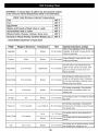
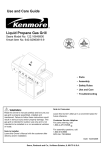
Use and Care Guide
®
Liquid Propane Gas Grill
Sears Model No. 122.16641900
Kmart Item No. 640-026629611-0
• Parts
• Assembly
• Safety Rules
• Use and Care
• Troubleshooting
//_
Note to Consumer
WARNING"
Read this Owner's manual carefully and be
sure your gas grill is properly assembled,
installed and maintained. Failure to follow
these instructions could result in serious injury
and/or property damage. This gas grill is
intended for outdoor use only and is not
intended to be installed in or on recreational
vehicles or boats.
Note to Installer
Leave this Owner's Manual with the customer
after delivery and/or installation.
Leave this Owner's Manual in a convenient
place for future reference.
Customer Service Helpline:
For parts ordering, call:
1-800-4-MY-HOME (_)
For assembly questions, call:
1-800-913-8999
MFG No: 720-0670A
Date: 10/20/2008
Sears, Roebuck and Co., Hoffman Estates, IL 60179 U.S.A.
Warranty
Safety Precautions.
Hardware List
_.I WARNING
.2
2~4
5
Parts Diagram
Parts List ................................................
Assembly Instructions.
Lighting Instructions
Cleaning and Maintenance ...................
Troubleshooting
Cooking Instruction
Cooking Chart
Combustion by products produced when using
this product contain chemicals known to the
State of California to cause cancer, birth defects,
or other reproductive harm.
.6
7
8~ 12
13~14
14~ 15
16
17
18
Failure to comply with these instructions could
resultWARNING
in a fire or explosion that could cause
I ,/'_,
serious bodily injury, death, or property damage.
/_WARNING
Your grill will get very hot. Never lean over the
cooking area while using your grill. Do not touch
cooking surfaces, grill housing, lid or any other
grill parts while the grill is in operation, or until
the gas grill has cooled down after use.
Failure to comply with these instructions may
result in serious bodily injury.
One-Year Full Warranty on Kenmore Grill
If this grill fails due to a defecting material or
workmanship within one year from the date of
purchase, call 1-800-4-MY-HOME to arrange for
free repair (or replacement if repair proves
impossible).
Ten-Year Limited Warranty
Burners
z_ WARNING
1.
on Stainless Steel
2.
For ten years from the date of purchase, any
stainless steel burner that rusts through will be
replaced free of charge. After the first year from
the date of purchase, you pay for labor if you
wish to have it installed.
Do not store or use gasoline or
other flammable liquids or
vapors in the vicinity of this or
any other appliance.
An LP cylinder not connected for
use shall not be stored in the
vicinity of this or any other
appliance.
DANGER
If you smell gas:
1.
Shut off gas to the appliance.
2.
Extinguish any open flame.
3.
Open lid.
4.
If odor continues, keep away
from the appliance and
immediately call your gas
supplier or your fire department.
All warranty coverage excludes ignitor batteries
and grill part paint loss, discoloration or rusting,
which are either expendable parts that can wear
out from normal use within the warranty period,
or are conditions that can be the result or normal
use, accident or improper maintenance.
All warranty coverage is void if this grill is ever
used for commercial or rental purposes.
All warranty coverage applies only if this grill is
used in the United States.
This warranty gives you specific legal rights, and
you may have other right which vary from state to
state.
Sears, Roebuck and Co.,
Hoffman Estates, IL 60179
U.S.A.
2
Grill Installation Codes
The installation must conform with local codes or,
in the absence of local codes, with either the
national fuel gas code, ANSI Z 223.1/NFPA $4,
Natural gas and propane installation code, CSA
B149.1, or propane storage and handling code,
B149.2, or the standard for Recreational vehicles,
ANSI A 119.2, and CSA Z240 RV series
recreational vehicle code, as applicable.
LP gas grill models are designed for use with a
standard 20 lb. Liquid Propane Gas tank, not
included with grill. Never connect your gas grill to
an LP gas tank that exceeds this capacity.
• Have your LP gas tank filled by a reputable
propane gas dealer and visually inspected and requalified at each filling.
• Do not store a spare LP gas tank under or
• near this appliance.
• Never fill the tank beyond 80 percent full. If this
information is not followed exactly a fire causing
death or serious injury may occur.
• Always keep LP gas tanks in an upright position.
• Do not store (or) or use gasoline or other
flammable vapors and liquids in the vicinity of this
gas grill.
• Do not subject the LP gas tank to excessive heat.
• Never store an LP gas tank indoors. If you store
your gas grill in the garage or other indoor
location, always disconnect the LP gas tank first
and store it safely outside.
A tankof approximately
12inchesindiameterby 181/2incheshighisthemaximumsizeLPgastankto
use.Youmustusean OPDgastankwhichoffers
an Overfill Prevention Device.
This safety feature prevents the tank from being
overfilled which can cause malfunction of the LP gas
tank, regulator and/or grill.
The LP gas tank must be constructed and marked in
accordance with specifications of the U.S. Dept. of
Transportation (DOT). In Canada, the LP gas tank
must meet the National Standard of Canada ,Can
CSA -B339, Cylinders, spheres and Tubes for
Transportation of Dangerous Goods and
Commission.
1. The LP gas tank must have a shutoff valve,
terminating in an LP gas supply tank valve outlet,
that is compatible with a Type 1 tank connection
device. The LP gas tank must also have a safety
relief device that has a direct connection with the
vapor space of the tank.
2. The tank supply system must be arranged for
vapor withdraw.
3. The LP gas tank used must have a collar to
protect the tank valve.
• Place dust cap on cylinder valve outlet whenever
the cylinder is not in use. Only install the type of
dust cap on the cylinder valve outlet that is
provided with the cylinder valve. Other types of
caps or plugs may result in leakage of propane.
• LP gas tanks must be stored outdoors in a wellventilated area and out of reach of children.
Disconnected LP gas tanks must not be stored in
a building, garage or any other enclosed area.
• When your gas grill is not in use the gas must be
turned off at the LP gas tank.
• The regulator and hose assembly must be
inspected before each use of the grill. If there is
excessive abrasion or wear or if the hose is cut, it
must be replaced prior to the grill being used
again.
• Keep the gas regulator hose away from hot grill
surfaces and dripping grease. Avoid unnecessary
twisting of hose. Visually inspect the hose prior to
each use for cuts, cracks, excessive wear or
other damage. If the hose appears damaged do
not use the gas grill. Call 1-800-4-MY-HOME for
assistance.
• Never light your gas grill with the lid closed or
before checking to ensure the burner tubes are
fully seated over the gas valve orifices.
• Never allow children to operate your grill.
Proper Placement and Clearance of Grill
Never use your gas grill in a garage, porch, shed,
breezeway or any other enclosed area. Your gas grill
is to be used outdoors only, at least 24 inches from
the back and side of any combustible surface. Your
gas grill should not be used under overhead
combustible construction. Do not obstruct the flow of
ventilation air around the gas grill housing.
• Do not install this outdoor gas grill in or on
recreational vehicles or boats
• Keep outdoor gas grill area clear and free from
combustible materials, gasoline and other flammable
vapors and liquids
• Do not obstruct the flow of combustion and
ventilation air. Check for this each time prior to using
grill.
• Never connect an unregulated LP gas tank to your
gas grill. The gas regulator assembly supplied with
your gas grill is adjusted to have an outlet pressure
of 11" water column (W.C.) for connection to an LP
gas tank.
• Only use the regulator and the hose assembly
supplied with your gas grill. Replacement regulators
and hose assemblies must be those specified in this
manual.
3
!
WARNING
A strong gas smell, or the hissing sound of gas
indicates a serious problem with your gas grill or
the LP gas tank. Failure to immediately follow the
steps listed below could result in a fire or
explosion that could cause serious bodily injury,
death, or property damage.
• Shut off gas supply to the gas grill.
• Turn the control knobs to OFF position.
• Put out any flame with a proper fire extinguisher.
• Open Grill Lid.
• Get away from the LP gas tank.
• Do not try to fix the problem yourself.
• If odor continues or you have a fire you can not
extinguish, call your fire department. Do not call
near the LP gas tank because your telephone is
a form of electrical device and could create a
spark resulting in fire and/or explosion.
NOTE: The normal flow of gas through the regulator
and hose assembly can create a humming noise. A
low volume of noise is perfectly normal and will not
interfere with operation of the grill. If humming noise
is loud and excessive you may need to purge air from
the gas line or reset the regulator excess gas flow
device. This purging procedure should be done every
time a new LP gas tank is connected to your grill. For
help with this procedure refer to page 14, Item 4 of "If
Grill Still Fails To Light", or call the Customer Service
Helpline 8 AM to 5 PM PST at: 1-800-913-8999
CAUTION: Spiders and small insects occasionally
spin webs or make nests in the grill burner tubes
during transit and warehousing. These webs can lead
to gas flow obstruction which could result in a fire in
and around burner tubes. This type of fire is known as
"FLASH-BACK" and can cause serious damage to
your grill and create an unsafe operating condition for
the user.
Although an obstructed burner tube is not the only
cause of "FLASH-BACK", it is the most common
cause.
To reduce the chance of "FLASH-BACK", you must
clean the burner tubes before assembling your grill,
and at least once a month in late summer or early fall
when spiders are most active. Also perform this
burner tube cleaning procedure if your grill has not
been used for an extended period of time.
See Cleaning Burner Tubes and Ports on page # 15
Visually check the burner flames prior to each use. The
flames should look like picture, if they do not, refer to the
cleaning burner tubes and ports, see page 15 of this
manual.
Repair Protection Agreements
Congratulations on making a smart purchase. Your new
Kenmore product is designed and manufactured for
years of dependable operation. But like all products, it
may require repair from time to time. That's when having
a Repair Protection Agreement can save you money and
aggravation.
Here's what the Repair Protection Agreement *
includes:
•,/ Expert service by our 10,000 professional repair
specialists
•"/ Unlimited service and no charge for parts and labor
on all covered repairs
,/ Product replacement up to $1500 if your covered
product can't be fixed
•"/ Fast help by phone - we call it Rapid Resolution phone support from a Sears representative. Think of
us as a "talking owner's manual"
Once you purchase the Repair Protection Agreement, a
simple phone call is all that it takes for you to schedule
service. You can call anytime day or night, or schedule a
service appointment online.
The Repair Protection Agreement is a risk-free purchase.
If you cancel for any reason during the product warranty
period, we will provide a full refund. Or, a prorated refund
anytime after the product warranty period expires.
Purchase your Repair Protection Agreement today!
Some limitations and exclusions apply. For prices
and additional information in the U.S.A. call 1 -800827-6655.
• Coverage in Canada varies on some items. For Full
details call Sears Canada at 1-800-361-6665
Sears Installation Service
For Sears professional installation of home appliances,
garage door openers, water heaters, and other major
home items, in the U.S.A. or Canada call 1-800-4-MYHOME
4
The following table illustrates a breakdown of the hardware pack. It highlights what components are used in
the various stages of assembly.
Item
1
2
Description
Phillips Head Screw
Phillips Head Screw
Specification
Quantity
1/4 x 1/2"
26 pcs
1/4 x 3/8"
4 pcs
5/32 x 3/8"
39 pcs
1/4"
30 pcs
5/32"
43 pcs
5/32 x 1/2"
2 pcs
Phillips Head Screw
3
Lock Washer
4
Flat Washer
5
Phillips Head Screw
6
Tank Bolt
7
1 pc
5
0.5----,_,
-26
6
%,,_-_58
KEY#
PARTS
KEY#
PARTS
1
2
32
33
670A-032
670A-033
Main Lid Screw
2
34
670A-034
Temperature
Hood Buffer
1
2
35
36
670A-035
670A-036
Logo
1
37
670A-037
670A-007
670A-008
Main Burner Bow I Assembly
Flange, Left
1
1
38
39
Flange, Right
Front Baffle
1
1
Main Gas Valve
1
670A-001
2
3
670A-002
670A-003
4
670A-004
5
6
670A-005
670A-006
7
8
DESCRIPTION
Main Lid
Main Lid Screw
QUANTITY
Cover
Gauge
DESCRIPTION
Door Magnet
Door Magnet Bracket
Front Door, Left
Door Handle
QUANTITY
2
1
1
2
1
1
670A-038
670A-039
Front Door, Right
Lighting Rod
Rubber Grommet
Back Panel
40
41
670A-040
670A-041
Back Panel, Top
Side Burner Front Panel
1
4
42
670A-042
Side Gas Valve
1
1
1
1
9
670A-009
10
11
670A-010
670A-011
12
13
670A-012
670A-013
Regulator, LP
Side Manifold
1
1
43
44
670A-043
670A-044
Side Burner Igniter Wire
Side Burner Pipel Assembly
1
1
14
670A-014
Side Burner Hose
1
45
670A-045
Side Burner Bow I Assembly
1
15
16
670A-015
670A-016
46
47
48
670A-046
670A-047
670A-048
1
1
670A-017
670A-018
1
1
1
Side Burner Cooking Grid
Side Burner Lid
17
18
Pulse Igniter Module
Main Manifold
Main Control Panel
Grease
Bezel
5
49
670A-049
Grease Tray
Main Burner Igniter Wire A
1
1
19
670A-019
Control Knob
5
50
670A-050
20
21
670A-020
670A-021
Side Shelf, Left
1
51
670A-051
22
670A-022
Side Shelf Front Panel,
Timer
1
1
52
53
670A-052
670A-053
23
24
670A-023
670A-024
Bottle Opener
Swivel Caster w ith Brake
1
1
54
55
670A-054
670A-055
25
26
670A-025
670A-026
Side Panel, Left
1
56
670A-056
27
670A-027
28
29
670A-028
670A-029
Side Panel, Right
Bottom Panel, LP
Swivel Caster
1
1
1
57
58
59
670A-057
670A-058
670A-059
Caster
2
60
670A-060
30
670A-030
Tank Bolt
1
31
670A-031
Cart Frame, Front
1
Left
For assembly questions, call:
1-800-913-8999
Slide Panel
1
Main Burner Igniter Wire B
Main Burner Igniter Wire C
1
1
Main Burner Igniter Wire D
Main Burner
1
4
4
Heat Diffuser
Cooking Grid with Hole
Warming Rack
Gas Tank Heat Shield Backet A
2
1
Gas Tank Heat Shield
Gas Tank Heat Shield Backet B
1
2
2
Important: Use only parts listed above. When ordering
parts, providing the following information:
1. Model #
For parts ordering, please call:
1-800-4-MY-H OM E_-,
2. Part Number (see PART# in chart)
3. Part Description
4. Quantity of parts needed
To make sure you obtain the correct replacement
parts for your Kenmore gas grill, please refer to
the part numbers on this page.
You can purchase the Kenmore rotisserie kit, item #
15803 at your local Sear's store.
Important: Keep this Owner's Manual for convenient
reference and for part replacement
7
Figure 2
CAUTION: While it is possible for one person to
assemble this grill, obtain assistance from another
person when handling some of the larger, heavier
pieces
1. Open lid of shipping carton and remove top
sheet of cardboard. Lay cardboard sheet on floor
and use as a work surface to protect floor and grill
parts from scratches.
2. Remove packing materials from shipping carton.
3. You may slice the carton front corners with a
utility knife to lay open the carton front panel. This
will allow you to raise the grill head lid and remove
the components packed inside the head.
Note: Be sure to slide grease tray out of back of
grill head and remove all packaging from tray.
Figure 3
4. Use the parts list to check that all parts have
been included.
5. Inspect the grill for damage as you assemble it.
Do not assemble or operate the grill if it appears
damaged. If there are damaged or missing parts
when you unpack the shipping box, or you have
questions during the assembly process, call:
For Assembly Questions, call 1-800-913-8999
8AM - 5 PM PST, Monday through Friday.
Figure 4
Assembling Grill Cart
1. Attach four casters to bottom panel using (16) ¼
x ½" Phillips head screws, (16) 1/4" lock washers.
Note: A is Swivel with Brake Caster, B is swivel
caster, C & D are straight casters. (Fig.l)
2. Attach left & right side panel to bottom panel
using (6) 5/32 x 3/8" Phillips head screws with (6)
5/32" lock washers. (Fig.2)
3. Attach back panel to side panel & bottom panel
using (7) 5/32 x 3/8" Phillips head screws with (7)
5/32" lock washers. (Fig.3)
4. Remove (4) 5/32 x 3/8" Phillips head screws and
5/32" lock washers from door handles firstly, then
attach door handles to doors. (Fig.4)
5. Attach doors to side panels using (4) 5/32 x 3/8"
flat head screws. (Fig. 5)
A
Figure 1
/
/
Figure 5
t
8
Installing Grill Head
1. Be sure grill cart doors are closed to stabilize cart.
Remove grill head from carton. Place onto cart from
above as shown in Figure 6.
CAUTION: Grill head is heavy. To avoid injury,
obtain the help of an assistant for this step. Also,
make sure doors remain closed when placing grill
head onto cart. DO NOT open doors until grill head
is securely mounted to cart.
2. Align screw holes of grill head with screw holes of
cart.
3. From back of cart, attach the grill head to the left and
right side (Fig. 7A) panels using (4) 1/4 x 3/8" Phillips
head screws and (4) 1/4" lock washers.
4. From the front of the cart, attach the front of the grill
head to the left and right side panels (Fig. 7B) using (2)
1/4 x 3/8" Phillips head screws and (2) 1/4" lock
washers
Figure 8
/
/
</
Installing Side Burner & Side Shelf
1. Assemble side shelf & side burner front panel using
(4) 5/32 x 3/8" Phillips head screws with (4) 5/32" lock
washers. (Fig. 8)
2. Remove (1) preinstalled 5/32 x 3/8 Phillips head
screw and (1) 5/32 lock washer from control panel. See
Figure 9 inset.
3. Screw (2) 1/4 x 1/2" Phillips head screws and (2) 1/4"
lock washers into side of grill head as shown. Do not
screw in fully; leave 1/4" extended for shelf assembly.
(Fig. 9)
4. Through side burner shelf screw holes, hang side
burner on two screws. (Fig. 10)
Figure 9
Figure 6
Figure 10
Figure 7
A
9
Figure 12
5. Using (3) 5/32 x 1/2" screws and (3) 1/2" lock
washers, securely attach side burner shelf to grill head.
Fully tighten two screws from previous step. Secure
side burner control panel to main control panel with
screw removed in step 2. (Fig. 11 )
A
6. Repeat steps 2 through 5 to install side shelf.
Installing Side Burner Valve
B
1. Remove the two screws attaching side burner to
underside of side burner shelf to make room to install
side burner valve. See Figure 12 A inset.
2. Remove two screws and washers from side burner
control valve face. Insert side burner valve control
stem through hole in side burner control panel. See
Figure 12 B.
3. Place side burner control knob bezel over side
burner valve control stem. Secure bezel to control and
valve with 2 screws removed in step 2. Push control
knob onto valve control stem. See Figure 13.
4. Insert valve orifice tip into burner tube as shown in
Fig. 12. Reattach burner to underside of side burner
shelf with screws removed in step 1.
5. Plug ignition wire into igniter wire electrode on
underside of burner(Fig. 14).
Figure 13
I sure
Whenthat
youallhave
finished
assembling
screws
and nuts
are tightgrill,
and make
secure.
Installing Battery
1.Unscrew the ignition battery cap. (Found at far left of
control panel).
Figure 14
2.Install battery into ignition box with positive terminal
facing outward.
3.Replace the ignition battery cap after the battery has
been installed. (Fig. 15)
3pcs: ¼ X ½"
1pc: ¼ X ½"
Figure 11
Figure 15
/
1pc: 5/32 X ½"
/
/
10
Installing Gas Tank Heat Shield
Figure 17
1. Assemble 2pcs longer gas tank heat shield bracket
A to gas tank heat shields using (2) 5/32 x 3/8" Phillips
head screws with (4) 5/32" lock washers from up to
down (Fig. 16 A)
2. Assemble 2pcs shorter gas tank heat shield bracket
B to gas tank heat shields as above, but assembly
screws need to from down to up, finish preassembly
whole gas tank heat shield (Fig. 16 B).
3. Attach gas tank heat shield bracket A other end to
back panel using (2) 5/32 x 3/8" Phillips head screws
with (4) 5/32" lock washers as shown (Fig. 17)
4. Attach gas tank heat shield bracket B other end to
cart frame using (2) 5/32 x 3/8" Phillips head screws
with (4) 5/32" lock washers as shown (Fig. 18)
Figure 18
Installing grease cup
From the back, pull out grease tray, remove any
packaging materials from it, then replace grease
cup into grease tray as shown in (Fig. 19). Push
grease tray back into grill.
Figure 16
B
/
\
/
i
/
/
Figure 19
A
11
Figure 20
Installing Cooking Components
Important: Before cooking on your grill the first time,
wash cooking grids and cooking rack with warm,
soapy water. Rinse and dry thoroughly. Season with
cooking oil regularly. After cooking is completed, turn
grill to HIGH setting for 3 to 5 minutes to burn off
excess grease or food residue.
1. Install heat diffusers above burners. Holes in
corners of diffusers attach onto pegs in front and
back ledge of firebox. Ensure that firebox heat shield
is inserted securely into slots. If grill was shipped
with shield taped in place, remove tape before using
grill.
2. Evenly space cooking grids on the ledge above
heat diffusers. (Fig.20)
Figure 21
3. Insert legs of warming rack into the holes in the
top of grill bowl side panels. (Fig.20)
Connecting LP Gas Tank to LP Grill
1.Remove the screw on tank bolt & take off the
washer. Insert the tank bolt from rear of the grill and
reinstall the washer & screw set. From Rear of the
cart, place foot ring of 20 Ib tank into the hole in
bottom panel. Make sure the tank valve is in OFF
position. Use the tank bolt to secure the tank in a
fixed position (Fig.21).
2. Check the tank valve to ensure it has proper
external mating threads to fit the hose and regulator
assembly provided.
3. Make sure all burner valves are in OFF position.
4. Inspect the valve connection port and regulator
assembly. Look for damage or debris. Remove any
debris. Inspect hose for damage. Never use
damaged or plugged equipment.
5. When connecting regulator and hose assembly to
tank valve hand tighten quick coupling nut clockwise
to a full stop (Fig.22) Do not use a wrench to tighten
because it could damage the quick coupling nut and
result in a hazardous condition.
6. Open tank valve fully (counterclockwise). Use a
soapy water solution to check all connections for
leaks before attempting to light your grill. If a leak is
found, turn tank valve off and do not use your grill
until the leak is repaired.
Figure 22
Regulator Connection
Congratulations
Your Kenmore gas grill is now ready for use.
Before the first use and at the beginning of each
season (and whenever the LP gas tank has been
changed):
1. Read all safety, lighting and operating
instructions.
2. Check gas valve orifices, burner tubes and
burner ports for any obstructions.
3. Perform gas leak check according to
instructions found on next page of the manual.
CAUTION: When the appliance is not in use, gas
must be turned off at the supply tank.
12
Checking for LP gas leaks
,
Never test for leaks with a flame. Prior to first use, at
the beginning of each season, or every time your LP
gas tank is changed, you must check for gas leaks.
4.
5.
Be sure all gas connections are securely
tightened.
Open the grill main lid and side burner lid.
Push and turn any main burner knob to,j_HI
position, holding knob and Electronic ignition""
button for 3 to 5 seconds to light burner.
1. Make a 50/50 (soap/water) mild soap solution.
2. Turn the control knobs to full OFF position; then
turn gas ON at supply tank.
3. Apply the soap solution with a clean brush to all
gas connections. See below. If growing bubbles
appear in the solution the connections are not
properly sealed. Check each fitting and tighten or
repair as necessary.
Gas Connection Leak Check
6.
7.
4. If you have a gas connection leak you cannot
repair, turn gas OFF at supply tank, disconnect
fuel line from your grill and call 1-800-4-MY-HOME
or your gas supplier for repair assistance.
5. Also apply soapy solution to the tank seams. See
below. If growing bubbles appear, shut tank OFF
and do not use or move it! Contact an LP gas
supplier or your fire department for assistance.
8.
To light additional burners, turn burner
knob(s) to_ HI. Push and hold electronic
ignition button to light burner. Adjust knob(s)
to desired setting.
If the burner does not light after 5 seconds,
turn knob to OFF. Turn gas OFF at LP tank
and wait 5 minutes for gas to clear. Then
turn gas ON at tank and repeat step 5
If burner still does not light, see Match
Lighting section and If Grill Still Fails to Light
section on following page.
USING THE SIDE BURNER:
Inspect the gas supply hose prior to turning the gas
"ON". If there is evidence of cuts, wear or abrasion,
it must be replaced prior to use. Do not use the
side burner if the odor of gas is present.
WARNING: Always keep your face and body as
far away from the burner as possible when
lighting.
Gas Tank Leak Check
LIGHTING INSTRUCTIONS
FOR SIDE BURNER
1. Open side burner lid fully.
2. Push and turn side burner knob to J_HI position.
Push and hold Electronic Ignition button for 3-5
seconds to light burner. If the side burner does
not light after 5 seconds, turn knob to OFF. Turn
gas OFF at LP tank and wait 5 minutes for gas
to clear. Then turn gas ON at tank and repeat
step 2.
3. If burner still does not light, see Match Lighting
section and If Grill Still Fails to Light Section on
following page.
Grill Lighting Instructions for Main Burners
1. Do not smoke while lighting grill or checking gas
supply connections.
2. Be sure that LP gas tank is sufficiently full.
/_
WARNING
Failure to open grill lid during the lighting
procedure could result in a fire or explosion
that could cause serious bodily injury, death,
or property damage.
13
\
WARNING
Never lean over the grill cooking area while
lighting your gas grill. Keep your face and body
a safe distance (at least 18 inches) from the
cooking grid surface when lighting your grill by
match.
Manually Lighting Your Grill by Match
1. Take the manual lighting stick
2. Insert a match into the lighting stick.
3. Follow steps 1 through 5 of the Basic Lighting
Procedure.
4. Light the match and extend the lighting stick to
cooking grid surface.
5. Turn the desired control knob to the HI/position
setting to release gas. The burner should light
immediately.
If Grill Still Fails To Light
1. Check gas supply and connections for leaks. Check
that all wire connections are secure.
2. Repeat basic lighting procedure. If your grill still fails
to operate, turn the gas off at source, turn the control
knobs to OFF, then check the following:
• Misalignment of burner tubes over orifices
Correction: Reposition burner tubes over orifices.
•Obstruction in gas line
Correction: Remove fuel line from grill. Do not smoke!
Open gas supply for 1 second to clear any obstruction
from fuel line. Close off gas supply at source and
reconnect fuel line to grill.
• Plugged orifice
Correction: Remove burners from grill, carefully lift
each burner up and away from gas valve orifice.
Remove the orifice from gas valve and gently clear any
obstruction with a fine wire. Then reinstall all orifices,
burners, and cooking components.
3. If an obstruction is suspected in gas valves, please
call for repair service at 1-800-4-MY-HOME.
4. If the grill still does not light you may need to purge air
from the gas line or reset the regulator excess gas flow
device. Note: This procedure should be done every time
a new LP gas tank is connected to your grill.
To purge air from your gas line and/or reset the
regulator excess gas flow device:
• Turn the control knob to OFF position.
• Turn off the gas at the tank valve.
• Disconnect regulator from LP gas tank.
• Let unit stand for 5 minutes.
!
WARNING
Should a "FLASH-BACK"
fire occur in/or
around the burner tubes, follow the instructions
below. Failure to comply with these instructions
could result in a fire or explosion that could
cause serious bodily injury, death, or property
damage.
• Shut off gas supply to the gas grill.
• Turn the control knobs to OFF position.
• Put out any flame with a proper fire extinguisher.
• Open grill lid.
• Once the grill has cooled down, clean the burner
tubes and burners according to the cleaning
instructions found on page 15.
• Reconnect regulator to the LP gas tank.
• Turn the tank valve on slowly until 1¼to ½ open.
• Open the grill lid.
• Set control knobs to OFF. Push and turn any control
knob to HIGH.
• Turn control knobs to HIGH until all the burners are lit
• You may start to use the grill
5. If all checks or corrections have been made and you
still have questions about operating your gas grill, call
the Customer Service Helpline 8 AM - 5 PM PST,
Monday through Friday at 1-800-913-8999
14
Cleaning Exterior Stainless Steel Surfaces
To ensure a proper working unit the following proper
care and maintenance is suggested.
Cleaning Cooking Grids
We suggest you wash your cooking grids in a mild soap
and warm water solution. You can use a wash cloth or
soft brush to clean your cooking grids.
Cleaning Heat diffusers
Periodically you should wash the heat diffusers in a
soap and warm water solution. Use a soft brush to
remove stubborn burnt-on cooking residue. The heat
diffusers should be dry before you reinstall them.
•Weathering and extreme heat can cause exterior
stainless steel surfaces to turn tan in color. Machine
oils used in manufacturing process of stainless steel
can also cause this tanning color. Use a stainless
steel cleaner to polish stainless steel surfaces of
your grill. Never use abrasive cleaners or scrubbers
because they will scratch and damage your grill.
Cleaning Burner Tubes and Burner Ports
To reduce the chance of "FLASH-BACK" the procedure
below should be followed at least once a month in late
Cleaning Grease Tray
The grease tray should be emptied and wiped
down periodically and washed in a mild
detergent and warm water solution. A small
amount of sand or cat litter may be placed in
bottom of grease tray to absorb the grease.
Check the grease tray frequently, don't allow
excess grease to accumulate and overflow out of the
grease tray.
summer or early fall when spiders are most active or
when your grill has not been used for a period of time.
Annual Cleaning of Grill Interior
Burning-off the grill after every use will keep it ready for
your next use. However, once a year you should give
the entire grill a thorough cleaning to keep it in top
operating condition. Follow these steps.
1. Turn all burner valves to full OFF position.
2. Turn LP gas tank valve to full OFF position.
3. Detach LP gas hose and regulator assembly from
your gas grill. Inspect for any damage and replace as
necessary with manufacturer replacement part number
found on parts list.
4. Remove and clean heat diffusers, cooking grids and
grill burners.
5. Cover each gas valve orifice with aluminum foil.
6. Brush inside and bottom of grill with a nylon brush,
and wash with a mild soap and warm water solution.
Rinse thoroughly and let dry.
7. Remove the aluminum foil, then reinstall heat
diffusers, and cooking grids.
8. Reconnect gas source and observe burner flame for
correct operation.
burner and lift the burners up and away from the gas
valve orifice.
1. Turn all burner valves and gas tank valve to off
position.
2. Detach the LP gas regulator assembly from your gas
grill.
3. Remove cooking grids, heat diffusers, and grease
tray from the grill.
4. Remove the screws from the underside of each
Cleaning Exterior Surface
•We suggest you wash your grill using a mild soap and
warm water solution. You can use a wash cloth or
sponge for this process. Do not use abrasives or a
brush that might remove finish during the cleaning
process.
15
5. Using a bent stiff wire in the shape of a hook, air
hose or a bottle brush, run it through the burner tube
and inside several times to remove any debris.
6. Replace burners, see illustration below.
Step 1. Locate the burner onto the orifice.
Step 2. Secure the main burner on the back wall of fire
box with 2 screws.
_.I
WARNING
The location of the burner tube with respect to the
orifice is vital for safe operation. Check to ensure the
orifice is inside the burner tube before using the gas
grill. If the burner tube does not fit over the valve
orifice, lighting the burner may cause explosion
and/or fire.
Regardless of which burner cleaning procedure you
use, we recommend you also complete the following
steps to help prolong burner life.
1. Use a fiber pad or nylon brush to clean the entire
outer surface of each burner until free of food residue
and dirt.
3. Inspect each burner for damage (cracks or holes)
and if such damage is found, order and install a new
burner. After installation check to ensure that gas
valve orifices are correctly placed inside the ends of
the burner tubes.
/_
Spiders and insects can nest inside the burners of
the grill and disrupt gas flow. This very dangerous
condition could cause a fire behind the valve panel,
thereby damaging the grill and making it unsafe
for operation. Inspect the grill at least twice a year.
2. Clean any clogged ports with a stiff wire, such as
an open paper clip.
BEFORE CALLING
WARNING
FOR SERVICE
If the grill does not function properly, use the following check list before calling for service.
You should inspect the burners at least once a year or immediately after any of the following
conditions occur:
I:,1=(o]:] ml=!L%.'-]
;ivj: r:_liI/l[O] lelo]
Grill won't light when the control knob is
rotated.
Check to see if LP tank is empty.
Clean wires and/or electrode by rubbing
with alcohol and clean swab.
Wipe with dry cloth.
Make sure the wire is connected
to
electrode assembly.
Do other burners on the unit operate?
Check to see if other burners operate. If
so, check the gas orifice on the
malfunctioning
burner for an obstruction.
Burner flame is yellow or orange, in
combination with the odor of gas.
Refer to Clean Burner Tubes and Burner
Low heat with knob in "HI" position.
Is the fuel hose bent or kinked?
Ports on page 15. If problem still exists,
31ease call 1-800-913-8999.
Is the grill in a dusty area?
Is there adequate gas supply available?
If it is only one burner that appears low,
does the orifice or burner need cleaning?
Is the gas supply or gas pressure low?
16
Indirect Cooking
To cook indirectly, the food should be placed on
the left or right side of your grill with the burner lit
on the opposite side. Indirect cooking must be
done with the Lid down.
.1_
WARNING
Do not leave the grill unattended.
Your grill will get very hot. Never lean over
the cooking area while using your grill. Do not
touch cooking surfaces, grill housing. Grill Lid
or any other grill parts while the grill is in
operation, or until the grill has cooled down
after use. Failure to comply with these
instructions may result in serious bodily injury.
Flare-ups
The fats and juices dripping from grilled food can
cause flare-ups. Since flare-ups impart a
favorably,distinctive taste and color to food cooked
cover an open flame, they should be accepted up
to a point. Nevertheless, uncontrolled flaring can
result in a ruined meal.
Burn-off
Before cooking on your gas grill for the first time,
you will want to "burn off" the grill to eliminate any
odor or foreign matter. Just ignite the
burners,lower the Lid, and operate grill on the
HIGH setting for 3 to 5 minutes.
Cooking
CAUTION
To prevent damage to adjacent burner (s), the
fire box heat shield must be securely inserted
in place when operating the Searing burner.
Temperatures
High setting: Only use this setting for fast
warm-up,searing steaks or chops and for burning
food residue off the grill after cooking is complete.
Never use the HIGH setting for extended cooking.
Medium to Low Settings: Most recipes specify
medium to low settings, including all smoking,
rotisserie cooking and for cooking lean cuts such
as fish.
NOTE: Temperature settings will vary with the
temperature and the amount of wind outside your
home.
Direct Cooking
The direct cooking method can be used with the
supplied cooking grids and food placed directly
over the lit grill Burners. Direct cooking requires
the grill lid to be up.The method is ideal for
searing and whenever you want meat, poultry or
fish to have and open-flame barbecued taste.
Deep frying and smoking are also best cooked in
this manner because they require direct heat.
//_ WARNING
Do not line the bottom of the grill housing with
aluminum foil, sand or any substance that will
restrict the flow of grease into the grease tray.
Failure to comply with these instructions could
result in a fire or explosion which could cause
serious bodily injury, death, or property
damage.
17
WARNING: To ensure that it is safe to eat, food must be cooked
to the minimum intema| temperatures listed in the table below.
USDA*
Safe Minimum
internal
Temperatures
Fish
145 ° F
Pork
160 ° F
Egg Dishes
160 ° F
Steaks and Roasts of Beef_ Veal or Lamb
t45 ° F
Ground
160 ° F
Beef, Veal or Lamb
Whole Poultry (Turkey, Chicken,
Ground
165 ° F
Duck, etc.)
or Pieces Poultry (Chicken
Breast,
165 ° F
etc.)
* United States Depa_ment of Agricu|ture
FOOD
Weight or thickness
Temperature
Vegetables
NA
Medium
Potatoes
Whole
Medium
Meat/Steaks
Ground Meats
1/2 to 3/4 inches
1/2 to 3/4 inches
High-Medium
Medium
Time
8 to 20 minutes
Special instructions and tips
Slice or chop vegetables and dot with butter or
margarine. Wrap tightly in heavy duty foil. Grill
turning occassionally.
40 to 60 minutes Wrap individually in heavy duty foil. Cook
rotating occassionally.
4 to 15 minutes
8 to 15 minutes
Pre heat grill for 15-20 minutes then sear
steaks on each side for two minutes. Next
grill 3 to 5 minutes on each side or until
desired doneness.
Grill turning once when juices rise to the
surface or until desired amount d doneness.
Do not leave hamburgers unattended since a
flare-up could occur quickly.
Ribs
1/2 or full rack
Medium
Hot dogs
NA
Medium
Poultry-Cut
1/4 to 1/2 pounds
Low or Medium
Poultry Whole
Fish
Grill turning occassionally. During last few
20 to 40 minutes minutes brush with barbecue sauce, turn
several times.
5 to 10 minutes
Grill turning occassionally. During last few
20 to 40 minutes minutes brush with barbecue sauce if desired,
turn several times.
Low or
1 to 1-1/2 hours
Use poultry stand and brush frequently as
desired
Medium
40 to 60 minutes
Use poultry stand and brush frequently as
desired
Medium
8 to 15 minutes
2 to 3 pounds
3/4 to 1 inch
Grill turning four times. 2-4 minutes on each ol
four sides.
18
Grill turning once to desired doneness. Brush
with melted butter, margarine or oil.
Your Home
For expe_ troubleshooting
and home solutions advice:
w-wwomanagemyhome.com
For repair - in your home - of all major brand appliances,
lawn and garden equipment, or heating and cooling systems,
no matter who made it, no matter who sold it!
For the replacement pa_s, accessories and
owner's manuals that you need to do-it-yourself.
For Sears professional installation of home appliances
and items like garage door openers and water heaters.
1-800-4-MY-H OM E®
Call anytime,
day or night (U.S.A. and Canada)
_:
our Home
::
For repair of carry-in items like vacuums, lawn equipment,
and electronics, call anytime for the location of your nearest
_
.
.
Stars Pa_s&RepairSer_icetenter
1 800 488 1222 (U.S.A.)
1 800 469 4663
www.sears.com
:
To purch:se
ii_il
: protection
!_!i
(Canada)
www.sears,ca
agreement
1 800 827 6655 (U.S.A,)
Para pedir servicio de reparaci6n
a domicilio,
y para ordenar piezas'
......
°n tnprOduct s:rviced
1 o00 361 6665
by Sears:
(Canada)
Au Canada pour service en frangais:
1-800-LE . FOYER MC
1"888"SU'HOGAR®
800 533 6937 )
( 1.......
www,sears.ca
(1-888-784-6427)
_i i;
.....
® Registered Trademark ! TM Trademark / S_ Service Mark of Sears Brands, LLC
® Marca R_istrada / TMMarca de Fabrlca i s_ Marca de Serv_c_ode Sears Brands, LLC
MC Maroue
de commerce
f Me Maraue
d_eos_e
de Sears
Brands.
i_
:!;t
LLC
© Sears
Brands.
LLC