1
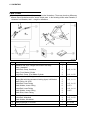
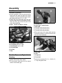
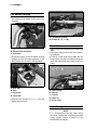
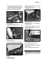
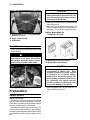
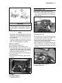
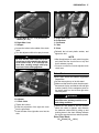
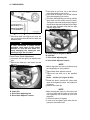
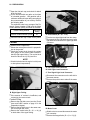
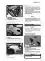
®
Ninja 650R
ER-6f
ER-6f ABS
Motorcycle
Assembly & Preparation
Manual
Foreword
In order to ship Kawasaki vehicles as efficiently as possible, they are partially disassembled before crating. Since some of the most
commonly removed parts have a direct bearing on a vehicle’s reliability and safety, conscientious pre-sale assembly and preparation becomes extremely important. Good setup procedures can prevent needless warranty claims
and give customers a greater sense of confidence in Kawasaki and their Kawasaki Dealers.
This Assembly and Preparation Manual explains step by step procedures of the following
items for the Kawasaki Ninja 650R, ER-6f and
ER-6f ABS.
WARNING
This warning symbol identifies special
instructions or procedures which, if not
correctly followed, could result in personal injury, or loss of life.
CAUTION
This caution symbol identifies special
instructions or procedures which, if not
correctly followed, could result in damage to, or destruction of equipment.
NOTE
1. Uncrating
2. Assembly
3. Preparation
This note symbol indicates points of particular
The selling dealer assumes sole responsibility for any unauthorized modifications prior to
sale. Refer to your Service Binder for any Service Bulletins specifying Factory Directed Modifications (Special Claims) which must be performed before the vehicle is ready for sale.
Whenever you see the following symbols
heed their instructions! Always follow safe
operating and maintenance practices.
Kawasaki Heavy Industries, Ltd. accepts no
liability for any inaccuracies or omissions in this
publication, although every possible measure
has been taken to make it as complete and accurate as possible. All procedures and specifications subject to change without notice.
© 2008 Kawasaki Heavy Industries, Ltd.
interest for more efficient and convenient operation.
Dec., 2008
Table of Contents
Uncrating ......................................................................................
Opening Crate .............................................................................
Parts Check .................................................................................
Assembly ......................................................................................
Handlebar....................................................................................
Throttle Grip and Right Switch Housing ......................................
Front Brake Master Cylinder .......................................................
Cables, Harness and Hoses Routing ..........................................
Left Switch Housing.....................................................................
Clutch Cable................................................................................
Lower Fairing...............................................................................
Windshield...................................................................................
Brake Disc Cleaning ....................................................................
Preparation ...................................................................................
Battery Service ............................................................................
Front Brake Fluid.........................................................................
Rear Brake Fluid .........................................................................
Clutch Lever and Cable ...............................................................
Drive Chain..................................................................................
Rear Shock Absorber ..................................................................
Tire Air Pressures........................................................................
Fuel .............................................................................................
Coolant ........................................................................................
Engine Oil (4-stroke) ...................................................................
Idle Speed Adjustment ................................................................
Throttle Grip and Cable ...............................................................
Rear Brake Light Switch ..............................................................
Headlight Aim ..............................................................................
Digital Meter ................................................................................
Fastener Check ...........................................................................
Standard Torque Table ................................................................
Test Ride the Motorcycle .............................................................
A&P Check List ...........................................................................
3
3
4
5
5
5
6
7
8
8
8
9
10
10
10
13
14
16
17
19
19
19
20
21
22
23
24
24
25
26
28
28
28
UNCRATING 3
Uncrating
Opening Crate
WARNING
Always wear protective gloves, boots
and eye protection when uncrating to
prevent injury.
WARNING
Be careful not to injure your body by
the sharp edges of the steel crate panel
plates and other sharp fasteners.
remove the lower bolts (D = 8, L = 16)
• First,
at the steering stem and discard them.
the upper bolts (D = 8, L = 22) to
• Remove
take off the steering stem support bracket and
•
•
discard them.
Remove the lower bolts (D = 6, L = 12) and
washer to take off the front master cylinder.
Remove the upper bolt (D = 8, L = 16) to take
off the front master cylinder support bracket
and discard it.
A. Lower Bolts (D = 8, L = 16)
B. Upper Bolts (D = 8, L = 22)
C. Steering Stem Support Bracket
D. Lower Bolt (D = 6, L = 12) and Washer
E. Lower Bolt (D = 6, L = 12)
F. Front Master Cylinder
G. Upper Bolt (D = 8, L = 16)
H. Front Master Cylinder Support Bracket
out all the bolts and screws and remove
• Take
the top and sides of the crate.
NOTE
Roll
a space about 6 m (20 ft) square to give
• Clear
yourself plenty of space to work.
the crate upright on its base.
• Place
Remove
the cardboard cover.
• Remove the
handlebar and the parts box.
•
CAUTION
When removing the crate bracket from
the motorcycle, be careful not to drop
any parts or the bracket onto the fuel
tank and other components, and not to
scratch the fuel tank or other components with the crate bracket.
the vehicle off the crate base after installing the handlebar and front master cylinder.
4 UNCRATING
Parts Check
the parts box, and check the parts against the illustrations. There may be minor differences
• Open
between these illustrations and the actual vehicle parts. In the following charts under Remarks, D
= diameter in millimeters, and L = length in millimeters.
No.
1
2
3
4
5
Part Name
Handlebar with Grips, Weights and Clutch Lever Assy
Clamp, Handlebar
Socket Bolt, Clamp, Handlebar
Clamp, Front Master Cylinder
Socket Bolt, Clamp, Front Master Cylinder
Left Bracket, Lower Fairing
Flanged Bolt with Non-permanent Locking Agent, Left Bracket
Lower Fairing, LH & RH
Socket Bolt, Lower Fairing
Plastic Washer, Lower Fairing
Socket Bolt, Lower Fairing
Plastic Washer, Lower Fairing
Plastic Rivet, Lower Fairing
Windshield
Socket Bolt, Windshield
Plastic Washer, Windshield
Battery Electrolyte, FTX12-BS
Owner’s Manual
Qty
1
1
4
1
2
1
2
2
6
6
2
2
3
1
4
4
1
1
Remarks
D = 8, L = 30
D = 6, L = 22
D = 6, L = 14
D = 5, L = 16
D = 5.3
D = 6, L = 14
D = 6.5
D = 5, L = 20
D = 5.3
12 V 10 Ah
ASSEMBLY 5
Assembly
Handlebar
Handlebar Installation
the handlebar so that its punched mark is
• Set
aligned with the upper rear edge of the lower
handlebar clamp and install the upper handlebar clamp and bolts (D = 8, L = 30).
Tighten the front clamp bolts first, and then
the rear clamp bolts to the specified torque.
There will be a gap at the rear part of the
clamp after tightening.
Torque: 25 N·m (2.5 kgf·m, 18 ft·lb)
•
A. Throttle Grip
B. Cable Tips : Apply Grease.
C. Rear Half
D. Throttle Cable (Decelerator)
E. Throttle Cable (Accelerator)
the two halves of the right switch housing
• Fit
so that the projection on the front half fits into
the hole in the handlebar.
A. Handlebar Clamp (Upper)
B. Front Bolts (D = 8, L = 30)
C. Rear Bolts (D = 8, L = 30)
D. Punched Mark
E. No Gap
F. Gap
Throttle Grip and Right Switch
Housing
a light coat of grease on the exposed
• Apply
portion of the throttle inner cables.
both throttle cable tips into the nearest
• Fit
socket in the throttle grip.
A.
B.
C.
D.
Rear Half
Hole
Projection
Front Half
the two screws (D = 5, L = 25) (D = 5,
• Insert
L = 40) and tighten them.
6 ASSEMBLY
A. Right Switch Housing
B. Screw (D = 5, L = 25)
C. Screw (D = 5, L = 40)
Front Brake Master Cylinder
the right switch housing lead con• Connect
nectors to the front brake light switch terminals on the front brake master cylinder.
A. Front Master Cylinder
B. Brake Light Switch Terminals
C. Connectors and Dust Covers
the front master cylinder with its clamp
• Install
and the two bolts (D = 6, L = 22).
the master cylinder so that the mat• Position
ing surface of the front and rear master cylinder clamps align with the punched mark on
the handlebar.
A.
B.
C.
D.
Front Master Cylinder
Clamp
Punched Mark
Bolts (D = 6, L = 22)
the upper clamp bolt first and then the
• Tighten
lower clamp bolt to the specified torque.
Torque: 11 N·m (1.1 kgf·m, 97 in·lb)
ASSEMBLY 7
Cables, Harness and Hoses Routing
• Check that the cables, wiring leads and hoses are routed correctly.
Right Side View
Left Side View
A. Right Switch Housing Harness
F. Left Switch Housing Harness
B. Throttle Cable (Accelerator)
G. Clutch Cable
C. Throttle Cable (Decelerator)
H. Run the clutch cable and left switch
D. Front Brake Hose
housing harness through the guide.
E. From the inside sequentially, run the right switch I. Run the left switch housing harness
housing harness, front brake hose, throttle cathrough the guide.
ble (decelerator) and throttle cable (accelerator)
through the guides.
8 ASSEMBLY
Left Switch Housing
the left switch housing connector to
• Connect
the starter lock-out switch on the clutch lever
assembly.
A. Left Switch Housing
B. Screws (D = 5, L = 25)
Clutch Cable
A. Clutch Lever Assy
B. Starter Lock-out Switch
C. Connector
the two halves of the left switch housing
• Fit
together so that the small projection on the
front half fits into the hole in the handlebar.
A.
B.
C.
D.
Rear Half
Hole
Projection
Front Half
the two screws (D = 5, L = 25) and
• Insert
tighten them securely.
a light coat of grease on the clutch inner
• Apply
cable.
up the slots on the clutch lever, locknut,
• Line
and adjuster.
the tip of the clutch inner cable into the
• Fit
lever socket, slide the inner cable through the
slots, and release the outer cable into the adjuster.
A. Clutch Cable
B. Adjuster
C. Locknut
D. Cable Tip
E. Clutch Lever
Lower Fairing
NOTE
It
is recommended that the lower fairing
should be installed after completing the steps
in the “Coolant” section on page 20 in the
PREPARATION chapter.
ASSEMBLY 9
the left bracket on the lower left side
• Install
of the engine with the flanged bolts (D = 6, L
= 14) (2) with non-permanent locking agent,
and tighten the bolts to the specified torque.
Torque: 12 N·m (1.2 kgf·m, 106 in·lb)
A. Left Bracket
B. Flanged Bolts (D = 6, L = 14)
the left upper fairing outward to clear the
• Pull
stopper.
the socket bolts (D = 5, L = 16) (3) and
• Install
plastic washers (D = 5.3) (3).
the socket bolt (D = 6, L = 14) and
• Install
plastic washer (D = 6.5).
A. Socket Bolts (D = 5, L = 16) and Plastic
Washers (D = 5.3)
B. Socket Bolt (D = 6, L = 14) and Plastic
Washer (D = 6.5)
the right lower fairing in the same man• Install
ner as the left lower fairing.
the left and right lower fairings with
• Fasten
three plastic rivets.
A. Clear the stopper.
B. Left Upper Fairing
the tabs into the slots to fit the left lower
• Insert
fairing on the inside of the left upper fairing.
A. Plastic Rivets
B. Left and Right Lower Fairings
the socket bolts (D = 5, L = 16).
• Tighten
the socket bolts (D = 6, L = 14) to the
• Tighten
specified torque.
Torque:
8.8 N·m (0.90 kgf·m, 78 in·lb)
Windshield
the windshield on the upper center fair• Install
ing with the socket bolts (D = 5, L = 20) (4) and
plastic washers (D = 5.3) (4), and tighten the
bolts.
A.
B.
C.
D.
Tabs
Slots
Left Upper Fairing
Left Lower Fairing
10 PREPARATION
CAUTION
Incorrect Battery Activation will reduce
battery performance and service life. Be
sure to strictly follow the Battery Service
instructions in this Manual.
sure to use the electrolyte packed in the
• Make
crate with the unit.
sure that the model name of the elec• Make
trolyte container matches the model name of
the battery. These names must be the same.
Battery Model Name for
A. Socket Bolts (D = 5, L = 20) and Plastic
Washers (D = 5.3)
B. Upper Center Fairing
C. Windshield
EX650C/D: FTX12-BS
Brake Disc Cleaning
the front and rear brake discs using
• Clean
oilless solvent.
WARNING
If not removed, the anticorrosive treatment applied to the brake disc surface
will interfere with brake action, and an
unsafe riding condition could result.
A. Model Name of the Electrolyte
B. Model Name of the Battery
CAUTION
Sealed battery electrolyte has a higher
concentration of sulfuric acid. Each
container contains the proper amount
of electrolyte for its specific battery.
Insufficient or incorrect electrolye will
reduce battery performance and service
life. Electrolyte over capacity can lead
to battery cranking or leaking and result
in corrosion damage to the vehicle.
Preparation
Battery Service
Battery Removal
The battery used in this motorcycle is a sealed
type and never needs to be refilled. Follow the
procedure for activating a new battery to ensure
the best possible battery performance.
Activating the battery requires two steps, filling the battery with electrolyte, and charging.
Read the electrolyte safety label and the following procedures carefully before battery activation.
the ignition key into the seat lock, lo• Insert
cated under the seat cover.
PREPARATION 11
Battery Activation
Filling the Battery with Electrolyte
CAUTION
Do not remove the aluminum sealing
sheet [A] from the filler ports [B] until
just prior to use. Be sure to use the dedicated electrolyte container for correct
electrolyte volume.
A.
B.
C.
D.
the battery on a level surface.
• Place
Check
see that the sealing sheet [A] has no
• peeling,totears,
or holes in it.
Remove
the
sealing
sheet [A].
•
Seat
Seat Lock
Ignition Key
Insert
NOTE
The battery is vacuum sealed.
the key clockwise while pulling the rear
• Turn
end of the seat.
the seat backward.
• Remove
Run
the
suitable
band into the positive termi• nal (+).
the battery out of the battery case with
• Pull
both hands.
If the sealing
sheet has leaked air into the battery, it may
require a longer initial charge.
the electrolyte container from the
• Remove
vinyl bag.
the strip of caps [A] from the container
• Detach
and set aside, these will be used later to seal
the battery.
NOTE
A. Battery
B. Suitable Band
•
Do not pierce or otherwise open the sealed
cells [B] of the electrolyte container. Do not
attempt to separate individual cells.
Clean the terminals.
Battery Specifications
Make
Battery Type
Battery Capacity
Electrolyte Capacity
Battery/Electrolyte Set P/No.
Furukawa
FTX12-BS
12 V 10 Ah
0.60 L
26012-0109
12 PREPARATION
the electrolyte container upside down
• Place
with the six sealed cells into the filler ports
of the battery. Hold the container level, push
down to break the seals of all six cells. You
will see air bubbles rising into each cell as the
ports fill.
NOTE
Do not tilt the electrolyte container.
the electrolyte flow.
• Check
If
no
air
[A] are coming up from the
• filler ports,bubbles
or if the container cells have not
emptied completely, tap the container [B] a
few times.
NOTE
Charging the battery immediately after filling
can shorten service life. Let the battery sit for
at least 30 minutes after filling.
Initial Charge
the strip of caps [A] loosely over the
• Place
filler ports.
activated sealed batteries require an
• Newly
initial charge.
Standard Charge: 1.2 A × 5 a 10 hours
a recommended battery charger, fol• Iflowusing
the charger’s instructions for newly activated sealed battery.
Kawasaki-recommended chargers:
Optimate III
Yuasa 1.5 Amp Automatic Charger
Battery Mate 150-9
the above chargers are not available, use
• Ifequivalent
one.
NOTE
Charging
Keep the container in place for 20 minutes or
• more.
Don’t remove the container from the
battery until it’s empty, the battery requires all
the electrolyte from the container for proper
operation.
CAUTION
Removal of the container before it is
completely empty can shorten the service life of the battery. Do not remove
the electrolyte container until it is completely empty and 20 minutes have
elapsed.
remove the container from the battery.
• Gently
Let
the
sit for 30 minutes prior to
• chargingbattery
to allow the electrolyte to permeate
into the plates for optimum performance.
rates will vary depending on how
long the battery has been stored, temperature, and the type of charger used. Let battery
sit 30 minutes after initial charge, then check
voltage using a voltmeter. If it is not at least
12.6 volts, repeat charging cycle.
charging is completed, press down
• After
firmly with both hands to seat the strip of
caps [A] into the battery (don’t pound or hammer). When properly installed, the strip of the
caps will be level with the top of the battery.
PREPARATION 13
Front Brake Fluid
Front Brake Fluid Level Inspection
the front brake fluid reservoir held hori• With
zontal, check that the fluid level is above the
lower level line.
CAUTION
Once the strip of the caps [A] is installed
onto the battery, never remove the caps,
nor add water or electrolyte to the battery.
NOTE
To ensure maximum battery life and customer
satisfaction, it is recommended the battery be
load tested at three times its amp-hour rating
for 15 seconds.
Re-check voltage and if less than 12.6 volts
repeat the charging cycle and load test. If still
below 12.6 volts the battery is defective.
Battery Installation
the ignition switch OFF.
• Turn
Place
battery into the battery case.
• Route the
the
cables as shown, and first
• connect thebattery
red capped cable to the positive
•
•
A. Front Brake Fluid Reservoir
B. Lower Level Line
fluid level in the reservoir is lower than
• Ifthethelower
level line, check for fluid leaks in the
•
•
front brake lines and fill the reservoir.
Remove the screws to take off the front brake
fluid reservoir cap and diaphragm.
Fill the reservoir to the upper level line with
DOT4 brake fluid. Inside the front brake
reservoir is a stepped line showing the upper
level line.
terminal (+), and then connect the negative
cable to the negative terminal (–).
Put a light coat of grease on the terminals to
prevent corrosion.
Cover the positive terminal (+) with its protective cap.
A. Front Brake Fluid Reservoir
B. Upper Level Line
A. Battery
B. Positive Cable (+)
C. Negative Cable (–)
14 PREPARATION
WARNING
Never reuse old brake fluid.
Do not use fluid from a container that
has been left unsealed or that has been
open for a long time.
Do not mix two types of fluid for use in
the brakes. This lowers the brake fluid
boiling point and could reduce brake effectiveness. It may also cause the rubber brake parts to deteriorate.
Don’t leave the reservoir cap off for any
length of time to prevent moisture contamination of the fluid.
Don’t add or change brake fluid in the
rain or during conditions of blowing dust
or debris.
a clear plastic hose to the bleed valve
• Attach
on each front brake caliper and run the other
•
•
end of the hose into a container.
With the reservoir cap off, slowly pump the
brake lever several times until no air bubbles
can be seen rising up through the fluid from
the holes at the bottom of the reservoir. This
bleeds the air from the brake master cylinder
end of the line.
Pump the brake lever a few times until it
becomes hard and then, holding the lever
squeezed, quickly open (turn counterclockwise) and close the bleed valve. Then release
the lever. Repeat this operation until no more
air can be seen coming out into the plastic
hose.
CAUTION
Brake fluid quickly ruins painted surfaces. Wipe up any spilled fluid immediately.
the brake lever several times.
• Operate
If
it
feels
• brake line.spongy, there might be air in the
necessary, bleed the air in the front brake
• Iflines.
check for fluid leakage around the fit• Also
tings.
Front Brake Line Air Bleeding
the reservoir cap and diaphragm,
• Remove
and check that there is plenty of fluid in the
reservoir.
NOTE
The fluid level must be checked several times,
during the bleeding operation and replenished
as necessary. If the fluid in the reservoir runs
completely out any time during bleeding, the
bleeding operation must be repeated from the
beginning since air will have entered the line.
A. Hold the brake lever applied.
B. Quickly open and close the bleed valve.
C. Release the brake lever.
the previous step one more time for
• Repeat
the other front disc brake.
air bleeding is finished, check that the
• When
fluid level is between the upper and lower
level lines.
Install the diaphragm and reservoir cap.
Tighten the bleed valves to the specified
torque.
Torque: 7.8 N·m (0.80 kgf·m, 69 in·lb)
•
•
the brake forcefully for a few seconds,
• Apply
and check for fluid leakage around the fittings.
Rear Brake Fluid
Rear Brake Fluid Level Inspection
the rear brake fluid reservoir held hor• With
izontal, check that the fluid level is between
the upper and lower level lines.
PREPARATION 15
A. Rear Brake Fluid Reservoir
B. Upper Level Line
C. Lower Level Line
fluid level in the reservoir is lower than
• Ifthethelower
level line, check for fluid leaks in the
•
brake line, and fill the reservoir.
Remove the reservoir cap and diaphragm,
and fill the reservoir to the upper level line with
DOT4 brake fluid.
WARNING
Be sure to hold the front brake during
the bleeding operation, or the motorcycle may fall over. It could cause an accident and injury.
A.
B.
C.
D.
the brake pedal several times.
• Operate
If
it
feels
• brake line.spongy, there might be air in the
• Ifline.necessary, bleed the air in the rear brake
check for fluid leakage around the fit• Also
tings.
Rear Brake Line Air Bleeding
the rear brake reservoir cap and di• Remove
aphragm, and check that there is plenty of
fluid in the reservoir.
NOTE
CAUTION
Brake fluid quickly ruins painted surfaces. Wipe up any spilled fluid immediately.
The fluid level must be checked several time,
during the bleeding operation and replenished
as necessary. If the fluid in the reservoir runs
completely out any time during bleeding, the
bleeding operation must be repeated from the
beginning since air will have entered the line.
NOTE
First, tighten the rear brake fluid reservoir cap
clockwise by hand until slight resistance is felt
indicating that the cap is seated on the reservoir body, then tighten the cap an additional
1/6 turn while holding the brake fluid reservoir
body.
Reservoir
Cap
Clockwise
1/6 turn
a clear plastic hose to the bleed valve
• Attach
on the rear brake caliper and run the other
end of the hose into a container.
the reservoir cap off, slowly pump the
• With
brake pedal several times until no air bub-
•
bles can be seen rising up through the fluid
from the holes at the bottom of the reservoir.
This bleeds the air from the rear brake master
cylinder end of the line.
Pump the brake pedal a few times until it
becomes hard and then, holding the pedal
pushed down, quickly open (turn counterclockwise) and close the bleed valve. Then
release the pedal. Repeat this operation until
no more air can be seen coming up into the
plastic hose.
16 PREPARATION
the hook at the rear of the seat into the
• Insert
latch, and push down the rear part of seat until
•
the lock clicks.
Pull up the rear end of seat to make sure it is
securely locked.
NOTE
If there is difficulty removing the ignition key
from the seat lock, turn it lightly counterclockwise while pulling it out.
A. Hold the brake pedal applied.
B. Quickly open and close the bleed valve.
C. Release the brake pedal.
air bleeding is finished, check that the
• When
fluid level is between the upper and lower
level lines.
Tighten the bleed valve to the specified
torque.
Torque: 7.8 N·m (0.80 kgf·m, 69 in·lb)
Clutch Lever and Cable
Clutch Lever Free Play Inspection
that the clutch lever has the specified
• Check
amount of free play as shown in the figure.
Clutch Lever Free Play:
2 a 3 mm (0.08 a 0.12 in.)
•
• Install the diaphragm and reservoir cap.
NOTE
First, tighten the rear brake fluid reservoir cap
clockwise by hand until slight resistance is felt
indicating that the cap is seated on the reservoir body, then tighten the cap an additional
1/6 turn while holding the brake fluid reservoir
body.
the brake forcefully for a few seconds,
• Apply
and check for fluid leakage around the fittings.
Seat Installation
• Insert the three tabs on the seat into the slots.
A. Locknut
B. 2 a 3 mm (0.08 a 0.12 in.)
C. Adjuster
the free play is incorrect, adjust the free
• Ifplay.
Clutch Lever Free Play Adjustment
the adjuster so that the clutch lever will
• Turn
have 2 a 3 mm (0.08 a 0.12 in.) of free play.
it cannot be done, use the adjuster at the
• Ifmiddle
of the clutch cable.
Remove
the socket bolt (D = 5, L = 16) and
• plastic washer
(D = 5.3).
Pull
the
right
side
cover outward to clear the
• stopper, and then remove
the right side cover.
A. Seat
B. Tabs
C. Slots
D. Hook
E. Latch
PREPARATION 17
A. Socket Bolt (D = 5, L = 16) and Plastic
Washer (D = 5.3)
B. Right Side Cover
C. Stopper
the locknut at the middle of the clutch
• Loosen
cable.
• Turn the adjuster until the free play is correct.
A. Right Side Cover
B. Projections
C. Grommets
D. Tabs
E. Slots
the bolt and plastic washer,
• Reinstall
tighten the bolt.
WARNING
Be sure that the outer cable end at the
clutch lever is fully seated in the adjuster
at the clutch lever, or it could slip into
place later, creating enough cable play
to prevent clutch disengagement.
and
NOTE
After the adjustment is made, start the engine
and check that the clutch does not slip and
that it releases properly.
For minor corrections, use the adjuster at the
clutch lever.
Drive Chain
Drive Chain Slack and Wheel Alignment
Inspection
the motorcycle up on its side stand.
• Set
Make
sure that the drive chain has the speci• fied amount
of play, and that the left and right
notches (marks) on the swingarm points to
the same marks on the left and right drive
chain adjusters.
A. Locknut
B. Adjuster
C. Clutch Cable
the locknut.
• Tighten
Insert
the
projections of the right side cover
• into the grommets.
the tabs of the right side cover into the
• Insert
slots.
WARNING
Misalignment of the wheel will result in
abnormal wear, and may result in an unsafe riding condition.
the rear wheel to find the position
• Rotate
where the chain is tightest, and measure
the maximum chain slack by pulling up and
pushing down in the chain midway between
the engine sprocket and rear wheel sprocket.
Drive Chain Slack:
25 a 35 mm (1.0 a 1.4 in.)
18 PREPARATION
the chain is too loose, turn in the left and
• Ifright
chain adjusting nuts evenly.
If
the
chain is too tight, turn out the left and
• right chain
adjusting nuts evenly.
Turn
both
chain
nuts evenly until the
• drive chain has adjusting
the correct amount of slack.
To keep the chain and wheel properly aligned,
the left wheel alignment indicator should align
with the same swingarm mark that the right
indicator aligns with.
A. 25 a 35 mm (1.0 a 1.4 in.)
chain is too tight or too loose, ad• Ifjusttheit drive
so that the chain slack will be within the
standard value.
WARNING
A chain that breaks or jumps off the
sprockets could snag on the engine
sprocket or lock the rear wheel, severely damaging the motorcycle and
causing it to go out of control.
Drive Chain Slack Adjustment
the left and right chain adjuster lock• Loosen
nuts.
the cotter pin, and loosen the rear
• Remove
axle nut.
A. Chain Adjuster Alignment Marks
B. Indicator
C. Drive Chain Adjusting Nut
D. Drive Chain Adjuster Locknut
NOTE
Wheel alignment can also be checked using
the straightedge or string method.
both chain adjuster locknuts.
• Tighten
Tighten
• torque. the rear axle nut to the specified
Torque: 108 N·m (11.0 kgf·m, 80 ft·lb)
the wheel, measure the chain slack
• Rotate
again at the tightest position, and readjust if
•
A. Rear Axle Nut
B. Cotter Pin
C. Drive Chain Adjusting Nut
D. Drive Chain Adjuster Locknut
necessary.
Install a new cotter pin.
NOTE
When inserting the cotter pin, if the slots in the
nut do not align with the cotter pin hole in the
axle, tighten the nut clockwise up to the next
alignment.
It should be within 30 degrees.
Loosen once and tighten again when the slot
goes past the nearest hole.
PREPARATION 19
A. Cotter Pin
B. Turning Clockwise
• Bend the cotter pin over the nut.
A. Wrench
B. Spring Preload Adjuster
C. No.4 Position
the preload adjuster to the No.4 position
• Turn
with the wrench in the tool kit.
Tire Air Pressures
Tire Air Pressures
prevent flat-spotting during shipment, the
• To
tires are over-inflated before crating. Adjust
the pressures to the specified values in the
front and rear, and make sure to tighten the
caps securely.
Tire Air Pressure [when cold]:
A. Cotter Pin
B. Nut
Front: 225 kPa (2.25 kgf/cm², 32 psi)
Rear: 250 kPa (2.50 kgf/cm², 36 psi)
WARNING
If the rear axle nut is not securely tightened or the cotter pin is not installed, an
unsafe riding condition may result.
• Check the rear brake effectiveness.
Rear Shock Absorber
Spring Preload Adjustment
the position of the spring preload ad• Check
juster on the rear shock absorber.
STD Spring Preload: No.4 position
A. Tire Air Pressure Gauge
Fuel
WARNING
Fill the tank in a well-ventilated area, and
take ample care that there are no sparks
or open flames anywhere near the work
area.
20 PREPARATION
the fuel tank cap, and check for debris
• Open
in the fuel tank.
the fuel tank with one gallon or four liters
• Fill
of unleaded gasoline. Use gasoline with a
minimum antiknock index rating according to
the recommendation of your country. Refer to
the following table.
The antiknock index is an average of the Research Octane Number (RON) and the Motor
Octane Number (MON), as shown in the table.
Minimum
Octane Rating Method
Rating
Research Octane Number (RON)
91
• Close the fuel tank cap. Check for any leaks.
Coolant
A. Socket Bolts (D = 6, L = 14)
the turn signal light lead from the clamp.
• Free
Disconnect
the city light lead connector, head
• light lead connector
and turn signal light lead
connector.
Coolant Level Inspection
the motorcycle so that it is perpendic• Situate
ular to the ground.
the coolant level through the coolant
• Check
level gauge on the reserve tank located inside the right upper fairing. The coolant level
should be above the L (Low) level line.
NOTE
Check the level when the engine is cold (room
or atmospheric temperature).
A. City Light Lead Connector
B. Head Light Lead Connector
C. Turn Signal Light Lead Connector
the connectors on the left side in
• Disconnect
the same manner.
the quick rivets to take off the meter
• Remove
cover.
A. L (Low) Level Line
B. Right Upper Fairing
the amount of coolant is insufficient, add
• Ifcoolant
into the reserve tank.
Coolant Filling
the right side cover (see the “Clutch
• Remove
Lever and Cable” section on page 16 in the
•
•
Preparation chapter).
Remove the left side cover in the same manner as the right side cover.
Remove the socket bolts (D = 6, L = 14) (4)
on both sides of the upper fairing.
A. Quick Rivets
B. Meter Cover
the dust cover and disconnect the meter
• Slide
unit connector.
• Remove the flanged bolts (D = 6, L= 12) (3).
PREPARATION 21
the cap.
• Install
Reinstall
upper fairing and meter cover in
• the reversetheorder
of the removal procedure.
Connect
the
city
light
lead connectors, head
• light lead connectors and
turn signal light lead
•
•
A. Dust Cover
B. Meter Unit Connector
C. Flanged Bolts (D = 6, L= 12)
the upper fairing outward to clear the
• Pull
stoppers on both sides.
• Remove the upper fairing forward.
connectors on both sides.
Reinstall the right side cover (see the “Clutch
Lever and Cable” section on page 16 in the
Preparation chapter).
Reinstall the left side cover in the same manner as the right side cover.
NOTE
A permanent type of antifreeze is installed in
the cooling system when shipped. It is colored green and contains ethylene glycol. It is
mixed at 50% and has the freezing point of
–35 °C (–31 °F).
Engine Oil (4-stroke)
Engine Oil Level Inspection
NOTE
This vehicle’s engine is filled with 20W-40 oil
from the factory. DO NOT DRAIN and refill
the crankcase before use. Check oil level and
drain plug tightness.
Engine Oil Drain Plug Torque:
30 N·m (3.1 kgf·m, 22 ft·lb)
A. Upper Fairing
B. Stoppers
C. Remove the Upper Fairing Forward.
the cap from the reserve tank and
• Remove
add coolant through the filler opening to the F
(Full) level line.
A. Oil Drain Plug
the vehicle on level ground.
• Park
Before
the engine, check that the en• gine hasstarting
oil.
the motorcycle held level, check that the
• With
engine has oil through the oil level sight gauge
in the lower right side of the engine.
A. Reserve Tank
B. Cap
C. F (Full) Level Line
CAUTION
If the engine is run without oil, it will be
severely damaged.
22 PREPARATION
the engine and run it for several minutes
• Start
at idle speed. Stop the engine, then wait sev-
•
eral minutes until the oil settles.
With the motorcycle held level, check the engine oil level through the oil level sight gauge.
The oil level should come up between the upper and lower level lines next to the gauge.
Although 10W-40 engine oil is the recommended oil for most conditions, the oil viscosity
may need to be changed to accommodate
atmospheric conditions in your riding area.
Idle Speed Adjustment
A.
B.
C.
D.
Oil Level Sight Gauge
Upper Level Line
Lower Level Line
Oil Filler Cap
the engine and warm it up thoroughly.
• Start
Adjust
idle speed to 1 250 a 1 350 r/min
• (rpm) bytheturning
the idle adjusting screw.
Idle Speed: 1 250 a 1 350 r/min (rpm)
oil level is too high, remove the excess
• Ifoilthethrough
the oil filler opening, using a syringe or some other suitable device.
the oil level is too low, add oil to reach the
• Ifcorrect
level. Use the same type oil that is
•
already in the engine.
When replacing the cap, be sure the O-ring is
in place, and tighten the cap in finger tight.
Recommended Engine Oil
Type:
API SE, SF or SG
API SH, SJ, SL or SM with
JASO MA, MA1 or MA2
Viscosity: SAE 10W-40
Capacity: 1.7 L (1.8 US qt)
[when filter is not removed]
1.9 L (2.0 US qt)
[when filter is removed]
2.4 L (2.5 US qt)
[when engine is completely
dry]
NOTE
Do not add any chemical additive to the oil.
Oils fulfilling the above requirements are fully
formulated and provide adequate lubrication
for both the engine and the clutch.
A. Idle Adjusting Screw
and close the throttle grip a few times
• Open
to make sure that the idle speed does not
•
change.
With the engine idling, turn the handlebar to
each side. If handlebar movement changes
idle speed, check the throttle cable routing
and free play.
WARNING
Operation with improperly routed, or
damaged throttle cable could result in
an unsafe riding condition.
for any exhaust leaks and correct if
• Check
necessary.
PREPARATION 23
Throttle Grip and Cable
Throttle Grip Free Play Inspection
the throttle grip free play. If the free
• Inspect
play is incorrect, adjust the throttle cables.
Throttle Grip Free Play:
2 a 3 mm (0.08 a 0.12 in.)
that the throttle grip moves smoothly
• Check
from full open to close, and the throttle closes
quickly and completely in all steering positions by the return spring. If the throttle grip
does not return properly, check the throttle cable routing, grip free play, and for possible cable damage. Then lubricate the throttle cables.
A. Locknut
B. Adjuster
C. Throttle Cable (Accelerator)
the throttle cable can not be adjusted by
• Ifusing
the cable adjuster at the throttle grip,
•
•
•
•
use the cable adjuster near the cylinder head.
Remove the right side cover (see the “Clutch
Lever and Cable” section on page 16 in the
Preparation chapter).
Loosen the locknut at the throttle grip and turn
in the adjuster fully.
Tighten the locknut.
Turn out the decelerator cable adjuster until
there is no play when the throttle grip is completely closed. Tighten the locknut.
A. Throttle Grip
B. 2 a 3 mm (0.08 a 0.12 in.)
the engine at idle speed, and turn the
• Run
handlebar all the way to the right and left to
ensure that the idle speed does not change.
If the idle speed increases, check the throttle
grip free play.
WARNING
Operation with an improperly adjusted,
incorrectly routed, or damaged cables
could result in an unsafe riding condition.
Throttle Grip Free Play Adjustment
the locknut at the throttle grip, and
• Loosen
turn the cable adjuster until the specified
amount of play is obtained.
• Tighten the locknut.
A. Adjuster
B. Locknut
C. Decelerator Cable
out the accelerator cable adjuster until 2
• Turn
a 3 mm (0.08 a 0.12 in.) of throttle grip play is
•
obtained. Tighten the locknut.
Reinstall the right side cover.
24 PREPARATION
Rear Brake Light Switch
Rear Brake Light Switch Adjustment
on the ignition switch. The brake light
• Turn
should illuminate when the brake pedal is de-
•
•
•
pressed about 10 mm (0.39 in.)
If it does not, disconnect the rear brake light
switch lead connector.
Turn the rear brake light switch body as required.
Connect the connector.
A. Horizontal Adjuster
Vertical Adjustment
the vertical adjuster in or out to adjust
• Turn
the headlight vertically.
A. Rear Brake Light Switch
B. Adjusting Nut
C. Lights sooner.
D. Lights later.
A. Vertical Adjuster
Headlight Aim
The headlight beam is adjustable both horizontally and vertically. Headlight aim must be
correctly adjusted for safe riding as well as oncoming drivers. In most areas it is illegal to ride
with an improperly adjusted headlights.
The left and right (high beam and low beam)
headlight aim can be adjusted individually. The
following explains the procedure for adjusting
the left headlight aim, and the right headlight
aim can be adjusted in the same manner.
Horizontal Adjustment
the horizontal adjuster in or out until the
• Turn
beam points straight ahead.
For US and Canadian model
NOTE
On high beam, the brightest point should be
slightly below horizontal. The proper angle is
0.4 degrees below horizontal. This is a 50 mm
(2 in.) drop at 7.6 m (25 ft) measured from the
center of the headlight, with the motorcycle on
its wheels and the rider seated.
For other than US and Canadian models
NOTE
On high beam, the brightest point should be
slightly below horizontal with the motorcycle
on its wheels and the rider seated. Adjust
the headlight to the proper angle according to
local regulation.
PREPARATION 25
CAUTION
When handling the quartz-halogen
bulbs, never touch the glass portion
with bare hands. Always use a clean
cloth. Oil contamination from hands or
dirty rags can reduce bulb life or cause
the bulb to explode.
the ignition key to “ON”.
• Turn
Push
button to display the odometer
• in the MODE
digital meter.
km/mile display shifts by pushing the RE• The
SET button while the MODE button pushed in.
A. Km/Mile Display
• The km/mile display shifts as follows.
Digital Meter
Check the Km/Mile Display in the
Digital Meter:
Km/Mile Display can alternate between English and metric modes (km and mile) in the digital meter. Make sure that km or mile according
to local regulations is correctly displayed before
sale.
NOTE
Do not operate the vehicle with the digital meter displaying in the wrong unit (km or mile) of
the digital meter. Shift the km/mile display in
the digital meter as follows.
A. MODE Button
B. RESET Button
A. Mile Display
B. Km Display
C. Push RESET Button with MODE Button
in
NOTE
The data is maintained even if the battery is
disconnected.
26 PREPARATION
Fastener Check
torque values listed are for assembly and preparation items only, see the appropriate Service
• The
Manual for a more comprehensive list. Check tightness of all fasteners that are in the table before
retail delivery. Also check to see that each cotter pin or circlip is in place.
PREPARATION 27
No.
Fastener
Steering
1 Handlebar clamp bolt
Brake
2 Front master cylinder clamp bolt
3 Front brake bleed valve (Left and Right)
4 Front caliper mounting bolt (Left and Right)
5 Rear master cylinder mounting bolt
6 Rear brake bleed valve
7 Rear caliper mounting bolt
Wheel
8 Front axle
9 Front axle clamp bolt (Right)
Suspension
10 Front fork clamp bolt (Upper) (Left and Right)
11 Rear shock absorber mounting bolt (Upper)
12 Rear shock absorber mounting bolt (Lower)
Other
13 Footpeg bracket bolt (Left and Right)
Engine Oil Drain Plug
14 Engine oil drain plug
Cotter Pin or Circlip
15 Front footpeg pin circlip (Left and Right)
16 Rear footpeg pin circlip (Left and Right)
17 Rear axle nut cotter pin
18 Rear master cylinder rod cotter pin
S:
Follow the specific tightening sequence.
N·m
Torque
kgf·m
ft·lb
25
2.5
18
S
11
7.8
34
25
7.8
25
1.1
0.80
3.5
2.5
0.80
2.5
97 in·lb
69 in·lb
25
18
69 in·lb
18
S
108
34
11
3.5
80
25
20
59
59
2.0
6.0
6.0
15
44
44
25
2.5
18
30
3.1
22
–
–
–
–
–
–
–
–
–
–
–
–
Remarks
28 PREPARATION
Standard Torque Table
This table relating tightening torque to thread
diameter, lists the basic torque for bolts and
nuts. Use this table for only the bolts and nuts
which do not require a specific torque value.
All of the values are for use with dry solvent
-cleaned threads.
General Fasteners:
Threads
dia. mm
5
6
8
10
12
14
16
18
20
N·m
3.4 a 4.9
5.9 a 7.8
14 a 19
25 a 34
44 a 61
73 a 98
115 a 155
165 a 225
225 a 325
Torque
kgf·m
0.35 a 0.50
0.60 a 0.80
1.4 a 1.9
2.6 a 3.5
4.5 a 6.2
7.4 a 10.0
11.5 a 16.0
17.0 a 23.0
23 a 33
ft·lb
30 a 43 in·lb
52 a 69 in·lb
10.0 a 13.5
19.0 a 25
33 a 45
54 a 72
83 a 115
125 a 165
165 a 240
Test Ride the Motorcycle
• Complete the test ride checklist.
Control Cables:
Steering:
Suspension:
Engine:
Transmission
and Clutch:
Brakes:
Speedometer
and Tachometer:
Throttle cables must work
without binding in any
steering position.
Action is free from
lock-to-lock.
Check operation front
and rear.
Electric starter works
properly and engine
starts promptly. Good
throttle response and
return.
Smooth operation.
Adequate, smooth
stopping power, No
drag.
Check operation.
Electrical System:
Headlight - check high and low beams.
Taillight - check operation.
Brake Light - check operation.
Turn Signal Lights - check operation.
Horn - check operation.
Instrument Lights and Indicator Lights –
check operation.
Engine Stop Switch Works:
Starter Interlock Switch Works:
No Unusual Noises:
No Fuel, Oil, Brake Fluid, or Coolant
Leaks:
PREPARATION COMPLETE.
WARNING
New tires are slippery and may cause
loss of control and injury. A break-in period of 160 km (100 miles) is necessary
to establish normal tire traction. During
break-in, avoid sudden and maximum
braking and acceleration, and hard cornering.
A&P Check List
• Complete the A & P Check List.
MODEL APPLICATION
Year
2009
2009
Model
EX650C9F
EX650D9F
Name
Ninja 650R, ER-6f
ER-6f ABS
Part No. 99931-1507-01


![PLAS A O ]-OR](http://vs1.manualzilla.com/store/data/005852706_1-5db0b7ed584537f0e62af161fb124638-150x150.png)