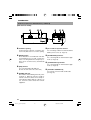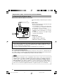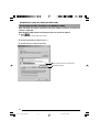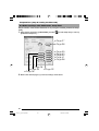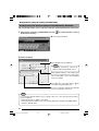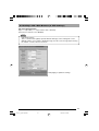
1
V.NETWORKS
Model
VN-C10
INSTRUCTIONS
For Customer Use:
Enter below the Serial No. which is
located on the body. Retain this
information for future reference.
Model No.
VN-C10
Serial No.
LWT0095-001A
VN-C10_E_01-43.pm65e
1
08/01/03, 9:12 AM
IMPORTANT SAFEGUARDS
1.
2.
3.
4.
5.
6.
7.
8.
9.
10.
11.
12.
13.
14.
15.
16.
17.
18.
19.
Read all of these instructions.
Save these instructions for later use.
All warnings on the product and in the operating instructions should be adhered to.
Unplug this appliance system from the wall outlet before cleaning. Do not use liquid cleaners or aerosol
cleaners. Use a damp cloth for cleaning.
Do not use attachments not recommended by the appliance manufacturer as they may cause hazards.
Do not use this appliance near water - for example, near a bathtub, washbowl, kitchen sink, or laundry tub, in
a wet basement, or near a swimming pool, etc.
PORTABLE CART WARNING
Do not place this appliance on an unstable cart, stand, or table. The appliance may
(symbol provided by RETAC)
fall, causing serious injury to a child or adult, and serious damage to the appliance.
Use only with a cart or stand recommended by the manufacturer, or sold with the
appliance. Wall or shelf mounting should follow the manufacturer’s instructions, and
should use a mounting kit approved by the manufacturer. An appliance and cart
combination should be moved with care.
Quick stops, excessive force, and uneven surfaces may cause the appliance and
cart combination to overturn.
S3125A
Slots and openings in the cabinet and the back or bottom are pro-vided for ventilation, and to insure reliable operation of the appliance and to protect it from overheating, these openings must not be blocked or covered. The openings should never be blocked by placing
the appliance on a bed, sofa, rug, or other similar surface.
This appliance should never be placed near or over a radiator or heat register. This appliance should not be
placed in a built-in installation such as a bookcase unless proper ventilation is provided.
This appliance should be operated only from the type of power source indicated on the marking label. If you
are not sure of the type of power supplied to your home, consult your dealer or local power company. For
appliance designed to operate from battery power, refer to the operating instructions.
This appliance system is equipped with a 3-wire grounding type plug (a plug having a third (grounding) pin).
This plug will only fit into a grounding-type power outlet. This is a safety feature. If you are unable to insert the
plug into the outlet, contact your electrician to replace your obsolete outlet. Do not defeat the safety purpose
of the grounding plug.
For added protection for this product during a lightning storm, or when it is left unattended and unused for
long periods of time, unplug it form the wall outlet and disconnect the antenna or cable system. This will
prevent damage to the product due to lightning and power-line surges.
Do not allow anything to rest on the power cord. Do not locate this appliance where the cord will be abused by
persons walking on it.
Follow all warnings and instructions marked on the appliance.
Do not overload wall outlets and extension cords as this can result in fire or electric shock.
Never push objects of any kind into this appliance through cabinet slots as they may touch dangerous voltage
points or short out parts that could result in a fire or electric shock. Never spill liquid of any kind on the
appliance.
Do not attempt to service this appliance yourself as opening or removing covers may expose you to dangerous voltage or other hazards. Refer all servicing to qualified service personnel.
Unplug this appliance from the wall outlet and refer servicing to qualified service personnel under the following conditions:
a. When the power cord or plug is damaged or frayed.
b. If liquid has been spilled into the appliance.
c. If the appliance has been exposed to rain or water.
d. If the appliance does not operate normally by following the operating instructions. Adjust only those controls that are covered by the operating instructions as improper adjustment of other controls may result in
damage and will often require extensive work by a qualified technician to restore the appliance to normal
operation.
e. If the appliance has been dropped or the cabinet has been damaged.
f. When the appliance exhibits a distinct change in performance - this indicates a need for service.
When replacement parts are required, be sure the service technician has used replacement parts specified
by the manufacturer that have the same characteristics as the original part. Unauthorized substitutions may
result in fire, electric shock, or other hazards.
Upon completion of any service or repairs to this appliance, ask the service technician to perform routine
safety checks to determine that the appliance is in safe operating condition.
2
VN-C10_E_01-43.pm65e
2
08/01/03, 9:12 AM
Safety Precautions
FOR USA AND CANADA
Due to design modifications, data given in this
instruction book are subject to possible change
without prior notice.
CAUTION
RISK OF ELECTRIC SHOCK
DO NOT OPEN
CAUTION:TO REDUCE THE RISK OF ELECTRIC
SHOCK. DO NOT REMOVE COVER (OR
BACK). NO USER-SERVICEABLE PARTS
INSIDE.REFER
SERVICING
TO
QUALIFIED SERVICE PERSONNEL.
The lightning flash wish arrowhead
symbol, within an equilateral triangle is
intended to alert the user to the presence of uninsulated "dangerous voltage" within the product's enclosure that
may be of sufficient magnitude to constitute a risk of electric shock to persons.
The exclamation point within an equilateral triangle is intended to alert the
user to the presence of important operating and maintenance (servicing)
instructions in the literature accompanying the appliance.
Information for USA
This device complies with part 15 of the FCC Rules.
Changes or modifications not approved by JVC could
void the user’s authority to operate the equipment.
This equipment has been tested and found to comply
with the limits for a Class A digital device, pursuant
to Part 15 of the FCC Rules. These limits are
designed to provide reasonable protection against
harmful interference when the equipment is operated
in a commercial environment. This equipment
generates, uses, and can radiate radio frequency
energy and, if not installed and used in accordance
with the instruction manual, may cause harmful
interference to radio communications. Operation of
this equipment in a residential area is likely to cause
harmful interference in which case the user will be
required to correct the interference at his own
expense.
WARNING:
TO REDUCE THE RISK OF FIRE OR
ELECTRIC SHOCK, DO NOT
EXPOSE THIS APPLIANCE TO RAIN
OR MOISTURE.
AVERTISSEMENT:
POUR EVITER LES RISQUES
D’INCENDIE OU D’ELECTROCUTION, NE PAS EXPOSER
L’APPAREIL A L’HUMIDITE OU A LA
PLUIE.
INFORMATION (FOR CANADA)
RENSEIGNEMENT (POUR CANADA)
This Class A digital apparatus complies with
Canadian ICES-003.
Cet appareil numérique de la Class A est
conforme á la norme NMB-003 du Canada.
Information for Europe
Warning:
This is a class A product. In a domestic environment
this product may cause radio interference in which
case the user may be required to take adequate
measures.
This device complies with Part 15 of the FCC Rules.
Operation is subject to the following two conditions:
(1) This device may not cause harmful interference,
and (2) this device must accept any interference
received, including interference that may cause
undesired operation.
3
VN-C10_E_01-43.pm65e
3
08/01/03, 9:12 AM
Thank you for purchasing this product.
(These instructions are for VN-C10U.)
Before beginning to operate this unit, please read the instruction manual carefully in
order to make sure that the best possible performance is obtained.
Contents
Introduction
Contents ................................................................................................. 4
Features ................................................................................................. 6
Items Included ........................................................................................ 6
Required Operating Environment ........................................................... 7
Upgrading the Application ...................................................................... 7
Operating Precautions ........................................................................... 8
Controls, Connectors and Indicators ...................................................... 9
Preparations
Connection Examples .......................................................................... 11
Preparation Procedure ......................................................................... 12
Step 1 Connection and Installation
1-1 Attaching a Lens ....................................................................... 13
1-2 Connecting the Power Cord ...................................................... 14
1-3 Connecting a LAN Cable ........................................................... 15
1-4 Connecting the Alarm I/O Terminals .......................................... 16
1-5 Installing the Camera ................................................................ 18
Step 2 Setting the Network
2-1 Installing the Software ............................................................... 19
2-2 Setting the PC’s IP Address for Windows XP ............................ 20
Setting the PC’s IP Address for Windows 2000 ......................... 22
2-3 Setting the IP Address for VN-C10 with V.Networks
Setup Tool ................................................................................. 24
2-4 Other Settings with V.Networks Setup Tool ............................... 26
1 Password Setting .................................................................... 27
2 Alarm Setting .......................................................................... 28
3 Motion Detection Setting ......................................................... 30
4 Recording Setting ................................................................... 32
5 FTP Client Setting ................................................................... 34
6 Multicast .................................................................................. 36
7 Compression Format .............................................................. 38
8 Memory Capacity .................................................................... 38
9 Web ......................................................................................... 39
10 FTP Server ............................................................................. 40
11 Time Setting ............................................................................ 41
2-5 Registering the Connected Camera with V.Networks Controller .......... 42
Step 3 Adjusting the Camera
3-1 Back-focus Adjustment .............................................................. 43
4
VN-C10_E_01-43.pm65e
4
08/01/03, 9:12 AM
Operations
(V.Networks
Controller)
Step 4 Setting with V.Networks Controller
4-1 Starting Up V.Networks Controller ............................................. 44
4-2 Function Settings with V.Networks Controller ............................ 45
4-3 Motion Detection Standby ......................................................... 46
4-4 Image Size and Inversion .......................................................... 47
4-5 Setting the Image Quality .......................................................... 48
4-6 Frame Rate ............................................................................... 50
4-7 Alarm Setting ............................................................................. 51
4-8 Time Stamp ............................................................................... 53
4-9 Changing the Registered Information ........................................ 54
Step 5 Operations with V.Networks Controller
5-1 Operations with V.Networks Controller ...................................... 55
5-2 Record/Stop .............................................................................. 56
5-3 Playback .................................................................................... 57
5-4 Other Instructions on Record and Playback .............................. 59
5-5 Snapshot ................................................................................... 60
Operations
(Web Browser)
Step 6 Operations with a Web Browser
6-1 Required Operating Environment .............................................. 61
6-2 Access Authorization ................................................................. 62
6-3 Starting Up the Web Browser .................................................... 63
6-4 Settings with a Web Browser ..................................................... 64
1 Other Settings ........................................................................... 65
2 Image Settings .......................................................................... 68
3 View Settings ............................................................................. 69
4 Alarm Settings ........................................................................... 70
5 FTP Settings ............................................................................. 71
6-5 Viewing Still Images .................................................................. 73
6-6 Viewing Moving Images ............................................................ 74
6-7 VN-C10 Image Link ................................................................... 75
Others
Troubleshooting ................................................................................. 76
Specifications ..................................................................................... 77
External Dimensions ......................................................................... 77
5
VN-C10_E_01-43.pm65e
5
08/01/03, 9:12 AM
Introduction
Features
• VN-C10 uses a 1/3-inch CCD with 380,000 pixels, enabling monitoring of high quality images.
• For the compression method, in addition to the standard JPEG, VN-C10 supports MPEG4 for a
wide range of bit rates.
• Equipped with an image recording function by motion detection and alarm input.
• VN-C10 has a design similar to other CCTV monitoring cameras, allowing peripheral equipment
for such cameras to be also used for VN-C10.
• With a built-in Web server, VN-C10 supports Internet Explorer and Netscape.
• Multicast function. (Only for JPEG)
Items Included
CD-ROM
(The Instruction Manual inside)
Read Me First
Warranty Card
Service Information Card
How to Use This Manual
Characters and Symbols used in this Manual
Caution
Note
☞
Operational points special attention should be paid to, because of, for example,
danger involved.
Functional or operational tips.
Pages or items to refer to.
❈ In no case, shall JVC be held liable for any loss or damage to the customer or for any claim
from any third party arising from using this software.
For the purpose of improving the product, the software specifications are subject to change
without prior notice.
The product names that appear in this document are brand names or registered trademarks
of each relevant company. Marks and symbols such as ™, ® and © do not appear in this
document.
6
VN-C10_E_01-43.pm65e
6
08/01/03, 9:12 AM
Required Operating Environment
PC Specifications
OS
CPU
Memory Capacity
Hard Disk Space
Display/Video Card
: Windows 2000 (Service Pack 1 or higher)
Windows XP Home Edition
Windows XP Professional
: Pentium III 500 MHz or higher (1 GHz or higher recommended)
: 128 MB or more
: 20 MB or more
: 1024 X 768 pixels or more, True Color (24 bits or 32 bits)
LAN Specifications
• 10 BASE-T/100 BASE-TX network connected with IEEE802.3 hubs.
Note
The PC specifications above are only for a reference purpose. They are not meant to guarantee a smooth operation of the application software. Depending on the usage of the PC, there
may be cases where problems occur even if the PC satisfies the technical requirements.
Caution
If the OS specifications of the PC to be used are higher, they precede those described above.
Upgrading the Application
For information on upgrading the application, visit the following website.
http://www.jvc-victor.co.jp/english/pro/vnetworks/index-e.html
7
VN-C10_E_01-43.pm65e
7
08/01/03, 9:12 AM
Introduction
Operating Precautions
● VN-C10 is designed for indoor use. For outdoor use, prepare a proper housing to cover and
protect the camera.
● The product should not be installed or used in the following locations.
• Locations subject to rain or water.
• Locations with hot air or oil vapors such as in kitchens, etc.
• Locations where the allowed ambient temperature (0 °C to 40 °C) is exceeded.
• Locations exposed to X-ray radiation or where strong electrical or magnetic waves are generated.
• Locations where corrosive gas is generated.
• Locations with vibrations.
• Locations with excessive dust.
● If VN-C10 and the cables connected to VN-C10 are installed at a location where strong electrical
or magnetic waves are generated, near a radio, TV set, transformer, motor etc., the quality of
image and color may be affected.
● If a high-intensity object (such as a lamp) is shot, the image on the screen may have vertical lines
(smear) or blur (blooming) at its periphery. This is a characteristic of the CCD, and is not a defect.
● Clean the unit with the power turned off. Use a soft cloth like cotton flannel to wipe out dirt. Do not
use paint thinner or benzine as a cleaning agent as this may cause melting or tarnishing of the
unit surface. If dirt is persistent, use a cloth soaked with water-diluted mild detergent and then
wipe it with a dry cloth.
● Because the cable holders of the terminals could come loose, perform cable connection carefully
and securely.
● Insufficient dissipation of heat from the unit may cause damage. Use the unit at a well-ventilated
location. In particular, do not block the unit’s cooling-fan ventilation opening.
● In a narrowband environment, for example, of dial-up connection, smooth running of MPEG4
images cannot be obtained. This is due to the product design, therefore not a defect.
● When this product is installed in an NAT environment, MPEG4 images cannot be viewed. This is
due to the product design, therefore not a defect. (This product uses a network protocol called
RTP for transmitting MPEG4 images. Generally, an NAT router cannot carry out NAT translation
of RTP packets properly.)
● Certain hubs and switches equipped with SNMP functions have a broadcast or multicast control
function. If the function is enabled, multicast images created by this product may not be viewed
properly.
● To save electricity, turn off the power to the system when not in use.
● As local recording images are saved to the volatile memory of the product, the images are
deleted if the power is turned off. (☞Page 33)
8
VN-C10_E_01-43.pm65e
8
08/01/03, 9:12 AM
Controls, Connectors and Indicators
(Front, top and side views)
2
1
3
4
5
7
1 Lens mount
8
6
5 Screw hole (1/4-20UNC)
The mount for attaching a lens. Either a Cmount or a CS-mount lens can be used.
2 Back-focus adjustment ring
The ring for adjusting back-focus and changing the mount method. For adjusting back-focus or changing the mount method, loosen
the back-focus locking screw (3) by turning it
counterclockwise and, after the operation, fix
it by turning it clockwise. At the factory, VNC10 is optimized for attaching a CS mount
lens.
For attaching the camera to
a fixer or a pan/tilt unit. The
screw length must not exceed 7 mm. If a longer screw
is used, the internal parts of
the camera may be damaged.
MAX.
7 mm
6 Fall-preventive holes
For installing the camera securely, use these
holes to prevent it from falling off.
7 Screws for the bracket (x 2: M2.6 X 6 mm)
3 [BF LOCK] locking screw
This serves to fix the back focus-adjustment
ring.
4 Bracket for camera mounting.
At the factory, the bracket is attached on the
bottom of the camera. According to the installation condition, this can be attached at the
top. Use the screws (7) for attaching the
bracket to the camera.
Screws of the length of 6 mm should be used.
A longer screw may damage the internal parts.
8 [MAC address]
Physical address unique to the unit. Cannot
be changed.
9
VN-C10_E_01-43.pm65e
9
08/01/03, 9:13 AM
Introduction
Controls, Connectors and Indicators (continued)
(Side and rear views)
#
2
G
2
1 OUT COM
OUTPUT
DC12V
AC24V
1
$ %
INPUT
0 !
CLASS 2 ONLY For USA
ISOLATED POWER ONLY
For EUROPE
9
ALARM
RESET
@
IRIS
PUSH
POWER
10BASE-T/100BASE-TX
DO NOT CONNECT TO THE
TELEPHONE NETWORK
For USA
^
9
Ventilation opening
For the internal cooling fan. Install the camera in a way that does not cover the opening.
#
[DC 12 V/AC 24 V] Power terminal
For connecting to a DC 12 V or AC 24 V, 50 Hz/
60 Hz, power source. (☞ Page 14)
0
[RESET] button
Press this button to reset VN-C10. If this button is held down for 2 seconds or longer, the
values set with [V.Networks Setup Tool] return to those set at the factory, and VN-C10
restarts.
$
[ALARM INPUT] terminals
For connecting with an external alarm equipment. (☞ Page 16)
%
[ALARM OUTPUT] terminals
For connecting with an external alarm equipment. (☞ Page 16)
^
[10 BASE-T/100 BASE-TX]
For network connection with a LAN cable.
(☞ Page 15)
!
@
[IRIS] terminal
For connecting with a DC IRIS lens.
(A video iris lens cannot be connected.)
[POWER] indicator
This indicator starts blinking when the power
is turned on. When the camera is ready for
network connection, this becomes steady on.
If the indicator blinks while the camera is in
use, check the camera and/or the network
equipment.
10
VN-C10_E_01-43.pm65e
10
08/01/03, 9:13 AM
Preparations
Connection Examples
LAN Connection
MAC address
ALC LEVEL
Av Pk L
H
VN-C10
BF LOCK
LAN
PC
MAC address
ALC LEVEL
Av Pk L
H
VN-C10
BF LOCK
Network Connection
MAC address
ALC LEVEL
Av Pk L
H
VN-C10
BF LOCK
MAC address
ALC LEVEL
Av Pk L
H
VN-C10
LAN
BF LOCK
INTERNET
FTP Server
PC
Images are automatically
updated at a regular interval.
PC
Peer-to-Peer Connection
H
Av Pk L
ALC LEVEL
VN-C10
MAC address
BF LOCK
PC
11
VN-C10_E_01-43.pm65e
11
08/01/03, 9:13 AM
Preparations
Preparation Procedure
Set the camera in the following procedure.
Step 1 Connection and Installation
Attach a lens and connect the power cable, a LAN cable and an alarm etc.
Then, install the camera to a fixer, etc. Fix a wire securely for preventing the
☞ Page 13
camera from falling off.
Step 2 Setting the Network
Install the software [V.Networks Controller], and set the network for the PC
and VN-C10. Also perform the setting with [V.Networks Setup Tool] and regis-
☞ Page 19
tration of the connected camera with [V.Networks Controller].
❈ If multiple PCs are in use, first turn on the power for one PC and proceed to 2-4
Other Settings with V.Networks Setup Tool. Only then, turn on the power to a second PC and go on to 2-4. Repeat the procedure for other PCs. (☞ Page 14)
Step 3 Adjusting the Camera
☞ Page 43
Adjust the back-focus while checking images.
Step 4 Setting with V.Networks Controller
Set image quality and alarm, etc. by using [V.Networks Controller] which has
been installed.
☞ Page 44
Step 5 Operations with V.Networks Controller
Now the camera is ready for recording and playback, etc. with [V.Networks
Controller].
Step 6 Operations with a Web Browser
☞ Page 61
The camera is ready for Web operations.
12
VN-C10_E_01-43.pm65e
12
☞ Page 55
08/01/03, 9:13 AM
Preparations (Step 1 Connection and Installation)
1-1 Attaching a Lens
Attach a lens in the following procedure.
1. Before
(a)
attaching a lens, check the mount
method of the lens.
VN-C10 is set for CS-mount at the factory. For
attaching a C-mount lens, loosen the backfocus locking screw using a screwdriver and
turn the back-focus adjustment ring to change
the mount method accordingly with a finger
or a pointed tool like a screwdriver.
To attach a lens, observe the length shown
as (a). Do not use a lens with a length longer
than (a) as it may cause damage to the internal parts of the camera and proper lens attachment would not be possible.
F
(b)
2.
RESET
Lens
Flange-back distance (b)
Length (a)
C-mount lens
17.526mm
10 mm max.
CS-mount lens
12.5mm
5.5 mm max.
2. Attach the lens to the camera securely by turn-
IRIS
ing it clockwise.
3.
1 3
3. In the case of a DC IRIS lens, connect the
lens cable to the socket while examining the
pin arrangement.
2 4
4-Pin Plug
Lens
Pin No.
1
1
2
3
4
3
DC IRIS Lens
(Without a built-in EE amplifier)
Damping d
Damping e
Driving e
Driving d
4
2
13
VN-C10_E_01-43.pm65e
13
08/01/03, 9:13 AM
Preparations (Step 1 Connection and Installation)
1-2 Connecting the Power Cord
Connect the camera to DC 12 V or AC 24 V.
The power indicator is lit when the power is turned
on.
G
2
1 OUT COM
OUTPUT
2
INPUT
DC12V
AC24V
1
CLASS 2 ONLY For USA
ISOLATED POWER ONLY
For EUROPE
To
Power
ALARM
PUSH
Power
indicator
lamp
POWER
Power Cord
• Do not connect the power cord to DC 12 V and
AC 24 V at the same time.
• Use a lug plate to securely connect the power
cord to the power terminals and avoid
misconnection or loose connection.
• For DC 12 V connection, ensure that the
polarities, positive and negative, are correctly
oriented.
• For DC 12 V connection, the ripple voltage
should not exceed 50 mV.
10BASE-T/100BASE-TX
For USA
DO NOT CONNECT TO THE
TELEPHONE NETWORK
Cable to Use
• Length: 30 m maximum
• UL1007, UL1015 or equivalent
• AWG #20 or equivalent, or higher
WARNING
Connect with the appropriate power-supply voltage.The rated voltage for VN-C10 is DC 12 V
or AC 24 V, 50 Hz/60 Hz. If a voltage exceeding the rating is supplied, malfunction, or in the
worst case, fuming or fire, may be caused.
For AC 24 V, ensure that the primary side is insulated with the secondary one.
For a system with multiple VN-C10s
In a system where more than one VN-C10 are used, turn on the power for a VN-C10 first and
proceed the setting to 2-4 Other Settings with V.Networks Setup Tool. Only then turn on the power for
a second one and go on to 2-4. Repeat the procedure for the other cameras.
Note
The IP address of VN-C10 is set to “198.168.0.2” at the factory. Proper access cannot be
established due to IP address redundancy if the power is turned on for multiple cameras at
one time under a single LAN environment. Do not turn on the power for multiple cameras
at the same time. If an IP address redundancy occurred, ensure that only one VN-C10 exists
on a single LAN environment and wait for some time (at least 10 minutes). Or turn off the
power once for all network equipment and turn it on again for proper access to VN-C10.
14
VN-C10_E_01-43.pm65e
14
08/01/03, 9:13 AM
1-3 Connecting a LAN Cable
G
2
• For hub connection
Use a straight cable.
1 OUT COM
OUTPUT
2
INPUT
DC12V
AC24V
1
CLASS 2 ONLY For USA
ISOLATED POWER ONLY
For EUROPE
Connect the camera to a hub or a PC by using a LAN cable.
ALARM
• For PC connection
Use a cross-over cable.
PUSH
Caution
POWER
10BASE-T/100BASE-TX
For USA
DO NOT CONNECT TO THE
TELEPHONE NETWORK
There are a few types of LAN board for
which a cross-over cable cannot be used.
Check the specifications of the LAN board
to be used before performing connection.
Note
For 100 BASE-TX, use a CAT-5 cable.
15
VN-C10_E_01-43.pm65e
15
08/01/03, 9:13 AM
Preparations (Step 1 Connection and Installation)
1-4 Connecting the Alarm I/O Terminals
G
1 OUT COM
OUTPUT
2
INPUT
2
AC24V
DC12V
1
CLASS 2 ONLY For USA
ISOLATED POWER ONLY
For EUROPE
Connect the alarm I/O terminals with external equipment such as a sensor, buzzer,
etc.
ALARM
PUSH
POWER
10BASE-T/100BASE-TX
Press the buttons for connecting or disconnecting cables as shown on the left.
Cable Specifications
50 m max.
UL1007, UL1015 or equivalent
AWG #22 to AWG #18 or equivalent
DO NOT CONNECT TO THE
TELEPHONE NETWORK
For USA
Caution
Due to external noise, the camera may not
work properly even if the length of the cable
is less than 50 m. If this occurs, use a
shielded cable or keep the cable away from
the noise source.
Push
Alarm Input Terminal
This terminal is for connecting with a sensor, infrared, door or metallic, or a manual
switch.
Sensor
Connection
Example 1
VN-C10
DC3.3V
R
VCC
Terminal 1 or 2
OUT
3.3V
Grounding
terminal
R
0.6mA
GND
Sensor
Connection
Example 2
(Alarm input equivalent circuit)
Input Requirements
• No-voltage relay “A-contact” input or NPN open
collector input
(A-contact: Contact is normally open and closes
when the alarm is turned on.)
• Active low level
• Latch/Momentary (at least 500 ms)
• Circuit current at low level: 0.6 mA
• Voltage applied at high level: 3.3 V
Relay, switch etc.
OUT
GND
16
VN-C10_E_01-43.pm65e
16
08/01/03, 9:13 AM
1-4 Connecting the Alarm I/O Terminals (continued)
Alarm Output Terminal
This terminal is for connecting with an alarm annunciator such as an indicator, a
lamp or a buzzer.
Annunciator
Output Requirements
Connection
Example 1
VN-C10
Output
terminal
MAX
300 mA
COM
terminal
Grounding
terminal
(Alarm output equivalent circuit)
DC 12 V
R
IN
MAX
12 V
COM
GND
Annunciator
Connection
Example 2
R
DC
12 V
IN
Buzzer, lamp, LED etc.
• Equivalent to NPN open collector output
(The output logic is set with [V.Networks Setup
Tool.])
• Allowed applied voltage: DC 12 V max.
• Allowed input current: 300 mA
• Momentary output: 2 to 5000 ms
(The duration is set with [V.Networks Setup
Tool.])
Caution
Connect the VN-C10 grounding terminal to
the one of the annunciator.
COM
GND
Annunciator
Connection
Example 3
R
DC
12 V
Buzzer, lamp, LED etc.
17
VN-C10_E_01-43.pm65e
17
08/01/03, 9:13 AM
Preparations (Step 1 Connection and Installation)
1-5 Installing the Camera
Fall-Preventive wire
For attaching the camera to a fixer or a rotating platform, use the screw hole of the
mounting bracket.
Camera mounting
screw hole
Camera-mounting bracket
Fall-preventive holes Screws for the bracket
[x 2: M2.6 x 6 mm]
Caution
● The length of the screw for
mounting the camera must
not exceed 7 mm. Do not
use a longer screw as it MAX.
may damage the internal 7 mm
parts of the camera.
● In the factory setting, the
bracket is attached on the
top of the camera. For attaching it at the
bottom, remove the two screws fixing the
bracket.
Securing wire
M2.6 x 4 mm
Caution
For fixing the bracket, screws of the length
of 6 mm should be used. Do not use a
longer screw as it may damage the internal
parts of the camera.
4 mm
2 mm
[Fall Prevention]
WARNING
• Special care is required if the camera is installed on a wall or ceiling. You should not attempt
to install it by yourself as it may cause injury or an accident. This installation work should be
carried out only by qualified and experienced personnel.
• When the camera is attached to a fixer or a pan/tilt unit, use the holes for fall prevention to
secure it.
• To prevent the camera from falling off, secure it to a secure and stable structure such as a
ceiling slab or a channel by using a wire.
• Ensure that the length, strength, routing and material (insulation) of the securing wire to be
used are appropriate.
• To attach the securing wire, use the black screw on the top side of the camera.
• For fixing the wire, a screw of M2.6 X 4mm should be used. Do not use a longer screw as it
may damage the internal parts of the camera.
18
VN-C10_E_01-43.pm65e
18
08/01/03, 9:13 AM
Preparations (Step 2 Setting the Network)
2-1 Installing the Software
For operating VN-C10, install the software from the CD-ROM, which is supplied with
~~~~~~~~~~~~~~~
the camera in the following procedure.
Installing V.Networks Controller
1. Select [Setup.exe] found in the [JVC] folder.
2. Proceed by following the instructions shown on the screen.
3. If the installation is successfully executed, the [V.Networks] icon is created in [Programs] of the
Windows [Start] menu.
[vn-c10u Controller] is displayed in [V.Networks].
Installing V.Networks Setup Tool
1. Open the [JVC] folder and then the “setup” folder inside. Select [Setup.exe].
2. Proceed by following the instructions shown on the screen.
3. If the installation is successfully executed, the [V.Networks] icon is created in [Programs] of the
Windows [Start] menu.
[vn-c10u Setup Tool] is displayed in [V.Networks].
Installing DirectX 8.1 and Codec
[DirectX 8.1] and ISO MPEG4 Codec are required for viewing MPEG4 images with VN-C10. If the
version currently installed in the PC is older, install the version 8.1 by following the procedure below.
Installing Codec
Select [WMPCD8.exe] and install Codec by following the instructions shown on the screen.
Installing DirectX 8.1
1. Click [Start] and select [Run]. And enter [dxdiag] in the box and click [OK].
2. If the version is older, select [DX81NTeng.exe] and follow the instructions on the screen.
19
VN-C10_E_01-43.pm65e
19
08/01/03, 9:13 AM
Preparations (Step 2 Setting the Network)
2-2 Setting the PC’s IP Address for Windows XP
After attaching the camera, proceed to set the IP address of the PC by which the
camera is operated.
With Windows XP, follow the procedure below to set the IP address.
(For Windows 2000, ☞ Page 22)
Note
Under a DHCP environment and also if the IP address to be allotted to [V.Networks] is already
known, skip 2-2 [Setting the PC’s IP Address].
1. Click
.
• Right-click [My Network] and select [Properties].
2. Select the network connected to the PC by which VN-C10 is operated.
• Right-click to select [Properties].
Ensure that [Client for Microsoft Networks]
is selected
.
Note
If either [Client for Microsoft Networks]
or [Internet Protocol (TCP/IP)] is not
displayed, select [Install ...].
20
VN-C10_E_01-43.pm65e
20
08/01/03, 9:13 AM
2-2 Setting the PC’s IP Address for Windows XP (continued)
3. Select [Internet Protocol (TCP/IP)] and click [Properties].
Select [Internet Protocol (TCP/IP)].
Click [Properties].
4. Select [Use the following IP address] to set [IP Address] and [Subnet Mask] and then click
.
Select [Use the following IP address].
Set [IP Address] to “192.168.0.3.”
Note
● Before changing the IP address,
note down the original address.
● Do not use the same IP address
elsewhere in this network environment.
Set [Subnet Mask] to an appropriate value
according to the operating environment.
Ask the network administrator if necessary.
Click
5. Click
.
in [Local Area Connection Properties].
21
VN-C10_E_01-43.pm65e
21
08/01/03, 9:13 AM
Preparations (Step 2 Setting the Network)
2-2 Setting the PC’s IP Address for Windows 2000
After attaching the camera, proceed to set the IP address of the PC by which the
camera is operated.
With Windows 2000, follow the procedure below to set the IP address.
1. Click
.
Select [Settings] and click [Control Panel].
2. Double-click [Network and Dial-up Co...].
3. Double-click [Local Area Connection].
Select [Internet Protocol (TCP/IP)].
Click [Properties].
22
VN-C10_E_01-43.pm65e
22
08/01/03, 9:13 AM
2-2 Setting the PC’s IP Address for Windows 2000 (continued)
4. Click [IP Address] in [TCP/IP properties].
Select [Use the following IP Address].
Set the IP address to “192.168.0.3.”
Set [Subnet mask] to an appropriate value
according to the operating environment. Ask
the network administrator if necessary.
5. Click
.
23
VN-C10_E_01-43.pm65e
23
08/01/03, 9:13 AM
Preparations (Step 2 Setting the Network)
2-3 Setting the IP Address for VN-C10 with V.Networks Setup Tool
Set the IP address for VN-C10 by using the installed [V.Networks Setup Tool].
(With this [V.Networks Setup tool] only VN-C10, not other models, can be connected.)
Caution
● After the power for VN-C10 is turned on, there will be about 20 seconds until VN-C10 becomes ready to be connected with the PC. This is not a defect.
● At the factory, DHCP is set enabled for VN-C10.
● About the DHCP function
JVC does not recommend operating VN-C10 with this function enabled because a different
IP address may be assigned upon the renewal of the leasing contract. The DHCP function
of VN-C10 is designed for simplifying the installation and setting procedures.
Note
For connecting VN-C10 with the factory settings, either one of the environments described
below is required.
● Environment where no DHCP server exists.
● Environment where a DHCP server exists, which clearly defines the allotted IP address and
MAC address.
1. Select [Start], [Programs], [V.NETWORKS] and then
[vn-c10u Setup Tool] to start up
[V.Networks Setup Tool].
Enter the IP address of the camera to be
connected to [Connection IP Address].
The IP address is set to 192.168.0.2 at
the factory.
Click
.
Note
Click [Search] to see the IP address of the connected camera.
The [V.Networks Search] screen is displayed.
To star t search, click [Search].
[V.Networks IP Address List] is displayed.
● [TimeOut] is for setting the time for searching (0 to 30 seconds).
If no IP address is displayed by searching, change the value to a longer one and then search again.
● If [V.Networks] on LAN has a different subnet from that of the PC, connection cannot be
established even if the IP address of the camera can be searched and found. Reconnect the
camera after changing the IP address of the PC accordingly.
24
VN-C10_E_01-43.pm65e
24
08/01/03, 9:13 AM
2-3 Setting the IP Address for VN-C10 with V.Networks Setup Tool (continued)
2. Confirm the settings.
Select whether to use DHCP.
Note
● With DHCP selected, the IP address of the DHCP server etc. can
be checked.
Change the IP address to the one alloted,
or approved, by the network administrator.
Set the subnet mask to an appropriate
value according to the operating environment. Ask the network administrator if necessary.
Click
For other settings, ☞ next page
3. Click
.
[V.Networks ID] works as an identification code set to VN-C10. Only alphanumeric characters can be used. This ID
does not directly affect the operation by
the user. Normally, the ID should be set
as “CAM00001,” “CAM00002” etc.
.
Click
to update the values.
Note
A new IP address becomes effective
when VN-C10 is automatically reset.
4. Start up [V.Networks Controller]. (☞Page 42)
Note
In a system where more than one VN-C10 are used, turn on the power for a VN-C10 first and
proceed the setting to 2-4 Other Settings with V.Networks Setup Tool. Only then turn on the
power for a second one and go on to 2-4. Repeat the procedure for the other cameras.
25
VN-C10_E_01-43.pm65e
25
08/01/03, 9:13 AM
Preparations (Step 2 Setting the Network)
2-4 Other Settings with V.Networks Setup Tool
Set passwords, alarm, motion detection etc. by using the installed [V.Networks Setup
Tool].
1. Select [Start], [Programs], [V.NETWORKS] and then
[vn-c10u Setup Tool] to start up
[V.Networks Setup Tool].
☞Page 27
☞Page 38
☞Page 39
☞Page 40
☞Page 34
☞Page 41
☞Page 38
☞Page 28
☞Page 32
☞Page 30
☞Page 36
2. Refer to the relevant pages (☞) for these settings shown above.
26
VN-C10_E_01-43.pm65e
26
08/01/03, 9:13 AM
2-4 Other Settings with V.Networks Setup Tool [1. Password Setting]
VN-C10 is equipped with an access protection (security) function that, by setting
passwords, regulates users of the connected PC.
Setting and cancellation of passwords can be performed with [V.Networks Setup
Tool].
According to access right (authorization) levels, up to 3 passwords (user, operator and administrator)
can be set.
Access Right Level
User
Operator
Administrator
Allowed Actions
Only viewing moving images
All operations with [V.Networks Controller]
All of the above and all settings with [V.Networks Setup Tool]
Note
Do not forget the passwords as they cannot be changed unless the current, and correct ones
are entered.
1. Start up [V.Networks Setup Tool] and select [User], [Operator] or [Administrator].
Enter a password to set password protection or change the password. Entered characters are displayed as asterisks (*).
• Enter the same password for both boxes.
• A password must be alphanumeric and
can be up to 8 characters.
Note
To cancel an existing password,
leave the password entry box blank
.
and click
.
Click
2.The following screen is displayed for confirmation.
Click
.
Note
● For a password-protected VN-C10, the password request screen appears.
● VN-C10 cannot be set up unless the correct administrator password is entered.
● The security level is highest for the administrator and lowest for the user. If password is set
only for lower security level(s), password protection is not effective.
27
VN-C10_E_01-43.pm65e
27
08/01/03, 9:13 AM
Preparations (Step 2 Setting the Network)
2-4 Other Settings with V.Networks Setup Tool [2. Alarm Setting]
This section describes alarm setting.
Alarm input is activated in the following cases.
• Input signals are received from an input terminal located on the rear panel of the camera, [ALARM
INPUT 1] or [ALARM INPUT 2]. (☞ Page 16)
• Motion has been detected. (☞ Page 30)
Operation when alarm input is activated.
• Output signals are sent from the output terminal located on the rear panel of the camera, [ALARM
OUTPUT]. (☞ Page 17)
• Alarm information is reported to [V.Networks Controller.] (☞ Page 29)
• Alarm Images are recorded. (☞ Page 32)
1. Start up [V.Networks Setup Tool] and select [Alarm].
1
4
2
3
5
7
6
8
2. When the setting is complete, select [Apply] and then
.
28
VN-C10_E_01-43.pm65e
28
08/01/03, 9:13 AM
2-4 Other Settings with V.Networks Setup Tool [2. Alarm Setting] (continued)
1
2
3
4
Alarm 1
Select [ON] to convert signals input to the
[ALARM INPUT 1] terminal to [Alarm 1] signals.
If [Alarm Output] is selected, alarm signals are
sent to the [ALARM OUTPUT] terminal according to the output port setting.
Alarm 2
Select [ON] to convert signals input to the
[ALARM INPUT 2] terminal to [Alarm 2] signals.
If [Alarm Output] is selected, alarm signals are
sent to the [ALARM OUTPUT] terminal according to the output port setting.
Motion Detection
Select [ON] for motion within the set area to
be recognized as a cause for an alarm.
If [Alarm Output] is selected, alarm signals are
sent to the [ALARM OUTPUT] terminal according to the output port setting.
Relay Alarm
Select here to enable the alarm function, which
is activated when two alarms are successively
received within a certain period of time.
The sequence and interval of alarm input can
be set.
If [Alarm Output] is selected, alarm signals are
sent to the [ALARM OUTPUT] terminal according to the output port setting.
Note
• A second alarm input enables this relay
alarm function, and alarm will not be activated for this second input.
• Unless the alarm output is enabled, this
function is not activated even if [Alarm
Output] of the [Alarm Settings] screen is
selected.
5
Retry [1 to 3]
This function sets how many times an alarm
alert to [V.Networks Controller] is repeated (1
to 3).
Note
Depending on the LAN environment, alarm
alert might fail. If it fails, set the value to “3”.
In such a case, alarm by [V.Networks Controller] itself is set off only once.
6
Alarm force output
If [Output] is pressed, alarm signals are sent
to the [ALARM OUTPUT] terminal. This forced
output is used for checking the alarm function.
7
Out port setting
Enable this function to output alarm signals
to the [ALARM OUTPUT] terminal.
Using output values, set the polarity, high or
low, and output time (1 to 5000 ms) according to the equipment connected.
If initialization is set to start, the set alarm signal is output once when the power is turned
on.
List
Press here to show the IP addresses of the
PCs to which alarm input is reported. To delete an IP address, select the address and
press [Delete].
8
Note
• If more than 10 destinations are set, this
function is not activated.
29
VN-C10_E_01-43.pm65e
29
08/01/03, 9:13 AM
Preparations (Step 2 Setting the Network)
2-4 Other Settings with V.Networks Setup Tool [3. Motion Detection Setting]
This section describes the setting of the motion detection function which enables VN-C10 to
trigger an alarm when motion is detected in a specified area. Motion is monitored while being
compared to the reference image. The area within which the function is effective can be set in
the following procedure.
(This function cannot be set for MPEG4.)
1. Start up [V.Networks Setup Tool]. Select [Alarm] and then enable [Motion Detection Alarm].
(☞Page 28 [Alarm Setting])
2. Select [Motion Detect] of [V.Networks Setup Tool].
Select the desired monitoring area by clicking and holding down the left button of the
mouse and dragging it. The selected area
is displayed in yellow.
Click the right button of the mouse and,
while holding it down, drag the mouse to
cancel a monitoring area.
The area in which motion has been detected
is displayed in red.
The [Detail] button is used for more detailed
settings.
Note
● A selected area is only for reference. To ensure accuracy, perform operation check.
● One screen is divided in 300 (20x15) blocks. Adjust magnification of the lens so that the
monitoring area (object) covers more than one block.
Caution
The motion detection function is not designed to prevent burglary or fire. It may not function
properly depending on the condition of the object or settings described in this document. In no
case, shall JVC be liable for any accidents and/or damage caused.
30
VN-C10_E_01-43.pm65e
30
08/01/03, 9:13 AM
2-4 Other Settings with V.Networks Setup Tool [3. Motion Detection Setting] (continued)
3. Press [Detail] to display [Motion Detection Setting].
V.Networks General Setting
Refresh Interval
The reference image on which motion detection is based is refreshed at a regular interval. In a condition where the reference image changes, like outdoors, set a low value.
Note
With the interval set to “0 second,” the
reference image is automatically refreshed if a motion is not detected for
10 seconds.
Motion Distinction Interval
This is for setting the minimum duration of
time for which the object being monitored
must move to be recognized as “motion.” If
the object is slow moving, the time should be
longer to avoid detection errors.
Available MASK
Areas outside the one already set for motion
detection (displayed in yellow) can also be
selected.
Reference Image
For checking the reference image. The screen
below is displayed.
Refresh
Press this button to refresh the reference
image.
Parameters
Y Threshold
A smaller value allows motion detection even
if the difference of brightness with the reference image is insignificant.
%
Set to a smaller value if the moving object is
not large enough and cannot be detected.
Noise Filter
Set to a larger value to reduce noise in the
whole image.
Updates the reference image.
If this is selected, the reference image is automatically refreshed at a designated interval.
31
VN-C10_E_01-43.pm65e
31
08/01/03, 9:13 AM
Preparations (Step 2 Setting the Network)
2-4 Other Settings with V.Networks Setup Tool [4. Recording Setting]
This function records the image to the memory of VN-C10 when an alarm is activated.
(This cannot be set for MPEG4.)
• When an alarm is activated, image recording can be carried out in one of the following two ways.
One way, local recording, saves images to the VN-C10 memory, and the other records images with
[V.Networks Controller] and saves them to the PC hard disc drive, etc. (☞ Page 51)
1. Start up [V.Networks Setup Tool] and select [Recording].
To make new values effective, press [Apply] and then
.
Trigger Recording
For selecting the record starting trigger, the
alarm input signal to start local recording.
For setting the recording time. Up to 60
seconds can be set both before and after
an alarm input.
Caution
● If the value for before a trigger is set
to “0,” set a different value for after
the trigger. Both values cannot be set
to “0” at the same time.
● Because of the memory capacity of
VN-C10, the setting times before and
after a trigger and the actual maximum recording time are not the
same.
Example:
• If 160x120 (30 fps)/320x240 (15 fps)/
640x480 (5 fps) with a compression
rate of 2, the actual recording time is
5 to 0 and 30 to 35 seconds, before
and after a trigger respectively.
• For the maximum recording (30 before and 60 seconds after a trigger),
perform the setting as follows:
Image size
: 160x120
Frame rate
: 30 fps
Compression rate
:7
2. Frame Rate
For setting the frame rate for local recording,
select [Change the Recording FrameRate
during trigger recording] and set the frame
rate (30, 15, 10, 8, 7, 6, 5, 4, 3, 2 or 1). The
default value is 30 fps.
32
VN-C10_E_01-43.pm65e
32
08/01/03, 9:13 AM
2-4 Other Settings with V.Networks Setup Tool [4. Recording Setting] (continued)
3. Others
Set the recording action when the memory
capacity for recording has become full. One of
the following two can be selected. (The internal
memory capacity is 8 MB.)
• Stop recording until a free memory space for
recording is created.
• Delete files older than the designated number
of days.
• If the number of days is set to “0,” the files are
deleted, starting with the oldest one.
Note
Recording time
● While maximum recording time varies depending on the recording frame rate and image
size, recording may not be possible for a desired length of time because of other factors such
as the compression rate and the object quality.
Recording files
● A trigger-recording file is created each time a trigger occurs. Even if triggering keeps occurring and recording continues, only one file will be created for each trigger.
Caution
Saving images of local recording to the PC
As local recording images are saved to the VN-C10 volatile memory, the images are deleted if
the power is turned off.
With recording by [V.Networks Controller], with which images are saved to the PC hard disk
drive, etc., saved files can be retained even if the power is turned off.
For saving local recording images to the PC, follow the procedure below.
Select [Refer to Local Rec].
Select the file to save it to the PC.
Right-click the file to select [Download to
PC].
By selecting desired items in [Trigger] and also performing necessary settings for [Message], etc. in
[Alarm Setting], you can be certain whether or not local recording has already started. (☞ Page 51)
33
VN-C10_E_01-43.pm65e
33
08/01/03, 9:13 AM
Preparations (Step 2 Setting the Network)
2-4 Other Settings with V.Networks Setup Tool [5. FTP Client Setting]
VN-C10 is equipped with an FTP client function which regularly uploads still images
to an existing FTP server, thus enabling simultaneous image monitoring at many
places and by many people.
(This function cannot be set for MPEG4.)
1. Start up [V.Networks Setup Tool] and select [FTP Setting]. The [FTP Setting] screen is
displayed.
1
2
3
4
5
6
7
8
9
34
VN-C10_E_01-43.pm65e
34
08/01/03, 9:13 AM
2-4 Other Settings with V.Networks Setup Tool [5. FTP Client Setting] (continued)
1
FTP
To use the FTP function, select [Available].
2
User Name
Enter the user name to use for verification with
the FTP server. It can be “anonymous.”
3
Password
Enter the password to use for verification with
the FTP server. The password is displayed
as asterisks (*).
4
FTP Server IP Address
Enter the IP address of the upload destination
FTP server.
5
FTP Port
Enter the FTP port number of the upload
destination. This is normally set to “21.”
6
FTP Folder
Enter the folder name on the upload
destination FTP server. If this box is left blank,
images are uploaded to the default folder.
7
Upload Interval
Specify the upload interval at which images
are uploaded to the FTP server (0 to 84600
seconds).
If [Disconnect every time] is selected,
connection with the FTP server is cut after an
image was uploaded.
8
Error Recovery
(Connection error)
Specify a recovery action when an error
occurred for TCP connection or FTP
verification of VN-C10.
Retry forever
: Recovery attempt is
repeated until the
power for VN-C10 is
turned off.
❈min. Retry
: Recovery attempt is
repeated for a
specified period
(❈)1 to 600 minutes.
(Transfer error)
Select a recovery action when a transfer error
occurred in uploading an image.
FTP Disabled: The FTP function is automatically disabled.
Note
To enable the function again, select [Available] for [FTP].
9
Filename
*.jpg
: If this file type is selected,
uploading is performed with
the entered file name.
Note
Only one image file is stored in the FTP
server as files are overwritten with the latest one.
Time stamp : Files are uploaded with the
time of the built-in clock as their
file names.
Note
● Set the correct time in the [Time Setting] screen.
● All uploaded image files are stored in
the FTP server.
35
VN-C10_E_01-43.pm65e
35
08/01/03, 9:13 AM
Preparations (Step 2 Setting the Network)
2-4 Other Settings with V.Networks Setup Tool [6. Multicast]
Selecting [Multicast Mode] allows VN-C10 to send the same image data to multiple recipients
on the network at one time without lowering the frame rate.
• In a narrowband environment, for example, of dial-up connection, select [Unicast Mode].
• Multicast cannot be set for MPEG4.
1. Start up [V.Networks Setup Tool] and select [Multicast]. The [Multicast Setting] screen is
displayed.
Select [Multicast Mode].
Enter a multicast address to [Multicast
address].
Multicast
● A multicast address can be set from 225.0.0.0 through 239.255.255.255. Do not set the
same multicast address for different devices on the same system.
● To view VN-C10 images in the multicast mode through a router, an operating environment or
a router setting is required as follows:
1 The router supports IGMP Ver. 2 and is synchronized with the starting and stopping of
multicast transmission. And the route setting can be dynamically changed.
2 If the router does not support IGMP Ver. 2, a static route for multicast must be set to the
router.
36
VN-C10_E_01-43.pm65e
36
08/01/03, 9:13 AM
2-4 Other Settings with V.Networks Setup Tool [6. Multicast] (continued)
VN-C10 multicast addresses on the network can be searched.
1. Start up [V.Networks Setup Tool].
Select [Search].
Click [Search...].
2. The [V.Networks Search] screen is displayed.
Click [Multicast search].
3. The [Multi Address Search] screen is displayed.
To start search, click [Search].
4. The search result is displayed.
37
VN-C10_E_01-43.pm65e
37
08/01/03, 9:13 AM
Preparations (Step 2 Setting the Network)
2-4 Other Settings with V.Networks Setup Tool [7. Compression Format]
Either JPEG or MPEG4 can be selected as the image compression format.
1. Start up [V.Networks Setup Tool] and for the compression format, select JPEG or MPEG4.
For MPEG4, select [MPEG-4].
Set the frame rate for MPEG4 (30, 15 or
7.5).
For smoother display of images, set a
larger value.
Set the bit rate for MPEG4 (64 to 2048).
For a better image quality, set a larger
value.
Caution
In the MPEG4 mode with the frame rate set to 30 fps,image noise may appear momentarily
depending on the condition of the object. This is not a defect.
2-4 Other Settings with V.Networks Setup Tool [8. Memory Capacity]
Memory capacity can be checked.
1. Start up [V.Networks Setup Tool] and for the compression format, select [JPEG] or [MPEG4].
Check the free memory space. The
memory capacity of VN-C10 is 8000 kB.
38
VN-C10_E_01-43.pm65e
38
08/01/03, 9:13 AM
2-4 Other Settings with V.Networks Setup Tool [9. Web]
An HTML file can be set as the default page of the web browser.
1. Start up [V.Networks Setup Tool] and select [Web].
Select whether to enable the setting of the
HTTP default page. If [Available] is selected,
specify an html file for the default page.
Set the port number.
There are a few types of proxy server that
caches CGI and the above setting cannot be
properly done. In such a case, select [No
Cache].
Caution
● It is possible to enhance the level of security by changing the default port number (80) of VNC10 HTTP server (1 through 65535). With this number changed, it can be accessed with a
Web browser by entering “http://192.168.0.2:12345” or “http://192.168.0.2:12345/index-e.html”
(in the case of the port number, 12345). If you have forgotten the port number, refer to
[Setup Tool].
● The default page refers to the page displayed when the IP address is specified (for example,
“http://192.168.0.2/”) in a Web browser. Even with this function enabled, if the specified file
does not exist, the message, “404: Not Found” will be displayed when “http://192.168.0.2/” is
entered.
39
VN-C10_E_01-43.pm65e
39
08/01/03, 9:13 AM
Preparations (Step 2 Setting the Network)
2-4 Other Settings with V.Networks Setup Tool [10. FTP Server]
Using FTP client software, HTML pages, GIF and JPEG images can be uploaded.
1. Start up [V.Networks Setup Tool] and select [FTP Server].
Select whether to enable or disable the FTP server function.
Note
● The FTP server name is fixed to [Administrator] and also use the password for the administrator.
● For the FTP user area, approximately 300 kB are allotted.
● All uploaded folders are stored directly under the [user] folder. It can be accessed as in
“http://192.168.0.2/user/aaa.html” with a Web browser. (“192.168.0.2” denotes the VN-C10
IP address when “aaa.html” is refered to.)
● Folders cannot be created in the VN-C10 FTP server. Only uploading, deleting and renaming of files are possible.
40
VN-C10_E_01-43.pm65e
40
08/01/03, 9:13 AM
2-4 Other Settings with V.Networks Setup Tool [11. Time Setting]
This section describes how to set the standard time for VN-C10. NTP can be used
for this function.
1. Start up [V.Networks Setup Tool] and select [Time].
There are two ways to set the time, with or without NTP.
NTP is not used.
Set the date and time.
The time by the PC clock can be checked.
NTP is used.
Enter the IP address of the NTP server.
Set the time zone.
Set the interval at which the current time is
obtained from the NTP server.
Note
● An NTP server is required for the NTP setting.
● If the time setting is changed while local recording is in progress, the local recording time
may not be properly counted. Thus, recording for the specified seconds may not be obtained.
● We recommend using an FTP server. Without it, the time returns to the initial value, January
1, 1900, when the power is turned off. In a situation wherein an FTP server cannot be used,
set the time appropriately when the power is turned on again.
● With Windows XP Home Edition and Windows XP Professional, NTP sever functions become enabled when they are installed in the standard procedure.
● For Windows 2000, follow the procedure below to enable NTP server functions.
1. Set the value for the following registry to “1.” (The default value is “0.”)
HKEY_LOCAL_MACHINE\SYSTEM\CurrentControlSet\Services\W32Time\Parameters\LocalNTP
Registry editing is a highly risky operation.
Safety measures should be taken beforehand, e.g. creating registry backups. JVC shall not
be held liable for any loss caused by registry editing.
2. Restart the Windows Time Service.
This can be done by opening [Administrative Tools] in [Control Panel] and selecting [Services], [Windows Time] and [Windows Time Properties].
41
VN-C10_E_01-43.pm65e
41
08/01/03, 9:13 AM
Preparations (Step 2 Setting the Network)
2-5 Registering the Connected Camera with V.Networks Controller
The connected camera can be registered with the installed [V.Networks Controller].
1. Select [Start], [Programs], [V.NETWORKS] and then
[vn-c10u Controller] to start up
[V.Networks Controller].
Select [File] and [New].
2. [New] is displayed.
Enter 198.168.0.2 in [IP Address].
Note
In a DHCP environment, enter the IP
address allotted by the DHCP server.
Enter [V.Network Name], a name under which
the camera is registered. Use a name that is
easy to remember, such as the installation
location or number.
Recording files of the name given in
saved in a designated folder here.
are
You can set whether VN-C10 automatically
starts recording upon connection.
Note
For connecting VN-C10 with the factory settings, either one of the environments described
below is required.
• Environment where no DHCP server exists.
• Environment where a DHCP server, which clearly defines the IP address and MAC address
allotted to VN-C10, exists.
42
VN-C10_E_01-43.pm65e
42
08/01/03, 9:13 AM
Preparations (Step 3 Adjusting the Camera)
3-1 Back-focus Adjustment
At the factory, back-focus is set at the point for the widest range of use for
CS-mount. However, it is necessary to readjust back focus if a zoom or C-mount
lens is used or if focus cannot be attained using the focus ring of the lens. To
adjust, follow the procedures described below.
In order to adjust back-focus appropriately, use the iris adjustment function and an ND filter to release the lens iris before proceeding with the adjustment. (An ND filter acts to reduce the overall
amount of light entering the lens equally over all wavelengths.)
Back focus
adjustment ring
Tighten
Loosen
Back focus locking
screw (M2.6)
Lens focus ring
<For a fixed-focus lens>
If focus cannot be attained using the focus ring of
the lens, adjust the back-focus as follows.
1. Loosen the back-focus lock screw by turning
it counterclockwise with a Phillips screwdriver.
2. Aim the camera at the object or a spot of detail
somewhere away from the object while
checking the image on the PC screen.
3. Turn the focus ring to .
4. Turn the back-focus adjustment ring to
optimize the focus.
5. Tighten the back-focus lock screw securely by
turning it clockwise.
<For a zoom lens>
If the image gets out of focus when zoomed in/
out, adjust the camera as follows:
1. Loosen the back-focus locking screw by
turning it counterclockwise with a Phillips
screwdriver.
2. Aim the camera at the object or a spot of detail
somewhere away from the object while
checking the image on the PC screen.
3. Zoom in the lens and adjust the focus by
turning the focus ring.
4. Zoom out the lens and adjust the focus by
turning the focus ring.
5. Repeat steps 3 and 4 a few times.
6. Tighten the back-focus locking screw securely
by turning it clockwise.
43
VN-C10_E_01-43.pm65e
43
08/01/03, 9:13 AM
Operations (Step 4 Setting with V.Networks Controller)
4-1 Starting Up V.Networks Controller
With the installed Controller, camera images can be monitored. The settings for
recording, replay and frame rate etc. can also be performed.
1. Select [Start], [Programs], [V.NETWORKS] and then
[vn-c10u Controller] to start up
[V.Networks Controller].
In the pull down menu, select the camera
to connect.
Caution
After the power for VN-C10 is turned
on, there will be about 20 seconds until
VN-C10 becomes ready to be connected with the PC. This is not a defect.
Live images from the camera are displayed.
Note
• If a password has been set, enter the correct password.
• This [Controller] can be connected to VN-C1, VN-C2, VN-C3, VN-C30 (only for JPEG), VNA1 and VN-C10.
44
VN-C10_E_44-61.pm65e
44
08/01/03, 9:15 AM
4-2 Function Settings with V.Networks Controller
With [V.Networks Controller], settings for image size, alarm etc. can be performed.
12 3 4
1 File
3 Setting
New
: Creates a new file if
the camera is connected for the first
time.
Delete
: Deletes a file.
Motion Detect Standby
: For selecting the
camera for which
motion detection is
enabled.
: Exits “Controller.”
Exit
Quality
: Sets the compression
rate and image quality.
Framerate
: Sets the number of
frames transmitted
per second.
Alarm Reg
: If this is selected ,
alarm operation will
be enabled.
Alarm
: Alarm actions for
each alarm can be
set individually.
Time Stamp
: Sets display of the
date and time of file
saving.
: Changes information
on cameras not currently connected.
2 View
Image Size
Upside Down
: Sets the image display size.
JPEG : 640x480
320x240
160x120
MPEG4 : 320x240
160x120
Property
: Displays the image
inversely. This func- 4 Help
tion is used in the
About
case that the camera
is inversely installed.
(Not available for
MPEG4)
: For checking the version of [V.Networks
Controller].
45
VN-C10_E_44-61.pm65e
45
08/01/03, 9:16 AM
Operations (Step 4 Setting with V.Networks Controller)
4-3 Motion Detection Standby
With [V.Networks Controller] running, automatic connection will be activated upon
reception of motion detection alert from VN-C10.
1. Select [File] and then [Motion Detect Standby].
2. Select the camera.
Select the camera for which you wish to
enable the motion detection function.
Click
3. Click
.
.
46
VN-C10_E_44-61.pm65e
46
08/01/03, 9:16 AM
4-4 Image Size and Inversion
With [V.Networks Controller], it is possible to set the size of the moving image window
and invert the image.
1. Select [View].
2. Select an image size and whether or not to invert the image.
Note
With MPEG4, the following settings are
not available.
• 640x480
• Upside Down
Click
.
Note
Right-click on the moving image window to
change the settings. (This setting is not available for MPEG4.)
Set the image size.
Displays the MAC address, IP address,
model, firmware version.
If this is selected, the blocks for motion detection are displayed. The blocks where motion is detected will be displayed in red.
47
VN-C10_E_44-61.pm65e
47
08/01/03, 9:16 AM
Operations (Step 4 Setting with V.Networks Controller)
4-5 Setting the Image Quality
With [V.Networks Controller], settings for image quality such as the image
compression rate, white balance, etc., can be done.
1. Select [Setting] and [Quality].
2. Change the set values. (For functional description, ☞ next page)
1
4
2
5
3
6
7
3. Click
.
48
VN-C10_E_44-61.pm65e
48
08/01/03, 9:16 AM
4-5 Setting the Image Quality (continued)
1
Compression Rate
Sets the image compression rate. A lower
compression rate means a higher image
quality. However, with a reduced compression
rate, data volume also increases.
This setting is not available for MPEG4.
Value range: 1 to 7 (Set to “2” at the factory)
2
White Balance
Auto
: Automatically adjusts the white
balance, the standard for color
saturation. Factory set.
R gain
: To manually adjust the white balance toward more red intensity.
Value range: 0 to100
B gain
: To manually adjust the white balance toward more blue intensity.
Value range: 0 to100
3
4
5
AGC, AES, BLC
AGC
: Automatically adjusts the gain in
accordance with the brightness.
Factory Set.
AES
: Automatically adjusts the shutter
speed in accordance with the
brightness. Only for a manual iris
lens.
BLC
: Back light compensation. When
there is a bright light source in the
background of the object, VN-C10
adjusts the weighted zone.
Photo-metering Area
Shutter Speed
1/60
: Normal speed. Factory set.
1/100
: This reduces image flickers due
to fluorescent lighting in areas
where the commercial power frequency is 50 Hz.
Note
● AES cannot be turned on when AGC is
set to [OFF].
● AES cannot be turned on if the shutter
speed is set to [1/100].
● BLC cannot be turned on when AGC is
set to [OFF].
● Do not use AES with a DC IRIS lens. It
may cause flickering.
Saturation
Adjusts color saturation. A smaller value
makes colors less dense. Set to “25” at the
factory
6
Default
Returns all values, except that for iris level,
for image quality to those set at the factory.
7
Iris level
Brightness adjustment for a DC IRIS lens.
A smaller value makes images darker, closing
the iris.
49
VN-C10_E_44-61.pm65e
49
08/01/03, 9:16 AM
Operations (Step 4 Setting with V.Networks Controller)
4-6 Frame Rate
With [V.Networks Controller], it is possible to set the frame rate, the number of
image updates per second, for JPEG.
Frame rate setting with [V.Networks Controller] is possible only for JPEG.
Frame rate for MPEG4 can be set with [V.Networks Setup Tool]. (☞ Page 38)
1. Select [Setting] and [Framerate].
2. Set the frame rate in the [Frame Rate] screen.
Sets the maximum number of images per
minute that are sent from VN-C10. This value
is set to “15” at the factory.
Note
The actual number of frames received and displayed per second is affected by factors such as
the PC performance and the image compression rate as well as the LAN environment.
In the case of a LAN environment where multiple operations are being performed at one time
(particularly where the network traffic is always heavy), reduce the number of frames to be
transmitted.
Caution
Frame rate for local recording cannot be set with [V.Networks Controller]. It is only possible
with [V.Networks Setup Tool]. (☞ Page 32)
50
VN-C10_E_44-61.pm65e
50
08/01/03, 9:16 AM
4-7 Alarm Setting
With [V.Networks Controller], it is possible to set the action to be taken upon
reception of an alarm signal.
1. Select [Setting] and [Alarm Setting].
2. Change the set values. (For functional description, ☞ next page)
Settings are performed for [Motion Detection Alarm], [Alarm 1], [Alarm 2] and [Relay Alarm].
1
Text box
2
3
4
(With [Relay Alarm] selected, 1 and 2 cannot be set.)
3. When the settings are complete, click
.
51
VN-C10_E_44-61.pm65e
51
08/01/03, 9:16 AM
Operations (Step 4 Setting with V.Networks Controller)
4-7 Alarm Setting (continued)
1
Message
When an alarm is received, the message
entered into the text box is displayed. The
maximum number of characters that can be
entered is 100.
2 Recording
When an alarm is received, recording starts.
Non-Stop : Recording continues until the
Stop button is pressed.
Stop 1min : Recording stops after 1 minute.
3
Note
If a large Wave file (.wav) is selected, the
alarm operation may become slow depending on the PC performance.
4
Note
• The [Stop 1min] mode is for conserving
the hard disk space.
• In this mode, recording stops after 1
minute even if recording has already
started before the alarm input.
Playing wave file
When an alarm is received, a specified Wave
file is replayed. Press the [Browse] button to
specify a Wave file.
Execute application file
When an alarm is received, a specified
program is executed. Press the [Browse]
button to specify a program.
Note
Alarm Operation
The following settings are required for the operation of the alarm that has been set.
1. [Alarm Reg] is enabled in the [Setting] menu of the [V.Networks Controller.] (☞ Page 45)
2. Each alarm setting in [Alarm Setting] of [V.Networks Setup Tool] is enabled. (☞ Page 28)
Relay Alarm
When the relay alarm function is enabled, subsequent alarms will not be activated.
52
VN-C10_E_44-61.pm65e
52
08/01/03, 9:16 AM
4-8 Time Stamp
With [V.Networks Controller], the [Time Stamp] function can be set. This function
displays the date and time on the camera images, and the date and time are recorded.
1. Select [Setting] and [Time Stamp].
2. Proceed with the setting.
Select [Visible].
Select the display style in [Style].
“YYYY,” “MM,” and “DD” represent “year,”
“month” and “day” respectively.
“HH” represents “hour” while “MM,” “minute,”
“SS,” “second” and “mm,” “millisecond.”
Click [Font...] to select the font.
Set the text color in [TextColor].
Set the background color in [BackColor].
Click
.
Note
• With MPEG4, ,
and cannot be set.
• By left-clicking the mouse while holding down the [shift] key on the moving image or playback
window screen, the time stamp will appear where the mouse was clicked.
• Time stamp in the MPEG4 mode is shown in the title bar of the image window.
53
VN-C10_E_44-61.pm65e
53
08/01/03, 9:16 AM
Operations (Step 5 Operations with V.Networks Controller)
4-9 Changing the Registered Information
With [V.Networks Controller], registered information on camera connection etc. can
be changed.
1. Select [Setting] and [Property].
2. Proceed with the setting.
Change the camera.
Cannot be changed.
Set whether to start recording on
connection.
3. When complete, click
.
Caution
Information cannot be changed for a connected camera.
54
VN-C10_E_44-61.pm65e
54
08/01/03, 9:16 AM
5-1 Operations with V.Networks Controller
[V.Networks Controller] can be used to select the camera, record and playback the
camera images etc.
(The Controller screens are identical with those for other V.Networks models. Certain
functions are not available for VN-C10.)
1
6
Not available for VN-C10.
2 3 4 5
1 Camera
4 REC
Displays the name of the connected camera.
It is also possible to select the camera using
the
pull down menu.
2 PLAY
When this is selected, recording starts. The
recorded files are saved under the name
shown in 1. During recording, the display
[Recording in progress] appears in 1. The
display [REC] will also appear on the displayed
image.
Select the file saved in 4 and replay. Select
this button too for replaying a recorded file with
an alarm activated.
5 SNAPSHOT
Saves only one frame of the image being
3 STOP
displayed.
Stops recording.
6 SIZE
Reduces the size of the [V.Networks Controller]
screen. (See below.)
Reduced screen
1 Camera
Press here to enlarge.
55
VN-C10_E_44-61.pm65e
55
08/01/03, 9:16 AM
Operations (Step 5 Operations with V.Networks Controller)
5-2 Record/Stop
[V.Networks Controller] can be used to save camera images to a file.
1. Click the [REC] button.
Connected camera
(Files are saved under this name)
Recording format
[Record] display
2. 1.
(Moving image window)
[REC] display
2. Click the [STOP] button.
Recording stops. The [Recording] and [REC] displays disappear.
When the [Snapshot] button is clicked, one single frame of the image being displayed is recorded.
(☞ Page 60)
Note
• Refrain from attempting continuous recording for an extended period of time. Files recorded
over an extended time may not be replayed fully due to an insufficient memory space of the
PC.
• Do not change the record file name.
56
VN-C10_E_44-61.pm65e
56
08/01/03, 9:16 AM
5-3 Playback
For playback, select the file saved with the record function of [V.Network Controller].
The playback function cannot be effective while moving images are displayed.
1. Click the [PLAY] button.
[PLAY] button
2. Select the file you wish to replay from [Playback File] and click
. To replay a local
recording file, click [Refer to Local Rec.]. And select the file.
Press [Refer to Local Rec.] to select the file.
A file name is displayed as the time when recording started to the time when it ended.
Click
.
57
VN-C10_E_44-61.pm65e
57
08/01/03, 9:16 AM
Operations (Step 5 Operations with V.Networks Controller)
5-3 Playback (continued)
3. Click
.
4. [Playback] is displayed.
Slidebar
• Moves toward the right as the playback time
progresses.
• Can be dragged with the mouse.
[Stop] button
[Pause] button
[Play] button
58
VN-C10_E_44-61.pm65e
58
08/01/03, 9:16 AM
5-4 Other Instructions on Record and Playback
Record/Playback time
• Do not record or play a file that exceeds 2 GB with [V.Networks Controller]. With Windows
applications, data in excess of 2 GB cannot be randomly accessed.
Approximate recording time for 2 GB JPEG data (at 5 frames per second)
Image size
Data size per image
160 x 120
320 x 240
Approx. 5 kB
Approx. 15 kB
Approximate recording time
20 hours
6 hours
640 x 480
Approx. 50 kB
2 hours
Approximate recording time for 2 GB MPEG4 data
Bit rate
Approximate recording time
64 kB/s
384 kB/s
65 hours
10 hours
2048 kB/s
2 hours
59
VN-C10_E_44-61.pm65e
59
08/01/03, 9:16 AM
Operations (Step 5 Operations with V.Networks Controller)
5-5 Snapshot
With [V.Networks Controller], images being displayed or replayed can be saved as
still image files.
1. Click the [SnapShot] button.
Note
Snapshots are saved as JPEG files in
the JPEG mode and as BMP files in the
MPEG mode.
[SnapShot] button
2. The [Snap] screen appears.
Select [File] and [Save].
3. The [Save As] screen appears.
Specify the folder into which the file is saved.
Enter the file name.
Press [Save] to save a snapshot.
Note
Other viewer software
• Still-image files saved with VN-C10 can be viewed with general viewer software. However,
images inverted by VN-C10 will not be displayed as such. Also, image color may also be
different.
60
VN-C10_E_44-61.pm65e
60
08/01/03, 9:16 AM
Operations (Step 6 Operations with a Web Browser)
It is possible to view still/moving images and perform various settings via not only
the provided [Controller] software but via a Web browser as well.
However, note that MPEG4 files cannot be viewed with a browser. Also, the browser
does not support the image inversion function.
6-1 Required Operating Environment
The following environment is required for viewing and operating VN-C10 with a Web browser.
It is necessary for the PC to satisfy the technical requirements described in this
instruction manual (☞ Page 7).
The PC must also satisfy the following Web browser conditions:
• A Web browser compatible with JavaScript and frame, that is, Netscape Ver. 4.x or Internet
Explorer Vers. 4.x, 5.x and 6.x.
• For the recommended CPU performance and required memory capacity, refer to the Web browser
in use.
For smooth display of large-screen moving images, specifications much better than those recommended are necessary.
Images from the camera will not be displayed properly in the 256-color mode.
• For Internet Explorer, an environment where Java can be properly run (Microsoft VM) is required.
LAN Environment
• VN-C10 can work as a web server that uses HTTP. Access linkage using a host name is possible if the environment supports DNS (Domain Name System).
• A direct connection of VN-C10 to a PC is possible using a cross-over cable. (Though rare,
certain LAN boards do not allow the use of a cross-over cable. Be sure to check your LAN
board.)
Note
Web page images
Web page images shown in this document refer to Web page data within VN-C10, including
images captured by the VN-C10 camera and displayed by a Web browser.
Depending on the type and settings of the Web browser, the page format and character fonts
of the displayed Web pages may vary. Should the page contents fail to be displayed in total, try
resizing the window, etc.
The illustrations in this manual are obtained from Internet Explorer display screens.
For Internet Explorer
• After the password has been changed, the password authentication window may ask for the
password twice. In this case, enter the same password twice.
For Netscape Navigator
• When a moving image from VN-C10 is displayed, the page content cannot be updated by
changing the window size. In this case, click the [Update] button on the Netscape window to
update the page display.
61
VN-C10_E_44-61.pm65e
61
08/01/03, 9:16 AM
Operations (Step 6 Operations with a Web Browser)
6-2 Access Authorization
The structure of URLs within the VN-C10 is as shown below.
Security level
<User>
<Operator>
Top page
(index-e.html)
Still image page
(still-e.html)
<Administrator>
Moving image page (java-e.html)
Still image URL (still.jpg)
Serverpush moving image
URL (push.jpg)
Configuration page (javaconfig-e.html)
Configuration menus
Image Quality Configuration (configimage-e.html)
Java moving image URL
(mjpeg.class)
View Configuration (viewconfig-e.html)
Alarm Configuration (alarm-e.html)
FTP Configuration (ftp-e.html)
Other Configurations (config-e.html)
Top page: http://******/index-e.html (****** represents the URL of VN-C10.)
This page is intended for linkages to other VN-C10 web pages.
Verifying access authorization
If passwords are set, the [User Name and Password] request window appears (for access
authorization).
User name is not used.
Enter any one of the three passwords that have
been set.
Click
.
Note
• It is recommended that you register the URL (Uniform Resource Locator).
• For speedy display of the VN-C10 web pages on your web browser, it is recommended that
you register the URL information during the access test using the set IP address or DNS
host name.
• For this purpose, use the [Favorites] function of Internet Explorer or, in the case of Netscape,
[Bookmarks]. While the VN-C10 web page is displayed in the browser, use the [Add] function
to bookmark the page.
62
VN-C10_E_62-78.pm65e
62
08/01/03, 9:17 AM
6-3 Starting Up the Web Browser
Start up the web browser. Specify the factory-set web page address of VN-C10.
(With the factory-set IP address entered, the web browser displays the VN-C10 top
page.)
Note
If a proxy server is set for accessing the Internet, there are cases in which the IP address
cannot be directly specified. In this case, change the proxy setting so that the address can be
entered.
1. Start up the Web browser.
http://192.168.0.2/index-e.html
Note
In this instruction manual, the [Top page] and the [Home page] are defined as follows:
Top page
: The “/index-e.html” page
Home page : The specified page displayed when the default page function is enabled. When
the function is not enabled, the [Top page] is displayed.
2. The VN-C10 top page appears.
VN-C10 still image
The image taken in at the point when
browsing starts is displayed.
Buttons linking to other web pages.
(Click to jump to these pages.)
Caution
If the image mode of VN-C10 is MPEG4, the blue screen appears.
63
VN-C10_E_62-78.pm65e
63
08/01/03, 9:17 AM
Operations (Step 6 Operations with a Web Browser)
6-4 Settings with a Web Browser
IP address, image quality, alarm, FTP, etc. can be set with a Web browser.
Top page
Click [Settings].
The setting page is displayed.
Hyperlink to the Home page.
64
VN-C10_E_62-78.pm65e
64
08/01/03, 9:17 AM
6-4 Settings with a Web Browser (1. Other Settings)
Other Settings:
http://******/config-e.html (****** represents the URL of VN-C10.)
The settings can be changed in the [Other] screen.
(They can also be changed with [V.Networks Setup Tool] .)
Click [Apply] to update the settings.
65
VN-C10_E_62-78.pm65e
65
03.1.21, 2:27 PM
Operations (Step 6 Operations with a Web Browser)
6-4 Settings with a Web Browser (1. Other Settings) (continued)
Items in the [Other] screen
Item
DHCP
IP Address
Effect
Sets whether to use DHCP.
Changes to the address allotted or approved by the network
administrator. (This can be changed only when DHCP is not used.)
Sets the value provided or approved by the network administrator as in the case of IP address. (This can be changed only
when DHCP is not used.)
Specifies the IP address for the default gateway. If the default
gateway is not to be used, enter “0.0.0.0” here. (This can be
changed only when DHCP is not used.)
Maximum 8 alphanumerical characters can be entered. Specify
the host name when access link is established by a host name
in a DNS (Domain Name System) environment. The host name
is displayed on the title bar of each sub window.
Leave this field blank if the host name is unknown or unnecessary.
Unique physical address of the unit. Cannot be changed.
The firmware version of VN-C10. Cannot be changed.
Passwords for accessing VN-C10. Maximum 8 characters.
Enter the user password.
Enter the operator password.
Enter the administrator password.
There are a few types of proxy server that caches CGI. With a
proxy server of this type, select [No Cache].
Select whether to enable or disable the FTP server function. With
this function enabled, user html pages, gif images, jpeg images,
etc. can be uploaded to VN-C10 using general FTP client software.
All uploaded files are stored directly under the [user] folder.
It can be accessed as in http://192.168.0.2/user/aaa.html with
a Web browser. (“192.168.0.2” denotes the VN-C10 IP address
when “aaa.html” stored in the FTP server is referred to.)
The FTP server name is fixed to [Administrator]. Use the
administrater password.
The VN-C10 top page is specified as the default page. If this function is enabled, the specified html file is used as the default page.
The default page is the one displayed when only IP address is specified.
Subnet Mask
Default Gateway
Host Name
MAC Address
Program Version
Password
User Level
Operator Level
Administrator Level
Cache Control
FTP Server Function
Default Page
Note
Even with this function enabled, if the specified html file
does not exist, the message, “404: Not found” is displayed
when http://192.168.0.2/ is accessed. Ensure that the
appropriate file name is entered.
66
VN-C10_E_62-78.pm65e
66
03.1.21, 2:27 PM
6-4 Settings with a Web Browser (1. Other Settings) (continued)
Item
Effect
Default Page (continued)
Available/ Not available
File Name
HTTP Port
NTP Settings
Available/ Not available
Server IP Address
Timezone
Adjust Interval
Select [Available] to enable the Default Page function or [Not
Available] to disable it.
Enter the file name to be used as the default page.
It is possible to enhance the security level by setting the HTTP
server port number to other than the default value “80.” (Value
range: 1 to 65535) The new HTTP port number can be accessed with a Web browser. If the port number is changed to,
for example, “12345,” it can be accessed as http://192.168.0.2:12345
or http://192.168.0.2:12345/index-e.html. If the HTTP port number is unknown, refer to [V.Networks Setup Tool].
For settings of the NTP (Network Time Protocol) server.
Select [Available] to enable the NTP server function or [Not
Available] to disable it.
Enter the NTP server IP address.
Obtains the local time based on the Greenwich Mean Time.
Rectifies time deviation by acquiring the correct time from the
NTP server at a specified interval.
Note
• Password Protection Function
VN-C10 is equipped with a security function for restricting browser (user) access. For this
function, there are three access (security) levels according to the authorization status. The
table below shows the accessible pages for each status.
(For the VN-C10 Web page structure, refer to page 62.)
Authorization Status
User
Operator
Administrator
Accessible VN-C10 Pages
Still image and moving image pages
Web pages except the setting pages
All Web pages
Caution
● Password setting cannot be released or changed unless the administrator password is entered correctly. Do not forget the administrator password.
● Password entry is not required if the user and operator passwords are set, but not the one
for the administrator. The confirmation message, “Are you sure to RESET the camera to
enable the changes?” appears. Pressing [OK] for this message prompts VN-C10 to activate
its internal reset function, changing the IP address, etc. The previous, factory-set, IP address is no longer in effect, and connection to VN-C10 will be cut off. If there is no keystroke
or mouse movement to the Web browser for a while, a message saying that connection
cannot be established appears. This is due to the IP address change. (Changing the port
number results in the same action.)
67
VN-C10_E_62-78.pm65e
67
03.1.21, 2:27 PM
Operations (Step 6 Operations with a Web Browser)
6-4 Settings with a Web Browser (2. Image Settings)
Image Quality Setting Window:
http://******/configimage-e.html (****** represents the URL of VN-C10.)
Click [Apply] to update the settings.
The values set in this screen return to the ones
set at the factory.
Item
Compression Rate
Effect
Sets the compression rate for images.
A smaller rate means better image quality, but with more amount of
data. (Value Range: 1 to 7) (Factory-set value: 2)
Saturation
Adjusts color saturation. A smaller value makes colors less dense.
White Balance
Color correction system to deal with different lighting conditions.
(Factory-set value: 25)
Auto
Automatically adjusts the white balance, the standard for color saturation.
R gain
To manually adjust the white balance toward more red intensity.
(Value range: 0 to 100) (Factory-set: Auto)
B gain
To manually adjust the white balance toward more blue intensity.
(Value range: 0 to 100) (Factory-set: Auto)
AGC, AES, BLC
AGC
AES
BLC
Shutter Speed
: Automatically adjusts the gain in accordance with the brightness. Factory set.
: Automatically adjusts the shutter speed in accordance with the
brightness. Only for a manual iris lens.
: Back light compensation. When there is a bright light source in
the background of the object, VN-C10 adjusts the weighted zone.
1/60
: Normal factory set speed.
1/100
: This reduces image flickers due to fluorescent lighting in
areas where the commercial power frequency is 50 Hz.
(Factory-set value: 1/60)
Iris level
Brightness adjustment for a DC IRIS lens.
A smaller value makes images darker, closing the iris.
68
VN-C10_E_62-78.pm65e
68
08/01/03, 9:17 AM
6-4 Settings with a Web Browser (3. View Settings)
View Setting Window:
http://******/viewconfig-e.html (****** represents the URL of VN-C10.)
Click [Apply] to update the settings.
Item
Image size
Effect
Select one from the 3 image sizes, “640x480,” “320x240” or “160x120.”
JPEG frame rate Select the maximum number of frames to be transmitted from VN-C10 per second.
Caution
• The actual number of frames transmitted and displayed per second is dependent on factors
such as PC performance, Web browser or LAN environment, etc. In cases where operation
of VN-C10 can be expected to cause communication trouble to other network operations
(particularly when the network traffic is usually heavy), it is recommended to reduce the
frame rate.
• Be sure to adjust the frame rate appropriately considering the number of simultaneous accesses to VN-C10. If VN-C10 is operated beyond its processing capacity, functions such as
Web page display, image shifting and button selection may not work properly.
69
VN-C10_E_62-78.pm65e
69
08/01/03, 9:17 AM
Operations (Step 6 Operations with a Web Browser)
6-4 Settings with a Web Browser (4. Alarm Settings)
Alarm Setting Window:
http://******/alarm-e.html (****** represents the URL of VN-C10.)
This section describes the setting of actions of VN-C10 when an alarm signal has been received.
Click [Apply] to update the settings.
Item
Alarm In
Alarm 1 and 2
On/Off
Alarm Out
Relay Alarm
On/Off
Relay Alarm Setting
Alarm Out
Alarm Out
On/Off
Effect
Specifies the action when an alarm signal has been received.
Specifies the action when an alarm signal has been input to
[Alarm 1] and/or [Alarm 2].
Select [On] if the alarm terminals [Alarm 1] and/or [Alarm 2]
are to be used. If not to be used, select [Off].
If [On] is selected here, alarm signals are output to the
[ALARM OUTPUT] terminal located on the rear panel.
Sets the relay alarm function, which is activated when two
alarms are successively received within a certain period of
time.
Select whether to enable or disable the relay alarm function.
Sets the sequence and interval of alarm input.
If [On] is selected here, alarm signals are output to the
[ALARM OUTPUT] terminal located on the rear panel.
Select [On] for alarm signals to be output to the [ALARM
OUTPUT] terminal located on the rear panel.
Sets the duration for sending alarm output signals.
Sets whether to output high or low signals for alarm output.
If [Yes] is selected, the alarm signal, which was set upon
power connection, is output once.
Momentum
Value
Power on Init
Caution
• Perform the output setting appropriately according to the equipment to which signals are
sent.
• When the alarm setting is complete, check whether the alarm functions are working properly.
70
VN-C10_E_62-78.pm65e
70
08/01/03, 9:17 AM
6-4 Settings with a Web Browser (5. FTP Settings)
FTP Client Setting Window:
http://******/ftp-e.html (****** represents the URL of VN-C10.)
(This function cannot be set for MPEG4.)
Note
• FTP Client Funciton
This is a function that regularly uploads VN-C10 still images to the existing FTP server.
With this function, it is possible to distribute images from the server, thus greatly increasing
the number of clients, which receive them.
Click [Apply] to update the settings.
71
VN-C10_E_62-78.pm65e
71
08/01/03, 9:17 AM
Operations (Step 6 Operations with a Web Browser)
6-4 Settings with a Web Browser (5. FTP Settings) (Continued)
Item
FTP Function
Username
Effect
Select [Available] to enable this function.
Enter the user name (up to 16 characters) to be used for
verification with the FTP server.
Enter the password (0 to 32 characters, shown as asterisks
“*”) to be used for verification with the FTP server.
Enter the IP address of the FTP server to which images are
uploaded.
Enter the port number of the FTP server to which images are
uploaded.
Enter the folder name in the FTP server to which images are
uploaded.
Set the interval (0 to 84600 seconds) at which images are
uploaded to the FTP server.
If this is selected, connection is cut off every time an image
has been uploaded. Connection will be reestablished
when the next image is uploaded.
Specify the action to be taken when an FTP error has occurred.
Specify the action to be taken when an error with TCP connection or FTP verification has occurred.
Error recovery is attempted until the power to VN-C10 is disconnected.
Error recovery is attempted for a specified period of time (1
to 600 minutes).
Specify the action to be taken when a file transfer error has
occurred during image uploading.
With the occurrence of a transfer error, the VN-C10 FTP function is automatically disabled. Select here to enable the function again.
Specify the file name of the image to be uploaded.
Image upload is performed with the name entered in this
field. As images are uploaded under this same name,
only one image file remains in the FTP server. (Images
are overwritten with the latest one.)
The current time is obtained from the NTP server. Images
are uploaded with the thus obtained times as their file names
(YYYY-MM-DD-HH-MM-SS-mmm).
Because each image is uploaded with a different file
name, all uploaded images are saved in the FTP server.
Password
Host IP Address
FTP Port
FTP Folder
Upload Interval
Disconnect every time
Error Recovery
On connect error
Retry forever
Retry for * min
On transfer error
Stop Uploading
Filename
*.jpg
Timestamp
Caution
● The settings performed here are not saved if the FTP function is not enabled.
72
VN-C10_E_62-78.pm65e
72
08/01/03, 9:17 AM
6-5 Viewing Still Images
Still Image Page:
http://******/still-e.html (*******represents the URL of VN-C10.)
This page displays only still images. The initial image is the one taken in by the camera at the
moment browsing starts. To update the image, press [Refresh] or [Reload] depending on the Web
browser and to save the displayed image, select [Save As].
Hyperlink to the Home page
73
VN-C10_E_62-78.pm65e
73
08/01/03, 9:17 AM
Operations (Step 6 Operations with a Web Browser)
6-6 Viewing Moving Images
Moving Image Page:
http://******/java-e.html (****** represents the URL of VN-C10.)
This page displays only moving images. The images taken in by the camera are updated automatically and displayed as moving images.
Note
• Moving image pages cannot be saved using the [Save Image As] function of the Web browser.
• Web pages cannot be saved using the [Save As] function.
Hyperlink to the top page
74
VN-C10_E_62-78.pm65e
74
08/01/03, 9:17 AM
6-7 VN-C10 Image Link
VN-C10 output images can be pasted onto separately created web pages –
Images (still and moving) captured with VN-C10 can be incorporated and displayed on a usercreated web page.
Note
Images cannot be displayed when VN-C10 is in the MPEG4 mode.
Displaying a Still Image:
By creating a web page with the following description, you can display a still image.
<IMG SRC=“http:// ****** /still.jpg”> ( ****** represents the URL of VN-C10.)
Displaying a Moving Image:
A moving image can either be in the Serverpush or Java format.
It is necessary to choose the image type or adjust the content description of the web page according
to its compatibility with the web browser in use.
Display in Serverpush
By creating a web page with the following description, you can display a moving image in Netscape
Navigator that supports Serverpush.
<IMG SRC=“http:// ****** /push.jpg”> ( ****** represents the URL of VN-C10.)
Display in Java Applet
By creating a web page with the following description, you can display a moving image (Java applet)
in Internet Explorer, etc. that supports Java.
<APPLET CODE=“mjpeg.class” WIDTH=640 HEIGHT=480
CodeBase=“http:// ****** /”> </APPLET> ( ****** represents the URL of VN-C10.)
Note
• The images (both still and moving) are displayed according to the size and compression rate
already set. If Java is disabled in the Web browser, images may not be displayed correctly.
• If a password has been set, prior password authentication is necessary before Java Applet
can be displayed (an Internet Explorer restriction).
• The values of “WIDTH” and “HEIGHT” should be identical to those of the image size setting
of VN-C10.
• If the browser version used is older than Netscape Ver. 4.06, it is required to update the Java
Plug-in version to 1.1 or higher in order to browse moving images. Java Plug-in is available in
Web sites such as “http://java.sun.com/getjava/” etc.
75
VN-C10_E_62-78.pm65e
75
08/01/03, 9:17 AM
Others
Troubleshooting
Symptoms
Remedial Actions
Forgotten the VN-C10 IP address that was changed with
[V.Networks Setup Tool].
• Press the [Search] button of [V.Networks Setup Tool] to
see the IP addresses of all the cameras connected to the
network.
Unable to record.
• Has the folder for saving images been deleted?
Check to see if it exists.
• Is the disk full? Check the available memory capacity.
While “Now Connecting…” is
being displayed, it takes time to
cancel an action.
• Once connection is activated, canceling an action is not
possible.
The coloration is unsatisfactory.
• Check the color adjustments of the monitor and video
cards.
Change to the True Color (24 bits) display.
• With High Color (16 bits) or lower, display of natural
color tones is difficult to achieve.
Image size changes automatically.
• In the case that VN-C10 is connected to multiple PCs, VNC10 assumes the settings of the PC that was last operated.
Connection to VN-C10 cannot
be established or fails.
• When the network is loaded with frequent broadcasting or
collisions, connection may fail or break. Check the network status.
76
VN-C10_E_62-78.pm65e
76
08/01/03, 9:17 AM
Others
Specifications
LAN standard
Communication protocol
Image pickup device
Available pixels
Video S/N ratio
Minimum required illumination
Image compression
Output image format
Lens mount
Alarm input
Alarm output
Network interfaces
Internal memory
Power supply voltage
Power consumption
Operating temperature
Mass
IEEE802.3 or IEEE802.3u
TCP/IP, UDP, HTTP, FTP, ICMP, ARP, RTP, RTSP, DHCP,
NTP
1/3 type IT CCD
Approx. 380,000 pixels (768 (H) x 494 (V))
50 dB (50 %, AGC OFF, Compression rate: 1)
2.5 lx (50 %, F1.2, AGC ON)
JPEG, MPEG4
640 x 480, 320 x 240, 160 x 120
640 x 480 not available for MPEG4
C/CS mount
Non-voltage “A” contact input. NPN open collector input.
Low level, latch/momentary (500 ms minimum)
Low level circuit current: 0.6 mA
High level impressed voltage: 3.3 V
NPN open collector output (allowable impressed voltage:
12 V, allowable input current: 300 mA)
RJ-45 (Category 5)
10BASE-T/100BASE-TX (Auto-Negotiation)
8 MB
DC 12 V or AC 24 V, 50 Hz/60 Hz
1.2 A max.
0 °C to 40 °C
Approx. 560 g
External Dimensions
(Unit: mm)
U1-32
146
138
55
70
64.5
MAC address
35
BF LOCK
42
71
1/4 – 20UNC
41
● Design and specifications are subject to change without notice.
77
VN-C10_E_62-78.pm65e
77
08/01/03, 9:17 AM
VN-C10
V.NETWORKS
VICTOR COMPANY OF JAPAN, LIMITED
®
®
is a registered trademark owned by VICTOR COMPANY OF JAPAN, LTD.
is a registered trademark in Japan, the U.S.A., the U.K. and many other countries.
© 2003 VICTOR COMPANY OF JAPAN, LIMITED
78
VN-C10_E_62-78.pm65e
78
08/01/03, 9:17 AM
Printed in Japan
LWT0095-001A