1
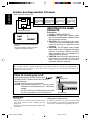
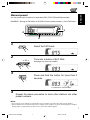
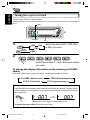
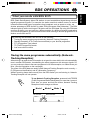
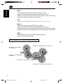
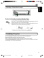
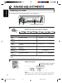
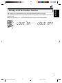
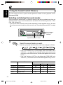
ENGLISH
DEUTSCH
CD RECEIVER
FRANÇAIS
CD-RECEIVER
RECEPTEUR CD
CD-RECEIVER
KD-S70R/S7R
NEDERLANDS
KD-S70R
KD-S7R
COMPACT
DIGITAL AUDIO
For installation and connections, refer to the separate manual.
Für den Einbau und die Anschlüsse siehe das eigenständige Handbuch.
Pour l’installation et les raccordements, se référer au manuel séparé.
Bijzonderheden over de installatie en aansluiting van het apparaat vindt u in de desbetreffende
handleiding.
INSTRUCTIONS
BEDIENUNGSANLEITUNG
MANUEL D’INSTRUCTIONS
GEBRUIKSAANWIJZING
GET0042-001A
[E]
EN00.KD-S70R/S7R[E]
3
25/3/05, 4:32 AM
Position And Reproduction Of Labels
ENGLISH
Bottom panel of the main unit
DANGER: Invisible laser
radiation when open and
interlock failedordefeated.
AVOID DIRECT EXPOSURE
TO BEAM.
(e)
ADVARSEL:Usynlig laserstråling ved åbning, når
sikkerhedsafbrydere erude
af funktion. Undgåudsættelse for stråling.
(d)
VARO: Avattaessa ja suojalukitus ohitettaessa olet
alttiina näkymättömälle
lasersäteilylle. Älä katso
säteeseen.
(f)
IMPORTANT FOR LASER
PRODUCTS
Name/Rating plate
CLASS
LASER
VARNING:Osynliglaserstrålning när denna del
är öppnadoch spärren är
urkopplad. Betrakta ej
strålen.
(s)
1
PRODUCT
Caution:
This product contains a laser component
of higher laser class than Class 1.
Precautions:
1. CLASS 1 LASER PRODUCT
2. DANGER: Invisible laser radiation when
open and interlock failed or defeated. Avoid
direct exposure to beam.
3. CAUTION: Do not open the top cover.
There are no user-serviceable parts inside.
Leave all servicing to qualified service
personnel.
4. CAUTION: This CD player uses invisible
laser radiation and is equipped with safety
switches to prevent radiation emission
when unloading CDs. It is dangerous to
defeat the safety switches.
5. CAUTION: Use of controls, adjustments or
performance of procedures other than
those specified herein may result in
hazardous radiation exposure.
Note:
For security reasons, a numbered ID card is provided with this unit, and the same ID number is
imprinted on the unit’s chassis. Keep the card in a safe place, as it will help the authorities to
identify your unit if stolen.
How to reset your unit
Press and hold both the SEL (Select) and
(Standby/On/ATT) buttons at the same time for
several seconds.
This will reset the built-in microcomputer.
NOTES: Your preset adjustments — such as preset
channels or sound adjustments — will also be
erased.
If a CD is in the unit, it will eject when you reset
the unit. Pay attention not to drop the CD.
BEFORE USE
★
For safety....
• Do not raise the volume level too much, as this
will block outside sounds, making driving
dangerous.
• Stop the car before performing any complicated
operations.
(Standby/On/ATT)
SEL (Select)
★
Temperature inside the car....
If you have parked the car for a long time in hot
or cold weather, wait until the temperature in the
car becomes normal before operating the unit.
2
EN02-04.KD-S70R/S7R[E]
2
25/3/05, 4:32 AM
ENGLISH
Thank you for purchasing a JVC product. Please read all instructions carefully before operation, to
ensure your complete understanding and to obtain the best possible performance from the unit.
CONTENTS
BASIC OPERATIONS .................................................... 4
RADIO OPERATIONS ................................................... 5
Listening to the radio ..................................................................... 5
Storing stations in memory ............................................................ 6
FM station automatic preset: SSM .............................................. 6
Manual preset .............................................................................. 7
Tuning into a preset station ........................................................... 8
RDS OPERATIONS ....................................................... 9
What you can do with RDS EON .................................................. 9
Tracing the same programme automatically
(Network-Tracking Reception) ................................................ 9
Using Standby Reception .......................................................... 11
Selecting Your Favorite Programme for
PTY Standby Reception ............................................................ 12
Searching Your Favorite Programme ........................................ 12
Other convenient RDS functions ................................................. 15
Automatic selection of the station
when using the number buttons ........................................... 15
Changing the display mode while listening to an FM station ..... 15
Setting the TA volume level ....................................................... 15
Automatic clock adjustment ..................................................... 16
CD OPERATIONS ...................................................... 17
Playing a CD ................................................................................. 17
Locating a track or a particular portion on a CD ..................... 18
Selecting CD playback modes ..................................................... 19
Prohibiting CD ejection ............................................................... 19
SOUND ADJUSTMENTS ............................................. 20
Adjusting the sound ...................................................................... 20
Turning on/off the loudness function ............................................... 21
Using the Sound Control Memory .............................................. 22
Selecting and storing the sound modes .................................... 22
Recalling the sound modes ....................................................... 23
Canceling Advanced SCM ........................................................... 24
Storing your own sound adjustments ......................................... 25
OTHER MAIN FUNCTIONS ......................................... 26
Setting the clock ............................................................................ 26
Selecting the level display ............................................................ 28
Changing the general settings ..................................................... 29
Detaching the control panel ......................................................... 32
MAINTENANCE ........................................................ 33
Handling CDs ................................................................................ 33
TROUBLESHOOTING ................................................. 34
SPECIFICATIONS ....................................................... 35
EN02-04.KD-S70R/S7R[E]
3
25/3/05, 4:32 AM
3
ENGLISH
BASIC OPERATIONS
1
2
3
1
Note:
When you use this unit for the
first time, set the built-in
clock correctly, see page 26.
Turn on the power.
/I/ATT
Note on One-Touch Operation:
When you select a source in step 2 below, the power automatically comes on.
You do not have to press this button to turn on the power.
2
CD
Select the source.
FM
To operate the tuner, see pages 5 – 16.
To operate the CD player, see pages 17 – 19.
AM
3
Adjust the volume.
Volume level appears
Volume level indicator
4
Adjust the sound as you want (see pages 20 – 25).
To drop the volume in a moment
Press
briefly while listening to any source. “ATT” starts flashing on the display, and
the volume level will drop in a moment.
To resume the previous volume level, press the button briefly again.
To turn off the power
Press
for more than 1 second.
4
EN02-04.KD-S70R/S7R[E]
4
25/3/05, 4:33 AM
RADIO OPERATIONS
ENGLISH
Listening to the radio
1
2
1
Select the band (FM1, FM2, FM3 or AM).
You can select any one of FM1, FM2 and FM3 to listen to an
FM station.
FM
AM
AM
FM1
FM2
FM3
Volume level indicator
2
selected band appears
To search stations
Start searching a station.
of higher
When a station is received, searching stops.
frequencies.
To search stations
of lower
frequencies.
To stop searching before a station is received, press the same button you have pressed
for searching.
To tune in a particular frequency without searching:
1 Press FM or AM to select the band.
2 Press and hold
¢ or 4
until “M” starts flashing on the display.
Now you can manually change the frequency while “M” is flashing.
¢ or 4
repeatedly until the frequency you want is reached.
3 Press
• If you hold down the button, the frequency keeps changing (in 50 kHz intervals for FM and
9 kHz intervals for AM – MW/LW ) until you release the button.
5
EN05-08.KD-S70R/S7R[E]
5
25/3/05, 4:34 AM
ENGLISH
Storing stations in memory
You can use one of the following two methods to store broadcasting stations in memory.
• Automatic preset of FM stations: SSM (Strong-station Sequential Memory)
• Manual preset of both FM and AM stations
FM station automatic preset: SSM
You can preset 6 local FM stations in each FM band (FM1, FM2, and FM3).
1
2
1
FM1
FM2
FM3
FM
Select the FM band number (FM1, FM2 or
FM3) you want to store FM stations into.
2
Press and hold the both buttons for more than
2 seconds.
“SSM” appears, then disappears when
automatic preset is over.
Local FM stations with the strongest signals are searched and stored automatically in the
band number you have selected (FM1, FM2 or FM3). These stations are preset in the number
buttons — No. 1 (lowest frequency) to No. 6 (highest frequency).
When automatic preset is over, the station stored in number button 1 will be automatically
tuned in.
6
EN05-08.KD-S70R/S7R[E]
6
25/3/05, 4:34 AM
ENGLISH
Manual preset
You can preset up to 6 stations in each band (FM1, FM2, FM3 and AM) manually.
EXAMPLE: Storing an FM station of 88.3 MHz into the preset number 1 of the FM1 band
1
2
3
1
Select the FM1 band.
FM
2
Tune into a station of 88.3 MHz.
See page 5 to tune into a station.
3
Press and hold the button for more than 2
seconds.
“P1” flashes for a few seconds.
4
Repeat the above procedure to store other stations into other
preset numbers.
Notes:
• A previously preset station is erased when a new station is stored in the same preset number.
• Preset stations are erased when the power supply to the memory circuit is interrupted (for example,
during battery replacement). If this occurs, preset the stations again.
7
EN05-08.KD-S70R/S7R[E]
7
25/3/05, 4:34 AM
ENGLISH
Tuning into a preset station
You can easily tune into a preset station.
Remember that you must store stations first. If you have not stored them yet, see pages 6
and 7.
DISP
1
MO/RND
1
FM1
FM2
FM3
FM
2
Select the band (FM1, FM2, FM3
or AM) you want.
AM
AM
2
Select the number (1 – 6) for the preset station
you want.
To change the display information while receiving an FM RDS
station
Press DISP. Each time you press the button, the display changes as follows:
PS NAME (Station name)
CLOCK (Clock time)
FREQ (Station frequency)
PTY (Programme type)
When an FM stereo broadcast is hard to receive:
Press MO/RND (mono/random) while listening to an FM stereo broadcast. The MO (mono)
indicator lights up on the display. The sound you hear becomes monaural but reception
will be improved.
MO/RND
Lights up when receiving an FM broadcast in stereo
To restore the stereo effect, press the button again.
8
EN05-08.KD-S70R/S7R[E]
8
25/3/05, 4:34 AM
ENGLISH
RDS OPERATIONS
What you can do with RDS EON
RDS (Radio Data System) allows FM stations to send an additional signal along with their
regular programme signals. For example, the station send their station names, as well as
information about what type of programme they broadcast, such as sports or music, etc.
Another advantage of RDS function is called “EON (Enhanced Other Networks).” The EON
indicator lights up while receiving an FM station with the EON data. By using the EON data
sent from a station, you can tune into a different station of a different network broadcasting
your favorite programme or traffic announcement while listening to another programme or to
another source such as CD.
By receiving the RDS data, this unit can do the following:
• Tracing the same programme automatically (Network-Tracking Reception)
• Standby Reception of TA (Traffic Announcement) or your favorite programme
• PTY (Programme Type) search
• TP (Traffic Programme) search
• And some other functions
Tracing the same programme automatically (NetworkTracking Reception)
When driving in an area where FM reception is not good, the tuner built in this unit automatically
tune in another RDS station, broadcasting the same programme with stronger signals. So,
you can continue to listen to the same programme in its finest reception, no matter where you
drive. (See the illustration on the next page.)
Two types of the RDS data are used to make Network-Tracking Reception work correctly —
PI (Programme Identification) and AF (Alternative Frequency).
Without receiving these data correctly from the RDS station you are listening to, NetworkTracking Reception will not operate.
TP
RDS
To use Network-Tracking Reception, press and hold TP/RDS
(Traffic Programme/Radio Data System) for more than 1 second.
Each time you press and hold the button, Network-Tracking
Reception modes change as follows:
Mode 1
Mode 2
AF indicator
Mode 3
REG indicator
AF REG
9
EN09-16.KD-S70R/S7R[E]
9
25/3/05, 4:36 AM
ENGLISH
Mode 1
The AF indicator lights up but the REG indicator does not.
Network-Tracking is activated with Regionalization set to “off.”
Switches to another station within the same network when the receiving
signals from the current station become weak.
Note:
In this mode, the programme may differ from the one currently received.
Mode 2
Both the AF indicator and the REG indicator light up.
Network-Tracking is activated with Regionalization set to “on.”
Switches to another station, within the same network, broadcasting the same
programme when the receiving signals from the current station become weak.
Mode 3
Neither the AF indicator nor the REG indicator lights up.
Network-Tracking is deactivated.
The same programme can be received on different frequencies.
Programme 1 broadcasting on frequency E
Programme 1 broadcasting
on frequency A
Programme 1 broadcasting on
frequency B
Programme 1 broadcasting on frequency C
Programme 1 broadcasting on frequency D
10
EN09-16.KD-S70R/S7R[E]
10
25/3/05, 4:36 AM
ENGLISH
Using Standby Reception
Standby Reception allows the unit to switch temporarily to your favorite programme (PTY:
Programme Type) and Traffic Announcement (TA) from the current source (another FM station
and CD).
Note:
Standby Reception will not work if you are listening to an AM station.
TA Standby Reception
TP
RDS
• When you press TP/RDS while listening to an FM station, the TP indicator
is lit during reception of a TP (Traffic Programme) station and the TA standby
mode is engaged.
Note:
When the station being received is not a TP station, the TP indicator flashes. Press
¢ or 4
to engage the TA standby mode. “SEARCH” appears on the
display, and TP station search starts. When a TP station is tuned in, the TP indicator
is lit.
• If you are listening to a CD, and wish to listen to a TP station, press TP/
RDS to enter the TA standby mode. (The TP indicator lights up.)
If a traffic programme starts broadcasting while the TA standby mode is active,
“TRAFFIC” appears and the playback source changes to the FM band. The
volume increases to the preset TA volume level and the traffic programme
can be heard (see page 15).
To deactivate the TA standby mode, press TP/RDS again.
PTY Standby Reception
PTY
• When you press PTY while listening to an FM station, the PTY indicator is
lit during reception of a PTY station and the PTY standby mode is engaged.
The selected PTY name stored on page 13 flashes for 5 seconds.
Note:
When the station being received is not a PTY station, the PTY indicator flashes.
Press
¢ or 4
to engage the PTY standby mode. “SEARCH” appears on
the display, and PTY station search starts. When a PTY station is tuned in, the PTY
indicator is lit.
• If you are listening to a CD, and wish to listen to a selected PTY broadcast,
press PTY to enter the PTY standby mode. (The PTY indicator lights up.)
If the selected PTY programme starts broadcasting while the PTY standby
mode is active, the selected PTY name appears and the playback source
changes to the FM band. The selected PTY programme can then be heard.
To deactivate the PTY standby mode, press PTY again.
11
EN09-16.KD-S70R/S7R[E]
11
25/3/05, 4:37 AM
ENGLISH
Selecting Your Favorite Programme for PTY Standby
Reception
You can select your favorite programme for PTY Standby Reception to store in memory.
When shipped from the factory, “NEWS” is stored as the programme type for PTY Standby
Reception.
1, 4
3
2
1
Press and hold SEL for more than 2 seconds
to enter the general setting mode (see page
29).
SEL
2
Select “PTY STBY (standby)” if not shown on
the display.
3
Select one of twenty-nine PTY codes. (See
page 16.)
Selected code name appears on the display and is stored
into memory.
4
SEL
Finish the setting.
Searching Your Favorite Programme
You can search one of your 6 favorite programme types stored in memory.
When shipped from the factory, the following 6 programme types have been stored in the
number buttons (1 to 6).
To change the factory preset settings, see page 13.
To search your favorite programme, see page 14.
1
2
3
4
5
6
POP M
ROCK M
EASY M
CLASSICS
AFFAIRS
VARIED
12
EN09-16.KD-S70R/S7R[E]
12
25/3/05, 4:37 AM
ENGLISH
To store your favorite programme types
1, 5
3
2
1
4
Press and hold SEL for more than 2 seconds
to call up the general setting mode (see page
29).
SEL
2
Select “PTY SRCH (search)” if not shown on
the display.
3
Select one of twenty-nine PTY codes.
(See page 16.)
Selected code name appears on the display.
• If the code already stored in memory is selected, it will
flash on the display.
4
Press and hold the number button for more than 2 seconds to
store the PTY code selected into the preset number you want.
The selected code name will flash on the display.
5
SEL
Finish the setting.
13
EN09-16.KD-S70R/S7R[E]
13
25/3/05, 4:37 AM
ENGLISH
To search your favorite programme type
2
1
1
Press and hold PTY for more than 1 second
while listening to an FM station.
PTY
The last selected PTY code appears.
2
Select one of PTY codes stored in preset
number buttons (1 to 6).
Ex. When “ROCK M” is stored in preset number button 2.
PTY search for your favorite programme starts after 5
seconds.
• If there is a station broadcasting a programme of the same PTY code you have selected,
that station is tuned in.
• If there is no station broadcasting a programme of the same PTY code you have selected,
the station will not change.
Note:
In some areas, the PTY search will not work correctly.
14
EN09-16.KD-S70R/S7R[E]
14
25/3/05, 4:37 AM
ENGLISH
Other convenient RDS functions and adjustments
Automatic selection of the station when using the number
buttons
Usually when you press the number button, the preset station is tuned in.
However, when the preset station is an RDS station, something different will happen. If the
signals from that preset station are not sufficient for good reception, this unit, using the AF
data, tunes in another frequency broadcasting the same programme as the original preset
station is broadcasting. In case no other station is tuned in, you can also search all receivable
frequencies for the same programme. (Programme search) To activate programme search,
follow the procedure below.
• Programme search takes a while.
• See also “Changing the general settings” on page 29.
1. Press and hold SEL (select) for more than 2 seconds to call up the general setting mode.
¢ or 4
to select “P(programme)-SEARCH.”
2. Press
3. Press the + button and set to "ON".
Now programme search is activated.
To cancel programme search, repeat the same procedure and select “OFF” in step 3 by
turning the control dial counterclockwise.
Changing the display mode while listening to an FM
station
You can change the initial indication on the display to station name (PS NAME), station
frequency (FREQ), or clock time (CLOCK) while listening to an FM RDS station.
• See also “Changing the general settings” on page 29.
1. Press and hold SEL (select) for more than 2 seconds to call up the general setting mode.
¢ or 4
to select “DISPMODE (display mode).”
2. Press
3. Press + or – to set to the desired indication — PS NAME (station name), FREQ (station
frequency), or CLOCK (clock time).
Note:
By pressing DISP, you can also change the display while listening to an FM RDS station.
Each time you press the button, the following information appears on the display:
PS NAME (Station name)
CLOCK (Clock time)
FREQ (Station frequency)
PTY (Programme type)
* Then, the display goes back to the original indication in several seconds.
Setting the TA volume level
You can preset the volume level for TA Standby Reception. When a traffic programme is
received, the volume level automatically changes to the preset level.
• See also “Changing the general settings” on page 29.
1. Press and hold SEL (select) for more than 2 seconds to call up the general setting mode.
¢ or 4
to select “TA VOL (volume).”
2. Press
3. Press + or – to the desired volume.
EN09-16.KD-S70R/S7R[E]
15
25/3/05, 4:37 AM
15
ENGLISH
Automatic clock adjustment
When shipped from the factory, the clock built in this unit is set to be readjust automatically
using the CT (Clock Time) data in the RDS signal.
If you do not want to use automatic clock adjustment, follow the procedure below.
• See also “Changing the general settings” on page 29.
1. Press and hold SEL (select) for more than 2 seconds to call up the general setting mode.
¢ or 4
to select “AUTO ADJ (adjust).”
2. Press
3. Press – to select “ADJ OFF.”
Now automatic clock adjustment is canceled.
To reactivate clock adjustment, repeat the same procedure and select “ADJ ON” in step 3
by pressing the + button.
Note:
It takes about 2 minutes to adjust the time using the CT data. So, you must tune to the station for more
than 2 minutes continuously; otherwise, the clock time will not be adjusted.
PTY codes
NEWS:
AFFAIRS:
News
Topical programmes
expanding on current news
or affairs
INFO:
Programmes which impart
advice on a wide variety of
topics
SPORT:
Sport events
EDUCATE: Educational programmes
DRAMA:
Radio plays
CULTURE: Programmes on national or
regional culture
SCIENCE:
Programmes on natural
science and technology
VARIED:
Other programmes like
comedies or ceremonies
POP M:
Pop music
ROCK M:
Rock music
EASY M:
Easy-listening music
LIGHT M:
Light music
CLASSICS: Classical music
OTHER M: Other music
WEATHER: Weather information
FINANCE:
Reports on commerce,
trading, the Stock Market,
etc.
CHILDREN: Entertainment programmes
for children
SOCIAL:
Programmes on social
activities
RELIGION: Programmes dealing with
any aspect of belief or faith,
or the nature of existence or
ethics
PHONE IN: Programmes where people
can express their views
either by phone or in a
public forum
TRAVEL:
Programmes about travel
destinations, package tours,
and travel ideas and
opportunities
LEISURE:
Programmes concerned with
recreational activities such
as gardening, cooking,
fishing, etc.
JAZZ:
Jazz music
COUNTRY: Country music
NATION M: Current popular music from
another nation or region, in
that country’s language
OLDIES:
Classic pop music
FOLK M:
Folk music
DOCUMENT: Programmes dealing with
factual matters, presented in
an investigative style
16
EN09-16.KD-S70R/S7R[E]
16
25/3/05, 4:37 AM
CD OPERATIONS
ENGLISH
Playing a CD
0
1
1
Insert a disc into the loading slot.
The unit turns on, draws a CD and starts playback
automatically.
• When a CD is inserted upside down, the CD ejects
automatically.
A
A
Total playing time of
the inserted disc
Total track number
of the inserted disc
Elapsed playing
time
Current track
Note on One-Touch Operation:
When a CD is already in the loading slot, pressing CD turns on the unit and starts playback
automatically.
CAUTION on Volume Setting
CDs produces very little noise compared with other sources. If the volume level is adjusted
for the tuner, for example, the speakers may be damaged by the sudden increase in the
output level. Therefore, lower the volume before playing a CD and adjust it as required
during playback.
To stop play and eject the CD
Press 0.
CD play stops and the CD automatically ejects from the loading slot. The source changes to
the tuner (you will hear the last received station).
If you change the source to AM or FM, the CD play also stops (without ejecting the CD this
time).
• If the ejected disc is not removed for about 15 seconds, the disc is automatically inserted again into
the loading slot to protect it from dust. (CD play will not start this time.)
• You can eject the CD even when the unit is turned off.
17
EN17-19.KD-S70R/S7R[E]
17
25/3/05, 4:39 AM
ENGLISH
Locating a track or a particular portion on a CD
¢
4
Number buttons
To fast forward or reverse the track
¢, while playing a CD, to fast forward the track.
Press and hold
Press and hold 4
, while playing a CD, to reverse the track.
To go to the next track or the previous track
Press
¢ briefly, while playing a CD, to go ahead to the beginning of
the next track. Each time you press the button consecutively, the beginning
of the next tracks is located and played back.
briefly, while playing a CD, to go back to the beginning of the
Press 4
current track. Each time you press the button consecutively, the beginning
of the previous tracks is located and played back.
To go to a particular track directly
7
8
9
10
11
12
Press the number button corresponding to the track number to start its
playback.
• To select a track number from 1 – 6:
Press 1 (7) – 6 (12) briefly.
• To select a track number from 7 – 12:
Press and hold 1 (7) – 6 (12) for more than 1 second.
18
EN17-19.KD-S70R/S7R[E]
18
25/3/05, 4:39 AM
ENGLISH
Selecting CD playback modes
MO/RND
To play back tracks at random (Random Play)
You can play back all tracks on the CD at random.
MO/RND
Each time you press MO/RND (Mono/Random) while playing a CD, CD
random play mode turns on and off alternatively.
When the random mode is turned on, the RND indicator lights up on the
display and a track randomly selected starts playing.
• To select the next track at random, press
¢ briefly.
Prohibiting CD ejection
You can prohibit the CD ejection and can “lock” a CD in the loading slot.
Press and hold CD and 0 for more than 2 seconds.
“EJECT” flashes on the display for about 5 seconds, and the CD is “locked.”
To cancel the prohibition and “unlock” the CD, press and hold CD and 0 for more than 2
seconds again. The CD ejects automatically.
19
EN17-19.KD-S70R/S7R[E]
19
25/3/05, 4:39 AM
ENGLISH
SOUND ADJUSTMENTS
Adjusting the sound
You can adjust the sound characteristics to your preference.
2
1
1
Equalization pattern indicator
Select the item you want to adjust.
Indication
To do:
Range
BAS
(Bass)
Adjust the bass
–6 (min.)
—
+6 (max.)
TRE
(Treble)
Adjust the treble
–6 (min.)
—
+6 (max.)
FAD
(Fader)*
Adjust the front and rear speaker
balance
BAL
(Balance)
Adjust the left and right speaker
balance
LOUD
(Loudness)
See page 21
VOL
(Volume)
Adjust the volume
R6 (rear only) — F6 (front only)
L6 (left only)
— R6 (right only)
See page 21
00 (min.)
—
50 (max.)
Note:
* If you are using a two-speaker system, set the fader level to “00.”
2
Adjust the level.
Equalization pattern changes as
you adjust the bass or treble
Note:
Normally the + and – buttons work as the volume control buttons.
So you do not have to select “VOL” to adjust the volume level.
20
EN20-25.KD-S70R/S7R[E]
20
25/3/05, 4:39 AM
ENGLISH
Turning on/off the loudness function
The human ear is less sensitive to low and high frequencies at low volumes.
The loudness function can boost these frequencies to produce well-balanced sound at low
volume level.
Each time you press + or –, the loudness function turns on and off alternatively.
@A
21
EN20-25.KD-S70R/S7R[E]
21
25/3/05, 4:39 AM
ENGLISH
Using the Sound Control Memory
You can select and store a preset sound adjustment suitable to each playback source.
(Advanced SCM)
Selecting and storing the sound modes
Once you select a sound mode, it is stored in memory, and will be recalled every time you
select the same source. A sound mode can be stored each of the following sources — FM1,
FM2, FM3, AM and CD.
• If you do not want to store the sound mode separately for each playback source, but want
to use the same sound mode for all the sources, see “Canceling Advanced SCM” on page
24.
”Link“ indicator/
sound mode
indicators
1
Equalization pattern indicator
1
SCM
Select the sound mode you want.
Each time you press the button, the sound mode changes as follows.
• If the “Link” indicator is lit on the display (with “SCM LINK” set to
“LINK ON” — see page 24), the selected sound mode can be stored
in memory for the current source, and the effect applies to the current
source.
• If the “Link” indicator is NOT lit on the display (with “SCM LINK” set to
“LINK OFF”), the selected sound mode effect applies to any source.
Indication
For:
Preset values
Bass
Treble
Loudness
00
00
On
Rock or disco music
+02
00
On
SOFT
Quiet background music
+01
–03
Off
POP
Light music
+04
+01
Off
SCM OFF
(Flat sound)
BEAT
22
EN20-25.KD-S70R/S7R[E]
22
25/3/05, 4:39 AM
ENGLISH
Recalling the sound modes
1
1
Select the source while the “Link” indicator
is lit on the display.
CD
FM
The “Link” indicator starts flashing, and the sound mode
stored in memory for the selected source is recalled.
AM
Equalization pattern of the
selected sound mode appears
Sound mode
indicator
Notes:
• You can adjust each sound mode to your preference, and store it in memory.
If you want to adjust and store your original sound mode, see “Storing your own sound adjustments”
on page 25.
• To adjust the bass and treble reinforcement levels or to turn on/off the loudness function temporarily,
see pages 20 and 21. (Your adjustments will be cancelled if another source is selected.)
23
EN20-25.KD-S70R/S7R[E]
23
25/3/05, 4:39 AM
ENGLISH
Canceling Advanced SCM
You can cancel the Advanced SCM (Sound Control Memory), and unlink the sound modes
and the playback sources.
When shipped from the factory, a different sound mode can be stored in memory for each
source so that you can change the sound modes simply by changing the sources.
LINK ON: Advanced SCM (different SCMs for different sources)
LINK OFF: Conventional SCM (one SCM for all sources)
3
1,4 2
1
Press and hold SEL for more than 2 seconds
to call up the general setting mode (see page
29).
2
Select “SCM LINK” if not shown on the display.
3
Select the desired mode — “LINK ON” or
“LINK OFF”.
4
Finish the setting.
24
EN20-25.KD-S70R/S7R[E]
24
25/3/05, 4:39 AM
ENGLISH
Storing your own sound adjustments
You can adjust the sound modes (BEAT, SOFT, POP: see page 22) to your preference and
store your own adjustments in memory.
2
3
1, 4
1
SCM
Call up the sound mode you want to adjust.
See page 22 for details.
2
Within
5 seconds
SEL
Select “BAS”, “TRE” or “LOUD.”
3
Within
5 seconds
Adjust the bass or treble level or turn the
loudness function ON/OFF.
See page 20 for details.
Within
5 seconds
4
Press and hold SCM until the sound mode
you have selected in step 1 flashes on the
display.
SCM
Your setting is stored in memory.
5
Repeat the same procedure to store other settings.
To reset to the factory settings
Repeat the same procedure and reassign the preset values listed in the table on page 22.
25
EN20-25.KD-S70R/S7R[E]
25
25/3/05, 4:39 AM
ENGLISH
OTHER MAIN FUNCTIONS
Setting the clock
You can also set the clock system either to 24 hours or 12 hours.
1, 5
2, 3, 4
2, 3, 4
1
2
SEL
Press and hold SEL for more than 2 seconds to call
up the general setting mode (see page 29).
1
2
Set the hour.
1 Select “CLOCK H (Hour)” if
not shown on the display.
2 Adjust the hour.
3
1
2
Set the minute.
1 Select “CLOCK M (Minute).”
2 Adjust the minute.
26
EN26-32.KD-S70R/S7R[E]
26
25/3/05, 4:40 AM
1
2
Set the clock system.
1
2
5
ENGLISH
4
Select “24H/12H.”
Select “24H” or “12H.”
Finish the setting.
SEL
To check the current clock time (changing the display mode)
Press DISP repeatedly. Each time you press the button, the display mode changes as follows.
During tuner operation:
Clock
During CD operation:
Frequency
Clock
Elapsed playing time
Note:
For the indication change during RDS operation,
see page 15.
• If the unit is not in use when you press DISP, the power turns on, the clock time is shown for
5 seconds, then the power turns off.
27
EN26-32.KD-S70R/S7R[E]
27
25/3/05, 4:40 AM
ENGLISH
Selecting the level display
You can select the level display according to your preference.
When shipped from the factory, “VOL 2” is selected.
VOL 1: Shows the volume level indicator and the equalization pattern indicator.
VOL 2: Alternates “VOL 1” setting and illumination display.
OFF: Erase the volume level indicator and the equalization pattern indicator.
Equalization pattern indicator
3 1,4 2
Volume level indicator
1
Press and hold SEL for more than 2 seconds
to call up the general setting mode (see page
29).
2
Select “LEVEL” if not shown on the display.
3
Select the desired mode — “VOL 1”, “VOL 2”
or “OFF”.
4
Finish the setting.
28
EN26-32.KD-S70R/S7R[E]
28
25/3/05, 4:40 AM
ENGLISH
Changing the general settings
You can change the items listed on the next page to your preference.
Basic Procedure
1, 4
3
2
1
Press and hold SEL for more than 2 seconds to
call up the general setting mode.
SEL
2
Select the item you want to adjust.
(See page 30.)
3
4
Adjust the item selected above.
Finish the setting.
SEL
29
EN26-32.KD-S70R/S7R[E]
29
25/3/05, 4:40 AM
ENGLISH
4
3
2
1
SEL
SEL
Finish the setting
Select.
Set.
CLOCK H
Hour adjustment
Back
Advance
CLOCK M
Minute adjustment
Back
Advance
SCM LINK
Sound control
memory linkage
LINK ON
24H/12H
24/12-hour time
display
AUTO ADJ
Automatic setting of
the clock
DISPMODE
Display mode
Factorypreset
settings
See
page
0:00
26
LINK OFF
LINK ON
24
12H
24H
24H
27
OFF
ON
ON
16
PS NAME
15
29 programme types
(See page 16.)
NEWS
(See page 12.)
12
VOL (00-50)
VOL (20)
15
OFF
15
OFF
31
VOL 2
28
PS NAME
FREG
CLOCK
PTY STBY
PTY standby
PTY SRCH
PTY search
TA VOL
Traffic announcement
volume
P-SEARCH
Programme search
TEL
Audio mute for
cellular phone system
OFF
LEVEL
Level display
OFF
ON
OFF
MUTING 1
MUTING 2
VOL 1
VOL 2
30
EN26-32.KD-S70R/S7R[E]
30
25/3/05, 4:40 AM
12
ENGLISH
Selecting the telephone muting
This mode is used when a cellular phone system is connected. Depending on the phone
system used, select either “MUTING 1” or “MUTING 2,” whichever mutes the sounds from
this unit. When shipped from the factory, this mode is deactivated.
• MUTING 1: Select this if this setting can mute the sounds.
• MUTING 2: Select this if this setting can mute the sounds.
• OFF:
Cancels the telephone muting.
1. Press and hold SEL (select) for more than 2 seconds to call up the general setting mode.
¢ or 4
to select “TEL (telephone)”.
2. Press
3. Press + or – to select the desired mode.
The telephone muting mode changes as follows:
MUTING 1
MUTING 2
OFF
31
EN26-32.KD-S70R/S7R[E]
31
25/3/05, 4:40 AM
ENGLISH
Detaching the control panel
You can detach the control panel when leaving the car.
When detaching or attaching the control panel, be careful not to damage the connectors on
the back of the control panel and on the panel holder.
How to detach the control
panel
Before detaching the control panel, be sure
to turn off the power.
1
2
3
How to attach the control
panel
1
Unlock the control panel.
Lift and pull the control panel
out of the unit.
Put the detached control
panel into the case provided.
2
Insert the left side of the
control panel into the groove
on the panel holder.
Press the right side of the
control panel to fix it to the
panel holder.
Note on cleaning the connectors:
If you frequently detach the control panel, the
connectors will deteriorate.
To minimize this possibility, periodically wipe
the connectors with a cotton swab or cloth
moistened with alcohol, being careful not to
damage the connectors.
Connectors
32
EN26-32.KD-S70R/S7R[E]
32
25/3/05, 4:40 AM
MAINTENANCE
ENGLISH
Handling CDs
COMPACT
This unit has been designed only to reproduce the CDs bearing the
Other discs cannot be played back.
mark.
DIGITAL AUDIO
How to handle CDs
When removing a CD from its case, press down the center holder of the case
and lift the CD out, holding it by the edges.
• Always hold the CD by the edges. Do not touch its recording surface.
When storing a CD into its case, gently insert the CD around the center
holder (with the printed surface facing up).
• Make sure to store CDs into the cases after use.
Center holder
To keep CDs clean
A dirty CD may not play correctly. If a CD does becomes dirty, wipe it with a soft
cloth in a straight line from center to edge.
To play new CDs
New CDs may have some rough spots around the inner and outer edges. If such
a CD is used, this unit may reject the CD.
To remove these rough spots, rub the edges with a pencil or ball-point pen, etc.
Moisture condensation
Moisture may condense on the lens inside the CD player in the following cases:
• After starting the heater in the car.
• If it becomes very humid inside the car.
Should this occur, the CD player may malfunction. In this case, eject the CD and leave the unit turned on
for a few hours until the moisture evaporates.
CAUTIONS:
• Do not insert 8cm (3 3/16") CDs (single CDs) into the loading slot. (Such CDs cannot be ejected.)
• Do not insert any CD of unusual shape – like a heart or flower; otherwise, it will cause a malfunction.
• Do not expose CDs to direct sunlight or any heat source or place them in a place subject to high temperature
and humidity. Do not leave them in a car.
• Do not use any solvent (for example, conventional record cleaner, spray, thinner, benzine, etc.) to clean
CDs.
When playing a CD-R (Recordable)
You can play back your original CD-Rs on this recevier.
• Before playing back CD-Rs, read their instructions or cautions carefully.
• Some CD-Rs recorded on CD recorders may not be played back on this receiver because of their disc
characteristics, and of the following reasons:
– Discs are dirty or scratched.
– Moisture condensation occurs on the lens inside the unit.
– The pickup lens inside the CD player is dirty.
• Use only “finalized” CD-Rs.
• CD-RWs (Rewritable) cannot be played back on this recevier.
About mistracking:
Mistracking may result from driving on extremely rough roads. This does not damage the unit and
the CD, but will be annoying.
We recommend that you stop CD play while driving on such rough roads.
33
EN33-35.KD-S70R/S7R[E]
33
25/3/05, 4:41 AM
ENGLISH
TROUBLESHOOTING
What appears to be trouble is not always serious. Check the following points before calling a
service center.
Symptoms
Causes
Remedies
• CD cannot be played back.
CD is inserted upside down.
Insert the CD correctly.
• CD sound is sometimes
interrupted.
You are driving on rough
roads.
Stop CD play while driving on
rough roads.
CD is scratched.
Change the CD.
Connections are incorrect.
Check the cords and
connections.
No CD is in the loading slot.
Insert a CD into the loading
slot.
CD is inserted incorrectly.
Insert it correctly.
The volume control is turned
to the minimum level.
Adjust it to the optimum level.
Connections are incorrect.
Check the cords and
connections.
• SSM (Strong-station
Sequential Memory)
automatic preset does not
work.
Signals are too weak.
Store stations manually.
• Static noise while listening
to the radio.
The antenna is not connected
firmly.
Connect the antenna firmly.
• CD can be neither played
back nor ejected.
The CD player may function
incorrectly.
and 0 at the
Press
same time for more than 2
seconds. Be careful not to
drop CD when it is ejected.
• The unit does not work at
all.
Press
and SEL at
The built-in microcomputer
may function incorrectly due to the same time for more than 2
seconds to reset the unit. (The
noise, etc.
clock setting and preset
stations stored in memory are
erased.) (See page 2.)
• “NO DISC” appears on the
display.
• Sound cannot be heard from
the speakers.
34
EN33-35.KD-S70R/S7R[E]
34
25/3/05, 4:41 AM
AUDIO AMPLIFIER SECTION
CD PLAYER SECTION
Maximum Power Output:
Front: 40 W per channel
Rear: 40 W per channel
Continuous Power Output (RMS):
Front: 16 W per channel into 4 Ω, 40 Hz
to 20 000 Hz at no more than 0.8%
total harmonic distortion.
Rear: 16 W per channel into 4 Ω, 40 Hz
to 20 000 Hz at no more than 0.8%
total harmonic distortion.
Load Impedance: 4 Ω (4 Ω to 8 Ω allowance)
Tone Control Range
Bass: ±10 dB at 100 Hz
Treble:±10 dB at 10 kHz
Frequency Response: 40 Hz to 20 000 Hz
Signal-to-Noise Ratio: 70 dB
Line-Out Level/Impedance: 2.0 V/20 kΩ load
(full scale)
Output Impedance: 1kΩ
Type: Compact disc player
Signal Detection System: Non-contact optical
pickup (semiconductor laser)
Number of channels: 2 channels (stereo)
Frequency Response: 5 Hz to 20 000 Hz
Dynamic Range: 96 dB
Signal-to-Noise Ratio: 98 dB
Wow and Flutter: Less than measurable limit
TUNER SECTION
Frequency Range
FM: 87.5 MHz to 108.0 MHz
AM: (MW) 522 kHz to 1 620 kHz
(LW) 144 kHz to 279 kHz
ENGLISH
SPECIFICATIONS
GENERAL
Power Requirement
Operating Voltage: DC 14.4 volts (11 V to
16 V allowance)
Allowable Working Temperature:
0°C to +40°C
Grounding System: Negative ground
Dimensions (W x H x D)
Installation Size:
182 mm x 52 mm x 150 mm
Panel Size: 188 mm x 58 mm x 14 mm
Mass: 1.3 kg (excluding accessories)
Design and specifications subject to change
without notice.
[FM Tuner]
Usable Sensitivity: 11.3 dBf (1.0 µV/75 Ω)
50 dB Quieting Sensitivity:
16.3 dBf (1.8 µV/75 Ω)
Alternate Channel Selectivity (400 kHz):
65 dB
Frequency Response: 40 Hz to 15 000 Hz
Stereo Separation: 30 dB
Capture Ratio: 1.5 dB
[MW Tuner]
Sensitivity: 20 µV
Selectivity: 35 dB
[LW Tuner]
Sensitivity: 50 µV
35
EN33-35.KD-S70R/S7R[E]
35
25/3/05, 4:41 AM
Having TROUBLE with operation?
Please reset your unit
Refer to page of How to reset your unit
Haben Sie PROBLEME mit dem Betrieb?
Bitte setzen Sie Ihr Gerät zurück
Siehe Seite Zurücksetzen des Geräts
Vous avez des PROBLÉMES de fonctionnement?
Réinitialisez votre appareil
Référez-vous à la page intitulée Comment réinitialiser votre appareil
Hebt u PROBLEMEN met de bediening?
Stel het apparaat terug
Zie de pagina met de paragraaf Het apparaat terugstellen
VICTOR COMPANY OF JAPAN, LIMITED
V
EN, GE, FR, NL
EN00.KD-S70R/S7R[E]
J
2
C
1200HISFLEJES
25/3/05, 4:32 AM
KD-S70R
KD-S7R
Installation/Connection Manual
Einbau/Anschlußanleitung
Manuel d’installation/raccordement
GET0042-003A
[E]
V
J
ENGLISH
DEUTSCH
C
1200HISFLEJES
EN, GE, FR
FRANÇAIS
• This unit is designed to operate only on 12 volts DC, NEGATIVE
ground electrical systems.
• Dieses Gerät ist nur für einen Betrieb in elektrischen Anlagen
mit 12 V Gleichstrom und (–) Erdung ausgelegt.
• Cet appareil est conçu pour fonctionner sur des sources de
courant continu de 12 volts à masse NEGATIVE seulement.
INSTALLATION
(IN-DASH MOUNTING)
EINBAU
(IM ARMATURENBRETT)
INSTALLATION
(MONTAGE DANS LE TABLEAU DE BORD)
• The following illustration shows a typical installation. However,
you should make adjustments corresponding to your specific
car. If you have any questions or require information regarding
installation kits, consult your JVC IN-CAR ENTERTAINMENT
dealer or a company supplying kits.
• Die folgende Abbildung zeigt einen typischen Einbau. Dennoch
müssen Sie entsprechend Ihrem jeweiligen Auto Anpassungen
vornehmen. Bei irgendwelchen Fragen oder wenn Sie
Informationen hinsichtlich des Einbausatzes brauchen, wenden
Sie sich an ihren JVC Autoradiohändler oder ein Unternehmen
das diese Einbausätze vertreibt.
• L’illustration suivante est un exemple d’installation typique.
Cependant, vous devez faire les ajustements correspondant à
votre voiture particulière. Si vous avez des questions ou avez
besoin d’information sur des kits d’installation, consulter votre
revendeur d’autoradios JVC ou une compagnie
d’approvisionnement.
1
Before mounting: Press
(Control Panel Release) to
detach the control panel if already attached.
1
* When shipped from the factory, the control panel is packed
in the hard case.
2
3
Remove the trim plate.
Remove the sleeve after disengaging the sleeve locks.
1 Stand the unit.
2
3
Fix the mounting bolt to the rear of the unit’s body and place
the rubber cushion over the end of the bolt.
6
7
8
Do the required electrical connections.
9
Attach the control panel.
Die Halterung nach dem Entriegeln der Halterungensperren
abnehmen.
* Lorsque ce panneau de commande sort d’usine, il est
rangé dans un étui de transport.
2
3
Retirer la plaque d’assemblage.
Libérer les verrous du manchon et retirer le manchon.
1 Poser l’appareil à la verticale.
Remarque: Lorsque vous mettez l’appareil à la verticale,
faire attention de ne pas endommager le fusible situé
sur le fond.
2 Insérer les 2 poignées entre l’appareil et le manchon
comme indiqué pour désengagé les verrous de manchon.
3 Retirer le manchon.
Remarque: S'assurer de garder les poignées pour une
utilisation ultérieur, après l'installation de l'appareil.
4
Installer le manchon dans le tableau de bord.
4
Die Halterung im Armaturenbrett einbauen.
* Nach dem korrekten Einbau der Halterung im Armaturenbrett,
die entsprechenden Riegel umknicken, um die Halterung
an ihrem Platz zu sichern, siehe Abbildung.
5
Die Befestigungsschraube an der Rückseite des
Gerätekörpers befestigen und das Ende der Schraube mit
einem Gummipuffer abdecken.
6
7
8
Nehmen Sie die erforderlichen elektrischen Anschlüsse vor.
Befestigen Sie die Frontrahmen in der Form, daß der Fortsatz
der Frontrahmen auf der linken Seite des Geräts befestigt wird.
8
Attachez la plaque d’assemblage de façon que la projection
de la plaque soit fixée sur le côté gauche de l’appareil.
9
Die Schalttafel anbringen.
9
Remonter le panneau de commande.
Slide the unit into the sleeve until it is locked.
Attach the trim plate so that the projection on the trim plate
is fixed to the left side of the unit.
Den Frontrahmen herausnehmen.
Hinweis: Sicherstellen, daß die Griffe für künftigen
Gebrauch nach dem Einbau des Geräts aufbewahrt
werden.
Install the sleeve into the dashboard.
5
Avant le montage: Appuyez sur
(déblocage du
panneau de commande) pour éventuellement détacher le
panneau de commande.
1 Das Gerät aufstellen.
Hinweis: Beim Aufstellen des Geräts darauf achten, daß
die Sicherung auf der Rückseite nicht beschädigt wird.
2 Die beiden Griffe zwischen dem Gerät und der Halterung
wie abgebildet einstecken und die Halterungensperren
entriegeln.
3 Die Halterung entfernen.
Note: Be sure to keep the handles for future use after
installing the unit.
* After the sleeve is correctly installed in the dashboard,
bend the appropriate tabs to hold the sleeve firmly in place,
as illustrated.
1
* Bei der Auslieferung ab Werk ist die Bedienungsblende
im Etui verpackt.
Note: When you stand the unit, be careful not to damage
the fuse on the rear.
2 Insert the 2 handles between the unit and the sleeve, as
illustrated, to disengage the sleeve locks.
3 Remove the sleeve.
4
Vor dem Einbau: Drücken Sie
(Freigabe der
Bedienungsblende), um die Arretierung der Bedienungsblende
zu lösen, sofern diese bereits angerbracht ist.
Das Gerät in die Halterung schieben, bis es einrastet.
* Après installation correcte du manchon dans le tableau
de bord, plier les bonnes pattes pour maintenir fermement
le manchon en place, comme montré.
5
Monter le boulon de montage sur l’arrière du corps de
l’appareil puis passer l’amortisseur en caoutchouc sur
l’extrémité du boulon.
6
7
Réalisez les connexions électriques.
Faire glisser l’appareil dans le manchon jusqu’à ce qu’il soit
verrouillé.
2
1
Dashboard
Armaturenbrett
Tableau de bord
Rubber cushion
Gummipuffer
Amortisseur en caoutchouc
Sleeve
Halterung
Manchon
3
8
Fuse
Sicherung
Fusible
Lock plate
Arretierplättchen
Plaque de verrouillage
Trim plate
Frontrahmen
Plaque d’assemblage
Sleeve
Halterung
Manchon
EN.GE.FR.KD-S70R/S7R[E]
1
28/12/00, 6:13 PM
m
53
5
mm
Mounting bolt
Befestigungsschraube
Boulon de montage
4*
9
Slot
Schlitz
Fente
4m
4
7
Handles
Griffe
Poignées
18
6
See the back page for electrical
connections.
Siehe Rückseite für elektrische
Anschlüsse.
Voir le dos de cette page pour les
connexions électriques.
• When using the optional stay
• Beim Verwenden der Anker-Option
• Lors de l'utilisation du hauban en option
• When installing the unit without using the sleeve
• Beim Einbau des Geräts ohne Halterung
• Lors de l'installation de l’appareil sans utiliser de manchon
In a Toyota for example, first remove the car radio and install the unit in its place.
Zum Beispiel in einem Toyota zuerst das Autoradio ausbauen und dann das Gerät an seinem Platz einbauen.
Par exemple dans une Toyota, retirer d’abord l’autoradio et installer l’appareil à la place.
Fire wall
Feuerwand
Cloison
Dashboard
Armaturenbrett
Tableau de bord
Stay (option)
Anker (Option)
Hauban (en option)
Washer
Unterlegscheibe
Rondelle
Flat type screws (M5 x 6 mm)*
Senkkopfschrauben (M5 x 6 mm)*
Vis à tête plate (M5 x 6 mm)*
Lock nut
Sicherungsmutter
Ecrou d’arrêt
Bracket*
Konsole*
Support*
Screw (option)
Schraube (Option)
Vis (en option)
Pocket
Taschen
Poche
Mounting bolt
Befestigungsschraube
Boulon de montage
Sleeve
Halterung
Manchon
* Not included with this unit.
* Nicht Teil dieses Geräts.
* Non fourni avec cet appareil.
Bracket*
Konsole*
Support*
Flat type screws (M5 x 6 mm)*
Senkkopfschrauben (M5 x 6 mm)*
Vis à tête plate (M5 x 6 mm)*
Note: When installing the unit on the mounting bracket, make sure to use the 6 mm-long screws. If
longer screws are used, they could damage the unit.
Hinweis: Beim Anbringen des Gerät an der Konsole sicherstellen, daß 6 mm lange Schrauben
verwendet werden. Werden längere Schrauben verwendet, können sie das Gerät beschädigen.
Remarque: Lors de l'installation de l’appareil sur le support de montage, s’assurer d’utiliser des vis
d’une longueur de 6 mm. Si des vis plus longues sont utilisées, elles peuvent endommager l’appareil.
Removing the unit
Ausbau des Geräts
Retrait de l’appareil
• Before removing the unit, release the rear section.
• Vor dem Ausbau des Geräts den hinteren Teil freigeben.
• Avant de retirer l’appareil, libérer la section arrière.
1
Remove the control panel.
1
Die Schalttafel abnehmen.
1
Retirer le panneau de commande.
2
Remove the trim plate.
2
Den Frontrahmen abnehmen.
2
Retirer la plaque d’assemblage.
3
Insert the 2 handles into the slots, as shown. Then,while gently
pulling the handles away from each othe, slide out the unit.
(Be sure to keep the handles after installing it.)
3
Die 2 Griffe in die Schlitze wie gezeigt stecken. Dann die Griffe
behutsam auseinander ziehen und das Gerät herausziehen.
(Die Griffe nach dem Einbau auf jeden Fall aufbewahren.)
3
Introduire les deux poignées dans les fentes, comme montré.
Puis, tout en tirant doucement les poignées écartées, faire
glisser l’appareil pour le sortir. (S'assurer de conserver les
poignées après l’installation de l’appareil.)
1
2
3
Handle
Griff
Poignée
Parts list for installation and connection
Teileliste für den Einbau und Anschluß
Liste des pièces pour l’installation et raccordement
The following parts are provided with this unit.
After checking them, please set them correctly.
Die folgenden Teile werden zusammen mit diesem Gerät geliefert.
Nach ihrer Überprüfung, die Teile richtig einsetzen.
Les pièces suivantes sont fournies avec cet appareil.
Après vérification, veuillez les placer correctement.
Hard case/Control Panel
Etui/Schalttafel
Etui de transport/
Panneau de command
Trim plate
Frontrahmen
Plaque d’assemblage
Rubber cushion
Gummipuffer
Amortisseur en caoutchouc
Sleeve
Halterung
Manchon
Lock nut (M5)
Sicherungsmutter (M5)
Ecrou d’arrêt (M5)
Mounting bolt (M5 x 20 mm)
Befestigungsschrauben (M5 x 20 mm)
Boulon de montage (M5 x 20 mm)
Power cord
Spannunsgversorgungskabel
Cordon d’alimentation
Handles
Griffe
Poignées
Washer (ø5)
Unterlegscheibe(ø5)
Rondelle (ø5)
TROUBLESHOOTING
FEHLERSUCHE
EN CAS DE DIFFICULTÉS
• The fuse blows.
* Are the red and black leads connected correctly?
• Die Sicherung brennt durch.
* Sind die roten und schwarzen Leitungen richtig angeschlossen?
• Le fusible saute.
* Les fils rouge et noir sont-ils racordés correctement?
• Power cannot be turned on.
* Is the yellow lead connected?
• Stromversorgung kann nicht eingeschaltet werden.
* Ist die gelbe Leitung angeschlossen?
• L’appareil ne peut pas être mise sous tension.
* Le fil jaune est-elle raccordée?
• No sound from the speakers.
* Is the speaker output lead short-circuited?
• Kein Ton aus den Lautsprechern.
* Ist die Lautsprecherausgangsleitung kurzgeschlossen?
• Pas de son des haut-parleurs.
* Le fil de sortie de haut-parleur est-il court-circuité?
• Sound is distorted.
* Is the speaker output lead grounded?
* Are the “–” terminals of L and R speakers grounded in common?
• Ton verzerrt.
* Ist die Lautsprecherausgangsleitung geerdet?
* Sind die (–) Anschlußklemmen der linken und rechten
Lautsprecher zusammen geerdet?
• Le son est déformé.
* Le fil de sortie de haut-parleur est-il à la masse?
* Les bornes “–” des haut-parleurs gauche et droit sont-elles mises
ensemble à la masse?
• Gerät wird heiß.
* Ist die Lautsprecherausgangsleitung geerdet?
* Sind die (–) Anschlußklemmen der linken und rechten
Lautsprecher zusammen geerdet?
• L’appareil devient chaud.
* Le fil de sortie de haut-parleur est-il à la masse?
* Les bornes “–” des haut-parleurs gauche et droit sont-elles mises
ensemble à la masse?
• Unit becomes hot.
* Is the speaker output lead grounded?
* Are the “–” terminals of L and R speakers grounded in common?
EN.GE.FR.KD-S70R/S7R[E]
2
28/12/00, 6:13 PM
ENGLISH
DEUTSCH
FRANÇAIS
ELECTRICAL CONNECTIONS
ELEKTRISCHE ANSCHLÜSSE
RACCORDEMENTS ELECTRIQUES
To prevent short circuits, we recommend that you disconnect the
battery’s negative terminal and make all electrical connections
before installing the unit. If you are not sure how to install this unit
correctly, have it installed by a qualified technician.
Zur Vermeidung von Kurzschlüssen empfehlen wir, daß Sie den
negativen Batterieanschluß abtrennen und alle elektrischen
Anschlüsse herstellen, bevor das Gerät eingebaut wird. Sind Sie
sich über den richtigen Einbau des Geräts nicht sicher, lassen
Sie es von einem qualifizierten Techniker einbauen.
Pour éviter tout court-circuit, nous vous recommandons de
débrancher la borne négative de la batterie et d’effectuer tous les
raccordements électriques avant d’installer l’appareil. Si l'on n’est
pas sûr de pouvoir installer correctement cet appareil, le faire
installer par un technicien qualifié.
Hinweis:
Dieses Gerät ist für den Betrieb in elektrischen Anlagen mit 12
V Gleichstrom und (–) Erdung ausgelegt. Verfügt Ihr Fahrzeug
nicht über diese Anlage, ist ein Spannungsinverter erforderlich,
der bei JVC Autoradiohändler erworben werden kann.
• Die Sicherung mit einer der entsprechenden Nennleistung
ersetzen. Brennt die Sicherung häufig durch, wenden Sie sich
an ihren JVC Autoradiohändler.
• Sind Störgeräusche ein Problem...
Dieses Gerät enthält ein Störfilter im Stromkreis. Bei manchen
Fahrzeugen kann jedoch ein Klicken oder andere unerwünschte
Störgeräusche auftreten. Sollte das der Fall sein, die hintere
Erdungsanschlußklemme (siehe Schaltplan unten) des Geräts
am Fahrwerk des Fahrzeugs anschließen, dabei kürzere und
dickere Kabel wie beispielsweise Kupfergeflechtdraht oder
Stahldraht verwenden. Bleibt Störgeräusch bestehen, wenden
Sie sich an Ihren JVC Autoradiohändler.
• Maximale Eingangsleistung der Lautsprecher muß höher als 40
W hinten und 40 W vorne sein, mit einer Impedanz von 4 bis 8
Ohm.
• Sicherstellen, daß das Gerät am Fahrwerk geerdet wird.
• Das Abstrahlblech wird nach dem Gebrauch sehr heiß. Beim
Ausbau des Geräts darauf achten, das Abstrahlblech nicht zu
berühren.
Remarque:
Cet appareil est conçu pour fonctionner sur des sources de courant
continu de 12 volts à masse NEGATIVE. Si votre véhicule n’offre
pas ce type d’alimentation, il vous faut un convertisseur de tension,
que vous pouvez acheter chez un revendeur d’autoradios JVC.
• Remplacer le fusible par un de la valeur précisée. Si le fusible
saute souvent, consulter votre revendeur d’autoradios JVC.
• Si le bruit est un problème...
Cet appareil incorpore un filtre de bruit dans le circuit
d’alimentation. Cependant, avec certains véhicules, quelques
claquements ou autres bruits non désirés risquent de se produire.
Si cela arrive, raccorder la borne de masse arrière de l’appareil
au châssis de la voiture (voir le schéma de raccordement cidessous) en utilisant des cordons les plus gros et les plus courts
possibles telle qu'une barre de cuivre ou une tresse. Si le bruit
persiste, consulter votre revendeur d’autoradios JVC.
• La puissance admissible des haut-parleurs doit être supérieure
à 40 watts à l’arrière et à 40 watts l’avant, avec une impédance
de 4 à 8 ohms.
• S'assurer de raccorder la mise à la masse de cet appareil
au châssis de la voiture.
• Le radiateur devient très chaud après usage. Faire attention de
ne pas le toucher en retirant cet appareil.
Note:
This unit is designed to operate on 12 volts DC, NEGATIVE
ground electrical systems. If your vehicle does not have this
system, a voltage inverter is required, which can be purchased at
JVC IN-CAR ENTERTAINMENT dealers.
• Replace the fuse with one of the specified rating. If the fuse blows
frequently, consult your JVC IN-CAR ENTERTAINMENT dealer.
• If noise is a problem...
This unit incorporates a noise filter in the power circuit. However,
with some vehicles, clicking or other unwanted noise may occur.
If this happens, connect the unit’s rear ground terminal (See
connection diagram below.) to the car’s chassis using shorter
and thicker cords, such as copper braiding or gauge wire. If noise
still persists, consult your JVC IN-CAR ENTERTAINMENT dealer.
• Maximum input of the speakers should be more than 40 watts at
the rear and 40 watts at the front, with an impedance of 4 to 8
ohms.
• Be sure to ground this unit to the car’s chassis.
• The heat sink becomes very hot after use. Be careful not to touch
it when removing this unit.
Heat sink
Abstrahlblech
Dissipateur de chaleur
A Typical Connections / Typische Anschlüsse / Raccordements typiques
Vor dem Anschließen: Die Verdrahtung im Fahrzeug sorgfältig
überprüfen. Falsche Anschlüsse können ernsthafte Schäden am
Gerät hervorrufen.
1 Die farbigen Leitungen des Spannunsgversorgungskabels
an der Autobatterie, den Lautsprechern und dem
Motorantenne (sofern vorhanden) in folgender Reihenfolge
anschließen.
1 Schwarz: Erdung
2 Gelb: an autobatterie (konstant 12 V)
3 Rot: an Zubehöranschlußklemme
4 Blau mit weißem Streifen: an Motorantenne (200mA
maximale)
5 Braun: an Mobiltelefon (Weitere informationen entnehmen
Sie bitte der Bedienungsanleitung des Mobiltelefons.)
6 Andere: an Lautsprecher
2 Das Antennenkabel anschließen.
3 Die Kabelbäume am Gerät anschließen.
Hinweis: Verfügt Ihr Fahrzeug nicht über eine
Zubehöranschlußklemme, die Sicherung von der 1.
Sicherungsposition (Erstposition) in die 2. Sicherungsposition
versetzen, die rote Leitung (A7) an der (+)
Batterieanschlußklemme anschließen.
• Die gelbe Leitung (A4) wird in diesem Fall nicht verwendet.
Before connecting: Check the wiring in the vehicle carefully.
Incorrect connection may cause serious damage to this unit.
1
Connect the colored leads of the power cord to the car battery,
speakers and power aerial (if any) in the following sequence.
1 Black: ground
2 Yellow: to car battery (constant 12V)
3 Red: to an accessory terminal
4 Blue with white stripe: to power aerial (200mA max.)
5 Brown: to cellular phone system (For details, refer to the
instructions of the cellular phone.)
6 Others: to speakers
2
3
Connect the antenna cord.
Finally connect the wiring harness to the unit.
Note: If your vehicle does not have any accessory terminal, move
the fuse from the fuse position 1 (initial position) to fuse position
2, and connect the red lead (A7) to the positive (+) battery terminal.
• The yellow lead (A4) is not used in this case.
B1
Rear ground terminal
Hintere
Erdungsanschlußklemme
Borne arrière de masse
B2
B5
B7
B6
B8
A5
A7
A6
A8
B4
A1
Line out
(see diagram B )
Ausgang (line-out)
(siehe Schaltplan B )
Sortie de ligne
(voir le diagramme B )
A2
A4
B5
B7
B4
B6
B8
A5
A7
A6
A8
A1
A2
A4
Fuse position 2
2. Sicherungsposition
Position de fusible 2
Fuse position 1
1. Sicherungsposition
Position de fusible 2
10
B1 B3
B2
B3
3
Black
Schwarz
A8
Noire
2
To antenna
Zur Antenne
A l'antenne
1
Yellow*1
Gelb*1
Jaune*1
*1: Before checking the operation of this unit prior to
installation, this lead must be connected, otherwise
power cannot be turned on.
*1: Vor der Überprüfung der Funktionsfähigkeit des Geräts
vor dem Einbau, muß diese Leitung angeschlossen
werden, da sonst die Stromversorgung nicht
eingeschaltet werden kann.
*1: Pour vérifier le fonctionnement de cet appareil avant
installation, ce fil doit être raccordé, sinon l’appareil
ne peut pas être mis sous tension.
A4
1
2
Red
Rot
Rouge
Ignition switch
Zündschalter
Interrupteur d’allumage
included with this unit.
* Not
Wird nicht mit Gerät mitgeliefert.
10A fuse
10A Sicherung
Fusible 10A
Antenna terminal
Antennenanschlußklemme
Borne de l’antenne
Avant de commencer la connexion: vérifiez attentivement le
câblage du véhicule. Une connexion incorrecte peut endommager
sérieusement l’appareil.
1 Connectez les fils de couleur du cordon d’alimentation à la
batterie de la voiture, aux enceintes et à l’antenne automatique
(s’il y en a une) dans l’ordre suivant.
1 Noir: a la masse
2 Jaune: a la batterie de la voiture (12V constant)
3 Rouge: à la prise accessoire
4 Bleu à bandes blanches: à l’antenne automatique (200mA
maximum)
5 Marron: à un système de téléphone cellulaire (Pour les
détails, se référer aux instructions du téléphone cellulaire.)
6 Autres: aux enceintes
2 Connectez le cordon d’antenne.
3 Finalement, connectez le faisceau de fils à l’appareil.
Remarque: Si votre véhicule ne possède pas de borne
accessoire, déplacez le fusible de la position de fusible 1 (position
originale) à la position de fusible 2 et connectez le fil rouge (A7)
à la borne positive (+) de la batterie.
• Le fil jaune (A4) n’est pas utilisé dans ce cas.
Non fourni avec cet appareil.
*
To metallic body or chassis of the car
Zur metallenen Karosserie oder zum
Fahrwerk des Autos
Vers corps métallique ou châssis du
véhicule
*
To a live terminal in the fuse block connecting to the car battery
(bypassing the ignition swich)
Zu einer stromführenden Anschlußklemme im Sicherungsblock zum
Anschließen an die Autobatterie (Umgehen des Zündschalters)
A une borne sous tension du porte-fusible connectée à la batterie
de la voiture (en dérivant l’interrupteur d’allumage)
A7
Fuse block
Sicherungsblock
Porte-fusible
To an accessory terminal in the fuse block
einer Zubehöranschlußklemme im
3 Zur
Sicherungsblock
Blue with white stripe
Blau mit weißem Streifen
Bleu avec bande blanche
Vers borne accessoire du porte-fusible
A5
4
To power aerial if any
Zur Motorantenne, sofern vorhanden
Vers borne d’antenne automatique s'il y en a une
Brown/Braun/Marron
B6
White with black stripe
Weiß mit schwarzem
Streifen
Blanc avec bande noire
6
B5
White
Weiß
Blanc
Gray with black stripe
Grau mit schwarzem
Streifen
Gris avec bande noire
Left speaker (front)
Linker Lautsprecher (vorne)
Haut-parleur gauche (avant)
EN.GE.FR.KD-S70R/S7R[E]
3
A2
phone system
5 ToZurcellular
Moblitelephon
À un système de téléphone
cellulaire
B4
B8
B3
Gray
Grau
Gris
Green with black stripe
Grün mit schwarzem
Streifen
Vert avec bande noire
Right speaker (front)
Rechter Lautsprecher (vorne)
Haut-parleur droit (avant)
B7
B2
B1
Green Purple with black stripe
Grün
Lila mit schwarzem Streifen
Vert
Violet avec bande noire
Purple
Lila
Violet
Left speaker (rear)
Linker Lautsprecher (hinten)
Haut-parleur gauche (arrière)
Right speaker (rear)
Rechter Lautsprecher
(hinten)
Haut-parleur droit (arrière)
28/12/00, 6:13 PM
PRECAUTIONS on power supply and speaker
connections:
VORSICHTSMASSREGELN beim Anschließen der
Stromversorgung und Lautsprecher:
PRECAUTIONS sur l’alimentation et la
connexion des enceintes:
• DO NOT connect the speaker leads of the power cord to
the car battery; otherwise, the unit will be seriously
damaged.
• Connect the black lead (ground), yellow lead (to car battery,
constant 12V), and red lead (to an accessory terminal) correctly.
• BEFORE connecting the speaker leads of the power cord to
the speakers, check the speaker wiring in your car.
– If the speaker wiring in your car is as illustrated in Fig. 1
and Fig. 2 below, DO NOT connect the unit using that original
speaker wiring. If you do, the unit will be seriously damaged.
Redo the speaker wiring so that you can connect the unit to
the speakers as illustrated in Fig. 3.
– If the speaker wiring in your car is as illustrated in Fig. 3,
you can connect the unit using the original speaker wiring in
your car.
– If you are not sure of the speaker wiring of your car, consult
your car dealer.
• Die Lautsprecherleitungen des Netzkabels NICHT an der
Autobatterie anschließen, da sonst das Gerät schwer
beschädigt wird.
• Die schwarze Leitung (Erdung), die gelbe Leitung (zur
Autobatterie, konstant 12 V) und die rote Leitung (zur
Zubehöranschlußklemme) richtig anschließen.
• VOR dem Anschließen der Lautsprecherleitungen des
Spannunsgversorgungskabels an die Lautsprecher, die
Lautsprecherverdrahtung in Ihrem Auto überprüfen.
– Ist die Lautsprecherverdrahtung wie unten in “Fig. 1” und
“Fig. 2” abgebildet, das Gerät NICHT mit der
Originalverdrahtung der Lautsprecher anschließen, da sonst
das Gerät schwer beschädigt wird.
Die Lautsprecherverdrahtung erneuern, so daß Sie das Gerät
an den Lautsprechern wie in “Fig. 3” abgebildet anschließen
können.
– Ist die Lautsprecherverdrahtung in Ihrem Auto wie in “Fig.
3” abgebildet, können Sie das Gerät mit der
Originalverdrahtung der Lautsprecher in Ihrem Auto
anschließen.
– Sind Sie sich über die Lautsprecherverdrahtung in Ihrem Auto
nicht sicher, wenden Sie sich an Ihren Autohändler.
• NE CONNECTEZ PAS les fils d’enceintes du cordon
d’alimentation à la batterie; sinon, l’appareil serait
sérieusement endommagé.
• Connectez correctement le fil noir (a la masse), le fil jaune (a la
batterie de la voiture,12V constant) et le fil rouge (à la prise
accessoire).
• AVANT de connecter les fils d’enceintes du cordon
d’alimentation aux enceintes, vérifiez le câblage des enceintes
de votre voiture.
– Si le câblage des enceintes de votre voiture est réalisé
comme montré sur la Fig. 1 ou Fig. 2 ci-dessous, NE
CONNECTEZ PAS l’appareil en utilisant ce câblage original
d’enceintes. Si vous le faites, l’appareil sera sérieusement
endommagé.
Recommencez le câblage des enceintes de façon que vous
puissiez connecter l’appareil aux enceintes comme montré
sur la Fig. 3.
– Si le câblage des enceintes de votre voiture est comme
montré sur la Fig. 3, vous pouvez connecter l’appareil en
utilisant ce câblage original d’enceintes pour votre voiture.
– Si vous n’êtes pas sûrs du câblage d’enceintes de votre
voiture, consulter le concessionnaire de votre voiture.
+
L -
+
+
L -
-
+
R -
+
+
R -
-
Fig. 1
+
L -
+
-
+
R -
+
-
+
-
+
-
Fig. 3
Fig. 2
Connecting the leads / Anschließen der Leitungen / Raccordement des fils
Solder the core wires to connect them
securely.
Die Kerndrähte anlöten, um sie fest
anzuschließen.
Souder les âmes desfils pour les
raccorder entre eux de façon sûre.
Twist the core wires when connecting.
Die Kerndrähte beim Anschließen verdrehen.
Torsader les âmes des fils en les raccordant.
CAUTION / VORSICHT/ PRECAUTION:
• To prevent short-circuit, cover the terminals of the UNUSED leads with
insulating tape.
• Zur Vermeidung eines Kurzschlusses die Anschlußklemmen der NICHT
VERWENDETEN Leitungen mit Isolierklebeband umwickeln.
• Pour éviter les court-circuits, couvrir les bornes des fils qui ne sont PAS
utilisés avec de la bande isolante
B Connections Adding Other Equipment / Anschlüsse zum Hinzufügen von anderer Ausrüstung / Raccordement pour ajouter d’autres appareils
Since this unit has line-out terminals, an amplifier and other
equipment can be used to upgrade your car stereo system.
• Connect the remote lead (blue with white stripe) to the remote
lead of the other equipment so that it can be controlled through
this unit.
• For amplifier only:
– Connect this unit’s line-out terminals to the amplifier’s linein terminals.
– Disconnect the speakers from this unit, connect them to
the amplifier. Leave the speakers leads of this unit
unused. (Cover the terminals of these unused leads with
insulating tape, as illustrated above.)
Da dieses Gerät Anschlußklemmen am Ausgang (line-out) hat,
können ein Verstärker und andere Ausrüstung zur Aufwertung
Ihrer Autostereoanlage verwendet werden.
• Schließen Sie das Fernbedienungskabel (blau mit weißem
Streifen) an das Fernbedienungskabel des anderen Geräts
an, so daß es über dieses Gerät gesteuert werden kann.
• Nur für den Verstärker:
– Die Anschlußklemmen am Ausgang (line-out) dieses Gerät
an den Anschlußklemmen des Ausgangs (line-out) des
Verstärkers anschließen.
– Die Lautsprecher von diesem Gerät abtrennen und am
Verstärker anschließen. Die Lautsprecherleitungen
dieses Geräts unbenutzt lassen. (Die Anschlußklemmen
dieser nicht verwendeten Leitungen mit isolierband
umwickeln, siehe Abb. oben.)
Comme cet appareil a des bornes de sortie de ligne, un
amplificateur et d’autres appareils peuvent être utilisés pour
améliorer votre chaîne stéréo automobile.
• Connectez le fil de commande à distance (bleu avec bande
blanche) au fil de commande à distance de l’autre appareil de
façon qu’il puisse être commandé via cet appareil.
• Pour l'amplificateur seulement:
– Raccorder les bornes de sortie ligne de cet appareil aux
bornes d’entrée ligne de l’amplificateur.
– Déconnectez les enceintes de cet appareil et connectezles à l’amplificateur. Laissez les fils d’enceintes de cet
appareil inutilisés. (Recouvrir les extrémités de ces fils
inutilisés avec de la bande isolante comme montré cidessus.)
Amplifier / Verstärker / Amplificateur
L
INPUT
L
R
R
Signal cord
(not supplied with this unit)
Einzelleitung
(nicht mit diesem Gerät
mitgeliefert)
Cordon de signal
(non fourni avec cet appareil)
JVC Amplifier
Verstärker von JVC
Amplificateur JVC
Front speakers (see diagram A )
Vordere Lautsprecher (siehe Schaltplan A )
Haut-parleur avant (voir le diagramme A )
Remote lead
Fernbedienungsleitung
Fil d'alimentation à distance
LINE OUT
L
L
REAR
R
R
KD-S70R
KD-S7R
Y-connector (not supplied with this unit)
Y-Anschluß (nicht mitgeliefert)
Connecteur Y (non fourni avec cet appareil)
To power aerial if any
Zur Motorantenne, sofern vorhanden
Vers l’antenne automatique, s’il y en a une
Rear speakers
Hintere Lautsprecher
Haut-parleur arrière
Blue with white stripe
Blau mit weißem Streifen
Bleu avec bande blanche
CAUTION / VORSICHT/ PRECAUTION:
• To prevent internal heat buildup inside this unit, place this unit UNUSED the other equipment.
• Zur Vermeidung eines Hitzestaus in diesem Gerät, dieses Gerät UNTER die andere
Geräteansrüstung stellen.
• Pour éviter un échauffement interne de cet appareil, placez-le SOUS l’autre appareil.
EN.GE.FR.KD-S70R/S7R[E]
4
28/12/00, 6:13 PM