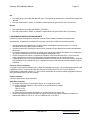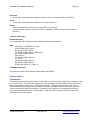
1
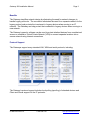
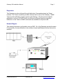
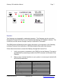
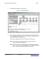
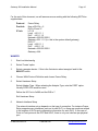
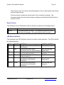
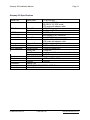
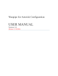
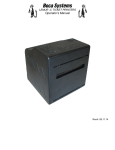
Gateway 900 Installation Manual NOTICE Specifications described in this manual are subject to change without notice. Revision Level: 5.0 Revision Date: 1/3/2004 © Copyright 2004 by JBM Electronics Co. For further information, contact: JBM Electronics Co. 4645 LaGuardia St. Louis, MO 63134 (314) 426-7781 Fax: (314) 426-0007 Website: © JBM Electronics Co. http://www.jbmelectronics.com 1-800-489-7781 www.jbmelectronics.com Gateway 900 Installation Manual Page 1 Overview JBM Electronics' Gateways are low-cost routers designed for users who need to interface Legacy protocol devices to a Frame Relay network. The Gateway 900 (G900) provides one serial port, a 10/100BaseT port and a WAN port with an integrated T1/E1 DSU Converts data from a TCP/IP device to UDP for Ethernet networks. The Gateways convert Legacy protocols to TCP/IP or UDP for connection to a Frame Relay network. The Gateways can also interface IP-only devices to a Legacy protocol network. Terminal emulation for the IP device is available, providing a unique migration path for a network. This capability allows an IP device to coexist with an older protocol network. Offers RIP, OSPF and BPG routing for IP data. Applications Concentrates multiple Legacy protocol applications from one location without replacing existing devices. Existing applications are supported with protocol conversion; data format manipulation, text manipulation, custom data translation, unique network addressing, or specialized host or terminal messaging. The Gateways offer several advantages in customer networks, including: Converts data from Legacy protocol devices to TCP for connection to a WAN network, providing a migration path to an IP-based network. Allows TCP/IP devices to access a Legacy protocol network. Provides host and terminal emulation for all polled protocols, which allows up to 100 physical devices to be connected to one serial port. © JBM Electronics Co. 1-800-489-7781 Provide secure communications with optional Firewall, SSL, IPSec encryption and VPN tunneling software. Provides full Frame Relay support and complete control over the frame network interface, including Priority and CIR allocation. Provides special support software for ATMs and POS devices to enhance error reporting and recovery. Offers custom modifications to handle unique user requirements, such as text or data manipulation, special login commands, host application messages, or data translations. www.jbmelectronics.com Gateway 900 Installation Manual Page 2 Benefits The Gateway simplifies network design by eliminating the need for network changes to handle Legacy protocols. The conversion eliminates the need for a separate network for the legacy protocol and protects the investment in Legacy devices when moving to an IP network. The Gateway can help protect the investment in Legacy devices when moving to a new network. The Gateway’s security software can be used to protect attached devices from unauthorized access or establish a Virtual Private Network (VPN) to connect separate locations into a secure network using Internet connections. Protocol Support The Gateways support many standard LAN, WAN and serial protocols, including: The Gateway’s protocol support includes local polling (spoofing) of attached devices and Client and Server support for the IP protocols. © JBM Electronics Co. 1-800-489-7781 www.jbmelectronics.com Gateway 900 Installation Manual Page 3 Diagnostics The Gateways can be configured through Application Commands entered via Telnet interface. The Telnet connection provides command and control of the Gateway. SNMP Traps provide notification of major events in the Gateway. All of the protocol-specific diagnostics, such as LUSTATS, Notify, and Status and Sense Bytes are supported. Extensions to the Telnet or SNMP commands are available as a special order. Network Diagram This drawing illustrates a configuration using a G900. All of the Gateways provide the same IP connectivity; the only difference is the number of serial and Ethernet devices that can be attached. © JBM Electronics Co. 1-800-489-7781 www.jbmelectronics.com Gateway 900 Installation Manual Page 4 The Gateways can be ordered with Frame Relay connections using an internal or external DSU. The Gateway 700 provides the same port configuration as the G900 but uses an external DSU. The Gateway 800 provides an integrated 56/64/72 KB DSU. With the frame connection, the Gateways provide a complete router replacement with full protocol conversion. Frame Relay Support The Gateway provides full support for Frame Relay networks, including: Supports up to 100 Logical Channels (DLCIs). Both CPE and Access Node configurations. ANSI T1.617 Annex D, Q.933 or LMI Local Signaling. Frame Size to 4096 Bytes. Flow control using individual Committed Information Rate (CIR) for each DLCI. Our Frame Relay support is certified to ISO and ITU standards by major network laboratories. The X.25 support is certified to European NET2 standards by the ROLAND Laboratory. © JBM Electronics Co. 1-800-489-7781 www.jbmelectronics.com Gateway 900 Installation Manual Page 5 Installation The manuals used with the Gateways are: Manual Installation Setup Operations Cables Usage Unpacking and installing the Gateway Defining the Gateway’s configuration Controlling the Gateway Cable Wire Lists The Setup and Operations Manuals are on the CD supplied with the Gateway. 1. Remove the JBM Electronics Gateway 900 from the shipping carton. 2. Inspect the Gateway for shipping damage. If any damage is found, retain the carton and contact the carrier. 3. Connect the cables according to the following table: Port Port 0 Port 1 Port 2 Port 5 4. Description Connector Ethernet Port - supports IP protocols on a 10/100BaseT RJ-45 port. Serial Port - supports Legacy protocols at speeds up to 56 DB-25 KB. The serial interface is RS-232C DCE with DTE Enabled through a cable adapter (G50-adapter). WAN Port - supports Frame Relay or X.25 at speeds up to RJ-45 T1/E1 through the integrated DSU. Console Port (on back) – supports async at 115.2 KB. The DE-9 serial interface is RS-232C DTE with DCE selectable through a cable adapter. Connect the Ethernet cable to the Ethernet port (Port 0). Verify the cable is connected to a network. WARNING: RJ-45 Ports. These are shielded RJ-45 data sockets. They cannot be used as standard traditional telephone sockets, or to connect the unit to a traditional PBX or public telephone network. Only connect RJ-45 data connectors, network telephony systems, or network telephones to these sockets. Either shielded or unshielded data cables with shielded or unshielded jacks can be connected to these data sockets. © JBM Electronics Co. 1-800-489-7781 www.jbmelectronics.com Gateway 900 Installation Manual Page 6 AVERTISSEMENT: Points d’accès RJ-45. Ceux-ci sont protégés par des prises de données. Ils ne peuvent pas êntre utilisés comme prises de téléphone conventionnelles standard, ni pour la connection de l’unité à un réseau téléphonique central privé ou public. Raccorder seulement connecteurs de données RJ-45, systèmes de réseaux de téléphonie ou téléphones de réseaux à ces prises. Il est possible de raccorder des câbles protégés ou non protégés avec des jacks protégés ou non protégés à ces prises de données. 5. Connect the serial cable from the computer to the DB-25 port (Port 1). If the Gateway will be connected to a modem, then the special DTE Cable (JBM Electronics part number G50-Adapter) must be used. The RS-232C cable and adapter are listed in the Cables Manual on the CD supplied with the unit. 6. Connect the phone cable to the WAN Port (Port 2). 7. Plug the Gateway into a power outlet. 8. Configure the Gateway through a stand-alone Configuration Program. This program builds a configuration file that is subsequently transferred to the Gateway. Information and operating instructions for the Configuration Program are available in the Configuration Program Manual. Refer to this manual for instructions to create and transfer the configuration file. 9. Transfer the configuration file to the Gateway using the instructions in the Setup Program Manual. 10. Configure the WAN interface (Page 10) with the integrated console application. Instructions for accessing the console port are available on Page 7. 11. The Gateway is now ready for use. © JBM Electronics Co. 1-800-489-7781 www.jbmelectronics.com Gateway 900 Installation Manual Page 7 Operation The Gateways are designed for unattended operation. The Gateways can be controlled through the Console Port (Port 5) or via Telnet (if the Gateway’s IP Address is known). The connection provides access through a variety of Application Commands. The JBM Operations Manual provides further information on the operation of the Gateway, including Command Line instructions, JBM Administrative Menu and other features. Follow these instructions to access the Gateway through the Console Port: 1. Verify your system is connected to the COM Port on the Gateway. This can be accomplished by connecting a cable to the DE-9 connector on the back of the Gateway. 2. Start an async terminal emulator on your system or use an async terminal with the following parameters: Parameter Protocol Type Port Baud Rate Data Bits Parity Stop Bits Flow Control Emulation Type © JBM Electronics Co. Value Serial Com 1 or Com 2 9600 8 None 1 RTS/CTS VT100 1-800-489-7781 www.jbmelectronics.com Gateway 900 Installation Manual 3. Page 8 The Gateway will display the Login Screen. Screen 1 – Initial Login Screen 4. Once this screen is displayed, Log in to the Gateway using root for the user name and gateway for the password. These entries are case sensitive and must be entered in the appropriate case. This userid and password is used for Console and Telnet access. Note: We recommend you change password using the instructions in the Gateway Operations Manual. Note: Password security for the JBM Application is disabled as a shipment default. This security can be enabled through the JBM Administration Menu. Refer to the Operations Manual for instructions. © JBM Electronics Co. 1-800-489-7781 www.jbmelectronics.com Gateway 900 Installation Manual Page 9 Configure the WAN interface Instructions for configuring the WAN interface are available through the console: - Readme.config (configuring IP over frame) Wanpipe Configuration.pdf (general overview) Wanpipe Configuration Before starting WANPIPE, a configuration file (wanpipeN.conf, where N=1,2,3..etc.) must be created in /etc/wanpipe directory. This file contains the line, hardware and interface definitions for the WAN connection. The program /usr/sbin/wancfg should be used to create the configuration file(s). It is a GUI, ncurses based, configurator that contains all wanpipe options as well as extended help information on each option. Things you should know before starting /usr/sbin/wancfg: Protocol Frame Relay CHDLC PPP X.5 T1/E1 CSU/DSU 56K CSU/DSU © JBM Electronics Co. IP Information Type of Status Signaling (LMI, ANSI, or Q.933) DLCI numbers IP info for each DLCI IP info IP info Maximum packet size Number of SVCs/PVCs IP info Encoding Framing Active Channels/Baud Rate N/A 1-800-489-7781 www.jbmelectronics.com Gateway 900 Installation Manual Page 10 For the rest of this document, we will assume we are working with the following ISP/Telco supplied data: Protocol: Prot Info: IP Info: Frame Relay Num of DLCI's = 2 DLCI=16 and 17 LCI 16 Local =201.1.1.1 PtoP =201.1.1.2 Netmask =255.255.255.0 Gateway =201.1.1.2 (i.e. this is the system default gateway) DLCI 17 Local =202.1.1.1 PtoP =202.1.1.2 Netmask =255.255.255.0 Gateway =N/A WANCFG 1. Start /usr/sbin/wancfg 2. Select 'Create' option 3. Select a wanpipe device. If this is the first device select wanpipe1 and hit the SELECT button. 4. Choose WAN Protocol Definition and choose Frame Relay. 5. Select Hardware Setup Select Adapter Type. When selecting the Adapter Type, note the PORT option. Usually PORT=PRI would be used. Define the I/O Port to 0x280 and the IRQ to 7. Exit Hardware Setup 6. Network Interface Setup The network interface set-up depends on the type of connection. For instance Frame Relay supports many interfaces, each on its own DLCI, so there are questions related to the number of DLCIs and configuration information for each DLCI. In the case of Point-to-Point protocols like PPP and HDLC, there is only one interface per physical port. © JBM Electronics Co. 1-800-489-7781 www.jbmelectronics.com Gateway 900 Installation Manual Page 11 This example is Frame Relay with two DLCIs. The first input is: "Please specify the number of DLCIs supported on this Frame Relay connection" Enter in number 2 For each network interface do the following: - DLCI Number: Enter in the DLCI number. Note the default number is always 16. - Interface Name: The Interface name will also have default value. You can leave it as is or change it. For instance, you could change it to ?chicago? or ?toronto?. IMPORTANT: If you are using iptables you might want to change the default interface name to something like "wan0". Iptables and Ipchains don't like "_" in interface name. e.g.: 'iptables -o wp1_fr16 ...' will give you an error 7. - Operation Mode: WANPIPE is for IP Routing API is used for custom API applications. - DLCI Protocol Setup: In this section leave everything as default. Unless the ISP has specified specific protocol options such as CIR. - IP Setup: Put in your IP info as supplied by ISP Enable Default gateway for the first interface. Once all network interfaces are setup keep hitting the BACK button until Main Menu is reached. Then select EXIT and save the config file. The new config file will be located in /etc/wanpipe directory. 8. Start the device: wanrouter start wanpipe1 Note: The card doesn't have to be connected to start the wanrouter. 9. Troubleshooting the driver load process All wanpipe driver events will be recorded in /var/log/messages. © JBM Electronics Co. 1-800-489-7781 www.jbmelectronics.com Gateway 900 Installation Manual Page 12 Thus if errors occur, first check /var/log/messages to find out what exactly went wrong with the drivers startup. Once the device is started you should see a "link connecting" message. This message indicates that the card was been configured successfully and that the link is trying to connect. Reset Function The Gateways have a Reset Button that can be used to perform the following function: Function Restart Action Press and release the switch. The Gateway will clear its buffers and restart the program. All current sessions will be closed. LED Status Indicators The Gateways have LED indicators that can be used to isolate problems. The LEDs indicate the following activity: LED Power COLOR Yellow TD Red RD Green Link Green Transmit Red Receive Green © JBM Electronics Co. FUNCTION Signifies that power is available to the Gateway Indicates that data is being transmitted from the attached device Indicates that data is being received from the attached device Indicates there is a Link with the Ethernet network. Indicates that data is being transmitted to the Ethernet connection. Indicates that data is being transmitted by the Ethernet connection. 1-800-489-7781 NORMAL STATUS Always On Blinks during data transmission Blinks during data reception On when connected Blinks during data transmission Blinks during data reception. www.jbmelectronics.com Gateway 900 Installation Manual Page 13 Gateway 900 Specifications Serial Port: WAN Port: LAN Port: Console Port: Management: LED Indicators: Power: Physical: Processor: Memory: Warranty: © JBM Electronics Co. Baud Rate: Interface: 110-56,000 bps One Female DB-25 connector RS-232C/V.35, DCE mode, DTE mode with adapter cable Baud Rate: T1/E1 DSU Interface: One Female RJ-45 connector Ethernet: 10/100BaseT One Female RJ-45 connector Baud Rate: Up to 115,200 bps Interface: One Male DE-9, RS-232C DTE mode DCE mode with adapter cable Console Port: CLI Access through async connection IP Protocol SNMP and Telnet Serial Port(s): TD and RD (each port) WAN Port: TD and RD LAN Port: Link, Transmit, Receive (each port) Power: On/Off State 120-240 VAC, 50/60 Hz (Internal) Size: 6.5" W x 3.5" H x 10" L Weight: 5 pounds 486DX-100 32 MB RAM, 128 K BRAM, 16MB Flash 1 Year Parts and Labor 1-800-489-7781 www.jbmelectronics.com Gateway 900 Installation Manual Page 14 SAFETY INFORMATION Please read the following safety information carefully before installing the Gateway. WARNING: Installation and removal of the unit must be carried out by qualified personnel only. The unit must be connected to an earthed (grounded) outlet to comply with international safety standards. Do not connect the unit to an A.C. outlet (power supply) without an earth (grounded) connection. If the Gateway is provided with an IEC320 plug, the appliance coupler (the connector to the unit and not the wall plug) must have a configuration for mating with an EN60320/IEC320 appliance inlet. The socket outlet must be near to the unit and easily accessible. You can only remove power from the unit by disconnecting the power cord from the outlet. This unit operates under SELV (Safetly Extra Low Voltage) conditions according to IEC 60. The conditions are only maintained if the equipment to which it is connected also operates under SELV conditions. France and Peru only This unit cannot be powered from IT† supplies. If your supplies are of IT type, this unit must be powered by 230V (2P+T) via an isolated transformer ration 1:1, with the secondary connection point labeled Neutral, connected directly to earth (ground). † Impédance â la terre Power Cord Set This must be approved for the country where it will be used, for example: U.S.A. and Canada The cord set must be UL-approved and CSA certified. The minimum specifications for the flexible cord are: No. 18 AWG Type SV or SJ 3-conductor The cord set must have a rated current capacity of as least 10A. The attachment plug must be an earth-grounding type with a NEMA 5-15P (15 A, 125 V) or NEMA 6-15P (15 A, 250 V) configuration. Denmark The supply plug must comply with Section 107-2-D1, Standard DK2-1a or DK2-5a. Switzerland The supply plug must comply with SEV/ASE 1011. © JBM Electronics Co. 1-800-489-7781 www.jbmelectronics.com Gateway 900 Installation Manual Page 15 UK The supply plug must comply with BS1363 (3-pin 13-amp) and be fitted with a 5 A fuse which compiles with BS1362. The main cords must be <HAR> or <BASEC> marked and be of type HO3VVF3G0.75 (minimum). Europe The supply plug must comply with CEE7/7 (“SCHUKO”) The main cords must be <HAR> or <BASEC> marked and be of type HO3VVF3G0.75 (minimum). L’INFORMATION DE SÉCURITÉ IMPORTANTE Veuillez lire à fond l’information de la sécurité suivante avant d’installer le Baseline Dual Speed Hub. Avertissement: L’installation et la dépose de ce groupe doivent être confiés à un personnel qualifié. Ne branchez pas votre appaireil sur une prise secteur (alimentation électrique) lorsqu’il n’y a pas de connexion de mise à la terre (mise à la masse). Vous devez raccorder ce groupe à la terre (mise à la masse) afin de respecter les normes internationales de sécurité. Le coupleur d’appareil (le connecteur du goupe et non pas la prise murale) doit repecter une configuration qui permet un branchement sur une entrée d’appareil EN60320/IEC 320. La prise secteur doit se trouver à proximité de l’appareil et son accès doit être facile. Vous ne pouvez mettre l’appareil hors circuit qu’en dèbranchant son cordon électrique au niveau de cette prise. L’appaireil fonctionne à une tension extrêmement basse de séciroté qui est conforme à la norme IEC60950. Ces conditions ne sont maintenues que si l’equipement auquel el est raccordé fonctionne dans les mêmes conditions. France et Pérou uniquement: Ce groupe ne peut pas être alimenté par un dispositif à impédance à la terre. Si vos alimentations sont du type impédance à la terre, ce groupe doit être alimenté par une tension de 230 V (2 P+T) par le biais d’un transformateur d’isolement à rapport 1:1, avec un point secondaire de connesion portant l’appellation Neutre et avec raccordement direct à la terre (masse). Cordon électrique Il doit être agréé dans le pays d’utilisation. Etats-Unis et Canada Le cordon doit avoir reçu l’homologation des UL et un certificat de la CSA. Le cordon souple doit respecter, à titre minimum, les spécifications suivantes: Calibre 18 AWG Type SV ou SJ à 3 conducteurs La cordon doit être en mesure d’acheminer un courant nominal d’au moins 10A. La prise femelle de branchement doit être du type à mise à la terre (mise à la masse) et respecter la configuration NEMA 5-15P (15 A, 125 V) ou NEMA 6-15P (15 A, 250 V). © JBM Electronics Co. 1-800-489-7781 www.jbmelectronics.com Gateway 900 Installation Manual Page 16 Danemark La prise mâle d’alimentation doit respecter la section 107-2 D1 de la norme DK2 1a ou DK2 5a. Suisse La prise mâle d’alimentation doit respecter la norme SEV/ASE 1011. Europe La prise secteur doit être conforme aux normes CEE 7/7 (“SCHUKO”) Le cordon secteur doit porter la mention <HAR> ou <BASEC> et doit être de type H03VVF3GO.75 (minimum). Technical Information Related Standards The Gateway 900, 905 and 910 have been designed to the following standards: EMC FCC PART 15, SUBPART B, Class A CISPR 22/EN 55022, Class A IEC 61000-4-2/EN 61000-4-2 IEC 61000-4-3/EN 61000-4-3, ENV 50204 IEC 61000-4-4/EN 61000-4-4 EN 61000-4-5 IEC 61000-4-6/EN 61000-4-6 ITU-T-K.20 IEC 61000-3-2/EN 61000-3-2 IEC 61000-3-3/EN 61000-3-3 ETSI EN 300 386 V1.2.1 (1998-11) CE Statement (Europe) This product complies with the European EMC Directive 89/336/EEC. Regulatory Notices FCC Statement This equipment has been tested and found to comply with the limits for a Class A digital device, pursuant to part 15 of the FCC rules. These limits are designed to provide reasonable protection against harmful interference when the equipment is operated in a commercial environment. This equipment generates, uses and can radiate radio frequency energy; and if not installed and used in accordance with the instructions, may cause harmful interference to radio communications. Operation of this equipment in a residential area is likely to cause harmful interference to radio communications, in which case the user will be required to correct the interference at their own expense. © JBM Electronics Co. 1-800-489-7781 www.jbmelectronics.com Gateway 900 Installation Manual Page 17 Information To The User If this equipment does cause interference to radio or television reception, which can be determined by turning the equipment off and on, the user is encouraged to try to correct the interference by one or more of the following measures: Reorient the receiving antenna. Relocate the equipment with respect to the receiver. Move the equipment away from the receiver. Plug the equipment into a different outlet so that equipment and receiver are on different branch circuits. If necessary, the user should consult the dealer or an experienced radio/television technician for additional suggestions. The user may find the following booklet prepared by the Federal Communications Commission helpful: How to Identify and Resolve Radio-TV Interference Problems This booklet is available from the U.S. Government Printing Office, Washington, DC 20402, Stock No. 004-00000345-4. In order to meet FCC emissions limits, this equipment must be used only with cables with comply with IEEE 802.3. CSA Statement This Class A digital apparatus meets all requirements of the Canadian Interference-Causing Equipment Regulations. Cet appareil numérique de la classe A respecte toutes les exigences du Règlement sur le matérial brouilleur du Canada. Warranty JBM Electronics provides a limited warranty for the Gateway, which consists of the following: ♦ This warranty is effective for one year from the delivery date of the Gateway to the purchaser. ♦ The purchaser is responsible for returning the defective unit to our factory, freight prepaid. ♦ If the Gateway is under warranty, we will repair it at our cost and return it, freight prepaid, via UPS ground service. ♦ If the Gateway is not covered by the warranty, we will notify you of the repair charges. We will not repair the Gateway without your permission. ♦ All repairs are guaranteed for 90 days or the remainder of the warranty, whichever is longer. © JBM Electronics Co. 1-800-489-7781 www.jbmelectronics.com Gateway 900 Installation Manual Page 18 Except for the express warranty set forth herein, JBM Electronics Co. grants no warranties, either express or implied, of merchantability and fitness. The stated express warranty is in lieu of all liabilities or obligations of JBM Electronics Co. for damages including but not limited to consequential damages occurring out of or in connection with the delivery, use or performance of JBM products. Buyer's remedies for breach of warranty shall be limited to repair or replacement subject to adjustment as stated herein, or full or partial adjustment to purchase price. Software Terms Software supplied with each JBM Electronics' product remains the exclusive property of JBM Electronics. JBM grants with each unit a perpetual license to use this software with the express limitation that the software may not be copied or used in any other product for any purpose. It may not be reverse engineered, or used for any other purpose other than in and with the computer hardware sold by JBM Electronics. Extended Warranty Program JBM offers an extended warranty for the Gateway. This program extends the original warranty on a yearly basis. In addition to extending the original warranty, the emergency replacement program is included for the cost of freight only. The extension must be purchased before the original warranty expires. Please contact JBM Electronics for further information. Return for Repair If you want us to repair the Gateway, contact JBM for a Return Authorization Number (RA). Once you have the RA number, carefully pack the defective unit, and return it freight prepaid. Do not use Parcel Post. Repair charges are a flat fee for units outside of the warranty. Please include a letter with the RA number, your name and address, and details of the difficulty experienced. The letter is important since the shipping material is discarded. Units should be sent to: JBM Electronics Co. 4645 LaGuardia St. Louis, MO 63134 Attention: RA # © JBM Electronics Co. 1-800-489-7781 www.jbmelectronics.com