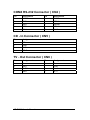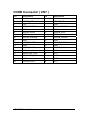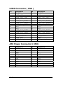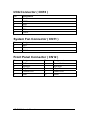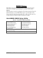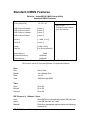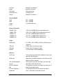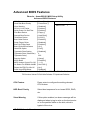
1
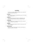
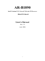
AR-B1890
Intel® Pentium® M / Celeron® M Socket 478 Processor
Mini-ITX Board
User’s Manual
Rev. 1.0
June. 2006
0
Copyright
The trademarks mentioned in the manual are legally registered to their
respective companies.
Notice
The written content provided with this product in the property of Acrosser. No
part of this manual may be reproduced, copied, transmitted in any form or by
any means without prior written permission of Acrosser.
Manual Classification
In order to assist in the use of this product, Acrosser has categorized the user
manual. For detailed product information and specifications, please carefully
read the “ Product User Manual ”.
AR-B1890 User’s Manual
1
Packing List
Please make sure that the following materials before you start installing your
board.
☆ AR-B1890 board
☆ Quick Installation Guide
☆ CD for manual and drivers
☆ Cable Kit ( CPU cooler, IDE cable, Serial ATA cable, Serial Port cable,
Slim type floppy cable, I/O Shield )
AR-B1890 User’s Manual
2
Table Of Contents
General Information
Introduction
5
Specification
6
Block Diagram
8
Mechanical Drawing………………………………………………... 9
Hardware Installation
Connectors Location
List of Connectors
Jumpers Locations
List of Jumpers
Jumpers Setting
11
13
14
14
Front Panel Connector ( CN12 )
GPIO Connector ( CN13 )
CPU Fan Connector ( CN14 )
PS2 KB/ MS Connector ( PS2-KBMS1 A / B )
EIDE Connector ( IDE1 )
USB Connector ( USB1 )
21
22
22
22
23
15
LVDS Panel Voltage Selection ( JP3 )
15
Clear CMOS Selection ( JP5 )
15
COM2 RS232/422/485 Slection ( JP6, JP7 )…………………….16
VGA Display / Audio Connector ( CN1 )
17
5.1 Channel Audio Connector ( CN2 )
17
COM 3 RS-232 Connector ( CN3 )
17
COM4 RS-232 Connector ( CN4 )
18
CD - In Connector ( CN5 )
18
18
TV - Out Connector ( CN6 )
DVOB Connector ( CN7 )
19
LVDS Connector ( CN8 )
20
ATX Power Connector ( CN9 )
20
IrDA Connector ( CN10 )
21
System Fan Connector ( CN11 )
21
Slim Floppy Connector ( FDD1 )
COM1 RS-232 Connector ( COM1 )
COM2 RS-232 / 422 / 485 Connector ( COM2 )
AR-B1890 User’s Manual
3
23
24
24
24
Gigabit LAN / USB Connector ( RJUSB1 )
Ethernet LAN / USB Connector ( RJUSB2 )
Mini - PCI Slot ( MPCI1 )
CompactFlash Slot ( CFD1 )
SoDIMM Slot ( DIMM1 )
SoDIMM Slot ( DIMM 2 )
SATA1 Connector ( SATA1 )
SATA2 Connector ( SATA2 )
PCI - Express Slot ( PCIE1 )
25
25
25
25
25
25
25
25
25
BIOS Setup
AwardBIOS CMOS Setup Utility………………………………….. 26
Standard CMOS Features………………………………………….27
Advanced BIOS Features…………………………………………. 29
Advanced Chipset Features………………………………………. 32
Integrated Peripherals………………………………………………34
Power Management Setup…………………………………………37
PnP / PCI Configurations………………………………………….. 39
PC Health Status…………………………………………………… 40
Load Fail – Safe Defaults…………………………………………. 41
Load Optimized Defaults………………………………………….. 41
Set Supervisor / User Password…………………………………. 41
Save & Exit Setup………………………………………………….. 41
Exit Without Saving………………………………………………… 41
Drivers Installation
Install Chipset Drivers……………………………………………… 42
Install VGA drivers…………………………………………………. 42
Install AC97 Codec Audio Drivers………………………………… 42
Install Marvell GigaLAN Drivers………………………………….. 42
Install Realtek Ethernet Drivers……………………………………42
AR-B1890 User’s Manual
4
General Information
Introduction
The AR-B1890 Mini – ITX board incorporates the Intel® 915GM Express and
Intel® I / O controller Hub ICH6 - M chipset , supports the Intel® Pentium® M /
Celeron® M processors with 533 / 400 MHz Front Side Bus ( FSB ), Intel®
Graphics Media Accelerator 900 ( Intel® GMA 900 ), DDRII 533 MHz system
memory, PCI - Express interface, Ethernet / Gigabit LAN, Realtek Audio, LVDS,
CompactFlash, Mini – PCI, Serial ATA, USB 2.0.
Multimedia Applications
For multimedia application solution, Intel® 915GM Express and ICH6 – M
chipset provides on board high performance graphics, 18 – bit LVDS interface,
HDTV TV – Out and Audio function. This feature will be good of use in very
requirement of the multimedia application.
Widely Expanded Interface
The board provides PCI – Express x 1 slot, you can add a third LAN port, 6 ~ 8
COM Port, and also provides Mini – PCI slot and CompactFlash Type II slot.
AR-B1890 User’s Manual
5
Specification
Board
AR-B1890
CPU
Up to Intel® Pentium M 2.26G ( 400 / 533MHz
FSB ) Celeron® M 1.6G ( 400MHz FSB )
Chipset
Intel® 915GM Express chipset + ICH6 - M
Memory
DDR II SoDIMM slot support up to 2GB memory
Support dual channel DDR II 400 / 533 SoDIMM
VGA
Built in Intel® 915GM GMCH Express chipset
I / O Control
Intel® ICH6 – M + ITE 8712 + Fintek F81216D
LAN
1 Realtek RTL8100C 10 / 100Mbit LAN
1 Marvell 88E8053 10 / 100 / 1000Mbit LAN
Audio
Intel® ICH6 – M with Realtek ALC655 Codec
IDE
UDMA 33 / 66 / 100 ATA IDE connection
FDD
1 Slim FDD connection
SATA
2 Serial ATA ports
Slot
1 Mini – PCI slot
1 CompactFlash slot
1 PCI – Express x 1 slot
BIOS
Phoenix – Award 4Mb PnP Flash
GPIO
8 – bit digital I / O
Green Function
ACPI 1.0 and APM 1.2 compliant
Watchdog Timer
System reset programmable watchdog timer with 1
~ 255 Min. of time - out
H / W Monitoring
ITE 8712 support power supply voltage and
temperature monitoring functions
Real Time Clock
Intel® ICH6 – M built – in RTC with Lithium battery
Form Factor
Mini – ITX 6.69 “( L ) x 6.69” ( W ) / 17 x 17 mm
VGA Display
Chipset
Intel® 915GM GMCH Express chipset
Memory
Shared system memory up to 128MB
Display
CRT / LCD monitor with analog for 18 – bit dual
channel LVDS interface
TV-OUT
Support PAL/NTSC
AR-B1890 User’s Manual
6
I / O Ports
Keyboard/ Mouse
1 PS / 2 ports
Serial
2 internal RS - 232 ports ( COM 3 / 4 )
1 external RS – 232 port ( COM 1 )
1 external RS – 232 / 422 / 485 port ( COM 2 )
VGA
1 VGA port
Audio
1 external jack for MIC – In / Line – In / Line – Out
LAN
2 external RJ – 45 ports with LED
USB
2 internal USB 2.0 ports
4 external USB 2.0 ports
Power And Environment
POWER
ATX power connector
TEMPERATURE
Operating temperature with 0°C~60°C
(32°F~140°F)
Storage temperature with 20°C~80°C
(-68°F~176°F)
AR-B1890 User’s Manual
7
Block Diagram
Intel Pentium-M ITX Board
Dothan/Yonah
Processor
IMVP-IV VR
CK-410M
478 uFCPGA
B
S
F
CRT
DDR2
Modules
400/533MHz
R/B/G
Intel 82915GM
LVDS
TV-OUT
18 Bit LVDS
TVOUT
PCI-E 1X
PCI-E
SATA X 2
SATA
Realtek
ALC655
I
M
D
Intel 82801FBM
IDE X 1
5.1 Channels
Marvell
88E8053-A2-NNC
LAN1
RealTek
RTL8100C/8110S
LAN2
PATA
609 BGA
CFD X 1
USB2.0 X 6
SDVO
Connector
PCI-E Gfx / SDVO
1257 FCBGA
USB2.0
MiniPCI
SLOT
FWH
LPC
Ver-G NT:69
Ver-I NT:55
NT:38
KB & MS
FINTEK
F81216D
ITE8712F
Digital I/O
Slim FDC
IRDA
COM1
COM3
COM2
AR-B1890 User’s Manual
8
COM4
Mechanical Drawing
Component side
AR-B1890 User’s Manual
9
Solder Side
AR-B1890 User’s Manual
10
Hardware Installation
Connectors Location
Component Side
AR-B1890 User’s Manual
11
Solder Side
I / O Panel
AR-B1890 User’s Manual
12
List of Connectors
Connector
Function
CN1
VGA Display / Audio Connector
CN2
Front Audio Connector
CN3
COM 3 RS-232 Connector
CN4
COM4 RS-232 Connector
CN5
CD - In Connector
CN6
TV - Out Connector
CN7
DVOB Connector
CN8
LVDS Connector
CN9
ATX Power Connector
CN10
IrDA Connector
CN11
System Fan Connector
CN12
Front Panel Connector
CN13
GPIO Connector
CN14
CPU Fan Connector
PS2-KBMS1 A / B
PS2 Keyboard / Mouse Connector
FDD1
Slim Floppy Connector
IDE1
EIDE Connector
COM1
COM1 RS-232 Connector
COM2
COM2 RS-232 / RS-422 / RS-485 Connector
RJUSB1 A / B
Gigabit LAN / USB Connector
RJUSB2 A / B
Ethernet LAN / USB Connector
USB1
USB1 Connector
USB2
USB2 Connector
MPCI1
Mini - PCI Slot
CFD1
CompactFlash Slot
DIMM1
SoDIMM Slot
DIMM2
SoDIMM Slot
SATA1
SATA1 Connector
SATA2
SATA2 Connector
PCIE1
PCI - Express Slot
AR-B1890 User’s Manual
13
Jumpers Locations
List of Jumpers
JP3
LVDS Panel Voltage Selection ( +5V / +3.3V )
JP5
Clear CMOS Selection
JP6
COM2 RS232/422/485 Select
JP7
COM2 RS232/422/485 Select
AR-B1890 User’s Manual
14
Jumpers Setting
OPEN 1 - 2 - 3
SHORT
1-2
SHORT
2-3
□
○
○
■
●
○
□
●
●
1
2
3
1
2
3
1
2
3
LVDS Panel Voltage Selection ( JP3 )
5V
1 □
3.3V
○ 2
2 ●
● 3
Clear CMOS Selection ( JP5 )
Protected
1 ■
● 2
Clear CMOS
2 ○
AR-B1890 User’s Manual
○ 3
15
COM2 RS232/422/485 Selection ( JP6,JP7 )
COM2 SETTING RS232
JP6
JP7
1 ■
● 2 3 ○
1 ■
● 2
4 ●
● 5 6 ○
3 ○
○ 4
7 ●
● 8 9 ○
5 ○
○ 6
10 ●
● 11 12 ○
COM2 SETTING RS422
JP6
JP7
1 □
2 ●
● 3
1 □
○ 2
4 ○
5 ●
● 6
3 ●
● 4
7 ○
8 ●
● 9
5 ○
○ 6
10 ○ 11 ●
● 12
COM2 SETTING RS485
JP6
JP7
1 □
2 ●
● 3
1 □
○ 2
4 ○
5 ●
● 6
3 ○
○ 4
7 ○
8 ●
● 9
5 ●
● 6
10 ○ 11 ●
● 12
AR-B1890 User’s Manual
16
VGA Display Connector ( CN1 )
Pin
Assignment
Pin
Assignment
1
RED
2
GREEN
3
BLUE
4
N/C
5
GND
6
GND
7
GND
8
GND
9
VGA_VCC
10
GND
11
N/C
12
CRT _ DDCDATA
13
HSYNC
14
VSYNC
15
CRT_DDCCLK
5.1 Channel Audio Connector ( CN2 )
Pin
Assignment
Pin
Assignment
1
LOUT _ R
2
LOUT _ L
3
GND
4
GND
5
SURROUND _ R
6
SURROUND _ L
7
GND
8
GND
9
LFE _ O
10
CEN _ O
11
GND
12
GND
13
SPDIF _ O
14
SPDIF _ I
COM 3 RS-232 Connector ( CN3 )
Pin
Assignment
Pin
Assignment
1
DCD3#
2
RXD3
3
TXD3
4
DTR3#
5
GND
6
DSR3#
7
RTS3#
8
CTS3#
9
RI3#
10
N/C
AR-B1890 User’s Manual
17
COM4 RS-232 Connector ( CN4 )
Pin
Assignment
Pin
Assignment
1
DCD4#
2
RXD4
3
TXD4
4
DTR4#
5
GND
6
DSR4#
7
RTS4
8
CTS4#
9
RI4#
10
N/C
CD - In Connector ( CN5 )
Pin
Assignment
1
CD-L
2
GND
3
GND
4
CD-R
TV - Out Connector ( CN6 )
Pin
Assignment
Pin
Assignment
1
Y
2
C
3
GND
4
GND
5
CVBS
6
N/C
7
GND
8
N/C
AR-B1890 User’s Manual
18
DVOB Connector ( CN7 )
Pin
Assignment
Pin
Assignment
1
5V
2
3.3V
3
SDVOB_INT#
4
SDVOB_INT
5
2.5V
6
GND
7
SDVO_FLDSTALL#
8
SDVO_FLDSTALL
9
GND
10
GND
11
SDVOB_RED#
12
SDVOB_RED
13
GND
14
GND
15
SDVOB_GREEN#
16
SDVOB_GREEN
17
GND
18
GND
19
SDVOB_BLUE#
20
SDVOB_BLUE
21
GND
22
GND
23
SDVOB_CLK#
24
SDVOB_CLK
25
GND
26
GND
27
SDVOCTRL_CLK
28
N/C
29
SDVOCTRL_DATA
30
N/C
31
GND
32
GND
33
SDVOB_RST#
34
N/C
AR-B1890 User’s Manual
19
LVDS Connector ( CN8 )
Pin
Assignment
Pin
Assignment
1
BKL _ EN
2
BKL _ CTL
3
LVDS _ VCC
4
GND
5
LVDS _ CH1 _ CLK-
6
LVDS _ CH1 _ CLK+
7
LVDS _ VCC
8
GND
9
LVDS _ CH1 _ DATA0-
10
LVDS _ CH1 _ DATA0+
11
LVDS _ CH1 _ DATA1-
12
LVDS _ CH1 _ DATA1+
13
LVDS _ CH1 _ DATA2-
14
LVDS _ CH1 _ DATA2+
15
N/C
16
N/C
17
N/C
18
N/C
19
LVDS _ CH2 _ DATA0-
20
LVDS _ CH2 _ DATA0+
21
LVDS _ CH2 _ DATA1-
22
LVDS _ CH2 _ DATA1+
23
LVDS _ CH2 _ DATA2-
24
LVDS _ CH2 _ DATA2+
25
LVDS_DDCPDATA
26
LVDS_DDCPCLK
27
LVDS _ VCC
28
GND
29
LVDS _ CH2 _ CLK-
30
LVDS _ CH2 _ CLK+
ATX Power Connector ( CN9 )
Pin
Assignment
Pin
Assignment
1
3.3V
2
3.3V
3
GND
4
5V
5
GND
6
5V
7
GND
8
N/C
9
5VSB
10
12V
11
3.3V
12
-12V
13
GND
14
PSON
15
GND
16
GND
17
GND
18
-5V
19
5V
20
5V
AR-B1890 User’s Manual
20
IrDA Connector ( CN10 )
Pin
Assignment
1
5V
2
CIRTX
3
IRRX
4
GND
5
IRTX
6
CIRRX
System Fan Connector ( CN11 )
Pin
Assignment
1
GND
2
12V
3
FAN Sense
Front Panel Connector ( CN12 )
Pin
Assignment
Pin
Assignment
1
GND
2
Power Switch
3
BUZZER-
4
BUZZER+
5
HD_LED-
6
HD_LED+
7
POWER LED-
8
Power LED+
9
GND
10
Reset
AR-B1890 User’s Manual
21
GPIO Connector ( CN13 )
Pin
Assignment
1
GPI
2
GPO
3
GPI
4
GPO
5
GPI
6
GPO
7
GPI
8
GPO
9
5V
10
GND
CPU Fan Connector ( CN14 )
Pin
Assignment
1
GND
2
12V
3
FAN Sense
PS2 KB / MS Connector ( PS2-KBMS1 A / B )
Pin
Assignment
Pin
Assignment
1
KB_DATA
2
N/C
3
GND
4
KB_VCC
5
KB_CLK
6
N/C
7
MS_DATA
8
N/C
9
GND
10
KB_VCC
11
MS_CLK
12
N/C
AR-B1890 User’s Manual
22
EIDE Connector ( IDE1 )
Pin
Assignment
Pin
Assignment
1
IDERST#
2
GND
3
PID7
4
PID8
5
PID6
6
PID9
7
PID5
8
PID10
9
PID4
10
PID11
11
PID3
12
PID12
13
PID2
14
PID13
15
PID1
16
PID14
17
PID0
18
PID15
19
GND
20
N/C
21
PDREQ
22
GND
23
PIOR#
24
GND
25
PIOR#
26
GND
27
PRDY
28
GND
29
PACK#
30
GND
31
PIRQ14
32
N/C
33
PPDA1
34
ATA66 _ DET
35
PPDA0
36
PPDA2
37
PPCS1#
38
PPCS3#
39
HDLED#
40
GND
USB Connector ( USB1 )
Pin
Assignment
Pin
Assignment
1
USB_VCC
2
GND
3
USB4-
4
GND
5
USB4+
6
USB5+
7
GND
8
USB5-
9
GND
10
USB_VCC
AR-B1890 User’s Manual
23
Slim Floppy Connector ( FDD1 )
Pin
Assignment
Pin
Assignment
1
VCC
2
INDEX#
3
VCC
4
DRV _ SEL#
5
VCC
6
DSK _ CH#
7
N/C
8
N/C
9
N/C
10
MOTOR#
11
N/C
12
DIR#
13
DENSEL#
14
STEP#
15
GND
16
WDATA#
17
GND
18
WGATE#
19
GND
20
TRACK#
21
GND
22
WPROT#
23
GND
24
RDATA#
25
GND
26
SIDE#
COM1 RS-232 Connector ( COM1 )
Pin
Assignment
Pin
Assignment
1
DCD1#
2
RXD1
3
TXD1
4
DTR1#
5
GND
6
DSR1#
7
RTS1#
8
CTS1#
9
RI1#
COM2 RS-232/422/485 Connector ( COM2 )
Pin
Assignment
1
DCD2#(422TXD-/485DATA-) 2
RXD2(422RXD+)
3
TXD2(422TXD+/485DATA+)
4
DTR2#(422RXD-)
5
GND
6
DSR2#
7
RTS2#
8
CTS2#
9
RI2#
AR-B1890 User’s Manual
Pin
24
Assignment
Gigabit LAN / USB Connector ( RJUSB1 )
Standard RJ - 45 Connector / Standard USB Connector
Ethernet LAN / USB Connector ( RJUSB2 )
Standard RJ - 45 Connector / Standard USB Connector
Mini - PCI Slot ( MPCI1 )
Standard Mini - PCI Connector
CompactFlash Slot ( CFD1 )
Standard CompactFlash Connector Type II
SoDIMM Slot ( DIMM1 )
Standard DDRII SoDIMM Connector
SoDIMM Slot ( DIMM 2 )
Standard DDRII SoDIMM Connector
SATA1 Connector ( SATA1 )
Standard Serial ATA Connector
SATA2 Connector ( SATA2 )
Standard Serial ATA Connector
PCI - Express Slot ( PCIE1 )
Standard PCI – Express x 1 Slot
AR-B1890 User’s Manual
25
BIOS Setup
BIOS (Basic Input and Out System) includes a CMOS Setup utility which
allows user to configure required settings or to activate certain system
features.
When the power is turned on, pushing the <Del> button during the Power-On
Self test will take you to the CMOS Setup screen. If you still wish to enter
Setup, restart the system by pressing the <Ctrl>, <Alt> and <Del> keys. You
can also restart by turning the system Off and back On again.
AwardBIOS CMOS Setup Utility
Phoenix – AwardBIOS CMOS Setup Utility
Standard CMOS Features
Advanced BIOS Features
Advanced Chipset features
Integrated Peripherals
Power Managements
PnP / PCI Configurations
PC Health Status
ESC : Quit
Load Fail – Safe Defaults
Load Optimized Defaults
Set Supervisor Password
Set User Password
Save & Exit Setup
Exit Without Saving
↑↓→← : Select Item
F10 : Save & Exit Setup
Onboard IO, IRQ, DMA Assignment…
AR-B1890 User’s Manual
26
Standard CMOS Features
Phoenix – AwardBIOS CMOS Setup Utility
Standard CMOS Features
Date (mm:dd:yy)
Time (hh:mm:ss)
Thu, Dec 15 2005
10 : 59 : 36
IDE Channel 0 Master
IDE Channel 0 Slave
IDE Channel 1 Master
IDE Channel 0 Slave
[ None ]
[ None ]
[ None ]
[ None ]
Drive A
Drive B
[ 1.44M, 3.5 in ]
[ None ]
Video
Halt On
[ EGA / VGA ]
[ All, But Keyboard ]
Base Memory
Extended memory
Total Memory
Item Help
Menu Level
>
Change the day, month,
year and century
640K
1038336K
1039360K
↑↓→←:Move Enter:Select +/-/PU/PD:Value F10:Save ESC:Exit F1:General Help
F5:Previous Values F6:Fail-Safe Defaults F7:Optimized Defaults
Date
Day
Month
Date
Year
Sun to Sat
Jan. through Dec.
1 to 31
1999 through 2099
Time
Hour
Minute
Second
00 to 23
00 to 59
00 to 59
IDE Channel 0, 1 Master / Slave
Auto
Allow BIOS to automatically detect IDE devices.
None
If no IDE devices are used.
Manual
Enter the appropriate option based on following
information.
AR-B1890 User’s Manual
27
Cylinder
Head
Precomp
Landing Zone
Sector
Number of cylinders
Number of heads
Write precomp
Landing zone
Number of sectors
Access Mode
CHS
LBA
Large
Auto
HD < 528MB
HD > 528MB
For MS-DOS only
Drive A / Drive B
360KB, 5.25”
5.25” inch 360KB PC-type standard drive.
1.2MB, 5.25”
720KB, 3.5”
1.44MB, 3.5”
2.88MB, 3.5”
5.25” inch 1.2MB AT-type high-density drive.
3.5” inch 720KB double-sided drive.
3.5” inch 1.44MB double-sided drive.
3.5” inch 2.88MB double-sided drive.
Video
EGA/VGA
CGA 40
CGA 80
MONO
Halt On
No Errors
All Errors
ALL, But Keyboard
error, it
All, But Diskette
will
All, But Disk/Key
keyboard
AR-B1890 User’s Manual
For EGA, VGA, SEGA, SVGA or PGA monitor
adapters.
Power up in 40 column mode.
Power up in 80 column mode.
For Hercules or MDA adapters.
The system boot will not be halted for any error
that may be detected.
Whenever the BIOS detects a non-fail error the
system will be stopped.
The system boot will not stop for a keyboard
will stop for all other errors.
The system boot will not stop for a disk error, it
stop for all other errors.
The system boot will not stop for a disk or
error, it will stop for all other errors.
28
Advanced BIOS Features
Phoenix – AwardBIOS CMOS Setup Utility
Advanced BIOS Features
CPU Features
Hard Disk Boot Priority
Virus Warning
CPU L1 & L2 Cache
Quick Power On Self Test
First Boot Device
Second Boot Device
Third Boot Device
Boot Other Device
Swap Floppy Driver
Boot Up Floppy Seek
Boot Up NumLock Status
Gate A20 Option
Typematic Rate Setting
Typematic Rate (Chars/Sec)
Typematic Delay
Security Option
APIC Mode
MPS Version Control For OS
Os Select For DRAM >64MB
Report No FDD For Win 95
Small Logo(EPA)Show
[ Press Enter ]
[ Press Enter ]
[ Disabled ]
[ Enabled ]
[ Enabled ]
[ Floppy ]
[ Hard Disk ]
[ LS120 ]
[ Enabled ]
[ Disabled ]
[ Enabled ]
[ On ]
[ Fast ]
[ Disabled ]
6
250
[ Setup ]
[ Enabled ]
[ 1. 4 ]
[ Non-OS2 ]
[ No ]
[ Disabled ]
Item Help
Menu Level
>
↑↓→←:Move Enter:Select +/-/PU/PD:Value F10:Save ESC:Exit F1:General Help
F5:Previous Values F6:Fail-Safe Defaults F7:Optimized Defaults
CPU Feature
Press enter to configure the setting relevant
CPU feature.
HDD Boot Priority
Select boot sequence for on board SCSI, RAID,
etc.
Virus Warning
If this option enabled, an alarm message will be
displayed when trying to write on the boot sector
or on the partition table on the disk, which is
typical of the virus.
AR-B1890 User’s Manual
29
CPU L1&L2 Cache
This option allows you to enable or disable the
cache function.
Quick Power On Self Test
When this option enabled, this field speeds up
the Power On Self Test after the system is
turned on.
First/Second/Third Boot Device
Floppy
Select your boot device priority by Floppy.
LS120
Select your boot device priority by LS120.
Hard Disk
Select your boot device priority by Hard Disk.
CDROM
Select your boot device priority by CDROM.
ZIP
Select your boot device priority by ZIP.
USB-FDD
Select your boot device priority by USB-FDD.
USB-ZIP
USB-CDROM
USB-HDD
LAN
Disabled
Select your boot device priority by USB-ZIP.
Select your boot device priority by
USB-CDROM.
Select your boot device priority by USB-HDD.
Select your boot device priority by LAN.
Disable this function.
Boot Other Device
This option allows the system to search for an
OS from other devices.
Swap Floppy Driver
This option allows you to determine whether or
not to enable Swap Floppy drive.
Boot Up Floppy Seek
This option controls whether the BIOS checks
for a floppy drive while booting up.
Boot Up NumLock Status
This option allows you to activate the NumLock
function after you power up the system.
Gate A20 Option
This option allows you to select how Gate A20 is
worked.
Typematic Rate Setting
When disabled, continually holding down a key
on your keyboard will generate only one
instance. When enabled, you can set the two
typematic controls listed next.
AR-B1890 User’s Manual
30
Typematic Rate (Chars/Sec)
When enabled, the system registers repeated
keystrokes speeds. Setting are from 6 to 30
characters per second.
Typematic Delay
When enabled, this option allows you to set the
time interval for displaying the first and second
characters.
Security Option
When setup, the system always boots up and
prompt for the Supervisor Password only. When
system, the system prompts for the User
Password every time you boot up.
APIC Mode
APIC stands for Advanced Programmable
Interrupt Controller.
MPS Version Control For OS This Option is specifies the Multiprocessor
Specification version for your operating system.
Os Select For DRAM >64MB
This option allows the system to access greater
than 64MB of DRAM memory when used with
OS/2.
Report No FDD For Win 95 When disabled, the BIOS will not report the
missing floppy drive to Win 95/98.
Small Logo(EPA)Show
AR-B1890 User’s Manual
The EPA logo appears at the right side of the
monitor screen when the system is boot up.
31
Advanced Chipset Features
Phoenix – AwardBIOS CMOS Setup Utility
Advanced Chipset Features
DRAM Timing Selectable
CAS Latency Time
DRAM RAS# to CAS# Delay
DRAM RAS# Precharge
Precharge delay (tRAS)
System Memory Frequency
SLP_S4# Assertion Width
System BIOS cacheable
Video BIOS cacheable
Memory Hole At 15M-16M
PCI Express Root Port Func
[ By SPD ]
4
4
4
11
533MHz
[ 4 to 5 Sec. ]
[ Enabled ]
[ Disabled ]
[ Disabled ]
[ Press Enter ]
** VGA Setting **
PEG/Onchip VGA Control
On-Chip Frame Buffer Size
DVMT Mode
DVMT/FIXED Memory Size
Boot Display
Panel Scaling
Panel Number
TV Standard
Video Connector
TV Format
FWH Write Protection
Onboard LAN1 Control
Onboard LAN2 Control
[ Auto ]
[ 8MB ]
[ DVMT ]
[ 128MB ]
[ Auto ]
[ Auto ]
[1]
[ Off ]
[ Automatic ]
[ Auto ]
[ Disabled ]
[ Enabled ]
[ Enabled ]
Item Help
Menu Level
>
↑↓→←:Move Enter:Select +/-/PU/PD:Value F10:Save ESC:Exit F1:General Help
F5:Previous Values F6:Fail-Safe Defaults F7:Optimized Defaults
DRAM Timing Selectable
This option refers to the method by which DRAM
timing is select.
CAS Latency Time
Do not change the values in this option unless
you change specification of the installed DRAM
or CPU.
AR-B1890 User’s Manual
32
DRAM RAS# to CAS# Delay
This option allows you to insert a delay between
RAS and CAS signals.
DRAM RAS# Precharge
Precharge delay ( tRAS )
This option sets the number of cycles required
for the RAS to accumulate its charge before the
DRAM refreshes.
The default setting Precharge delay is 8.
SLP_S4# Assertion Width
The default is 4 to 5 Sec.
System BIOS cacheable
When enabled, the system BIOS ROM at
F0000h-FFFFFh.
Video BIOS cacheable
When enabled, the video BIOS ROM at
C0000h-F7FFFh.
Memory Hole At 15M-16M
In order to improve performance, certain space
in memory can be reserved for ISA cards. This
memory must be mapped into the memory
space below 16MB.
PCI Express Root Port Func
The default is Press Enter.
VGA Setting
The fields under the VGA setting and their
default setting are:
PEG/Onchip VGA Control
On-Chip Frame Buffer Size
DVMT Mode
DVMT/FIXED Memory Size
Boot Display
Panel Scaling
Panel Number
TV Standard
Video Connector
TV Format
FWH Write Protection
Onboard LAN1 Control
Onboard LAN2 Contro
Auto
8MB
DVMT
128MB
Auto
Auto
1
Off
Automatic
Auto
Disabled
Enabled
Enabled
AR-B1890 User’s Manual
33
Integrated Peripherals
Phoenix – AwardBIOS CMOS Setup Utility
Integrated Peripherals
OnChip IDE Device
Onboard Device
Super IO Device
Watch Dog Timer Select
Onboard Serial Port 5
Serial Port 5 Use IRQ
Onboard Serial Port 6
Serial Port 5 Use IRQ
[ Press Enter ]
[ Press Enter ]
[ Press Enter ]
[ Disabled ]
[ 4F8 ]
[ IRQ5 ]
[ 4E8 ]
[ IRQ7 ]
Item Help
Menu Level
>
↑↓→←:Move Enter:Select +/-/PU/PD:Value F10:Save ESC:Exit F1:General Help
F5:Previous Values F6:Fail-Safe Defaults F7:Optimized Defaults
Phoenix – AwardBIOS CMOS Setup Utility
OnChip IDE Device
IDE HDD Block Mode
IDE DMA transfer access
On-Chip Primary PCI IDE
IDE Primary Master PIO
IDE Primary Slave PIO
IDE Primary Master UDMA
IDE Primary Slave UDMA
[ Enabled ]
[ Enabled ]
[ Enabled ]
[ Auto ]
[ Auto ]
[ Auto ]
[ Auto ]
Item Help
Menu Level
>
*** On-Chip Serial ATA Setting ***
On-Chip Serial ATA
[ Auto ]
PATA IDE Mode
SECONDARY
SATA Port
P0,P2 IS Primary
↑↓→←:Move Enter:Select +/-/PU/PD:Value F10:Save ESC:Exit F1:General Help
F5:Previous Values F6:Fail-Safe Defaults F7:Optimized Defaults
IDE HDD Block Mode
This option allows your Hard disk controller to
use the fast block mode to transfer data to and
from your Hard disk drive.
IDE DMA transfer access
The default is Enabled.
AR-B1890 User’s Manual
34
IDE Primary / Secondary Master / Slave PIO
The PIO allows the BIOS to communicate with
the controller and CPU directly. When Auto is
selected, the BIOS will select the best available
mode.
IDE Primary / Secondary Master / Slave UDMA
These option allow your disk I/O 33Mb/sec to
Ultra DMA 33 feature.
On-Chip Serial ATA
The default is Auto.
Phoenix – AwardBIOS CMOS Setup Utility
Onboard Device
USB Controller
USB 2.0 Controller
USB Keyboard Support
USB Mouse Support
Azalia/AC97 Audio Select
[ Enabled ]
[ Enabled ]
[ Enabled ]
[ Disabled ]
[ Auto ]
Item Help
Menu Level
>
↑↓→←:Move Enter:Select +/-/PU/PD:Value F10:Save ESC:Exit F1:General Help
F5:Previous Values F6:Fail-Safe Defaults F7:Optimized Defaults
USB Controller
USB 2.0 Controller
This option allows you to select USB Controller
Enabled or Disabled.
This option allows you to select USB 2.0
Controller Enabled or Disabled.
USB Keyboard Support
This option allows you to select USB Keyboard
Support Enabled or Disabled.
USB Mouse Support
This option allows you to select USB Mouse
Support Enabled or Disabled.
Azalia/AC97 Audio Select
This option allows you to select AC97 Audio
function Enabled or Disabled.
AR-B1890 User’s Manual
35
Phoenix – AwardBIOS CMOS Setup Utility
Super IO Device
Onboard FDC Controller
Onboard Serial Port 1
Onboard Serial Port 2
[ Enabled ]
[ 3F8/IRQ4 ]
[ 2F8/IRQ3 ]
Item Help
Menu Level
>
↑↓→←:Move Enter:Select +/-/PU/PD:Value F10:Save ESC:Exit F1:General Help
F5:Previous Values F6:Fail-Safe Defaults F7:Optimized Defaults
Onboard FDC Controller
This option allows you to select FDD port.
Onboard Serial Port 1
The default values is 3F8/IRQ4.
Onboard Serial Port 2
The default values is 2F8/IRQ3.
AR-B1890 User’s Manual
36
Power Management Setup
Phoenix – AwardBIOS CMOS Setup Utility
Power Management Setup
ACPI Function
ACPI Suspend Type
Run VGABIOS if S3 Resume
Power Management
Video Off Method
Video Off In Suspend
Suspend Type
MODEM Use IRQ
Suspend Mode
HDD Power Down
Soft-Off by PWR-BTTN
Wake-Up by PCI card
Power On by Ring
USB KB Wake-up From S3
Resume by Alarm
Date(of Month) Alarm
Time(hh:mm:ss) Alarm
[ Enabled ]
[ S1(POS) ]
Auto
[ User Define ]
[ DPMS ]
[ Yes ]
[ Stop Grant ]
[3]
[ Disabled ]
[ Disabled ]
[ Instant-Off ]
[ Enabled ]
[ Enabled ]
Disabled
[ Disabled ]
0
0:0:0
Item Help
Menu Level
>
** Reload Global Timer Events **
Primary IDE 0
[ Disabled ]
Primary IDE 1
[ Disabled ]
Secondary IDE 0
[ Disabled ]
Secondary IDE 1
[ Disabled ]
FDD, COM, LPT, Port
[ Disabled ]
PCI PIRQ(A-D)#
[ Disabled ]
↑↓→←:Move Enter:Select +/-/PU/PD:Value F10:Save ESC:Exit F1:General Help
F5:Previous Values F6:Fail-Safe Defaults F7:Optimized Defaults
ACPI Function
Enable this option to support ACPI Function.
ACPI Suspend Type
Select ACPI Suspend to S1(POS) or S3(STR).
Power Management
User Define
Min. Saving
Max. Saving
Each of the ranges is from 1 min. to 1hr.
Minimum power management
Maximum power management
AR-B1890 User’s Manual
37
Video Off Method
V/H SYNC+Blank
DPMS
Blank Screen
Blank the screen and turn off vertical and
horizontal scanning.
Allows BIOS to control the video display.
Writes blanks to the video buffer.
Video Off In Suspend
Select the Video Off in Suspend mode.
Suspend Type
The default is Stop Grant.
MODEM Use IRQ
This option allows you to set the IRQ by Modem.
Suspend Mode
After the set time of system inactivity, all devices
except CPU will be shut off.
HDD Power Down
After the set time of system inactivity, the Hard
disk drive will be power down while all other
devices remain active.
Soft-Off by PWR-BTTN
Instant-Off
Delay 4 Sec.
Enter
Press power button then Power Off instantly.
Press power button 4 seconds to Power Off.
suspend if button is pressed less than 4
seconds.
Wake-Up by PCI card
The default is Enabled.
Power On by Ring
This field enable or disable the power on of the
system through the modem connected to
the serial port or LAN.
Resume by Alarm
This field enable or disable the resumption of the
system operation.
Reload Global Timer Events
This field their default setting are:
Primary IDE 0
Primary IDE 1
Secondary IDE 0
Secondary IDE 1
FDD, COM, LPT, Port
PCI PIRQ(A-D)#
Disabled
Disabled
Disabled
Disabled
Disabled
Disabled
AR-B1890 User’s Manual
38
PnP / PCI Configurations
Phoenix – AwardBIOS CMOS Setup Utility
PnP/PCI Configurations
Init Display First
Reset Configuration Data
[ PCI Slot ]
[ Disabled ]
Resources Controlled By
IRQ Resources
DMA Resources
[ Auto(ESCD) ]
Press Enter
Press Enter
PCI/VGA Palette Snoop
[ Disabled ]
** PCI Express relative items **
Maximum Payload Size
[ 4096 ]
Item Help
Menu Level
>
Default is Disabled.
Select Enabled to reset
Extended System
Configuration Data
(ESCD) when you exit
Setup if you have
installed a new add-on
and the system
reconfiguration has
caused such a serious
conflict that the OS
cannot boot
↑↓→←:Move Enter:Select +/-/PU/PD:Value F10:Save ESC:Exit F1:General Help
F5:Previous Values F6:Fail-Safe Defaults F7:Optimized Defaults
Init Display First
The default setting is PCI card.
Reset Configuration Data
This option allows you to determine whether to
reset the configuration data or not.
Resources Controlled By
This PnP BIOS can configure all of the boot and
compatible devices automatically with use a
PnP operating system.
PCI/VGA Palette Snoop
Enabled
Disabled
VGA
PCI/VGA can work with MPEG ISA/VESA VGA
card.
PCI/VGA cannot work with MPEG ISA/VESA
card.
Maximum Payload Size
The default is 4096.
AR-B1890 User’s Manual
39
PC Health Stutas
Phoenix – AwardBIOS CMOS Setup Utility
PC Health Status
Shutdown Temperature
VCPU
VMemory
V3.3V
V5V
V+12V
V-12V
V5VSB
Voltage Battery
Temperature CPU
Temperature GMCH
Temperature System
Fan CPU Speed
Fan System Speed
[ 60°C~140°F ]
1.26V
1.76V
3.26V
4.97V
11.77V
(-)11.78V
4.97V
3.15V
51°C
37°C
27°C
5273 RPM
0 RPM
Item Help
Menu Level
>
↑↓→←:Move Enter:Select +/-/PU/PD:Value F10:Save ESC:Exit F1:General Help
F5:Previous Values F6:Fail-Safe Defaults F7:Optimized Defaults
Shutdown Temperature
AR-B1890 User’s Manual
This option allows you to set the temperature
Monitoring function feature of the board. The
Values are read-only as monitored by the
system and show the PC health status.
40
Load Fail – Safe Defaults
This menu contains the most appropriate values of the system parameters that
allow minimum system performance.
Load Optimized Defaults
This menu allows you to load the factory defaults for BIOS and Chipset
features which the system automatically detects.
Set Supervisor Password
When you select this function, the following message will appear at the center
of the screen to assist you creating a password.
Type the password, up to eight characters and press <Enter>. You will be
asked to confirm the password. Type the password again and press <Enter>.
You may also press <Esc> to abort the selection and not enter a password.
To disable a password , just press <Enter> when you are prompt to enter the
password. A message “PASSWORD DISABLED” will appear to confirm the
password being disabled. Once the password is disabled, the system will boot
and you can enter Setup freely.
Save & Exit Setup
This menu allows you to determine whether to accept modifications or not. If
you type “Y”, you will quit the Setup Utility and save all you setup value to the
CMOS. If you type “N”, you will return to Setup Utility.
Exit Without Saving
This menu allows you to exit the Setup Utility without saving the changes. If
you type “Y”, you will quit the Setup Utility without saving to CMOS. If you type
“N”, you will return to Setup Utility.
AR-B1890 User’s Manual
41
Drivers Installation
Install Chipset Drivers
1. Insert the AR-B1890 CD-ROM into your CD-ROM drive. Click Intel®
915GMchipsets Drivers.
2. Click Intel® Chipset software Installation Utility.
3. When the welcome screen appears, click Next to continue.
4. Click Yes to accept the software license agreement and proceed with the
installation process.
5. On readme information screen, click Next to continue the installation.
6. The setup process is complete now. Click Finish to restart the computer
and for changes to take effect.
Install VGA drivers
1. Insert the AR-B1890 CD-ROM into your CD-ROM drive. Click Intel®
2.
3.
4.
5.
915GMchipsets Drivers..
Click Intel® 915GM Chipset Family Graphics Driver.
When the welcome screen appears, click Next to continue.
Click Yes to accept the software license agreement and continue the
installation.
Restart the computer and for changes to take effect.
Install AC97 Codec Audio Drivers
1. Insert the AR-B1890 CD-ROM into your CD-ROM drive. Click Intel®
915GMchipsets Drivers.
2. Click Realtek AC’97 Codec Audio Driver.
3. Click Finish to restart the computer and for changes to take effect..
AR-B1890 User’s Manual
42
Install Marvell GigaLAN Drivers
1. Insert the AR-B1890 CD-ROM into your CD-ROM drive. Click LAN Card
and Marvell LAN controller Driver.
2. When the welcome screen appears, click Next to continue
3. Click Yes to accept the software license agreement and continue the
installation.
4. On readme information screen, click Next to continue the installation.
5. The setup process is complete now. Click Finish to restart the computer
and for changes to take effect.
Install Realtek Ethernet Drivers
1. Insert the AR-B1890 CD-ROM into your CD-ROM drive. Click LAN Card
and Realtek PRO LAN Driver.
2. When the welcome screen appears, click Next to continue
3. The setup process is complete now. Click Finish to restart the computer
and for changes to take effect.
AR-B1890 User’s Manual
43