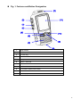
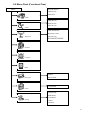
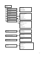
1
Model GPS-MIC-1 Combination GPS Hand-Held Tracking Receiver with Integrated Speaker Microphone for connection to any 2 Way Radio Transceiver User’s Manual V 3.3 Feb 11, 2008 ©2007-2008 Kirmuss & Associates/Infinity Gear & Technology/Infinity Advanced Technologies Patents Pending and applied for. Specifications subject to change without notice. All rights reserved. Tel: 1-888-987-9493 1-303-772-8187 1 1.0 Overview Since 2005, Infinity has been developing innovative solutions for Fire, EMS, First Responders and SAR teams worldwide. The GPS-MIC-1 is the latest technical innovation. This unit takes the features of a full function portable GPS unit and adds a speaker microphone, allowing one to use the unit as a tradition stand-alone GPS unit with the added benefit and feature of transmitting location, text messages, tracking information etc. over any two way radio. Cables are available to interface with most 2-way radios. Custom cables many be manufactured providing any 2 way transceiver with the features inherent to the GPS-MIC-1. Powered by a built-in Li Ion rechargeable battery, the GPS-MIC-1 meets the needs of today’s Professional Rescuers, EMS, Fire and Response Teams as well as Climbing Teams, Hunters, Fleet and Delivery Managers…anyone that has a need to know where staff or responders are. One may also benefit from the features found in traditional GPS units; compass, altitude, temperature, etc... THE HAND-HELD UNIT DOES NOT INCLUDE NOR OFFER VIEWING OF LOCATION USING A TOPOGRAPHICAL MAP. Other remote radio transmission solutions with GPS location and date require expensive head end equipment, expensive data transmission equipment and/or specially designed 2 way radios with GPS antenna or the installation of expensive digital radio networks, interfaces and transceivers. The Infinity GPS-MIC-1 provides users with all the accustomed features of a handheld GPS unit and adds remote connectivity over any standard 2 way radio and adding the convenience of a speaker microphone. With the appropriate adapter cable, one simply plugs the GPS-MIC-1 unit into any radio and within minutes one may send your GPS location to others that also have a GPS MIC–1 connected to their radio thereby allowing all users equipped with the device to see and locate members in one’s search team or group, sighting bearing, distance and estimated time of arrival. Users may also send text messages, all without the need of expensive or additional equipment…..this, OVER ANY ANALOG RADIO NETWORK. Consult the Factory for details regarding APCO P25 digital radio operation. The unit also operates as a traditional combination speaker microphone. At the head end, if the User is interested in having a PC based system, all that is needed is a two way radio transceiver and GPS-MIC-1 unit connected to the two way radio and then in turn via USB cable to a PC or laptop with a network connection. In this configuration, this allows incident command or this receiving station to view individual member locations, areas covered, text messaging etc... using Google Earth ™ and Google MAP ™ with the basic software package. Consult the factory for other available software for use in areas where a live LAN based or cellular modem internet connection is not available. 2 Users may record their tracks, silently provide others with information using the text messaging system, and use the device as a compass. In the latter, the user does not have to be moving. As each unit receives real time GPS locations for other units, one may select another user and use this device to plot a course to the area of the last transmission received. Whether for casual or professional use, the GPS-MIC-1 may be used to track fleets, location of users, without huge financial investment. Fleet managers may use the mic providing an affordable GPS tracking solution to school bus., livery vehicles, etc... All that is required is an appropriate cable connection to the radio transceiver. Consult the factory for details. 3 Current Product Rev 3.0 Features: • • • 2” diagonal LCD display, 120 x 160, monochrome screen, backlit Supports most brands of two way radio with optional available interface cables Built-in GPS with AMTEL chip supporting 14 simultaneous parallel GPS channels WAAS/EGNOS enabled unit with built-in antenna • • • • • • • • • • • Built in electronic compass Transceiver transmits users coordinates Tracks activity/location for a group of 5 or more people Tracks up to 50,000 waypoints Built in 512 MB solid state memory Group ID communications built-into the microphone for selective communications Built-in graphics for scenic waypoints Send and receive text messages Functions as a G Mouse and is PC supported for navigation Upgradeable firmware PC software package allows for parameter setting of the unit, GIS reading, collection of log data. • Supports export to various formats: Google Earth ™, KMZ, GPX and up to 40 other types of navigation/mapping software 2.0 Other Notes: a) The GPS-MIC-1 comes with a rechargeable lithium ion battery, USB cable and Belt Clip. b) When connected to a USB port, the USB charges the unit’s battery. c) When the GPS MIC-1 is connected to both a PC and a radio transceiver using the selected radio interface cable, this unit becomes the interface for the receiving head end. A field unit may always be used as a head end unit located at dispatch or incident command if connected to a PC or Laptop using the application software. d) Before using the equipment, charge the battery for atleast 10 hours. 4 3.0 How it works The Infinity Model GPS-MIC-1 is a computerized handheld unit that scans the open skies looking for 14 GPS satellites overhead. The unit “listens” to these orbiting satellites and eliminates the weakest satellite signals. From this point the unit computes the location of the receiver based in the relationship to the satellites being received. The unit them computes the user’s longitude and latitude which is updated every second, computing direction of travel, speed and altitude and shown on one main screen. Stored in the non volatile solid state on-board memory of the unit is the information from each update. This recording also consists of one setting waypoints, event marker points and icons, trails and routes as well as when asked, a relationship between the user and up to 5 or more other users selected in a group, and their relative distances and direction from the user’s handheld unit. By connecting a USB cable to the Infinity GPS-MIC-1 unit, one may download all the collected data to a PC, or, transmit this data over a two way transceiver (of most any type) to all other programmed group receiving radios as well as the main receiving point and a PC/or laptop if connected to a radio transceiver and another Model GPS-MIC-1 unit serving as a central controller over the air. No other interface is required. Unlike other GPS handled stand-alone units, a built in compass is built inside the unit. To ensure accuracy, this unit receives GPS satellite information as well as WAAS (Wide Area Augmentation System) boosting GPS performance increasing GPS accuracy to within 7.6 meters vertically and 2-3 meters horizontally according to the FAA. The GPS-MIC-1 receiver receives the WAAS signal that is transmitted on the GPS signal. While some remote areas do not receive WAAS signals, the GPS-MIC-1 will operate normally using the GPS receive only portion of the satellite signal. 5 4.0 WARNINGS: While a GPS receiver is a useful tool, always use another method of navigation, such a map and chart and compass. This unit will always show the navigation information with the shortest line from your current location to a selected waypoint or users location, regardless of terrain or obstructions. As a result, the system will not alert you to dangers or obstructions. User is responsible for safe navigation. 6 5.0 START UP The GPS-MIC-1 comes as pictured below: Components supplied that are part of the Kit are as follows: Belt Clip GPS Unit to USB Port Cable (for recharging of Li-Ion battery, plus data transfer) GPS-MIC-1 Unit Li-Ion Re-chargeable battery *Note: GPS to radio interface cable not included* 7 5.1 Preparing your Unit for use Insert the battery pack in the rear of the unit. To do so, 1. Open the battery cover of the handheld unit by using a coin or large flat head screwdriver; turn the screw counter clockwise to open the cover. 2. Install the battery, with the label right side up with battery connections found on the upper left had corner, mating with the pins of the GPS unit. 3. Re-install the battery compartment’s door. 4. Use the two screws supplied and attach the belt/shoulder clip to the rear case. 8 5.2 Charging Battery Pack To charge the battery, one must connect the supplied cable between the GPS-MIC-1 unit and a USB computer port and or charging adapter. To access the USB Com Port on the GPS-MIC-1 unit, open the flap on the bottom of the unit as show. Connect one end of the supplied interface cable to the base of the handheld unit (Small USB). Connect the other end of the cable to a PC or laptop computer’s USB port (Large USB). You may also plug the USB cable into either the wall charger or car charger shown in the pictures show on the next page. With the computer or power source turned on, the handheld unit will charge its battery over the USB cable. Note: Depending on the model of your computer or laptop used, you may or may not need to power the computer to charge the unit’s battery. With power on the cable, the GPS unit will indicate that the battery is charging by way of a message on the unit’s screen. 9 NOTE: Charge the battery pack first for 10 hours before using the unit. The battery will provide you with 20+ hours in standard operation. (Non power save mode). A battery level fuel gauge may be found on the unit’s LCD screen. 5.3 Turning the unit on for the first time. 1. With the battery charged, press and hold the Power Button down until the LCD shows the start up screen. (The Power Button is located on the left hand side of the unit, lower button, (Button Number 4 as depicted on the table found following these Start Up instructions.) Enter button Power Button 2. Press the center Joystick Button (Number 9 on the Table) as the [ENTER] button, once the Infinity Start Up Screen appears. 3. The Unit’s display will then show the Main Menu. 10 4. Use the center Joystick Button (Number 9 in the Table) to maneuver left, right, up and down through the various Icons to select the functions required. -Press the JOYSTICK Button (ENTER) to select the function desired. -Press the MENU/RETURN Button (Number 6) to return to the previous menu. -Press the side FUNCTION Button (Number 3) to toggle between menus and options. -When connected to a radio using an appropriate style cable, press the PTT Button (Number 2) to activate the Transmitter. Speak in a normal voice for audio operations. -Press and Hold the PTT button for at least 1 second to transmit GPS data to all other radios. 5. While in the SET UP Menu, continue setting up your system as follows: a. Set the USER NAME of the GPS-MIC-1 unit. This is the name that will be transmitted by the radio transceiver and will appear on all other field units. i. Use the Joystick to maneuver around the virtual keyboard. ii. Press the MENU key when the user name has been selected iii. Press the ENTER key to save b. Set the Time/Date i. Menu options include: 1. Time Zone (+/- GMT); 11 Time Format a. 24 hour b. 12 hour 3. Date Format a. dd/mm/yy 2. b. mm/dd/yy c. yy/mm/dd c. Set the Position Format (ddd.ddddd) Default i. Select between: 1. ddd.ddddd 2. dddmm.mmm 3. dddmmss.s d. Set the Map Datum (WGS84 Default) i. Many other options are available. e. Set the Position Format i. Metric ii. Statute f. Set the Elevation Format i. Meter ii. Feet g. Set the Temperature Format i. Celsius ii. Fahrenheit h. Set the Power Management Settings i. Backlight Time Out Timer (time that the unit’s backlight turns off) 1. Adjusted in seconds ii. Power Saving Method (turns off screen) 1. Adjusted in minutes i. Set the SOS TX Time i. Depending on your version, automatic transmit time is from 1 second to 99 minutes and 45 seconds ii. With the unit outside, the system will acquire satellite data. j. Turn GMOUSE to ON 6. STARTING THE SYSTEM a. Exit the building and when outside, access the System Settings Setup Menu, highlight SYSTEM, GPS SET and: i. Ensure that GPS POWER is set to on. ii. Perform a GPS cold start to initialize the GPS receiver under GPS 12 STARTUP. iii. Highlight the GPS Satellite Menu button. The GPS receiver will locate automatically the GPS satellites. This may take some time. You may see the signal strength and number of satellites seen by accessing the Satellite Icon on the Main Menu screen. YOU NEED TO HAVE THE UNIT SEE ATLEAST A 2D OR 3D FIX BEFORE BEING ABLE TO TRANSMITT YOUR POSITION OR A WAYPOINT. b. CALIBRATE THE COMPASS i. Access the COMPASS Menu 1. Once accessed, press and hold the ENTER Button a. A dialog box will appear and show that the compass is in Calibration Mode (Calibrating) 2. Rotate the GPS-MIC-1 unit through two 360 degree revolutions 3. Then Press the ENTER Button. a. A Message will appear if you have successfully calibrated the unit’s compass. i. If Not, repeat the process 4. Press MENU to exit. Congratulations, you have now configured your GPS hand held unit. You may now start using the system. OPERATION With the GPS-MIC-1 unit’s Power turned OFF, and with your two way transceiver also unpowered, connect the GPS-MIC-1 unit to your two way radio transceiver using the appropriate radio accessory cable. (sold separately). Consult the factory if you are not sure which cable to use. 13 Secure the GPS-MIC-1 cable to the handheld GPS unit using the two set screws provided with the cable. The connection to the GPS-MIC-1 must be flush and level. To use: First power up your two way transceiver. Then power up your GPS-MIC-1 unit. Make sure that the battery pack has been charged. You may connect the USB cable used to charge the battery to the base of the GPS-MIC-1 unit without removing the radio’s connecting cable. See picture below: Allow the unit to see the satellites before using the GPS location transmit feature built into the GPS-MIC-1. Consult the following pages as to how to maneuver through the various User Features. Pictured below: Use of the Infinity GPS-MIC-1 unit connected to an Infinity P-1000 series portable two way transceiver. 14 Pictured below: Use of a GPS-MIC-1 unit connected to a two way portable transceiver and laptop using the USB interface cable at the head end (Incident Command/Dispatch station). This cable connects the two way transceiver with the laptop or Computer via a USB cable that attaches to the GPS-MIC-1 unit which serves as the control interface. No need for a base station if you have string signal strength and good reception with a portable 2 way radio. Laptop needs to be connected to a live internet connection and Google Earth ™ using LAN, WiFi, or cellular modem. (other packages available). Commercial users need to use Google Earth Pro ™. If using a PC or laptop, consult the installation instructions for your GPS software. (SEE SECTION 11) 15 Fig. 1. Features and Button Designation (1) (11) (2) (3) (4) (5) (10) (6) (9) (7) (8) 1 GPS Antenna 2 PTT; Push To Talk 3 Function Key 4 Power On/Off button 5 Microphone 6 Return / SOS GID 7 Speaker 8 USB Port / Radio interface 9 Five Position Switch push to enter 10 Cancel / Lock 11 LCD Display 16 Button Functions Push to Talk. Pressing this button for over 0.8 seconds and PTT then releasing this button will send the geographic data location automatically over any 2 way radio transceiver. Use the PTT button for traditional radio communications. FUNC Press to cycle over function pages Press to enable backlight On/Off Press and hold to turn the unit On/Off MENU Press to return Press and hold to open SOS GID function Press to select Press and hold cycling the selection Press to enter Press and hold for two seconds to mark your current location ENTER on a track *( Add the Mark need to open Track Log function and GPS must be Fixed) CANCEL / LOCK Press to delete / information switch Press and hold to lock/unlock unit, without PTT & z & cancel SOS function: If the SOS GID function is enabled by pressing this button down and holding it for 4 seconds until “SOS ENABLED” appears on the screen, the unit will see the transceiver automatically transmit your geographic location data every 2 second to 99 minutes and 45 seconds over the air. To turn off, press and hold the SOS GID Button down for 4 seconds until SOS DISABLED appears on the LCD screen. This option serves as a “Man Down” alarm. 17 6.0 Main Menu Page (1) (2) (3) (4) (5) (6) (7) (8) (13) (14) (9) (15) (16) (11) (10) 1 (12) Battery power indication Battery power run out and unit will be automatically turn Off Full Battery 20% 2 3 4 5 6 7 8 9 10 11 12 13 14 15 16 40% 60% 80% Powered from USB Keypad lock GPS status 2D Fix 3D Fix No Fix GPS disables Data TX/RX Local time Function headline Function icon Log enable Track log mode Auto Time Range G-mouse mode Enable and NEMA data out from USB port Backlight ON Received group people Received messages Local date Temperature 18 6.2 Menu Chart (Functional Tree) MENU WATCH GROUP GROUP LIST GROUP ID Finder ADD TRACK TRACK LIST DELETE ALL Tracks ADD WAYPOINT WAYPOINT LIST Waypoint DELETE ALL WAYPOINT INBOX Satellite Compass Meter INBOX Messages WRITE NEW CALENDAR Extras USER NAME TIME/DATE CONTRAST Setting UNITS SYSTEM 19 Setting USER NAME TIME/DATE CONTRAST TIME ZONE TIME FORMAT DATE FORMAT POSITION FORMAT MAP DATUM UNITS DIST/SPEED ELEVATION SYSTEM EXIT TEMPERATURE GPS SET POWER MANAGER LANGUAGE OTHER SYSTEM INFO GPS SET POWER MANAGER GPS POWER GPS STARTUP BACKLIGHT POWER SAVE ENGLISH LANGUAGE POWERUP LOG G-MOUSE OTHER RX MUTE SOS TX TIME BAUD RATE 20 7.0 FUNCTION DETAILS 7.1 Finder Functions Select function ENTER Enter the select function page MENU Return to main page 7.1.1. WATCH GROUP (1) (4) (5) (2) (6) (7) (3) (8) 21 1 2 3 4 5 6 7 8 Grid north My location Displays selected group members direction、distance and geographic information Non-selected group member Waypoint Selected group member Real time tracking z Every 50m one point Proportional scale z proportional scale range 20m ~ 200km Proportional scale select Zoom in. Zoom out. Selection group member ENTER CANCEL MENU Into GOTO selection group member function Switch group member information Return to Finder page 22 7.1.2 GOTO GROUP MEMBERS PAGE. (2) (3) (1) 1 E.T.A. (Estimated time of arrival) 2 Line distance 3 Member location CANCEL MENU Selection information Return Finder page 23 7.1.3 Group Lists Views the list of all users programmed: communication activity log, displays the members name, geographic information, direction, and distance from the user’s position. The last received member transmission will always be listed on the top of the list, with the lowest log number as shown. (4) (1) (2) (5) (3) 1 Received number list 2 Group member SOS GID enable 3 Group member name 4 Group member direction 5 Group member distance Selection Group member N/A ENTER View Group member information CANCEL Delete Group member MENU Return to Finder page 24 7.1.4 View Group member information Next / previous Group member information MENU Return to Finder page 7.1.5 Group ID Group ID 01 ~ 99。 ENTER Confirm MENU Return to Finder page 25 7.2 Tracks Selected function ENTER Enter the select function page MENU Return 7.2.1 ADD TRACKS / STOP TRACK Select tracks LOG mode ENTER Confirm MENU Return z Log By Auto : Log automatically z Log By Time : Log by time step setting (range 1~60 sec) z Log By Range : Log by move distance setting (range 50m~500m) 26 7.2.2 TRACKS LIST 1 In user tracks Log 2 log date for a track (2) Move selection bar (1) ENTER CANCEL MENU 7.2.3 View tracks information Delete tracks Return to tracks page TRACKS INFO Select ENTER Confirm MENU Return to tracks List 7.2.4 DELETE ALL Deletes all tracks records 27 Select function 7.3 Waypoint ENTER Into the select function page MENU Return 7.3.1 ADD WAYPOINT Creating a waypoint from a current location (1) (2) (3) (4) (5) (6) 1 Waypoint icon 2 Waypoint name 3 Coordinate Location 4 Elevation 5 Waypoint number 6 Confirm 7 View the waypoint position (7) zOne may mark a new waypoint and select the icon types to be associated with this point in the field. One may also using a PC connected to the GPS-MIC-1 unit use the Infinity Workbench Software to edit a waypoint and download / upload other user defined waypoints and icons to the GPS-MIC-1 via USB cable. 28 7.3.2 Waypoint List View the waypoint list Select waypoint Delete waypoint CANCEL ENTER view waypoint information MENU Return to Waypoint page 7.2.3 Waypoint information View waypoint information including waypoint name, icon, distance, location, elevation 1 Go to waypoint 2 View waypoint 3 Send Waypoint to Group or Personal Select (1) (3) ENTER Enter the selected function MENU Return to last page (2) 29 7.2.4 GO TO Function Flag 2 3 1 1 Estimated time of arrival 2 Distance 3 Current position coordinate CANCEL Press cancel button to switch over the information bar below ENTER Press and hold into compass calibration mode MENU Return to last page Once calculated, Look and follow the flag on the top to find the Waypoint 7.2.5 DELETE ALL Deletes all waypoints. 7.2.6 WAYPOINT INBOX Shows all waypoints received by other users. (1) 1 Waypoint Received from other user 30 7.4 Satellite 7.4.1 Satellite information Æ Sky Plot FUNC ENTER MENU Location Info Æ Signal Strength Press FUNC to switch function page Press ENTER to switch between page Return to last page 31 7.5 Compass Enables compass mode FUNC Press FUNC to switch function page Press Enter button to switch two different types ENTER of compass view. Press and hold in to the calibrating mode. MENU Return to main list z Calibrating the COMPASS: Making sure that the unit is level with the ground in a horizontal position, press and hold the ENTER Button for 4 seconds to access the compass calibration mode. Rotate the unit clockwise slowly twice (2 x 360 degrees) in the same direction. Then press the ENTER Button again to see if the procedure was done correctly. If not and error message will be displayed. z Note: Please keep the unit out of any magnetic fields, near any speakers, vehicles, metal objects, metal shelters, tanks or buildings when calibrating the compass. 32 7.6 Meter This function allows one to see in Real-Time. SPEED, COURSE, TIME and GPS Coordinates. FUNC Press FUNC to switch function page MENU Return to main page 33 7.7 Message Select function ENTER Confirm. MENU Return the main page 7.7.1 Messages - In Box Views any received messages The receiving party is alerted to any messages received. Select messages. ENTER CANCEL MENU In to the messages. Delete messages Return to last page 34 7.7.2 Messages - Write New Allows you to compose, edit and send text messages FUNC Change capital or other symbol. Select text CANCEL Backspace ENTER Enter text MENU Return to Setting page Using the Joystick moving it up and down allows one to select the letter, number or character to be sent. Once a letter or character is highlighted, press the joystick button, Press the function button on the side of the radio to select Caps Lock (Capital letter mode). Press the FUNCTION button another time to release this function. Move the highlighted cursor bar in the symbol area as needed, pressing the function button to change to other symbols. 35 8.0 Settings/Setup Select function ENTER In to the selection function MENU Return to Setting page 8.1 Settings – User Name Setting your name, as seen as a group member FUNC Change capital or other symbol. select text CANCEL Backspace ENTER Enter MENU Return to Setting page Using the center Joystick button, move the highlighted curser as in the text edit mode. Press the FUNCTION key to change into the Capital lock mode. 36 Move the highlighted cursor into the symbol area, press the FUNCTION key to change and view other available symbols. 8.2 Settings – Time/Date Setting Time Zone, Time Format, Date Format. Select function ENTER MENU zTime Zone zTime Format zDate Format Enter the selection function / confirm. Return to Setting page Sets the Time zone. Sets the Unit’s Time display format:12hrs or 24hrs Military Time mode. Sets the Display format for the date: dd/mm/yy mm/dd/yy yy/mm/dd 8.3 Settings – Screen Contrast Selection contrast from 00 to 21 ENTER Confirm. MENU Return to Setting page 37 8.4 SETTINGS - Units Select function ENTER MENU z Enter the selection function / confirm. Return to Setting page POSITION MAP DATUM preferance Setting position unit ext. ddd.ddddd Allows the MAP DATUM to be changed to the users z DIST./SPEED ELEVATION Setting distance / speed unit ext. metric / mile Setting elevation unit ext. metric / feet z TEMPERATURE Setting temperature unit ext. Degree C / Degree F z z 8.5 SETTINGS- System Select function ENTER MENU z z z z GPS SET POWER MANAGER LANGUAGE OTHER Enter the selection function / confirm. Return Setting page GPS enable/disables. Select backlight timeout and auto power off timeout setting Select language (English) Other function setting 38 8.6 System Settings-Other Select function ENTER Confirm. MENU Return to Setting page z z POWER-UP LOG G-MOUSE Logs all activities since “Power On” state. GPS MOUSE mode enable/disable. z RX MUTE Silences the speaker not to hear the data stream sent over the radio transmission when the geographic data / mail sent, On/Off. z SOS TX TIME position Sets the time interval that the unit will transmit your z BAUD RATE computer Configures the Com Port speed of the USB to the 8.7 System Info Displays system information MENU Return to System page 39 z z z z z z 8.0 Power UP Temperatures Battery Waypoint Tracks Log Used Times of power-on Show the Temperatures information Battery voltage Waypoint used number Show the Track used numbers Memory capacity for tracks. Extras 8.1 .Additional Features-Calendar Select months MENU z Return to main page Calendar function, from 2000 year to 2099 year 40 9.0 System Technical Specifications Dimension 59(W) x 114(H) x 30(D)mm Weight Approx 108g (without battery and cable) LCD 120 x 160 4 level gray LCD Microphone Capacitance microphone Speaker 1W / 8ohm Power DC 3.7V / 1200mAH Li-polymer battery Battery operation time 18Hrs (backlight off) Temperature range -20C ~ +70C Compass Accuracy: ±5degrees (This need to be calibrated by user manually) Resolution : 1 degrees Thermometer -20 ~ +50 Accuracy +/- 2 degrees. 41 10.0 Notes, this page left blank 42 11.0 Software Installation 11.1 Insert the Infinity GPS-MIC-1 CD into drive bay and view the contents of the CD. Double Click the executable called “Infinity GPS-MIC-1 Software_V2.44_Setup.rar” 11.2 Follow the prompts in the Install Wizard until the software is loaded onto your computer. 11.3 Once V2.44 is installed go back to the CD and install the VCP USB Driver by double clicking on the executable called “Infinity GPS-MIC-1 VCP.exe”. During installation you will see a warning that this driver has not passed Windows Logo Testing. When you see this click “Continue Anyway”. NOTE: This window will show up twice. 11.4 Follow the steps in the Install Wizard until the driver is loaded onto your computer. This completes the installation of the USB Driver. 43 12.0 USING YOUR SYSTEM NOTE: You will need an internet connection, either a wired or wireless LAN. 12.1 Once the software has been installed, Shut down your computer and plug in the USB cable from you GPS-MIC-1. Ensure that the GPS-MIC-1 is not turned on for these steps. 12.2 When the cable is properly plugged in power up the computer while keeping the GPS-MIC-1 power off. 12.3 A window will appear once the computer is booted up saying “Welcome to the Found New Hardware Wizard”. Select “Yes, this time only” from the three options listed. Follow the directions in the install wizard using the recommended option for installation. A window will appear saying that the software does not pass the windows logo testing. Click on “Continue Anyway”. NOTE: Windows will make you do the “Found New Hardware” procedure twice in a row, you need to do this in order to see the connected GPS device. 12.4 You will now have to install Google Earth onto your computer. To do this go to http://earth.google.com/download-earth.html and download the latest version. 12.5 Open up the executable and follow the on screen directions from the Installation wizard to installing Google Earth. 44 12.6 From the Start Menu highlight All Programs, then Infinity GPS-MIC-1 Software 2.44. Right click on “Group Viewer”. From this menu highlight send to and select “Desktop (create shortcut)”. Once you have finished installing all the software onto your PC restart you computer. This step is optional but recommended. 45 13.0 Using the Infinity GPS Software 13.1 Displaying real-time locations on Google Earth 13.2 Do not turn on your GPS MIC or your two way radio. 13.2.1 With the computer turned off, connect the GPS to 2-Way Radio interface cable to the base of the GPS Mic. 13.2.2 Connect the other end of the GPS to 2-Way radio interface cable to the 2 way transceiver being used. (use the appropriate cable) 13.2.3 Connect the USB cable to the GPS MIC-1. 46 13.2.4 Plug the opposite end of the GPS MIC interface cable to the USB port of your computer. 13.4 Once the cables are connected to the radio, GPS MIC-1 unit and your PC, turn the two way radio on to the channel that you will be using. DO NOT TURN ON YOUR GPS MIC UNTIL INSTRUCTED TO DO SO. NOTE: The GPS-MIC-1mic needs to be installed in an area that allows the unit to see a GPS Satellite. Connect the PC or Laptop to a network connection. A typical installation is shown as follows (less LAN connection shown). 13.5 Start your PC or laptop computer. Keep the GPS MIC powered off until the computer is on. 13.6 When your desktop appears turn on the GPS-MIC-1. After the GPS MIC is fully powered and running, double click on the “Group Viewer” icon on your desktop. This will load up the GPS mapping application. 47 13.7 On the initial Group viewer screen locate the Com Port Box and ensure that a Com number is visible, if not ensure proper USB connection with the GPS-MIC-1 and that you have loaded the USB drivers for that device. 13.8 Below the Com Port box un-check the Auto request position box. 13.9 On the left hand side of the “Group Viewer” window you will notice a selection called KML, single click this icon. 13.10 A new window will appear within the “Group Viewer” program. In the new KML window their will be a button labeled “Browse” in the top right corner of the window. Click on this button and a new window will appear for you to select where you want your KML files to be saved and what your file name will be for your data that will be recorded for the mapping software. Once you are done naming the file click on “Save” and a new window will appear asking you if you would like to overwrite the data. Select yes. 48 13.11 Now bring the Device link window back up by clicking on the tab located on the left hand side of the application. You may now select Connect via the software application to the GPS-MIC-1, this will start streaming NMEA data to the computer. If this data is not visible recheck your GPS to Computer connection and that the USB drivers were installed properly. Depending on your previous selection the GPS information will either be recorded or not recorded. 49 Note: The remote users position will only be plotted on Google Earth if the unit has a 2D or 3D fix and if that position is recorded in the Request Positions Window. 13.12 To view the information being received on the mapping software keep the GPS-MIC-1 connected using the “Group Viewer” software and select the option called “Google Earth”. This will be located on the left hand side within the “Group Viewer” application. With this option selected you will have options on how the mapping software will be updated or when the GPS data is refreshed to show current real time movement of the other GPS units in the field. Shown on the next page are the standard default settings. 13.13 Once the options have been defined select “Launch GE”. the Google Earth application. This will open up Once Google Earth is loaded up minimize out the window and viewing the “Group Viewer” software click on “Play on GE”. This will display you GPS information on Google Earth. If you had selected for the KML Netlink settings to refresh then you will see the GPS data being continuously displayed onto Google Earth. 50 51 13.14 Once you are finished viewing the live streaming data, close the Google Earth window first and then in “Group Viewer” select the device link option and click on Disconnect. Once the unit is no longer connected you may close out the “Group Viewer” application. One may also open a stored file and show the tracks received from the various field units. 14.0 Upgrading Firmware on the GPS-MIC-1 From time to time, there may be a need to upgrade the firmware of the handheld GPS-MIC-1 unit. 14.1 With the computer turned off ensure, that your GPS-MIC-1 unit is plugged into the computer via the USB cable that was provided in the box. 14.2 Turn on your computer and once booted up and running, locate the Infinity GPS-MIC-1 Software V2.44 application on your desktop and double click it to open it. With the application open the GPS MIC if not turned on will automatically turn itself on and connect with the software. Notice a field at the bottom of the application that will say linked if operating properly. 52 14.3 Once the GPS MIC is linked you will notice the icons on the top right hand side of the program illuminate. Highlight the one that is called firmware tool and click it. The icon is the one on the furthest right. 14.4 A window will open called In Application Programmer. Click on the folder icon to the right. This will allow you to find the firmware that you downloaded onto your PC for the GPS MIC. Once selected click open and then Start. Once the firmware is uploaded press the Exit button. Allow the Infinity GPS-MIC-1 software to re-connect to the unit and power it up. Once this is done close out of the application and shut off the GPS MIC. Now you’re ready to go. In the event that the software can not re-connect to the GPS MIC, shut off the application and unplug the USB cable from the computer that is connected to the GPS MIC. Now reconnect the cable allowing the computer to auto detect it along with the software. Note: Ensure that the GPS-MIC-1 Baud rate is 9600. you will not be able to interface with the GPS-MIC-1. If this isn’t set at 9600 then 53 54