1
Nways Multiprotocol Routing Services
IBM
Protocol Configuration and Monitoring
Reference Volume 2
Version 3.2
SC30-3865-04
Nways Multiprotocol Routing Services
IBM
Protocol Configuration and Monitoring
Reference Volume 2
Version 3.2
SC30-3865-04
Note
Before using this document, read the general information under “Notices” on page xv.
Fifth Edition (November 1998)
This edition applies to Version 3.2 of the IBM Nways Multiprotocol Routing Services and to all subsequent releases
and modifications until otherwise indicated in new editions or technical newsletters.
Order publications through your IBM representative or the IBM branch office serving your locality. Publications are
not stocked at the address below.
IBM welcomes your comments. A form for readers' comments is provided at the back of this publication. If the form
has been removed, you may address your comments to:
Department CGF
Design & Information Development
IBM Corporation
P.O. Box 12195
RESEARCH TRIANGLE PARK NC 27709
USA
When you send information to IBM, you grant IBM a nonexclusive right to use or distribute the information in any
way it believes appropriate without incurring any obligation to you.
© Copyright International Business Machines Corporation 1994, 1998. All rights reserved.
Note to U.S. Government Users — Documentation related to restricted rights — Use, duplication or disclosure is
subject to restrictions set forth in GSA ADP Schedule Contract with IBM Corp.
Contents
Figures . . . . . . . . . . . . . . . . . . . . . . . . . . .
Tables
xi
. . . . . . . . . . . . . . . . . . . . . . . . . . . xiii
Notices . . . . . . . . . . . . . . . . . . . . . . . . . . .
xv
Notice to Users of Online Versions of This Book . . . . . . . . . . . xvii
Trademarks
. . . . . . . . . . . . . . . . . . . . . . . . . xix
xxi
About the Software . . . . . . . . . . . . . . . . . . . . . . . xxi
Conventions Used in This Manual . . . . . . . . . . . . . . . . . xxii
IBM 2210 Nways Multiprotocol Router Publications . . . . . . . . . . . xxii
Summary of Changes for the IBM 2210 Software Library . . . . . . . . . xxiv
Editorial Changes . . . . . . . . . . . . . . . . . . . . . . xxvi
Getting Help . . . . . . . . . . . . . . . . . . . . . . . . . xxvi
Exiting a Lower Level Environment . . . . . . . . . . . . . . . . . xxvii
Chapter 1. APPN . . . . . . . . . . . . . . . . . . . . .
What is APPN? . . . . . . . . . . . . . . . . . . . . . .
Peer-to-Peer Communications . . . . . . . . . . . . . . . .
APPN Node Types . . . . . . . . . . . . . . . . . . . .
What APPN Functions Are Implemented on the Router? . . . . . .
APPN Network Node Optional Features . . . . . . . . . . . . .
High-Performance Routing . . . . . . . . . . . . . . . . .
Dependent LU Requester (DLUR) . . . . . . . . . . . . . .
APPN Connection Network . . . . . . . . . . . . . . . . .
Branch Extender . . . . . . . . . . . . . . . . . . . . .
Extended Border Nodes . . . . . . . . . . . . . . . . . .
Branch Extender vs. Extended Border Node . . . . . . . . . . .
Managing a Network Node . . . . . . . . . . . . . . . . .
Entry Point Capabilities for APPN-related Alerts . . . . . . . . .
SNMP Capabilities for APPN MIBs . . . . . . . . . . . . . .
Topology Database Garbage Collection . . . . . . . . . . . .
Configurable Held Alert Queue . . . . . . . . . . . . . . . .
Implicit Focal Point . . . . . . . . . . . . . . . . . . . .
Dynamic Definition of Dependent LUs (DDDLU) . . . . . . . . .
TN3270E Server . . . . . . . . . . . . . . . . . . . . .
Support for Subarea SNA Connections from the TN3270E Server to the
Enterprise Extender Support for HPR over IP . . . . . . . . . .
Supported DLCs . . . . . . . . . . . . . . . . . . . . . .
Router Configuration Process . . . . . . . . . . . . . . . . .
Configuration Changes That Require the APPN Function to Restart . .
Configuration Requirements for APPN . . . . . . . . . . . . .
Configuring the Router as an APPN Network Node . . . . . . . .
Configuring Branch Extender . . . . . . . . . . . . . . . .
Configuring Extended Border Nodes. . . . . . . . . . . . . .
High-Performance Routing . . . . . . . . . . . . . . . . .
DLUR . . . . . . . . . . . . . . . . . . . . . . . . .
Configuring Focal Points . . . . . . . . . . . . . . . . . .
Configuring Held Alert Queue Size . . . . . . . . . . . . . .
Defining Transmission Group (TG) Characteristics . . . . . . . .
Calculating APPN Routes Using TG Characteristics . . . . . . . .
© Copyright IBM Corp. 1994, 1998
. .
. .
. .
. .
. .
. .
. .
. .
. .
. .
. .
. .
. .
. .
. .
. .
. .
. .
. .
. .
Host
. .
. .
. .
. .
. .
. .
. .
. .
. .
. .
. .
. .
. .
. .
1
1
1
1
3
6
6
9
12
13
14
16
17
17
19
19
19
19
20
20
23
25
25
25
26
26
26
30
31
36
36
36
36
36
37
iii
iv
COS Options . . . . . . . . . . . . . . . . . .
APPN Node Tuning . . . . . . . . . . . . . . . .
Node Service (Traces) . . . . . . . . . . . . . . .
APPN Trace Enhancements. . . . . . . . . . . . .
Accounting and Node Statistics . . . . . . . . . . .
DLUR Retry Algorithm . . . . . . . . . . . . . . .
APPN Implementation on the Router Using DLSw . . . .
APPN Frame Relay BAN Connection Network Implementation
Port Level Parameter Lists . . . . . . . . . . . . .
Link Level Parameter Lists . . . . . . . . . . . . .
LU Parameter List . . . . . . . . . . . . . . . .
Node Level Parameter Lists . . . . . . . . . . . . .
APPN Configuration Notes . . . . . . . . . . . . . .
Configuring a Permanent Circuit Using ISDN . . . . . .
Configuring APPN Over Dial on Demand Circuits . . . . .
Configuring WAN Reroute . . . . . . . . . . . . .
Configuring WAN Restoral . . . . . . . . . . . . .
Configuring V.25bis . . . . . . . . . . . . . . . .
Configuring V.34 . . . . . . . . . . . . . . . . .
Configuring APPN Over ATM . . . . . . . . . . . .
Configuring APPN Using SDLC . . . . . . . . . . .
Configuring APPN Over X.25 . . . . . . . . . . . .
Configuring APPN Over Frame Relay . . . . . . . . .
Configuring APPN Over Frame Relay BAN . . . . . . .
Configuring TN3270E Using DLUR . . . . . . . . . .
Configuring TN3270E Using a Subarea Connection . . . .
Configuring Enterprise Extender Support for HPR Over IP .
Configuring Connection Networks over HPR over IP . . . .
Configuring an Extended Border Node . . . . . . . . .
.
.
.
.
.
.
.
.
.
.
.
.
.
.
.
.
.
.
.
.
.
.
.
.
.
.
.
.
.
.
.
.
.
.
.
.
.
.
.
.
.
.
.
.
.
.
.
.
.
.
.
.
.
.
.
.
.
.
.
.
.
.
.
.
.
.
.
.
.
.
.
.
.
.
.
.
.
.
.
.
.
.
.
.
.
.
.
.
.
.
.
.
.
.
.
.
.
.
.
.
.
.
.
.
.
.
.
.
.
.
.
.
.
.
.
.
.
.
.
.
.
.
.
.
.
.
.
.
.
.
.
.
.
.
.
.
.
.
.
.
.
.
.
.
.
.
.
.
.
.
.
.
.
.
.
.
.
.
.
.
.
.
.
.
.
.
.
.
.
.
.
.
.
.
38
38
39
40
40
41
43
44
48
48
48
48
49
49
51
54
59
60
62
63
65
70
73
74
75
77
79
80
80
Chapter 2. Configuring and Monitoring APPN
Accessing the APPN Configuration Process . .
APPN Configuration Command Summary. . .
APPN Configuration Command Detail . . . .
Enable/Disable . . . . . . . . . . .
Set . . . . . . . . . . . . . . . .
Add. . . . . . . . . . . . . . . .
Delete . . . . . . . . . . . . . . .
List . . . . . . . . . . . . . . . .
Activate_new_config . . . . . . . . .
TN3270E . . . . . . . . . . . . .
Monitoring APPN . . . . . . . . . . . .
Accessing the APPN Monitoring Commands . .
APPN Monitoring Commands . . . . . . .
Aping . . . . . . . . . . . . . . .
Dump . . . . . . . . . . . . . . .
List . . . . . . . . . . . . . . . .
Memory . . . . . . . . . . . . . .
Restart . . . . . . . . . . . . . .
Stop . . . . . . . . . . . . . . .
TN3270E . . . . . . . . . . . . .
.
.
.
.
.
.
.
.
.
.
.
.
.
.
.
.
.
.
.
.
.
.
.
.
.
.
.
.
.
.
.
.
.
.
.
.
.
.
.
.
.
.
.
.
.
.
.
.
.
.
.
.
.
.
.
.
.
.
.
.
.
.
.
.
.
.
.
.
.
.
.
.
.
.
.
.
.
.
.
.
.
.
.
.
.
.
.
.
.
.
.
.
.
.
.
.
.
.
.
.
.
.
.
.
.
.
.
.
.
.
.
.
.
.
.
.
.
.
.
.
.
.
.
.
.
.
.
.
.
.
.
.
.
.
.
.
.
.
.
.
.
.
.
.
.
.
.
.
.
.
.
.
.
.
.
.
.
.
.
.
.
.
.
.
.
.
.
.
.
.
.
.
.
.
.
.
.
.
.
.
.
.
.
.
.
.
.
.
.
.
.
.
.
.
.
.
.
.
.
.
.
.
.
.
.
.
.
.
.
.
.
.
.
.
.
.
.
.
.
.
.
.
.
.
.
.
.
.
.
.
.
.
.
.
.
.
.
.
.
.
.
.
.
.
.
.
.
.
.
.
.
.
81
81
81
83
83
83
124
192
193
193
194
208
208
209
209
210
210
211
211
211
211
Chapter 3. Using AppleTalk Phase 2 .
Basic Configuration Procedures . . .
Enabling Router Parameters . . .
Setting Network Parameters. . . .
.
.
.
.
.
.
.
.
.
.
.
.
.
.
.
.
.
.
.
.
.
.
.
.
.
.
.
.
.
.
.
.
.
.
.
.
.
.
.
.
.
.
.
.
.
.
.
.
213
213
213
213
MRS V3.2 Protocol Config Ref Vol 2
.
.
.
.
.
.
.
.
.
.
.
.
AppleTalk over PPP. . . . . . .
AppleTalk 2 Zone Filters . . . . .
General Information . . . . . .
Why ZoneName Filters? . . . .
How Do You Add Filters? . . . .
Sample Configuration Procedures
.
.
.
.
.
.
.
.
.
.
.
.
.
.
.
.
.
.
.
.
.
.
.
.
.
.
.
.
.
.
.
.
.
.
.
.
.
.
.
.
.
.
.
.
.
.
.
.
.
.
.
.
.
.
.
.
.
.
.
.
.
.
.
.
.
.
.
.
.
.
.
.
214
214
214
215
215
216
Chapter 4. Configuring and Monitoring AppleTalk Phase 2
Accessing the AppleTalk Phase 2 Configuration Environment
AppleTalk Phase 2 Configuration Commands . . . . . .
Add. . . . . . . . . . . . . . . . . . . . .
Delete . . . . . . . . . . . . . . . . . . . .
Disable . . . . . . . . . . . . . . . . . . .
Enable . . . . . . . . . . . . . . . . . . .
List . . . . . . . . . . . . . . . . . . . . .
Set . . . . . . . . . . . . . . . . . . . . .
Accessing the AppleTalk Phase 2 Monitoring Environment .
AppleTalk Phase 2 Monitoring Commands . . . . . . .
Atecho . . . . . . . . . . . . . . . . . . .
Cache . . . . . . . . . . . . . . . . . . . .
Clear Counters . . . . . . . . . . . . . . . .
Counters . . . . . . . . . . . . . . . . . . .
Dump . . . . . . . . . . . . . . . . . . . .
Interface . . . . . . . . . . . . . . . . . . .
.
.
.
.
.
.
.
.
.
.
.
.
.
.
.
.
.
.
.
.
.
.
.
.
.
.
.
.
.
.
.
.
.
.
.
.
.
.
.
.
.
.
.
.
.
.
.
.
.
.
.
.
.
.
.
.
.
.
.
.
.
.
.
.
.
.
.
.
.
.
.
.
.
.
.
.
.
.
.
.
.
.
.
.
.
.
.
.
.
.
.
.
.
.
.
.
.
.
.
.
.
.
.
.
.
.
.
.
.
.
.
.
.
.
.
.
.
.
.
221
221
221
222
223
224
225
226
227
229
229
229
230
231
231
231
232
Chapter 5. Using VINES. . . . . . . . . . .
VINES Overview . . . . . . . . . . . . . .
VINES Over Router Protocols and Interfaces . .
Service and Client Nodes . . . . . . . . .
VINES Network Layer Protocols . . . . . . . .
VINES Internet Protocol (VINES IP) . . . . . .
Routing Update Protocol (RTP) . . . . . . .
Internet Control Protocol (ICP) . . . . . . . .
VINES Address Resolution Protocol (VINES ARP)
Basic Configuration Procedures . . . . . . . .
Running Banyan VINES on the Bridging Router .
Running Banyan VINES over WAN Links . . . .
.
.
.
.
.
.
.
.
.
.
.
.
.
.
.
.
.
.
.
.
.
.
.
.
.
.
.
.
.
.
.
.
.
.
.
.
.
.
.
.
.
.
.
.
.
.
.
.
.
.
.
.
.
.
.
.
.
.
.
.
.
.
.
.
.
.
.
.
.
.
.
.
.
.
.
.
.
.
.
.
.
.
.
.
.
.
.
.
.
.
.
.
.
.
.
.
.
.
.
.
.
.
.
.
.
.
.
.
.
.
.
.
.
.
.
.
.
.
.
.
233
233
233
233
234
234
235
238
238
239
239
240
Chapter 6. Configuring and Monitoring VINES
Accessing the VINES Configuration Environment
VINES Configuration Commands . . . . . .
Add. . . . . . . . . . . . . . . .
Delete . . . . . . . . . . . . . . .
Disable . . . . . . . . . . . . . .
Enable . . . . . . . . . . . . . .
List . . . . . . . . . . . . . . . .
Set . . . . . . . . . . . . . . . .
Accessing the VINES Monitoring Environment .
VINES Monitoring Commands . . . . . . .
Counters . . . . . . . . . . . . . .
Dump . . . . . . . . . . . . . . .
Route . . . . . . . . . . . . . . .
.
.
.
.
.
.
.
.
.
.
.
.
.
.
.
.
.
.
.
.
.
.
.
.
.
.
.
.
.
.
.
.
.
.
.
.
.
.
.
.
.
.
.
.
.
.
.
.
.
.
.
.
.
.
.
.
.
.
.
.
.
.
.
.
.
.
.
.
.
.
.
.
.
.
.
.
.
.
.
.
.
.
.
.
.
.
.
.
.
.
.
.
.
.
.
.
.
.
.
.
.
.
.
.
.
.
.
.
.
.
.
.
.
.
.
.
.
.
.
.
.
.
.
.
.
.
.
.
.
.
.
.
.
.
.
.
.
.
.
.
241
241
241
241
242
242
242
243
244
245
245
245
246
248
.
.
.
.
.
.
.
.
.
.
.
.
.
.
.
.
.
.
.
.
.
.
.
.
.
.
.
.
.
.
.
.
.
.
.
.
.
.
.
.
.
.
.
.
.
.
.
.
.
.
.
.
Chapter 7. Using DNA IV . . . . . . . . . . . . . . . . . . . . 249
DNA IV Overview . . . . . . . . . . . . . . . . . . . . . . . 249
DNA IV Terminology and Concepts . . . . . . . . . . . . . . . . 250
Contents
v
Routing . . . . . . . . . . . . .
Routing Tables . . . . . . . . . .
Area Routers . . . . . . . . . . .
Configuring Routing Parameters . . . .
IBM’s Implementation of DNA IV . . . . .
Managing Traffic Using Access Control. .
Managing Traffic Using Area Routing Filters
Configuring DNA IV . . . . . . . . .
vi
.
.
.
.
.
.
.
.
.
.
.
.
.
.
.
.
.
.
.
.
.
.
.
.
.
.
.
.
.
.
.
.
.
.
.
.
.
.
.
.
.
.
.
.
.
.
.
.
.
.
.
.
.
.
.
.
.
.
.
.
.
.
.
.
.
.
.
.
.
.
.
.
.
.
.
.
.
.
.
.
.
.
.
.
.
.
.
.
.
.
.
.
.
.
.
.
251
251
252
252
252
253
256
261
Chapter 8. Configuring and Monitoring DNA IV
DNA IV Configuration and Monitoring Commands .
Define/Set . . . . . . . . . . . . . .
Purge . . . . . . . . . . . . . . . .
Set . . . . . . . . . . . . . . . . .
Show . . . . . . . . . . . . . . . .
Show/List . . . . . . . . . . . . . .
Zero . . . . . . . . . . . . . . . .
.
.
.
.
.
.
.
.
.
.
.
.
.
.
.
.
.
.
.
.
.
.
.
.
.
.
.
.
.
.
.
.
.
.
.
.
.
.
.
.
.
.
.
.
.
.
.
.
.
.
.
.
.
.
.
.
.
.
.
.
.
.
.
.
.
.
.
.
.
.
.
.
.
.
.
.
.
.
.
.
.
.
.
.
.
.
.
.
265
265
266
274
274
274
277
283
Chapter 9. Using OSI/DECnet V. . . . . . . . . .
OSI Overview . . . . . . . . . . . . . . . . .
NSAP Addressing . . . . . . . . . . . . . . .
IDP . . . . . . . . . . . . . . . . . . . .
DSP . . . . . . . . . . . . . . . . . . .
IS-IS Addressing Format . . . . . . . . . . . .
GOSIP Version 2 NSAPs . . . . . . . . . . . .
Multicast Addresses. . . . . . . . . . . . . . .
OSI Routing . . . . . . . . . . . . . . . . .
IS-IS Protocol . . . . . . . . . . . . . . . . .
IS-IS Areas . . . . . . . . . . . . . . . . .
IS-IS Domain . . . . . . . . . . . . . . . .
IS to IS Hello (IIH) Message . . . . . . . . . .
L1 IIH Message . . . . . . . . . . . . . . .
L2 IIH Message . . . . . . . . . . . . . . .
Point-to-Point IIH Message . . . . . . . . . . .
Designated IS . . . . . . . . . . . . . . . .
Link State Databases . . . . . . . . . . . . .
Routing Tables . . . . . . . . . . . . . . .
Address Prefix Encoding . . . . . . . . . . . .
Authentication Passwords . . . . . . . . . . .
ESIS Protocol . . . . . . . . . . . . . . . . .
Hello Message . . . . . . . . . . . . . . .
End System Hello (ESH) Message . . . . . . . .
Intermediate System Hello (ISH) Messages . . . . .
X.25 Circuits for DECnet V/OSI . . . . . . . . . .
Routing Circuits . . . . . . . . . . . . . . .
Filters . . . . . . . . . . . . . . . . . . .
Templates . . . . . . . . . . . . . . . . .
Link Initialization . . . . . . . . . . . . . . .
OSI/DECnet V Configuration . . . . . . . . . . .
Basic Configuration Procedure . . . . . . . . . .
Configuring OSI Over an Ethernet or a Token-Ring LAN
Configuring OSI Over X.25 or Frame Relay . . . . .
Configuring a DNA V Router for a DNA IV Environment
DNA IV and DNA V Algorithm Considerations . . . .
.
.
.
.
.
.
.
.
.
.
.
.
.
.
.
.
.
.
.
.
.
.
.
.
.
.
.
.
.
.
.
.
.
.
.
.
.
.
.
.
.
.
.
.
.
.
.
.
.
.
.
.
.
.
.
.
.
.
.
.
.
.
.
.
.
.
.
.
.
.
.
.
.
.
.
.
.
.
.
.
.
.
.
.
.
.
.
.
.
.
.
.
.
.
.
.
.
.
.
.
.
.
.
.
.
.
.
.
.
.
.
.
.
.
.
.
.
.
.
.
.
.
.
.
.
.
.
.
.
.
.
.
.
.
.
.
.
.
.
.
.
.
.
.
.
.
.
.
.
.
.
.
.
.
.
.
.
.
.
.
.
.
.
.
.
.
.
.
.
.
.
.
.
.
.
.
.
.
.
.
.
.
.
.
.
.
.
.
.
.
.
.
.
.
.
.
.
.
.
.
.
.
.
.
.
.
.
.
.
.
.
.
.
.
.
.
.
.
.
.
.
.
.
.
.
.
.
.
.
.
.
.
.
.
.
.
.
.
.
.
.
.
.
.
.
.
.
.
.
.
.
.
.
.
.
.
.
.
.
.
.
.
.
.
.
.
.
.
.
.
.
.
.
.
.
.
.
.
.
.
.
.
.
.
.
.
.
.
285
285
286
286
287
287
288
288
289
289
289
290
292
292
293
293
293
294
295
297
298
299
299
299
299
299
300
300
301
301
301
301
302
302
302
303
Chapter 10. Configuring and Monitoring OSI/DECnet V
. . . . . . . . 305
MRS V3.2 Protocol Config Ref Vol 2
.
.
.
.
.
.
.
.
Accessing the OSI Configuration Environment . . .
DECnet V/OSI Configuration Commands . . . . .
Add. . . . . . . . . . . . . . . . . .
Change . . . . . . . . . . . . . . . .
Clear . . . . . . . . . . . . . . . . .
Delete . . . . . . . . . . . . . . . . .
Disable . . . . . . . . . . . . . . . .
Enable . . . . . . . . . . . . . . . .
List . . . . . . . . . . . . . . . . . .
Set . . . . . . . . . . . . . . . . . .
Accessing the OSI/DECnet V Monitoring Environment
OSI/DECnet V Monitoring Commands . . . . . .
Addresses . . . . . . . . . . . . . . .
Change Metric. . . . . . . . . . . . . .
CLNP-Stats . . . . . . . . . . . . . . .
Designated-router . . . . . . . . . . . .
DNAV-info . . . . . . . . . . . . . . .
ES-Adjacencies . . . . . . . . . . . . .
ES-IS-Stats . . . . . . . . . . . . . . .
IS-Adjacencies . . . . . . . . . . . . .
IS-IS-Stats . . . . . . . . . . . . . . .
L1-Routes . . . . . . . . . . . . . . .
L2-Routes . . . . . . . . . . . . . . .
L1-Summary . . . . . . . . . . . . . .
L2-Summary . . . . . . . . . . . . . .
L1-Update . . . . . . . . . . . . . . .
L2-Update . . . . . . . . . . . . . . .
Ping-1139 . . . . . . . . . . . . . . .
Route . . . . . . . . . . . . . . . . .
Send (Echo Packet). . . . . . . . . . . .
Subnets . . . . . . . . . . . . . . . .
Toggle (Alias/No Alias) . . . . . . . . . . .
Traceroute . . . . . . . . . . . . . . .
.
.
.
.
.
.
.
.
.
.
.
.
.
.
.
.
.
.
.
.
.
.
.
.
.
.
.
.
.
.
.
.
.
.
.
.
.
.
.
.
.
.
.
.
.
.
.
.
.
.
.
.
.
.
.
.
.
.
.
.
.
.
.
.
.
.
.
.
.
.
.
.
.
.
.
.
.
.
.
.
.
.
.
.
.
.
.
.
.
.
.
.
.
.
.
.
.
.
.
.
.
.
.
.
.
.
.
.
.
.
.
.
.
.
.
.
.
.
.
.
.
.
.
.
.
.
.
.
.
.
.
.
.
.
.
.
.
.
.
.
.
.
.
.
.
.
.
.
.
.
.
.
.
.
.
.
.
.
.
.
.
.
.
.
.
.
.
.
.
.
.
.
.
.
.
.
.
.
.
.
.
.
.
.
.
.
.
.
.
.
.
.
.
.
.
.
.
.
.
.
.
.
.
.
.
.
.
.
.
.
.
.
.
.
.
.
.
.
.
.
.
.
.
.
.
.
.
.
.
.
.
.
.
.
.
.
.
.
.
.
.
.
.
.
.
.
.
.
.
.
.
.
.
.
.
.
.
.
.
.
.
.
.
.
.
.
.
.
.
.
.
.
.
.
.
.
.
.
.
.
.
.
.
.
.
.
.
.
.
.
.
.
.
.
.
.
.
.
.
.
.
.
.
.
.
.
.
.
.
.
.
.
.
.
.
.
.
.
.
.
.
.
.
.
.
.
.
.
.
.
305
305
305
311
313
314
316
317
317
323
329
329
330
331
331
333
333
334
334
336
336
338
338
339
340
340
341
341
342
342
343
343
343
Chapter 11. Using NHRP . . . . . . . . .
Next Hop Resolution Protocol (NHRP) Overview .
Benefits of NHRP and the IBM implementation .
Performance Characteristics . . . . . . .
Examples of NHRP Configurations . . . . .
NHRP Implementation . . . . . . . . . .
Configuration Parameters . . . . . . . .
.
.
.
.
.
.
.
.
.
.
.
.
.
.
.
.
.
.
.
.
.
.
.
.
.
.
.
.
.
.
.
.
.
.
.
.
.
.
.
.
.
.
.
.
.
.
.
.
.
.
.
.
.
.
.
.
.
.
.
.
.
.
.
.
.
.
.
.
.
.
.
.
.
.
.
.
.
345
345
346
347
347
352
353
Chapter 12. Configuring and Monitoring NHRP.
Accessing the NHRP Configuration Process . . .
NHRP Configuration Commands . . . . . . .
Enable NHRP . . . . . . . . . . . . .
Disable NHRP . . . . . . . . . . . . .
Advanced Config . . . . . . . . . . . .
List . . . . . . . . . . . . . . . . .
NHRP Advanced Configuration Commands . . .
Add. . . . . . . . . . . . . . . . .
Delete . . . . . . . . . . . . . . . .
Change . . . . . . . . . . . . . . .
List . . . . . . . . . . . . . . . . .
Set . . . . . . . . . . . . . . . . .
Accessing the NHRP Monitoring Process . . . .
.
.
.
.
.
.
.
.
.
.
.
.
.
.
.
.
.
.
.
.
.
.
.
.
.
.
.
.
.
.
.
.
.
.
.
.
.
.
.
.
.
.
.
.
.
.
.
.
.
.
.
.
.
.
.
.
.
.
.
.
.
.
.
.
.
.
.
.
.
.
.
.
.
.
.
.
.
.
.
.
.
.
.
.
.
.
.
.
.
.
.
.
.
.
.
.
.
.
.
.
.
.
.
.
.
.
.
.
.
.
.
.
.
.
.
.
.
.
.
.
.
.
.
.
.
.
.
.
.
.
.
.
.
.
.
.
.
.
.
.
.
.
.
.
.
.
.
.
.
.
.
.
.
.
359
359
359
359
360
360
360
361
361
362
363
364
365
368
Contents
vii
NHRP Monitoring Commands
Box Status . . . . . .
Interface Status . . . .
Statistics . . . . . . .
Cache . . . . . . . .
Server_purge_cache . .
MIB. . . . . . . . .
LANE Shortcuts . . . .
CONFIG Parameters . .
Reset . . . . . . . .
NHRP Packet Tracing . . .
.
.
.
.
.
.
.
.
.
.
.
.
.
.
.
.
.
.
.
.
.
.
.
.
.
.
.
.
.
.
.
.
.
.
.
.
.
.
.
.
.
.
.
.
.
.
.
.
.
.
.
.
.
.
.
.
.
.
.
.
.
.
.
.
.
.
.
.
.
.
.
.
.
.
.
.
.
.
.
.
.
.
.
.
.
.
.
.
.
.
.
.
.
.
.
.
.
.
.
.
.
.
.
.
.
.
.
.
.
.
.
.
.
.
.
.
.
.
.
.
.
.
.
.
.
.
.
.
.
.
.
.
.
.
.
.
.
.
.
.
.
.
.
.
.
.
.
.
.
.
.
.
.
.
.
.
.
.
.
.
.
.
.
.
.
.
.
.
.
.
.
.
.
.
.
.
.
.
.
.
.
.
.
.
.
.
.
.
.
.
.
.
.
.
.
.
.
.
.
.
.
.
.
.
.
.
.
.
.
369
369
369
369
370
371
371
372
373
374
374
.
.
.
.
.
.
.
.
.
.
.
.
.
.
.
.
.
.
.
.
.
.
.
.
.
.
.
.
.
.
.
.
.
.
.
.
.
.
.
.
.
.
.
.
.
.
.
.
.
.
.
.
.
.
.
.
.
.
.
.
.
.
.
.
.
.
.
.
.
.
.
.
.
.
.
.
.
.
.
.
.
.
.
.
.
.
.
.
.
.
.
.
.
.
.
.
.
.
.
.
.
.
.
.
.
.
.
.
.
.
.
.
.
.
.
.
.
.
.
.
.
.
.
.
.
.
.
.
.
.
.
.
.
.
.
.
.
.
.
.
.
.
.
.
.
.
.
.
.
.
.
.
.
.
.
.
.
.
.
.
.
.
.
.
.
.
.
.
.
.
.
.
.
.
.
.
.
.
.
.
.
.
.
.
.
.
.
.
.
.
.
.
.
.
.
.
.
.
.
.
.
.
.
.
.
.
.
.
.
.
.
.
.
.
.
.
.
.
.
.
.
.
.
.
.
.
.
.
.
.
.
.
.
.
.
.
.
.
.
.
.
.
.
.
.
.
.
.
.
.
.
.
377
377
377
377
378
378
378
379
379
379
380
380
380
380
380
381
381
381
Chapter 14. Configuring and Monitoring IPV6
Accessing the IPV6 Configuration Environment.
IPV6 Configuration Commands . . . . . .
Add. . . . . . . . . . . . . . . .
Change . . . . . . . . . . . . . .
Delete . . . . . . . . . . . . . . .
Disable . . . . . . . . . . . . . .
Enable . . . . . . . . . . . . . .
List . . . . . . . . . . . . . . . .
Set . . . . . . . . . . . . . . . .
Update . . . . . . . . . . . . . .
Update Packet-filter Commands . . . . .
Accessing the IPV6 Monitoring Environment . .
IPV6 Monitoring Commands. . . . . . . .
Cache . . . . . . . . . . . . . . .
Counters . . . . . . . . . . . . . .
Dump routing tables . . . . . . . . .
Interface addresses . . . . . . . . . .
Mcast . . . . . . . . . . . . . . .
Mld . . . . . . . . . . . . . . . .
Route . . . . . . . . . . . . . . .
Sizes . . . . . . . . . . . . . . .
Static routes . . . . . . . . . . . .
Packet-filter . . . . . . . . . . . . .
Path-mtu . . . . . . . . . . . . . .
.
.
.
.
.
.
.
.
.
.
.
.
.
.
.
.
.
.
.
.
.
.
.
.
.
.
.
.
.
.
.
.
.
.
.
.
.
.
.
.
.
.
.
.
.
.
.
.
.
.
.
.
.
.
.
.
.
.
.
.
.
.
.
.
.
.
.
.
.
.
.
.
.
.
.
.
.
.
.
.
.
.
.
.
.
.
.
.
.
.
.
.
.
.
.
.
.
.
.
.
.
.
.
.
.
.
.
.
.
.
.
.
.
.
.
.
.
.
.
.
.
.
.
.
.
.
.
.
.
.
.
.
.
.
.
.
.
.
.
.
.
.
.
.
.
.
.
.
.
.
.
.
.
.
.
.
.
.
.
.
.
.
.
.
.
.
.
.
.
.
.
.
.
.
.
.
.
.
.
.
.
.
.
.
.
.
.
.
.
.
.
.
.
.
.
.
.
.
.
.
.
.
.
.
.
.
.
.
.
.
.
.
.
.
.
.
.
.
.
.
.
.
.
.
.
.
.
.
.
.
.
.
.
.
.
.
.
.
.
.
.
.
.
.
.
.
.
.
.
.
.
.
.
.
.
.
.
.
.
.
.
.
.
.
.
.
.
.
.
.
.
.
.
.
.
.
.
.
.
.
.
.
.
.
.
.
.
.
.
.
.
.
.
.
.
.
.
.
.
.
383
383
383
383
387
387
388
388
389
391
394
394
397
398
398
398
399
399
399
400
400
400
401
401
401
Chapter 13. Using IP Version 6 (IPv6) .
IPv6 Overview . . . . . . . . . . .
IPv6 Comparison with IPv4 . . . . . .
IPv6 Addressing . . . . . . . . . .
IPv6 Address Format . . . . . . .
Text Representation of Address Prefixes
IPv6 Header Format . . . . . . . .
IPv6 Minimum MTU . . . . . . . . .
IPv6 Mandatory Path MTU Discovery . .
IPv6 Mandatory Security . . . . . . .
IPv6 Neighbor Discovery Protocol (NDP) .
Router and Prefix Discovery. . . . .
Address Autoconfiguration . . . . .
Address Resolution . . . . . . . .
Neighbor Unreachability Detection . .
Redirect . . . . . . . . . . . .
IPv6 over IPv4 Tunneling . . . . . . .
Protocol Independent Multicast (PIM) . .
viii
MRS V3.2 Protocol Config Ref Vol 2
Ping6 . . . . . . . . . . . . . . . . . . . . . . . . . . . 402
Traceroute6. . . . . . . . . . . . . . . . . . . . . . . . . 402
Tunnels . . . . . . . . . . . . . . . . . . . . . . . . . . 403
Chapter 15. Configuring and Monitoring Neighbor
(NDP) . . . . . . . . . . . . . . . . .
Accessing the NDP Configuration Environment. . .
NDP Configuration Commands. . . . . . . . .
Add. . . . . . . . . . . . . . . . . .
Change . . . . . . . . . . . . . . . .
Delete . . . . . . . . . . . . . . . . .
Disable . . . . . . . . . . . . . . . .
Enable . . . . . . . . . . . . . . . .
List . . . . . . . . . . . . . . . . . .
Accessing the NDP Monitoring Environment . . . .
NDP Monitoring Commands. . . . . . . . . .
Dump . . . . . . . . . . . . . . . . .
Ping6 . . . . . . . . . . . . . . . . .
List . . . . . . . . . . . . . . . . . .
Discovery
. . . .
. . . .
. . . .
. . . .
. . . .
. . . .
. . . .
. . . .
. . . .
. . . .
. . . .
. . . .
. . . .
. . . .
Protocol
. . . .
. . . .
. . . .
. . . .
. . . .
. . . .
. . . .
. . . .
. . . .
. . . .
. . . .
. . . .
. . . .
. . . .
Chapter 16. Configuring and Monitoring Protocol Independent
Routing Protocol (PIM) . . . . . . . . . . . . . . .
Accessing the PIM Configuration Environment . . . . . . . .
PIM Configuration Commands . . . . . . . . . . . . . .
Delete . . . . . . . . . . . . . . . . . . . . . .
Disable . . . . . . . . . . . . . . . . . . . . .
Enable . . . . . . . . . . . . . . . . . . . . .
List . . . . . . . . . . . . . . . . . . . . . . .
Set . . . . . . . . . . . . . . . . . . . . . . .
Accessing the PIM Monitoring Environment . . . . . . . . .
PIM Monitoring Commands . . . . . . . . . . . . . . .
Dump routing tables . . . . . . . . . . . . . . . .
Clear . . . . . . . . . . . . . . . . . . . . . .
Interface . . . . . . . . . . . . . . . . . . . . .
Join . . . . . . . . . . . . . . . . . . . . . .
Leave . . . . . . . . . . . . . . . . . . . . . .
Mcache . . . . . . . . . . . . . . . . . . . . .
Mgroup . . . . . . . . . . . . . . . . . . . . .
Mstats. . . . . . . . . . . . . . . . . . . . . .
Neighbor . . . . . . . . . . . . . . . . . . . . .
PIM. . . . . . . . . . . . . . . . . . . . . . .
Summary PIM . . . . . . . . . . . . . . . . . . .
Ping . . . . . . . . . . . . . . . . . . . . . .
Traceroute . . . . . . . . . . . . . . . . . . . .
Variables . . . . . . . . . . . . . . . . . . . . .
Chapter 17. Configuring and Monitoring Routing Information
(RIP6) . . . . . . . . . . . . . . . . . . . . .
Accessing the RIP6 Configuration Environment . . . . . .
RIP6 Configuration Commands . . . . . . . . . . . .
Add. . . . . . . . . . . . . . . . . . . . . .
Change . . . . . . . . . . . . . . . . . . . .
Delete . . . . . . . . . . . . . . . . . . . . .
Disable . . . . . . . . . . . . . . . . . . . .
Enable . . . . . . . . . . . . . . . . . . . .
List . . . . . . . . . . . . . . . . . . . . . .
.
.
.
.
.
.
.
.
.
.
.
.
.
.
.
.
.
.
.
.
.
.
.
.
.
.
.
.
405
405
405
405
407
408
409
409
409
409
410
410
410
410
Multicast
. . . .
. . . .
. . . .
. . . .
. . . .
. . . .
. . . .
. . . .
. . . .
. . . .
. . . .
. . . .
. . . .
. . . .
. . . .
. . . .
. . . .
. . . .
. . . .
. . . .
. . . .
. . . .
. . . .
. . . .
.
.
.
.
.
.
.
.
.
.
.
.
.
.
.
.
.
.
.
.
.
.
.
.
411
411
411
411
412
412
412
413
415
416
416
416
417
417
418
418
418
419
420
421
422
422
422
423
.
.
.
.
.
.
.
.
.
425
425
425
425
426
427
427
428
430
Contents
ix
Protocol
. . . .
. . . .
. . . .
. . . .
. . . .
. . . .
. . . .
. . . .
. . . .
.
.
.
.
.
.
.
.
.
Set . . . . . . . . . . . . . . .
Accessing the RIP6 Monitoring Environment.
RIP6 Monitoring Commands . . . . . .
List . . . . . . . . . . . . . . .
Dump . . . . . . . . . . . . . .
Ping6 . . . . . . . . . . . . . .
.
.
.
.
.
.
.
.
.
.
.
.
.
.
.
.
.
.
.
.
.
.
.
.
.
.
.
.
.
.
.
.
.
.
.
.
.
.
.
.
.
.
.
.
.
.
.
.
.
.
.
.
.
.
.
.
.
.
.
.
.
.
.
.
.
.
.
.
.
.
.
.
.
.
.
.
.
.
430
431
431
431
431
432
Appendix A. Comparison of Protocols . . . . . . . . . . . . . . . 433
Protocol Comparison Table . . . . . . . . . . . . . . . . . . . . 433
Key to Protocols . . . . . . . . . . . . . . . . . . . . . . . . 433
Appendix B. Packet Sizes . . .
General Issues . . . . . . .
Network-Specific Size Limits . .
Protocol-Specific Size Limits . .
IP Packet Lengths . . . . .
Changing Maximum Packet Sizes
.
.
.
.
.
.
.
.
.
.
.
.
.
.
.
.
.
.
.
.
.
.
.
.
.
.
.
.
.
.
.
.
.
.
.
.
.
.
.
.
.
.
.
.
.
.
.
.
.
.
.
.
.
.
.
.
.
.
.
.
.
.
.
.
.
.
.
.
.
.
.
.
.
.
.
.
.
.
.
.
.
.
.
.
.
.
.
.
.
.
.
.
.
.
.
.
.
.
.
.
.
.
435
435
435
436
436
436
List of Abbreviations . . . . . . . . . . . . . . . . . . . . . . 437
Glossary
. . . . . . . . . . . . . . . . . . . . . . . . . . 447
Index . . . . . . . . . . . . . . . . . . . . . . . . . . . . 471
Readers’ Comments — We’d Like to Hear from You. . . . . . . . . . 479
x
MRS V3.2 Protocol Config Ref Vol 2
Figures
1.
2.
3.
4.
5.
6.
7.
8.
9.
10.
11.
12.
13.
14.
15.
16.
17.
18.
19.
20.
21.
22.
23.
24.
25.
26.
27.
28.
29.
30.
31.
32.
33.
34.
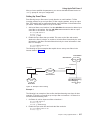
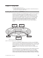
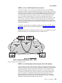
Extended Border Node Connectivity . . . . . . . . . . . . . .
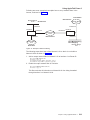
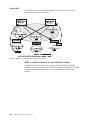
Multiple PUs for Subarea Connected SNA Nodes . . . . . . . . .
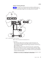
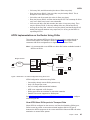
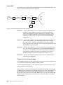
Data Flow in an APPN Configuration Using DLSw Port . . . . . . .
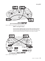
Logical View with Frame Relay Bridged Frame/BAN Connection Network
Support . . . . . . . . . . . . . . . . . . . . . . . .
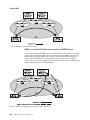
APPN Frame Relay Bridged Frame/BAN Connection Network . . . .
Single Connection Network using BAN with 1 Frame Relay Port . . .
Single Connection Network using BAN with Multiple Frame Relay Ports
Multiple Connection Networks using BAN . . . . . . . . . . . .
Single Connection Network using Bridging with One Frame Relay Port .
Single Connection Network Using Bridging with Multiple Frame Relay
Ports . . . . . . . . . . . . . . . . . . . . . . . . .
Multiple Connection Networks Using Bridging . . . . . . . . . .
Example of Zone Filtering. . . . . . . . . . . . . . . . . .
Example of Network Filtering . . . . . . . . . . . . . . . .
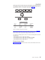
Sample Routing Table . . . . . . . . . . . . . . . . . . .
Sample Neighbor Table . . . . . . . . . . . . . . . . . .
Example of Inclusive Access Control. . . . . . . . . . . . . .
Example of Exclusive Access Control . . . . . . . . . . . . .
Example of Area Routing Filter for Security . . . . . . . . . . .
Example of Blending DECnet Domains . . . . . . . . . . . . .
OSI Network . . . . . . . . . . . . . . . . . . . . . .
NSAP Address Structure . . . . . . . . . . . . . . . . . .
IS-IS NSAP Addressing Interpretation . . . . . . . . . . . . .
GOSIP Address Format . . . . . . . . . . . . . . . . . .
OSI Domain . . . . . . . . . . . . . . . . . . . . . . .
Synonymous Areas . . . . . . . . . . . . . . . . . . . .
Internal and External Routing Metrics . . . . . . . . . . . . .
Next Hop Resolution Protocol (NHRP) Overview . . . . . . . . .
NHRP in a Classic IP Environment . . . . . . . . . . . . . .
NHRP in a Classic IP Environment with non-NHRP Device . . . . .
NHRP in an ELAN Environment . . . . . . . . . . . . . . .
NHRP in an ELAN Environment with LAN Switches . . . . . . . .
NHRP in a Mixed Classical IP and ELAN Environment . . . . . . .
NHRP to an Egress Router . . . . . . . . . . . . . . . . .
Using Disallowed Router-to-Router Shortcuts . . . . . . . . . .
© Copyright IBM Corp. 1994, 1998
. 15
. 24
. 43
. 44
. 45
. 45
46
. 46
. 47
.
.
.
.
.
.
.
.
.
.
.
.
.
.
.
.
.
.
.
.
.
.
.
.
.
47
47
217
219
236
237
255
256
258
260
285
286
287
288
291
292
297
345
348
348
349
350
351
351
356
xi
xii
MRS V3.2 Protocol Config Ref Vol 2
Tables
1.
2.
3.
4.
5.
6.
7.
8.
9.
10.
11.
12.
13.
14.
15.
16.
17.
18.
19.
20.
21.
22.
23.
24.
25.
26.
27.
28.
29.
30.
31.
32.
33.
34.
35.
36.
37.
38.
39.
40.
41.
42.
43.
44.
45.
46.
47.
48.
49.
50.
51.
Implementation of APPN Network Node Functions. . . . . . . . . .
Port Types Supported for APPN Routing . . . . . . . . . . . . .
APPN Configuration Command Summary . . . . . . . . . . . . .
Configuration Parameter List - APPN Routing . . . . . . . . . . .
Configuration Parameter List - High-Performance Routing (HPR) . . . .
Configuration Parameter List - HPR Timer and Retry Options . . . . .
Configuration Parameter List - Dependent LU Requester . . . . . . .
Configuration Parameter List - APPN Node Tuning . . . . . . . . .
Configuration Parameter List - Trace Setup Questions . . . . . . . .
Configuration Parameter List - Node Level Traces . . . . . . . . . .
Configuration Parameter List - Inter-process Signals Traces . . . . . .
Configuration Parameter List - Module Entry and Exit Traces . . . . . .
Configuration Parameter List - General Component Level Traces . . . .
Configuration Parameter List - Miscellaneous Traces . . . . . . . . .
Configuration Parameter List - APPN Node Management . . . . . . .
Configuration Parameter List - APPN ISR Recording Media . . . . . .
Configuration Parameter List - Port Configuration . . . . . . . . . .
Configuration Parameter List - Port Configuration for ATM . . . . . . .
Configuration Parameter List - Port Definition . . . . . . . . . . .
Configuration Parameter List - Port Default TG Characteristics . . . . .
Configuration Parameter List - Port default LLC Characteristics . . . . .
Configuration Parameter List - HPR Override Defaults . . . . . . . .
Configuration Parameter List - Link Station - Detail . . . . . . . . .
Configuration Parameter List - Station Configuration for ATM . . . . . .
Configuration Parameter List - Modify TG Characteristics . . . . . . .
Configuration Parameter List - Modify Dependent LU Server . . . . . .
Configuration Parameter List - Modify LLC Characteristics . . . . . . .
Configuration Parameter List - Modify HPR Defaults . . . . . . . . .
Configuration Parameter List - LEN End Node LU Name . . . . . . .
Configuration Parameter List - Connection Network - Detail . . . . . .
Configuration Parameter List - Connection Network Configuration for ATM
Configuration Parameter List - TG Characteristics (Connection Network)
Configuration Parameter List - APPN COS - Mode Name to COS Name
Mapping - Detail . . . . . . . . . . . . . . . . . . . . . .
Configuration Parameter List - APPN Additional port to Connection
Network . . . . . . . . . . . . . . . . . . . . . . . . .
Configuration Parameter List - APPN Implicit Focal Point . . . . . . .
Configuration Parameter List - APPN Local PU . . . . . . . . . . .
Configuration Parameter List - Routing List Configuration . . . . . . .
Configuration Parameter List - COS Mapping Table Configuration . . . .
TN3270E Configuration Command Summary . . . . . . . . . . .
Configuration Parameter List - Set TN3270E . . . . . . . . . . . .
Configuration Parameter List - Add TN3270E Implicit. . . . . . . . .
Configuration Parameter List - Add TN3270E LU . . . . . . . . . .
Configuration Parameter List - Add TN3270E Map. . . . . . . . . .
Configuration Parameter List - Add TN3270E Port . . . . . . . . . .
Configuration Parameter List - Delete TN3270E LU . . . . . . . . .
Configuration Parameter List - Delete TN3270E Implicit . . . . . . . .
Configuration Parameter List - Delete TN3270E Map. . . . . . . . .
Configuration Parameter List - Delete TN3270E Port . . . . . . . . .
APPN Monitoring Command Summary . . . . . . . . . . . . . .
TN3270E Monitoring Command Summary. . . . . . . . . . . . .
AppleTalk Phase 2 Configuration Commands Summary . . . . . . . .
© Copyright IBM Corp. 1994, 1998
3
25
81
83
89
89
93
97
102
103
108
112
114
119
121
123
125
129
135
140
146
148
149
159
165
168
169
171
172
173
176
180
183
185
186
186
188
191
194
194
197
200
203
204
205
206
206
208
209
212
221
xiii
52.
53.
54.
55.
56.
57.
58.
59.
60.
61.
62.
63.
64.
65.
66.
67.
68.
69.
70.
71.
72.
73.
74.
75.
76.
77.
xiv
AppleTalk Phase 2 Monitoring Command Summary . .
Vines IP Header Fields Summary . . . . . . . . .
Client and Service Node VINES ARP States . . . . .
VINES Configuration Commands Summary . . . . .
VINES Monitoring Command Summary. . . . . . .
DNA IV and DNA V Algorithm Considerations . . . .
NCP Configuration and Monitoring Commands . . . .
IS-IS Multicast Addresses . . . . . . . . . . . .
OSI Configuration Commands Summary . . . . . .
OSI/DECnet V Monitoring Commands Summary . . .
NHRP Configuration Command Summary . . . . . .
NHRP Advanced Configuration Command Summary . .
NHRP Monitoring Command Summary . . . . . . .
NHRP Config Parameter Summary . . . . . . . .
IPV6 Configuration Command Summary . . . . . .
Update Packet-filter Configuration Command Summary .
IPv6 Monitoring Command Summary . . . . . . .
NDP Configuration Command Summary . . . . . .
NDP Monitoring Command Summary . . . . . . .
PIM Configuration Command Summary. . . . . . .
PIM Monitoring Command Summary. . . . . . . .
RIP6 Configuration Command Summary . . . . . .
RIP6 Monitoring Command Summary . . . . . . .
Comparison Protocols . . . . . . . . . . . . .
Protocol Key . . . . . . . . . . . . . . . .
Default Network-Specific Maximum Packet Size . . .
MRS V3.2 Protocol Config Ref Vol 2
.
.
.
.
.
.
.
.
.
.
.
.
.
.
.
.
.
.
.
.
.
.
.
.
.
.
.
.
.
.
.
.
.
.
.
.
.
.
.
.
.
.
.
.
.
.
.
.
.
.
.
.
.
.
.
.
.
.
.
.
.
.
.
.
.
.
.
.
.
.
.
.
.
.
.
.
.
.
.
.
.
.
.
.
.
.
.
.
.
.
.
.
.
.
.
.
.
.
.
.
.
.
.
.
.
.
.
.
.
.
.
.
.
.
.
.
.
.
.
.
.
.
.
.
.
.
.
.
.
.
.
.
.
.
.
.
.
.
.
.
.
.
.
.
.
.
.
.
.
.
.
.
.
.
.
.
.
.
.
.
.
.
.
.
.
.
.
.
.
.
.
.
.
.
.
.
.
.
.
.
.
.
229
235
239
241
245
261
265
288
305
330
359
361
369
373
383
394
398
405
410
411
416
425
431
433
433
435
Notices
References in this publication to IBM products, programs, or services do not imply
that IBM intends to make these available in all countries in which IBM operates. Any
reference to an IBM product, program, or service is not intended to state or imply
that only IBM’s product, program, or service may be used. Any functionally
equivalent product, program, or service that does not infringe any of IBM’s
intellectual property rights may be used instead of the IBM product, program, or
service. Evaluation and verification of operation in conjunction with other products,
except those expressly designated by IBM, are the user’s responsibility.
|
|
|
|
IBM may have patents or pending patent applications covering subject matter in this
document. The furnishing of this document does not give you any license to these
patents. You can send license inquiries, in writing, to the IBM Director of Licensing,
IBM Corporation, North Castle Drive, Armonk, NY 10504-1785, U.S.A.
The licensed program described in this document and all licensed material available
for it are provided by IBM under terms of the IBM Customer Agreement.
|
This document is not intended for production use and is furnished as is without any
warranty of any kind, and all warranties are hereby disclaimed including the
warranties of merchantability and fitness for a particular purpose.
© Copyright IBM Corp. 1994, 1998
xv
xvi
MRS V3.2 Protocol Config Ref Vol 2
|
|
Notice to Users of Online Versions of This Book
|
|
|
|
For online versions of this book, you are authorized to:
v Copy, modify, and print the documentation contained on the media, for use within
your enterprise, provided you reproduce the copyright notice, all warning
statements, and other required statements on each copy or partial copy.
v Transfer the original unaltered copy of the documentation when you transfer the
related IBM product (which may be either machines you own, or programs, if the
program’s license terms permit a transfer). You must, at the same time, destroy
all other copies of the documentation.
|
|
You are responsible for payment of any taxes, including personal property taxes,
resulting from this authorization.
|
|
|
THERE ARE NO WARRANTIES, EXPRESS OR IMPLIED, INCLUDING THE
WARRANTIES OF MERCHANTABILITY AND FITNESS FOR A PARTICULAR
PURPOSE.
|
|
Some jurisdictions do not allow the exclusion of implied warranties, so the above
exclusion may not apply to you.
|
|
Your failure to comply with the terms above terminates this authorization. Upon
termination, you must destroy your machine-readable documentation.
|
|
|
|
© Copyright IBM Corp. 1994, 1998
xvii
xviii
MRS V3.2 Protocol Config Ref Vol 2
Trademarks
The following terms are trademarks of the IBM Corporation in the United States or
other countries or both:
Advanced Peer-to-Peer Networking
AIX
AIXwindows
APPN
VTAM
IBM
Micro Channel
NetView
AS/400
BookManager
PS/2
RS/6000
System/370
Nways
UNIX is a registered trademark in the United States and other countries licensed
exclusively through X/Open Company Limited.
Microsoft, Windows, Windows NT, and the Windows logo are trademarks or
registered trademarks of Microsoft Corporation.
Other company, product, and service names may be trademarks or service marks
of others.
© Copyright IBM Corp. 1994, 1998
xix
xx
MRS V3.2 Protocol Config Ref Vol 2
This manual contains the information you will need to configure bridging and routing
functions on an Nways device . The manual describes all of the features and
functions that are in the software. A specific Nways device might not support all of
the features and functions described. If a feature or function is device-specific, a
notice in the relevant chapter or section indicates that restriction.
This manual supports the IBM 2210 and refers to this product as either “the router”
or “the device.” The examples in the manual represent the configuration of an IBM
2210 but the actual output you see may vary. Use the examples as a guideline to
what you might see while configuring your device.
Who Should Read This Manual: This manual is intended for persons who install
and operate computer networks. Although experience with computer networking
hardware and software is helpful, you do not need programming experience to use
the protocol software.
To get additional information: Changes may be made to the documentation after
the books are printed. If additional information is available or if changes are
required after the books have been printed, the changes will be in a file (named
README) on diskette 1 of the configuration program diskettes. You can view the
file with an ASCII text editor.
About the Software
IBM Nways Multiprotocol Routing Services is the software that supports the IBM
2210 (licensed program number 5801-ARR). This software has these components:
v The base code, which consists of:
– The code that provides the routing, bridging, data link switching, and SNMP
agent functions for the device.
– The router user interface, which allows you to configure, monitor, and use the
Multiprotocol Routing Services base code installed on the device. The router
user interface is accessed locally through an ASCII terminal or emulator
attached to the service port, or remotely through a Telnet session or
modem-attached device.
|
|
|
|
The base code is installed at the factory on the 2210.
v The Configuration Program for IBM Nways Multiprotocol Routing Services
(referred to in this book as the Configuration Program) is a graphical user
interface that enables you to configure the device from a stand-alone workstation.
The Configuration Program includes error checking and online help information.
The Configuration Program is not pre-loaded at the factory; it is shipped
separately from the device as part of the software order.
You can also obtain the Configuration Program for IBM Nways Multiprotocol
Routing Services from the IBM Networking Technical Support home page. See
Configuration Program User’s Guide for Nways Multiprotocol and Access
Services Products, GC30-3830, for the server address and directories.
© Copyright IBM Corp. 1994, 1998
xxi
Conventions Used in This Manual
The following conventions are used in this manual to show command syntax and
program responses:
1. The abbreviated form of a command is underlined as shown in the following
example:
reload
In this example, you can enter either the whole command (reload) or its
abbreviation (rel).
2. Keyword choices for a parameter are enclosed in brackets and separated by the
word or. For example:
command [keyword1 or keyword2]
Choose one of the keywords as a value for the parameter.
3. Three periods following an option mean that you enter additional data (for
example, a variable) after the option. For example:
time host ...
In this example, you enter the IP address of the host in place of the periods, as
explained in the description of the command.
4. In information displayed in response to a command, defaults for an option are
enclosed in brackets immediately following the option. For example:
Media (UTP/STP) [UTP]
In this example, the media defaults to UTP unless you specify STP.
5. Keyboard key combinations are indicated in text in the following ways:
v Ctrl-P
v Ctrl The key combination Ctrl - indicates that you should press the Ctrl key and the
hyphen simultaneously. In certain circumstances, this key combination changes
the command line prompt.
6. Names of keyboard keys are indicated like this: Enter
7. Variables (that is, names used to represent data that you define) are denoted by
italics. For example:
File Name: filename.ext
IBM 2210 Nways Multiprotocol Router Publications
The following list shows the books that support the IBM 2210.
Information updates and corrections: To keep you informed of engineering
changes, clarifications, and fixes that were implemented after the books were
printed, refer to the IBM 2210 home pages at:
http://www.networking.ibm.com/220/220prod.html
Operations and Network Management
SC30-3681
Software User’s Guide
This book explains how to:
xxii
MRS V3.2 Protocol Config Ref Vol 2
v Configure, monitor, and use the IBM Nways Multiprotocol Routing
Services software shipped with the router.
v Use the Multiprotocol Routing Services command-line router user
interface to configure and monitor the network interfaces and link-layer
protocols shipped with the router.
SC30-3992
Using and Configuring Features
SC30-3680
Protocol Configuration and Monitoring Reference Volume 1
SC30-3865
Protocol Configuration and Monitoring Reference Volume 2
These books describe how to access and use the Multiprotocol Routing
Services command-line router user interface to configure and monitor the
routing protocol software and features shipped with the router.
They include information about each of the protocols that the devices
support.
SC30-3682
Event Logging System Messages Guide
This book contains a listing of the error codes that can occur, along with
descriptions and recommended actions to correct the errors.
Configuration
Online help
The help panels for the Configuration Program assist the user in
understanding the program functions, panels, configuration parameters, and
navigation keys.
GC30-3830
Configuration Program User’s Guide for Nways Multiprotocol and Access
Services Products
This book discusses how to use the Configuration Program.
GG24-4446
IBM 2210 Nways Multiprotocol Router Description and Configuration
Scenarios
This book contains examples of how to configure protocols using IBM
Nways Multiprotocol Routing Services.
Safety
SD21-0030
Caution: Safety Information - Read This First
This book provides translations of caution and danger notices applicable to
the installation and maintenance of an IBM 2210.
The following list shows the books in the IBM 2210 Nways Multiprotocol Router
library, arranged according to tasks.
Planning and Installation
GA27-4068
IBM 2210 Introduction and Planning Guide
xxiii
GC30-3867
IBM 2210 Nways Multiprotocol Router Installation and Initial Configuration
Guide
These books are shipped with the 2210. They explain how to prepare for
installation, install the 2210, perform an initial configuration, and verify that
the installation is successful.
These books provide translations of danger notices and other safety
information.
Diagnostics and Maintenance
SY27-0345
IBM 2210 Nways Multiprotocol Router Service and Maintenance Manual
This book is shipped with the 2210. It provides instructions for diagnosing
problems with and repairing the 2210.
|
|
Summary of Changes for the IBM 2210 Software Library
|
|
The following list applies to changes in the software that were made in Version 3.2.
The changes consist of:
|
v New functions:
– IP Version 6
- TCP6, UDP6, Telnet, PING-6 and traceroute-6, ICMPv6, and IPsec
|
|
- Neighbor discovery protocol (NDP) for host auto-configuration
- Static routes, RIPng, Protocol Independent Multicast-Dense Mode
(PIM-DM), and Multicast Listener Discovery (MLD)
- Configured or automatic tunneling of IPv6 packets over IPv4 networks
|
|
|
|
- Support for Ethernet, Token Ring, and PPP interfaces
– Resource ReSerVation Protocol (RSVP)
- Signalling mechanisms that enable applications on IPv4 networks to
reserve network resources to achieve a desired quality of service for packet
delivery
|
|
|
|
|
- Supported on ATM point-to-point SVCs, PPP, Frame Relay, X.25, Token
Ring, and Ethernet
– Binary Synchronous Relay (BRLY) support for BSC interfaces
Binary Synchronous Relay (BRLY) support for tunneling Bisync
Synchronous (BSC) transmissions over a IPv4 network to a partner 2210
or 2212 router
|
|
|
|
|
|
v Enhanced functions:
– Base Services
- Event Logging System (ELS) enhancements to capture, format, and offload
large volumes of ELS messages
- Timed configuration change support from the configuration tool that is
persistent across reloads and restarts
|
|
|
|
|
|
- Packet trace support for PPP, Frame Relay, and V.34 interfaces.
– Bridging support for a multiaccess bridge port for source route bridging over
Frame Relay. The multiaccess port incorporates many DLCIs in a single
bridge port for improved scalability.
– DIALs
|
|
|
|
|
xxiv
MRS V3.2 Protocol Config Ref Vol 2
Summary of Changes
|
|
|
|
|
|
|
|
|
|
|
|
- DIALs support for functions supported by Microsoft Dial-Up Network Clients
v Support for Callback Control Protocol (CBCP)
v Support for Microsoft Point-to-Point Encryption (MPPE) and Microsoft
PPP CHAP (MS-CHAP)
- Virtual connections to suspend and resume dial-up connections when Shiva
Password Authentication Protocol (SPAP) is used
– IP items
- IP precedence/TOS filter enhancements
- Policy-based routing
- Configuration of the IP MTU by interface
- OSPF Enhancements to allow for easier migration of IBM 6611 router
networks
- BGP-4 support for policies per neighbor and additional attributes for path
selection
- DVMRPv3 support
- IGMP prune and grafting support
|
|
|
|
|
|
|
|
|
|
|
|
– ISDN support for callback based on the caller ID and call blocking
– L2TP support for the L2TP client model which allows the 2210 to create an
L2TP tunnel between itself and another router. The tunnel can be used for any
traffic entering the 2210. The L2TP Network Server (LNS) function has also
been enhanced to initiate outgoing calls to the L2TP Network Access
Concentrator (LAC).
– Network Dispatcher items
- Support for stateless UDP applications
|
|
- New protocol advisors for Network News Transfer Protocol (NNTP), Post
Office Protocol (POP3), Simple Mail Transfer Protocol (SMTP), and Telnet
|
|
- While you are balancing TN3270 servers, one of the TN3270 servers may
be in the same 2210 as the Network Dispatcher function
Support for PPP authentication using an ACE/Server
Security Enhancements
- IPsec tunnel-in-tunnel support for creating up to two nested levels of
security associations
- IPsec ESP NULL algorithm support
- IPsec support for setting the don’t fragment bit and propogation of Path
MTU
- Improved dynamic reconfiguration for IPsec
Mixed media multi-link PPP support for bundling PPP leased line, ISDN,
V.25bis, and V.34 connections
APPN enhancements
- APPN SDLC Secondary multipoint support
- Configuration of the APPN transmission group (TG) number for all link
station types
- Support for the APPN Ping (APING) command in Talk 5
- New trace options
TN3270 Enhancements
|
|
–
–
|
|
|
|
|
|
|
|
–
|
–
|
|
|
|
|
|
|
|
–
Note: These TN3270 enhancements will not be available in the initial release
of V3.2, but will be available on the 2210 Web server by 12/31/98.
xxv
Summary of Changes
- TN3270 LU pooling support that allows SNA LUs to be grouped into named
pools
- TN3270 IP address to LU name mapping
- Self-Defining Dependent LUs (SDDLU) and Dynamically Defined
Dependent LUs (DDDLU) support
- Multiple TCP port support
– DLSw enhancements
- Support for duplicate MAC addresses
- Support to delay polling of SDLC devices until contacted by the remote
SDLC device
– X.25 enhancements
Configuration support for a defining a range of PVCs
|
|
|
|
|
|
|
|
|
|
|
|
|
– Frame Relay support for switched virtual circuits
– IPXWAN support on Frame Relay permanent virtual circuits (PVCs), including
support for numbered RIP, unnumbered RIP, and static routing
v Clarifications and corrections
|
|
The technical changes and additions are indicated by a vertical line (|) to the left
of the change.
|
|
|
|
Editorial Changes
|
|
This edition continues a number of editorial changes to this book and the other
software books that will:
|
|
v
v
v
v
|
The first step in reorganization has been completed as follows:
|
|
|
|
|
v The part titled Understanding, Using and Configuring Features has been
moved into the Using and Configuring Features book from the Software User’s
Guide.
v The chapters on using, configuring, and monitoring the DIALs feature have been
moved into the Using and Configuring Features book.
|
|
|
This reorganization will take place over a number of editions. If you would like to
comment on these changes, please mail or fax your comments on the form for
readers’ comments at the back of this publication.
|
|
Reorganize the material
Remove any unnecessary and redundant information
Improve retrievability
Add additional clarification to some information
Getting Help
At the command prompts, you can obtain help in the form of a listing of the
commands available at that level. To do this, type ? (the help command), and then
press Enter. Use ? to list the commands that are available from the current level.
You can usually enter a ? after a specific command name to list its options. For
example, the following information appears if you enter ? at the * prompt:
*?
|
|
|
|
|
|
BREAKPOINT
DIVERT output from process
FLUSH output from process
HALT output from process
xxvi
MRS V3.2 Protocol Config Ref Vol 2
Summary of Changes
|
|
|
|
|
|
|
|
|
INTERCEPT character is
LOGOUT
MEMORY statistics
RESTART
STATUS of process(es)
TALK to process
TELNET to IP-Address
Exiting a Lower Level Environment
The multiple-level nature of the software places you in secondary, tertiary, and even
lower level environments as you configure or operate the 2210. To return to the
next higher level, enter the exit command. To get to the secondary level, continue
entering exit until you receive the secondary level prompt (either Config> or +).
For example, to exit the IP protocol configuration process:
IP config> exit
Config>
If you need to get to the primary level (OPCON), enter the intercept character (Ctrl
P by default).
xxvii
Summary of Changes
xxviii
MRS V3.2 Protocol Config Ref Vol 2
Chapter 1. APPN
This chapter describes APPN and includes the following sections:
v “What is APPN?”
v “What APPN Functions Are Implemented on the Router?” on page 3
v “APPN Network Node Optional Features” on page 6
v “Supported DLCs” on page 25
v “Router Configuration Process” on page 25
v “APPN Configuration Notes” on page 49
What is APPN?
Advanced Peer-to-Peer networking (APPN) extends the SNA architecture by
enabling Type 2.1 (T2.1) nodes to communicate directly without requiring the
services of a SNA host computer.
Peer-to-Peer Communications
T2.1 nodes can activate connections with other T2.1 nodes and establish LU-LU
sessions with other nodes. The relationship between a pair of T2.1 nodes is
referred to as a peer relationship because either side can initiate communication.
Prior to APPN, a T2.1 node could communicate directly with another T2.1 node, but
required the services of a centralized SNA host to locate its partner and any
associated resources. All routes between the two nodes were predefined. APPN
enhanced the T2.1 node function by:
v Requiring network resources to be defined only at the node where they are
located
v Distributing information about these resources throughout the network as needed
v Dynamically generating routes between nodes using current information about
the network’s topology and the desired class of service
APPN Node Types
The APPN architecture allows four types of nodes in a network:
v APPN network nodes
v APPN end nodes
v Low-entry networking (LEN) end nodes
v PU 2.0 nodes supported by DLUR
The router can be configured as an APPN network node that supports connections
with all four node types. The router cannot function as an end node for APPN.
APPN Network Node
An APPN network node provides directory and routing services for all resources
(LUs) in its domain. A network node’s domain consists of:
v Local resources owned by the node
© Copyright IBM Corp. 1994, 1998
1
APPN
v A control point (CP), which manages the node’s resources
v Resources owned by APPN end nodes and LEN end nodes that use the services
of the network node
APPN network nodes also:
v Exchange information about the topology of the network. This information is
exchanged each time network nodes establish a connection or when there is a
change in the topology of the network (such as when a network node is
deactivated, brought on line, or when a link is congested or fails). When a
network node receives a topology update, it broadcasts this information to other
active and network nodes with which it has CP-CP sessions.
v Act as intermediate nodes, receiving session data from one adjacent node and
passing that data on to the next adjacent node along the route.
As a network node, the router can act as a server to attached APPN end nodes and
LEN end nodes and provide functions that include:
Directory services
The network node, communicating with other network nodes, can locate a
resource in the network on behalf of an APPN end node. The network node
also maintains a local directory of APPN and LEN end node resources that
it can search on behalf of an attached APPN end node, attached LEN end
node, or other network nodes.
Topology and Routing services
At the request of an APPN end node, the network node dynamically
determines the route from an origin logical unit (LU) to a destination LU in
the network. The network node also maintains information on other network
nodes and the routes to those nodes. The route is based on the current
topology of the network.
Management services
The network node can pass alert conditions to a designated focal point to
allow centralized problem management. The network node is responsible
for processing alert conditions for all the resources in its domain. “Managing
a Network Node” on page 17 describes this process.
APPN End Nodes
An APPN end node provides limited directory, routing, and management services
for logical units (LUs) associated with the node. An APPN end node selects a
network node to be its network node server. If the network node agrees to act as
the APPN end node’s server, the end node can register its local resources with the
network node. This enables the network node server to intercept and pass along
search requests for resources located on the APPN end node.
The APPN end node and its network node server communicate by establishing
CP-CP sessions. An APPN end node may be connected to a number of network
nodes, but only one of these nodes acts as the APPN end node’s server at any one
time.
The APPN end node forwards all requests for unknown resources to the network
node server. The network node server, in turn, uses its search facilities to locate the
requested resource and calculate a route from the APPN end node to the resource.
2
MRS V3.2 Protocol Config Ref Vol 2
APPN
LEN Nodes
A LEN node is a T2.1 node without APPN extensions. A LEN node can establish
peer connections with other LEN nodes, APPN end nodes, and APPN network
nodes, as long as all of the required destination LUs are registered with the LEN
node. A LEN node can also serve as a gateway between an APPN network and a
SNA subarea network.
Because a LEN node cannot establish CP-CP sessions with an APPN network
node server, it cannot register its resources with the server or request that the
server search for a resource and dynamically calculate a route to that resource. A
LEN node may indirectly use the directory and routing services of a network node
by pre-defining remote LUs (owned by nonadjacent nodes) as being located on an
APPN network node, although the actual location may be anywhere in the network.
When the LEN node needs to initiate a session with the remote LU, it sends a
session activation request (BIND) for the LU to the network node. In this case, the
network node acts as the LEN node’s network node server, locating the requested
resource, calculating a route, and forwarding the BIND to its correct destination.
When configuring the router network node, you can specify the names of LUs that
are associated with an attached LEN end node. These LU names reside in the
router network node’s local directory. If the router network node receives a request
to search for one of these LEN end node resources, it will be able to find the LU in
its local directory and return a positive response to the node originating the search.
To reduce the number of LU names you need to specify for an attached LEN end
node, the router supports the use of generic LU names, which allow a wildcard
character to represent a portion of an LU name.
PU 2.0 Nodes
A PU 2.0 node is a type T2.0 node containing dependent LUs. PU 2.0 nodes are
supported by the Dependent LU Requestor (DLUR) function which is implemented
by an APPN end node or network node. PU 2.0 nodes require the services of a
system services control point, which is made available through the DLUR-enabled
APPN node. Note that APPN nodes can contain dependent LUs supported by the
DLUR function. However, the router does not contain dependent LUs.
What APPN Functions Are Implemented on the Router?
The router implements the APPN Release 2 base architecture functions as defined
in the Systems Network Architecture APPN Reference. The APPN network node
functions implemented by the router are summarized in Table 1. Notes on specific
functions follow the table. For a description of the APPN management services
supported by the router, see “Managing a Network Node” on page 17.
APPN uses LU 6.2 protocols to provide peer connectivity between CP-CP session
partners. The router network node implements the LU 6.2 protocols required for
CP-CP sessions and those used in sessions between a network node CP and its
network management focal point. The router implementation of APPN does not
provide an application program interface to support user-written LU 6.2 programs.
Table 1. Implementation of APPN Network Node Functions
APPN Function
Session services and supporting functions
Multiple CP-CP sessions
Yes
No
Notes
X
Chapter 1. APPN
3
APPN
Table 1. Implementation of APPN Network Node Functions (continued)
APPN Function
Yes
No
Notes
Mode name to class of service (COS) mapping
Limited resource link stations
BIND segmentation and reassembly
Session-level security
Intermediate session routing
X
X
X
X
1
2
3
4
Intermediate session routing
Routing of dependent LU sessions
Fixed and adaptive session-level pacing
RU segmentation and reassembly
Directory services
X
X
X
X
5
Broadcast searches
Directed searches
Directory caching
Safe storage of directory services cache
Central directory server
Central directory client
Registration of APPN EN LUs with network node server
Definition of LEN node LUs on network node server
Use of wild cards to define attached LEN node resources
Accept multiple “resource found” conditions
Network node server for DLUR EN - Option set 1116
Topology and routing services
X
X
X
Topology exchange
Periodic topology broadcasts
Topology database maintenance
Topology awareness of CP-CP sessions
Randomized route computation
Cached routing trees
Safe storage of topology database
Garbage Collection Enhancements
Connectivity
X
X
X
X
X
X
Connection network definition
Multiple transmission groups
Parallel transmission groups
Management services
X
X
X
Multiple domain support (MDS)
Explicit focal point
Implicit focal point
Held alerts
SSCP-PU sessions with focal points
SNA/MS problem diagnosis data in alerts
X
X
X
X
X
X
X
X
6
7
7
8
9
10
11
X
X
12
X
X
X
X
X
X
Notes:
1. New mode names can be defined on the router using the Command Line
interface. These new mode names can be mapped to existing Class of Service
(COS) definition names or to new COS definitions, which may be defined using
the Configuration tool.
2. Limited resource link stations are supported for:
v connection network links
4
MRS V3.2 Protocol Config Ref Vol 2
APPN
v X.25 SVC links
v PPP links running over ISDN, V.25bis, or V.34
v Frame relay links running over ISDN
v ATM SVC.
3. When the router activates a TG to an adjacent node, it negotiates with that
node the maximum message size that can be sent across the TG. If a BIND
message is larger than the negotiated message size, the router segments the
BIND. Segmentation only occurs if the adjacent node is capable of
reassembling the BIND. The router supports BIND reassembly.
4. A session level security feature can be enabled for connections between the
router network node and an adjacent node. Both partners in the connection
require a matching hexadecimal key that enables each node to verify its
partner before the connection is established.
5. When routing session data to an adjacent node, the router segments a
request/response unit (RU) if the message unit exceeds the maximum
message size that can be sent across the transmission group. If the router
receives a segmented RU, the node reassembles it.
6. After successfully locating a resource in the APPN network, the router stores
or caches this information in its local directory database for future use.
However, the router does not save these cached directory entries to a
permanent storage medium, such as a disk, to provide for recovery if the node
fails.
7. The router cannot be used as a central directory server for an APPN network.
The router is capable of using a central directory server, however, to obtain
directory information about the location of a resource in the network.
8. To prevent other network nodes from discarding information about the router
from their topology databases, the router creates a topology database update
(TDU) about itself and its locally-owned transmission groups every 5 days and
broadcasts this TDU to network nodes.
9. An interval timer is associated with every resource entry in the router’s network
topology database. If the router does not receive any information about a
resource within 15 days, it discards the entry for that resource from the
database.
10. If there is more than one least-weight route from an origin LU to a destination
LU for a given class of service, the router randomly selects one of these routes
for the session. This practice helps distribute the flow of traffic in the network.
11. The router maintains a copy of the network topology database. The database
identifies the available routes to other network nodes for a particular class of
service. When the router needs to calculate a route to a network node or to an
end node adjacent to that network node, it uses information in the topology
database to generate a routing tree for that network node. The routing tree
identifies the optimal routes to the network node for the class of service
required.
When the router generates a new routing tree, it stores that tree in a cache.
When the router receives a service request, it checks this cache first to see if a
route has been computed. Use of the cache reduces the number of route
calculations required. When the router receives topology information that
invalidates a routing tree, it discards the tree. The router recalculates the tree
as needed and caches the new tree.
12. The router can be defined as a member of a connection network on Ethernet
ports, Token-Ring ports, Frame Relay BAN ports, Enterprise Extender Support
for HPR over IP, and ATM ports.
Chapter 1. APPN
5
APPN
APPN Network Node Optional Features
In addition to the base APPN Architecture functions, the router also implements the
following option set towers and new functions:
087
Garbage Collection Enhancements
1002
Adjacent Link Station name
1007
Parallel TGs
1012
LU name = CP name
1016
Extended Border Node
1061
Prerequisites for SS Extensions for NNS Support
1063
SS Extensions NNS Support
1067
Dependent LU Requester
1071
Generalized ODAI Usage
1101
Preloaded Directory Cache
1107
Central Resource Registration (of LUs)
1116
Network Node Server support for DLUS-Served LU registration
1119
Report Branch Topology to a Manager
1120
Branch Awareness
1121
Branch Extender
1200
Tree Caching and TG Caching
1400
High-Performance Routing (HPR)
1401
Rapid Transport Protocol (RTP)
1402
Control Flows over RTP
1405
HPR Border Node
Node performance tuning
Node service traces
Accounting and node statistics collection
High-Performance Routing
HPR is an enhancement to APPN architecture that provides better performance
over high speed, low error rate links using existing hardware. HPR replaces the
normal APPN intermediate session routing (ISR) with a Network Control Layer
(NCL) containing a new type of source routing function called automatic network
routing (ANR). The complete HPR route is contained in the ANR packet allowing
intermediate routing nodes to route the packets with less processing overhead and
storage.
HPR also eliminates the error recovery and flow control (session-level pacing)
procedures for each link between nodes and moves the error recovery and
flow/congestion control procedures to the end-points of an HPR connection. A
transport layer using a new error recovery procedure called Rapid Transport
6
MRS V3.2 Protocol Config Ref Vol 2
APPN
Protocol (RTP) is used by the endpoints of the HPR connection. HPR intermediate
nodes have no session or RTP connection awareness. This new transport layer
features:
v Selective retransmission error recovery procedure
v Segmentation and reassembly
v Adaptive Rate-Based (ARB) flow and congestion control mechanism that meters
data onto a route that allows efficient utilization of network resources while
minimizing congestion. ARB uses a preventative rather than reactive approach to
flow and congestion control.
v Non-disruptive Path Switch (NDPS) function that automatically reroutes traffic
around node or link failures without disrupting end user sessions.
v Detection of Forward Explicit Congestion Notification (FECN) bit set, allowing
RTP’s adaptive rate-based flow and congestion control algorithm to adjust the
data send rate. This algorithm prevents traffic bursts and congestion, maintaining
a high level of throughput.
The router implements both ANR routing and Rapid Transport Protocol. Therefore,
the router can function both as an intermediate routing HPR node and as an HPR
connection endpoint node.
Interoperability
HPR uses APPN network control functions including class of service (COS)-based
least-weight route calculation and transmission priority. HPR interoperates
seamlessly with APPN ISR:
v The network automatically adapts to the presence of HPR-capable nodes and
HPR-enabled links.
v An APPN network can have any mix of ISR and HPR links, although the greatest
benefit of HPR is realized when the network has three or more HPR-enabled
nodes with two or more HPR-capable links back-to-back. This allows the middle
HPR node to be an HPR intermediate node and use only ANR routing, allowing
session data to be routed through the middle node using only NCL.
v A given session route can be made up of a combination of ISR and HPR links.
v HPR uses the same TG and node characteristics for least-weight route
calculation as APPN ISR. No special consideration is given to HPR capable
nodes or links other than their potentially improved characteristics (such as
higher effective capacity if a higher speed link).
Traffic types
APPN ISR uses the QLLC protocol for X.25 direct data link control, the IEEE 802.2
LLC Type 2 protocol for token-ring, Ethernet, PPP, and frame relay and SDLC
protocol for the SDLC data link control. APPN HPR, which is supported on
token-ring, Ethernet, PPP, and frame relay, does not use LLC Type 2 protocol, but
does use some functions of an APPN link station for XID and inactivity timeout. A
single APPN link station is therefore used for ISR or HPR. Different mechanisms
are used to distinguish between ISR and HPR traffic depending upon the DLC type:
v For token-ring and Ethernet LAN ports:
Each protocol that uses a port must have a unique SAP address, with the
exception of DLSw (which may use the same SAP address as other protocols
because DLSw frames will not be destined for the local MAC address, but rather
a DLSw MAC address). A unique SAP address identifies the APPN link station
for HPR traffic (Local HPR SAP address parameter). If ISR traffic is destined for
a link station, then a different SAP address (Local APPN SAP address
Chapter 1. APPN
7
APPN
parameter) must be used. The ISR traffic uses LLC Type 2 LAN frames. The
HPR traffic is handled in similar fashion to LLC Type 1 LAN frames and must
have a different SAP address.
The default SAP address for HPR traffic is X'C8'. If X'C8' has already been used
by another protocol on a port, the default must be overridden.
Note: There is only one APPN link station even though APPN ISR and HPR
traffic use different SAP addresses.
v For Frame Relay ports:
APPN ISR traffic and APPN HPR traffic transferred over a frame relay data link
connection supports both the RFC 1490 bridged frame format and the RFC 1490
routed frame format.
– RFC 1490 routed frame format
APPN ISR traffic will be transferred over a frame relay data link connection
using the connection-oriented multiprotocol encapsulation method defined in
RFC 1490 using:
- NLPID = X'08' (Q.933 encoding)
- L2PID = X'4C80' (Layer 2 protocol identifier indicating 802.2 LLC)
- L3PID = X'7083' (Layer 3 protocol identifier indicating SNA-APPN/FID2)
APPN HPR traffic transferred over a frame-relay data link connection does not
use IEEE 802.2 LLC. It uses a different multiprotocol encapsulation as defined
in RFC 1490 using:
- NLPID = X'08' (Q.933 encoding)
- L2PID = X'5081' (Layer 2 protocol identifier for no Layer 2 protocol)
- L3PID = X'7085' (Layer 3 protocol identifier indicating SNA-APPN/HPR)
APPN HPR does not use a SAP for traffic transferred using the RFC 1490
routed frame format because there is no Layer 2 protocol.
– RFC 1490 Bridged format
APPN HPR uses a SAP for traffic transferred using the RFC 1490 bridged
frame format.
v For PPP ports:
– APPN ISR traffic uses 802.2 LLC over the PPP connection.
– Since there is no layer 2 protocol used in HPR’s RFC 1490 encapsulation, no
SAP is used for HPR traffic.
v For ATM ports:
– APPN ISR traffic is not supported over native ATM ports. However, two types
of APPN traffic as defined by RFC 1483 are supported:
- During link station bring up, XIDs are transported using the following frame
format:
v NLPID = X'09'
v Layer 2 protocol ID = X'4C80' (802.2 LLC header present)
v Layer 3 protocol ID = X'7083' SNA APPN (FID2) including XID3
- HPR traffic is transported using the following frame format:
v NLPID = X'09'
v Layer 2 protocol ID = X'4C80' (802.2 LLC header present)
8
MRS V3.2 Protocol Config Ref Vol 2
APPN
v Layer 3 protocol ID = X'7085' SNA APPN/HPR (NLP)
v Enterprise Extender Support for HPR over IP
Refer to Table 2 on page 25 for a list of DLCs that support HPR.
Note: HPR is not supported over SDLC, X.25, or DLSw ports.
Dependent LU Requester (DLUR)
The DLUR option extends the support of T2.0 or T2.1 devices containing dependent
LUs to APPN nodes. The DLUR function on an APPN network node or an APPN
end node works in conjunction with a dependent LU server (DLUS) in a mixed
APPN/subarea network. The DLUS function may reside in some other part of the
mixed network from the DLUR.
The dependent LU flows (SSCP-PU and SSCP-LU) are encapsulated over an LU
6.2 (CP-SVR) pipe established between the DLUR APPN node and the DLUS
SSCP. The CP-SVR pipe is made up of a pair of LU 6.2 sessions using a new
CPSVRMGR mode between the DLUR and the DLUS. This pipe brings the SSCP
function (in the DLUS) to the DLUR APPN node where it can be made available to
attached T2.0/T2.1 nodes containing dependent LUs.
The dependent LU will appear to be located within the domain of the serving SSCP.
Session initiation flows will be emulated from the DLUS, but session bind and data
paths will be calculated directly between the dependent LU and its session partner.
This path may or may not traverse the serving DLUS node.
Set the adjacent node type parameter to PU 2.0 Node when defining a link station
to a T2.0 adjacent node containing dependent LUs. Set the adjacent node type
parameter to APPN end node or LEN end node when defining a link station to a
T2.1 adjacent node containing dependent LUs.
See Table 2 on page 25 for the types of ports providing connection to the
downstream PU (DSPU) that are supported.
Functions Supported
The APPN DLUR option includes the following functions:
v Support for SDLC-attached downstream T2.0 nodes containing dependent LUs
that do not support XID exchange.
v Support for downstream T2.0 nodes containing dependent LUs that respond with
XID type 0 and XID type 1.
v Support for downstream T2.1 nodes containing dependent LUs that respond with
XID type 3.
v Support for dependent LUs that is equivalent to the support provided by the
Subarea environment for:
– Activating PUs and their LUs
– Locate and be located by other LUs in an APPN or subarea network
– Determine LU’s characteristics
– Allow terminal operators to logon to applications both in APPN and subarea
networks
– SSCP takeover
Chapter 1. APPN
9
APPN
– Uninterrupted LU-LU sessions, if the supporting DLUS (SSCP) fails
– SLU init, PLU init, and Third-party init
Restrictions
The DLUR option, as implemented on the router network node, has the following
functional restrictions:
v Only secondary LUs (SLUs) can be supported by the DLUR function. An LU
supported by DLUR cannot function as a primary LU (PLU). Therefore, the
downstream physical unit (DSPU) should be configured as secondary.
v Because only SLUs are supported, Network Routing Facility (NRF) and Network
Terminal Option (NTO) are not supported.
v Extended recovery facility (XRF) and XRF/CRYPTO are not supported.
v You must be able to establish an APPN-only or APPN/HPR-only session between
DLUS and DLUR. The CPSVRMGR session cannot pass through a subarea
network.
VTAM Considerations for DLUR
The following are example VTAM Switched Major Node definitions for DLUR. You
should note that PATH statements are necessary only if VTAM is initiating the
connection to the DSPU.
You should refer to VTAM Resource Definition Reference SC31-6427, for details of
the DLC parameter statements for the Switched Major Node definitions.
DABDLURX VBUILD TYPE=SWNET,MAXGRP=400,MAXNO=400,MAXDLUR=20
************************************************************************
*IN THE DLCADDR, THE 'SUBFIELD_ID' = CV SUBFIELD OF THE CV91
*
* MINUS 0X90.
*
*FOR EXAMPLE, THE CV94 SUBFIELD IS CODED ON DLCADDR=(4,X,...
*
************************************************************************
************************************************************************
* Following are PU Statements for 2.0 and for 2.1
************************************************************************
************************************************************************
* 2.0 PU STATEMENT
************************************************************************
*PU20RT PU ADDR=05,PUTYPE=2,MAXPATH=8,ANS=CONT,USSTAB=AUSSTAB,
*
ISTATUS=ACTIVE,MAXDATA=521,IRETRY=YES,MAXOUT=7,
*
PASSLIM=5,IDBLK=017,IDNUM=00035,MODETAB=AMODETAB
*
LOGAPPL=ECHO71,DLOGMOD=M23278I1
************************************************************************
* Path statements are not required if the DSPU is initiating the
* connection to VTAM
************************************************************************
*PU20LU1 LU
LOCADDR=2
11
*PU20LU2 LU
LOCADDR=3
*PU20LU3 LU
LOCADDR=4
************************************************************************
* 2.1 PU STATEMENT
************************************************************************
*PU21RT PU ADDR=06,PUTYPE=2,CPNAME=PU21RT,ANS=CONT,MAXPATH=8,
*
ISTATUS=ACTIVE,USSTAB=AUSSTAB,MODETAB=AMODETAB
*
LOGAPPL=ECHO71,DLOGMOD=M23278I 1
************************************************************************
************************************************************************
*
* Following are examples of path statement coding for various
* DLC types.
*
* There is no difference in the path statement definitions
* between a PU 2.0 and a PU 2.1
*
* Path statements are required if VTAM is initiating the connection
* to the DSPU.
*
************************************************************************
************************************************************************
10
MRS V3.2 Protocol Config Ref Vol 2
APPN
* Below is SDLC
************************************************************************
*A20RT PATH PID=1,
*
DLURNAME=GREEN,
*
DLCADDR=(1,C,SDLCNS),
*
DLCADDR=(2,X,5353), 2 **port name
*
DLCADDR=(3,X,C1)
3a**station address
************************************************************************
* Below is Frame Relay
************************************************************************
*A20RT PATH PID=2,
*
DLURNAME=GREEN,
*
DLCADDR=(1,C,FRPVC),
*
DLCADDR=(2,X,4652303033), 2**port name
*
DLCADDR=(3,X,04),
3**SAP address
*
DLCADDR=(4,X,0024)
4**DLCI
************************************************************************
* Below is Frame Relay BAN
************************************************************************
*A20RT PATH PID=3,
*
DLURNAME=GREEN,
*
DLCADDR=(1,C,FRPVC),
*
DLCADDR=(2,X,4652303033),
2**port name
*
DLCADDR=(3,X,04),
3**SAP address
*
DLCADDR=(4,X,0024),
4**DLCI
*
DLCADDR=(6,X,400000000001) 5**MAC addr
************************************************************************
* Below is DLSw
************************************************************************
*A20RT PATH PID=3,
*
DLURNAME=GOLD,
*
DLCADDR=(1,C,TR),7
*
DLCADDR=(2,X,444C53323534),2**port name
*
DLCADDR=(3,X,04),
3**SAP address
*
DLCADDR=(4,X,400000000001) 6**MAC address
*
*************************************************************************
** Below is Token Ring
*************************************************************************
*PATHT20 PATH PID=1,
*
DLURNAME=RED,
*
DLCADDR=(1,C,TR),
*
DLCADDR=(2,X,5452303030), 2**port name
*
DLCADDR=(3,X,04),
3**SAP address
*
DLCADDR=(4,X,400000011088) 6**MAC address
*************************************************************************
** Below is Ethernet
*************************************************************************
*PATHE20 PATH PID=1,
*
DLURNAME=PURPLE,
*
DLCADDR=(1,C,ETHERNET),
*
DLCADDR=(2,X,454E303030), 2**port name
*
DLCADDR=(3,X,20),
3**SAP address
*
DLCADDR=(4,X,400000011063) 6**MAC address
************************************************************************
* Below is X25 SVC
************************************************************************
*A20RT PATH PID=3,
*
DLURNAME=GREEN,
*
DLCADDR=(1,C,X25SVC),
*
DLCADDR=(2,X,583235303033), 2**port name
*
DLCADDR=(4,X,C3),
8**Protocol identifier
*
DLCADDR=(21,X,000566666),9**Destination DTE address
************************************************************************
* Below is X25 PVC
************************************************************************
*A20RT PATH PID=3,
*
DLURNAME=GREEN,
*
DLCADDR=(1,C,X25PVC),
*
DLCADDR=(2,X,583235303033), 2**port name
*
DLCADDR=(3,X,0001)
10**Logical channel number
************************************************************************
************************************************************************
************************************************************************
* LU statements
************************************************************************
************************************************************************
*PU21LU1 LU
LOCADDR=2
11
Chapter 1. APPN
11
APPN
*PU21LU2 LU
LOCADDR=3
*PU21LU3 LU
LOCADDR=4
************************************************************************
Notes:
1 The difference between PU statement coding is:
– For 2.0 definitions, the PU statement has IDBLK=...,IDNUM=....
– For 2.1 definitions, the PU statement has CPNAME=....
2 Port name in ASCII defined on the router and used by DSPU
3 SAP of DSPU (noncanonical, except for Ethernet)
3a Station address for SDLC
4 DLCI must have 4 digits because it is a half-word
5 MAC address of the DSPU (noncanonical) for frame relay BAN
6 MAC address of the DSPU (noncanonical, except for Ethernet MAC
address, which is canonical)
7 DLSw appears to VTAM like a token ring DLC
8 Protocol identifier
9 Destination DTE address (000566666, where:
00 is fixed
05 is the length of the DTE address
66666 is the DTE address)
10 Logical channel number. It must have 4 digits because it is a
halfword.
11 LU coding
See “TN3270E Server” on page 20 for an example of an internal PU path
statement.
|
|
APPN Connection Network
When nodes are attached to a shared-access transport facility (SATF), any-to-any
connectivity is possible. This any-to-any connectivity allows direct connections
between any two nodes, eliminating routing through intermediate network nodes
and the corresponding data traversing the SATF multiple times. To achieve this
direct connectivity, however, TGs must be defined on each node for all the other
possible partners.
Defining connections between all possible pairs of nodes attached to the SATF
results in a large number of definitions (increasing on the order of the square of the
number of nodes involved) and also a large number of topology database updates
(TDUs) flowing in the APPN network. To alleviate these problems, APPN allows
nodes to become members of a connection network to represent their attachment to
an SATF. Session traffic between two nodes that have been defined as members of
a connection network can be routed directly, without passing through a network
node (achieves direct connectivity). To become a member of a connection network,
an APPN node’s port must be ″attached″ to a Connection Network by defining a
connection network interface. When the port is defined, a Connection Network TG
is created by the APPN component to identify the direct connection from the port to
the SATF (i.e. the connection network). This TG is not a conventional TG as in the
case of defined link stations, but rather represents the connection to the Connection
Network in the topology database.
12
MRS V3.2 Protocol Config Ref Vol 2
APPN
Note: TGs for end nodes are not contained in the network topology database, but
are contained in the node’s local topology database. TDUs do not flow
through the network when a connection is established through a Connection
Network or when an end node is made a member of a Connection Network.
Because the connectivity is represented by a TG from a given node to a
Connection Network, normal topology and routing services (TRS) can be used for
the network node server to calculate the direct path between any two nodes
attached to the SATF (with TGs to the same Connection Network). DLC signaling
information is returned from the destination node during the normal locate process
to enable the origin node to establish a connection directly to the destination node.
Therefore, to achieve direct connectivity on an SATF, instead of each node on the
SATF being defined (or connected) to each other, each node is connected to a
Connection Network. The Connection Network is often visualized as a virtual node
on the SATF to which all other nodes are attached. This model is frequently used
and, in fact, the term Virtual Routing Node (VRN) is often interchanged with the
term Connection Network.
When a connection network is defined, it is named. This name then becomes the
CP name of the VRN and must follow all the requirements of any CP name. See
Table 23 on page 149 for a list of these requirements.
Restrictions
v The same connection network (VRN) can be defined on only one LAN. The same
VRN can be defined on multiple ports having the same characteristics to the
same LAN however.
v There is only one connection network TG from a given port to a given connection
network’s VRN.
v Because the VRN is not a real node, CP-CP sessions cannot be established with
or through a VRN.
v When a connection network is defined on the router network node, a fully
qualified name is specified for the connection network name parameter. Only
connection networks with the same network ID as the router network node may
be defined. The network ID of the VRN is then the same as the network ID of the
router network node.
Branch Extender
The Branch Extender (BrNN) function is designed to optimize the connection of a
branch office to an APPN WAN backbone network. The BrNN isolates all the end
nodes on one or more branch office LANs from the backbone WAN. The domain of
a BrNN may contain only end nodes and cascaded BrNNs. The domain of a BrNN
does not contain network nodes or nodes with DLUR.
When configuring a BrNN, configure link stations to the backbone to be uplinks.
This causes the BrNN to appear as a conventional end node to the backbone. From
the perspective of the backbone, all resources in the domain of the BrNN appear to
be owned by the BrNN, hiding the topology of the BrNN’s domain from the
backbone and reducing the number of broadcast locates in the backbone.
A BrNN presents a conventional network node interface over downlinks. End nodes
in the domain of the BrNN register their resources with the BrNN and use the BrNN
as a conventional network node server.
Chapter 1. APPN
13
APPN
A BrNN accomplishes:
v Reduction of the number of network nodes in a large APPN network.
v Hidden branch office topology from the WAN.
v Direct, peer-to-peer communication between defined branches connected to the
same connection network.
v Reduces CP-CP session traffic on the WAN link.
The following are limitations of Branch Extender:
v Network nodes are allowed to connect only over links that a BrNN defines as
uplinks.
v Only end nodes or cascaded BrNNs may be attached to a BrNN downlink.
Border nodes acting as end nodes and DLUR nodes may not be attached to a
BrNN downlink.
v A node cannot connect to a Branch Extender over an uplink and a downlink at
the same time.
v A BrNN can have CP-CP sessions with only one network node at a time.
Extended Border Nodes
Extended Border Nodes (BNs) allow networks with different network IDs to connect
to one another. CP-CP sessions will be established across the network boundaries,
and directory services flows and session establishment will be allowed to span the
interconnected networks. Topology information will not be exchanged across the
network boundary. This allows networks with different network IDs to establish
CP-CP sessions and provides topology isolation between different networks.
In addition to allowing networks with different network IDs to interconnect, BNs
provide a mechanism to subdivide networks with the same network ID into smaller
“topology subnetworks”. This subdivision provides topology isolation between the
two subnetworks while allowing directory services flows and sessions to span the
subnetwork boundaries.
There must be a BN on one side of the subnetwork boundary in order to use this
function. When a BN connects to a non-native NN, the BN looks like an EN to the
non-native NN, even though the BN is actually a NN.
There may be two BNs, one on each side of the boundary, cooperating to perform
this function. When two BNs connect across a subnetwork boundary, the BN will
look like a NN to the non-native BN.
A BN will appear to be the NN server for all non-native resources accessible
through the BN. This allows the existing APPN directory caching and route
calculation functions to work, while enabling the BN to intercept and modify all
Locate and BIND flows which cross an inter-subnetwork TG (ISTG).
BNs implement piece-wise optimal session route calculation. Each subnetwork
calculates its own part of the session’s route selection control vector (RSCV) to the
entry point in the next non-native subnetwork. While the RSCV will be optimal
through the native subnetwork, there is no guarantee that the end-to-end session
path will be optimal.
14
MRS V3.2 Protocol Config Ref Vol 2
APPN
Network Topology Example
Figure 1 shows many of the connectivity options provided by the BN function. In
general, you can get from any network to any other network except that NetF can
only reach network NetE and NetE is the only network that can reach NetF.
Figure 1. Extended Border Node Connectivity
Note: Solid lines represent intersubnetwork TGs.
In this figure:
v Netid subnetwork NetA has been divided into topology subnetworks. The
left-most topology subnetwork contains BNa1 which is connected across an
intersubnetwork TG to BNa2 in the right topology subnetwork. The netid of both
BNa1 and BNa2 is NetA.
v BNa1 is non-native to all the other extended border nodes, including NetA2.
v BNa2, BNa3 and BNa4 are all native to the right topology subnetwork of NETA,
and non-native to the other networks, including the subnetwork containing BNa1.
v A BN can interconnect multiple networks as BNa4 connects topology subnetwork
of NetA to both NetB and NetD.
v Multiple links can connect two networks as the right topology subnetwork of NetA
and NetB are connected by both BNa3/BNb1 and BNa4/BNb2.
Chapter 1. APPN
15
APPN
v Both ends of an inter-network link must be BNs, unless one of the networks is a
peripheral network. In this case, the peripheral network may use a conventional
non-BN network node to connect to the BN in the adjoining network. This is
shown where peripheral network NetC connects to NetB with NNc.
v Any LU in networks NetA, NetB, NetC, NetD, or NetE can get to any other LU in
any of those networks. Both NetC and NetE are connected using conventional
non-BN network nodes.
v Network NetE is connected using conventional non-BN network node NNe to
BNs in NetA2 and NetF. You can not have a network node interconnecting
non-peripheral networks, so it is not possible to get from NetF to any network
other than NetE.
v You can get from NetA2 to NetE and from NetE to NetA2 since NNe is in a
peripheral network. Similarly, you can get from NetF to NetE and from NetE to
NetF.
Session Services Extensions (SSE) for NNS Support
The SSE function of a router is enabled when the router is enabled for APPN. This
is true even if the Extended Border Node function is not enabled. This means that
the router may act as the network node server for a VTAM end node. As such, it
can handle NNS functions for end nodes requesting SLU-initiated sessions, third
part initiated sessions, session request queuing, automatic login, session-release
requests, and EN TG vector registration.
The SSE function is not used when the router is acting as a Branch Extender since
down stream VTAMs are not allowed in that configuration.
Network Requirements
There are no requirements for other APPN nodes in a network as long as they are
not directly connected to a BN across a topology boundary. APPN nodes that are
connected to a BN across a topology boundary (across an ISTG) must meet one of
these requirements:
v APPN Ver1 with option set 1013, Interoperability with peripheral extended border
node
v APPN Ver2, where option set 1013 is part of the base software.
Nodes attached using ISTGs that do not meet either of these requirements will
generate alerts and do not handle some of the new flows associated with BNs.
However, if other paths through the network are available, you may still have
end-to-end connectivity.
Branch Extender vs. Extended Border Node
Both Branch Extender and Extended Border Nodes serve to minimize network
topology. The choice of which to use depends upon the network.
A branch extender is the appropriate choice when you have a single network with
one or more groups of end nodes where each group of end nodes typically needs
to communicate with other end nodes in that group, and only occasionally need to
interact with the backbone network.
None of the devices downstream from the branch extender may be network nodes,
DLUR, VTAM, or VTAM end nodes.
16
MRS V3.2 Protocol Config Ref Vol 2
APPN
With the branch extender in place the backbone network’s view of the branch
extender is as a giant end node with all the downstream LUs being owned by this
giant end node. The backbone has no knowledge of the topology downstream from
the branch extender, thus reducing the overhead of topology exchanges.
Conversely, the branch extender’s network node server, which is part of the
backbone, will have knowledge of all the LUs owned by the branch extender if the
branch extender is configured to register resources. This serves to reduce the
number and size of broadcast searches and topology updates.
An extended border node is the appropriate choice when you have multiple
networks you want to tie together, or when you have a large network you want to
subdivide without restriction on what node types are allowed in the subdivided
pieces. There is no concept of upstream or downstream and you can have
additional extended border nodes, network nodes, end nodes, DLUR, VTAM, or
VTAM end nodes located anywhere in your network. Unlike the branch extender, an
extended border node cannot register resources with another network.
Managing a Network Node
The router network node can act as an APPN entry point that forwards
APPN-related alerts to an APPN focal point. APPN focal points may be defined
explicitly or implicitly.
You can use SNMP to access these IETF standardized MIBs:
v APPC (RFC 2051)
v APPN (RFC 2155)
v HPR (RFC 2238)
v DLUR (RFC 2232)
You can also use SNMP to access these enterprise-specific MIBs:
v IBM APPN Memory
v IBM Accounting
v
v
v
v
IBM
IBM
IBM
IBM
HPR NCL
HPR Route Test
Branch Extender Node
Extended Border Node (EBN)
Entry Point Capabilities for APPN-related Alerts
The router network node can serve as an APPN entry point for alerts related to the
APPN protocol. As an entry point, the router is responsible for forwarding APPN and
LU 6.2 generic alerts about itself and the resources in its domain to a focal point for
centralized processing. A focal point is an entry point that provides centralized
management and control for other entry points for one or more network
management categories.
Note: If a focal point is not available to receive an alert from the device, the alert is
held (stored) by the device.
Entry points that communicate with a focal point make up that focal point’s sphere
of control. If a focal point explicitly defines the entry points in its sphere of control
and initiates communication with those entry points, it is an explicit focal point. If a
Chapter 1. APPN
17
APPN
focal point is designated by its entry points, which initiate communication with the
focal point, the focal point is an implicit focal point. The focal point for the router can
be either an explicit or implicit focal point.
Routers configured as branch extender nodes have additional flexibility. As with
conventional network nodes, the focal point can directly establish an explicit
relationship with the branch extender node. Also as with conventional network
nodes, you can configure one or more implicit focal points at the branch extender
node.
Unlike conventional network nodes, branch extender nodes can alternatively learn
of the focal point from its network node server. When the network node server
establishes a relationship with the focal point, either explicitly or implicitly, it will
notify all its served end nodes, including served branch extender nodes, of the focal
point name.
If the session between the router entry point and its primary focal point fails, the
router can initiate a session with a designated backup focal point. Before initiating a
session with a backup focal point, the router entry point makes an attempt to
reestablish communication with its primary focal point if the router has been
assigned session re-establishment responsibility. If that attempt fails, the router
switches to the backup focal point.
Note: The router will attempt to establish a session with the backup focal point, or
will attempt to re-establish the session with the primary focal point, only if the
router has an alert to send.
After switching to a backup focal point, the router will periodically attempt to
re-establish its session with the primary focal point. The interval between attempts
is doubled each time an attempt fails until a maximum interval of one day is
reached. From that point on, the attempt is performed daily.
Notes:
1. If the focal point is explicit and the explicit focal point retains the
re-establishment responsibility for itself, this retry mechanism is disabled.
2. If the focal point is explicit and assigns re-establishment responsibility to the
router, the router will attempt to reestablish communication until the next restart
of APPN in the router.
The router entry point communicates with the focal point through an LU 6.2 session.
Multiple-domain support (MDS) is the mechanism that controls the transport of
management services requests and data between these nodes. The router network
node does not support SSCP-PU sessions with focal points.
Management processes within the router’s control point are handled by its control
point management services (CPMS) component. The CPMS component within the
router network node collects unsolicited problem management data from resources
within the router’s domain and forwards this data to the appropriate focal point.
Supported Message Units
The router network node uses the following message units for sending and
receiving management services data, including alert messages from domain ENs:
Message unit
Description
18
MRS V3.2 Protocol Config Ref Vol 2
APPN
CP-MSU
Control point management services unit. This message unit is generated by
CPMS and contains alert information forwarded by the router entry point.
CPMS passes CP-MSU message units to MDS.
MDS-MU
Multiple-domain support message unit. This message unit is generated by
MDS. It encapsulates the CP-MSU for transport between nodes.
SNMP Capabilities for APPN MIBs
An operator or application at an SNMP network management station can query
objects in the APPN MIBs (using the SNMP get and get_next commands) to
retrieve APPN status information and node statistics. A subset of APPN MIB objects
can be modified using the SNMP set command. The APPN MIBs can be accessed
only using SNMP.
Topology Database Garbage Collection
Information flows between APPN NNs to inform the NNs about network resources.
Each NN keeps a topology database consisting of the names and characteristics of
those resources. When a resource is eliminated from the network, it can also be
deleted from each NN topology database. When a NN detects that a resource in its
topology database is obsolete, the node will broadcast information stating that the
resource should be garbage-collected. If NNs receiving this information support
Enhanced Garbage Collection, they should delete that resource from their topology
database. The record is not actually garbage-collected until the next garbage
collection cycle. A NN examines each resource in its topology database once a day.
Configurable Held Alert Queue
The configurable held alert queue function allows you to configure the size of the
held alert queue. If a focal point is not available, the held alert queue saves APPN
alerts. When a focal point becomes available, the held alerts are sent. If more alerts
arrive than can be held, the oldest alerts are discarded.
Note: If you configure a large value for the Held Alert Queue Size, the extra
memory should be accounted for. You can do this by letting the tuning
algorithm automatically calculate the Maximum Shared Memory value. See
“APPN Node Tuning” on page 38 for additional information about the node
tuning algorithm.
Implicit Focal Point
A focal point is a node with centralized management responsibility. The managing
node can contact the managed node (router) and establish a management session.
The managing node is then an explicit focal point. When the name of the managing
node is configured at the router and the router can initiate a management session,
the managing node is an implicit focal point. You can configure a single, primary
implicit focal point with up to eight backup implicit focal points, where each focal
point is a fully qualified network name. The router will attempt to contact each focal
point in order until a successful management session is established.
If the management session is with a backup implicit focal point, the device will
periodically attempt to reestablish its session with the primary implicit focal point.
Chapter 1. APPN
19
APPN
The interval between attempts is doubled each time an attempt fails until a
maximum interval of one day is reached. From that point on, the attempt is
performed daily.
Note: If an explicit focal point initiates a management session with a device, it will
cause a session with an implicit focal point to terminate.
|
Dynamic Definition of Dependent LUs (DDDLU)
|
|
|
|
|
|
The dynamic definition of dependent LUs (DDDLU) is a VTAM facility that allows
the logical units to be known by VTAM when they connect to VTAM, rather than
during the major node activation of the related PU. With this support, VTAM builds
LU definitions from reusable model LU definitions instead of using predefined LUs.
The LU definitions are replaced or changed each time the device containing the
LU(s) powers on (or notifies that it is enabled and startable).
|
|
|
|
|
|
|
|
The DDDLU capability requires some minor changes in VTAM and depends on the
activation of the physical unit (PU) being done by a format-1 ACTPU. This format-1
ACTPU can carry the PU Capabilities Control Vector, and should be sent only to
devices that send an XID3 with byte 10, bit 3 set to ’1’ (this PU supports format-1
ACTPU). The PU Capabilities Control Vector will tell whether the sending node
supports unsolicited NMVTs (network management vector transport) for Reply
Product Set ID (PSID). If unsolicited NMVTs for Reply PSID are supported, DDDLU
can be achieved.
|
|
|
|
|
The Reply PSID NMVT contains the local address of each LU, a power on/off
indicator, the machine type and model number of the device, and optionally other
device-dependent information needed to define the logical units. VTAM uses this
information to choose an appropriate model LU definition statement to build an LU
definition.
TN3270E Server
The TN3270E Server provides a TN3270 gateway function for TN3270 clients that
are downstream of a SNA host running a 3270 application. These clients connect to
the server using a TCP connection. This connection is mapped to a SNA dependent
LU-LU session that the server maintains with the SNA host. The TN3270E Server
handles the conversion between the TN3270 datastream and a SNA 3270
datastream. The TN3270E Server function complies with RFC 1646 and RFC 1647.
TN3270 sessions can span APPN networks as well as IP networks using the HPR
over IP.
The TN3270E Server can use a subarea connection or the APPN DLUR function to
communicate with the host.
|
|
See “Support for Subarea SNA Connections from the TN3270E Server to the Host”
on page 23 for more information and see “Configuring TN3270E Using DLUR” on
page 75 and “Configuring TN3270E Using a Subarea Connection” on page 77for
sample configurations.
If you are using DLUR to communicate with the host, the local PUs used by the
TN3270E Server need to be configured in the host as DLUR internal PUs. The
following code is an example of the host VTAM configuration:
20
MRS V3.2 Protocol Config Ref Vol 2
APPN
*
PUJOE7
JCPATH7
JC7LU2
JC7LU3
JC7LU4
JC7LU5
JC7LU6
PU
ADDR=12,
IDBLK=077,IDNUM=EEEE7, 1
MAXPATH=8,
ISTATUS=ACTIVE,
MODETAB=LMT3270,
USSTAB=STFTSNA2,
ANS=CONT,
MAXDATA=521,
IRETRY=YES,
MAXOUT=7,
DLOGMOD=G22NNE,
NETID=STFNET,
PASSLIM=5,
PUTYPE=2
PATH PID=1,
DLURNAME=VLNN01,
DLCADDR=(1,C,INTPU),
DLCADDR=(2,X,077EEEE7)
LU
LOCADDR=2
LU
LOCADDR=3
LU
LOCADDR=4
LU
LOCADDR=5
LU
LOCADDR=6
Note:
1 077EEEE7 represents the ID block/ID number of the local PU
There are two Telnet servers in the device, the remote console and the TN3270E
Server. One IP address will be designated as the TN3270E Server address/port.
Telnets to this address/port will be tn3270, and will not get to the remote console.
The TN3270E configuration includes the TN3270E config> set command to
configure the IP address/port for the TN3270E Server.
Only one address can be specified as the TN3270E address.
v Use of an interface address
There can be any number of addresses assigned to an interface. If the system
administrator does not want to lose the ability to Telnet to the router using an
existing interface address, an additional address (with a subnet mask which RIP
and OSPF will advertise) can be added to an interface. We recommend
designating an interface address as the TN3270E Server Address.
v Use of the device id
For TN3270 purposes, this address is like an interface address.
v Use of the internal address
This address is advertised over all dynamic routing protocols. It is also
continually reachable, whereas interface addresses are only reachable when the
interface is up. This address is not recommended as the TN3270E Server
Address, except in cases where reachability is guaranteed without respect to the
(up or down) state of any interface.
|
TN3270 LU Pooling
|
|
|
|
|
LU pooling is an enhancement to the TN3270E Server function that makes it easier
to configure some TN3270E Server networks. This function allows SNA LUs to be
grouped into named ″pools″. TN3270E clients can then request a connection using
the pool’s name as an LU name. The TN3270E Server will then choose an LU from
the specified pool to service the client’s request.
Chapter 1. APPN
21
APPN
|
|
|
A pool is a logical group of LUs. These LUs can be from different PUs or the same
PU, different Host or same Host, etc. When a client specifies a specific pool name,
any LU from the pool may be selected.
|
|
|
|
There is always at least one implicit workstation pool. This pool is referred to as the
global default pool. The name of this Pool is defined via the TN3270E config> set
command. LUs must be added to this pool via the TN3270E config> add lu or
TN3270E config> add implicit-pool command.
|
Multiple TN3270E Ports
|
|
|
This enhancement allows users to define multiple TCP ports for the TN3270E
Server to ″listen″ on. This support allows clients to specify the SNA resource they
want using a port number.
|
|
|
When the ports are added, the user can define an LU pool to be associated with
that port number. Clients that connect to this port and do not specify an LU name
will be assigned an LU from this Pool.
|
|
|
|
TN3270E Server ports can also be defined for a particular type of TN3270 Server
(Base or TN3270E) support. Since some base TN3270 clients do not negotiate
properly with TN3270E Servers, a port can now be defined for these clients to
connect to.
|
|
|
There is always at least one port defined for use by the server. This port is
specified via the TN3270E config> set command. The Pool associated with this port
is always the global default pool.
|
TN3270E Server Client IP Address to LU Name Mapping
|
|
|
The TN3270E Server Client IP Address to LU Name Mapping function provides a
mechanism for administrators to control client access to the TN3270E Server’s
resources (ie LUs).
|
|
|
Mapping enhances central administration by allowing the administrator to configure
which SNA resources(LUs/Pool) client IP address/subnets will map to and use
without modifying client configurations.
|
|
|
Mapping removes the burden on the client of having to connect to a specific port or
request a specific LU/Pool on their connect request. These decisions are
maintained at the server.
|
|
|
|
|
When a client connects in while mapping is enabled, the Server will begin ANDing
the client’s IP address with the subnet mask of each map definition. The longest
match between the incoming Client IP address and the map definition determines
which map definition is tried first. If all eligible resources in the map definition are in
use, the map definitions are again searched for the next most specific match.
|
|
|
If a map definition contains a full subnet mask (255.255.255.255), indicating that the
entry is for a specific client, and a specific LU/Pool is not requested by the client,
any LU/Pool in the map definition that matches the connection type may be tried.
|
|
|
|
If a map definition does not contain a full subnet mask and a specific LU/Pool is not
requested, only Pool entries in the map definition will be tried. You must have the
subnet map to a Pool. For individual workstation LUs with associated printers, only
the workstation LU is required to be in the map definition.
22
MRS V3.2 Protocol Config Ref Vol 2
APPN
|
|
|
|
A mixture of Pool and LU types(Workstation or Printer) can be added to a particular
map. The resource selected will be based on the type of connection request. The
order in which the resources are defined in the map will be the order in which it is
chosen for a particular connection request.
|
How LUs are Chosen For Client Connections
|
|
|
|
|
|
When IP Address to LU Name Mapping is enabled, client IP Address to LU Name
Mappings take priority over everything else. The client’s IP address is used to
determine which LU/Pool will be used. If the IP Address Map definition specifies
<DEFLT> as the pool name, the destination port number will be used to determine
the SNA resource to use based on the table below. The table will also be used
when Mapping is enabled, but no Map definitions exist.
|
|
|
|
|
If the client specifies an LU/Pool name on the connect request, that name must
match a resource in a Map definition. If the name specified by the client is an LU
name that is contained within a Pool, that LU name MUST be in the Map definition
for the connection to be accepted. It is not sufficient for just an LU’s Pool name to
be in the Map definition.
|
|
When IP Address to LU Name Mapping is not enabled, the following table describes
how SNA resources are assigned.
||
Client Connection
|
|
|
|
Explicit LU or Pool name specified Pool name defined
Explicit name is used as
long as the incoming
name matches the defined
name.
|
|
|
Explicit LU or Pool name specified <DEFLT> defined as Pool
name
Explicit name is used as
long as the incoming
name has been defined
|
|
|
Explicit LU or Pool name specified No Pool name defined on
port
Explicit name is used as
long as the incoming
name has been defined
|
|
No resource name specified
Pool name defined
Name defined on port is
used
|
|
No resource name specified
<DEFLT> specified as the
Pool name
Global default Pool is
used
|
|
|
No resource name specified
No resource name
specified
Connection request
rejected
|
TN3270E Server and DDDLU
|
|
|
|
|
If prompted by VTAM, the TN3270E Server function will use DDDLU to create its
local LUs in VTAM. Instead of sending all of the Reply PSID’s when the ACTPU is
received, the server will wait until the LU actually needs to be defined. The LU
definition will occur when a TN3270 client connects in and needs an LU that has
not been defined to VTAM.
Port Definition
Result
Support for Subarea SNA Connections from the TN3270E Server to the
Host
|
|
Connecting to a host for establishing an dependent LU-LU session can be
accomplished using a traditional subarea connection or using an APPN connection
Chapter 1. APPN
23
APPN
|
|
|
|
|
in conjunction with the APPN DLUS/DLUR function. The APPN DLUS/DLUR
solution allows the node to appear to VTAM as multiple PU devices, each
supporting up to 253 dependent LUs. A node wishing to provide TN3270E Server
services over a subarea connection for more than 253 clients simultaneously must
also appear as multiple PUs to an attached host.
|
Subarea connections are supported over the following DLC types:
v Ethernet
v Token Ring
|
|
v FDDI LANE
v LSA
v Frame Relay
|
|
|
|
Note: Support for Subarea SNA connections for TN3270E Server services
eliminates the need for APPN in the host. However, APPN must still be
configured in the router.
|
|
|
A subarea-attached SNA node configuration with a device performing the TN3270E
Server function and appearing to VTAM as multiple downstream PUs is shown in
Figure 2.
Figure 2. Multiple PUs for Subarea Connected SNA Nodes
See “Configuring TN3270E Using a Subarea Connection” on page 77 for a
configuration example.
24
MRS V3.2 Protocol Config Ref Vol 2
APPN
Enterprise Extender Support for HPR over IP
Enterprise Extender support for HPR over IP allows HPR/APPN applications to run
over an IP backbone network and still take advantage of APPN Class of Service.
HPR over IP encapsulates HPR data into a UDP/IP packet for delivery over the IP
network.
Supported DLCs
Table 2 shows the DLC ports supported by the device over APPN:
Table 2. Port Types Supported for APPN Routing
Port Type
Standard
HPR
ISR
DLUR*
Ethernet
Version 2
Yes
Yes
Yes
Ethernet
IEEE 802.3
Yes
Yes
Yes
TR
802.5
Yes
Yes
Yes
Serial PPP
Yes
Yes
No
Serial FR (bridged and
routed) **
Yes
Yes
Yes
Frame Relay BAN
Yes
Yes
Yes
Serial LAN bridging
NA
NA
NA
SDLC
No
Yes
Yes
No
Yes
Yes
DLSw (remote only) ***
No
Yes
Yes
APPN/PPP/ISDN
Yes
Yes
No
APPN/FR/ISDN
Yes
Yes
Yes
APPN/PPP/V.25bis
Yes
Yes
No
APPN/PPP/V.34
Yes
Yes
No
Yes
Yes
Yes
ATM
Yes
No
Yes
HPR over IP
Yes
No
Yes
100Mbps Ethernet
Yes
Yes
Yes
Yes
Yes
Yes
X.25
LANE
100Mbps TR
CCITT X.25
Forum compliant
802.5
Notes:
1.
* This column refers to the port providing the connection to the downstream PU
(DSPU).
2. ** Use bridged format when you have two devices connected by frame relay
and one of them does not have APPN. Otherwise, use routed format because of
improved performance.
3. *** Since APPN runs over DLSw and DLSw runs over X.25, you can route
APPN ISR traffic over X.25 by running APPN over DLSw.
Router Configuration Process
This section describes the router configuration process and includes details about
parameters.
Chapter 1. APPN
25
APPN
Configuration Changes That Require the APPN Function to Restart
v
v
v
v
v
Network ID of the network node
Control point name of the network node
XID number (of network node) for subarea connection
Adjacent node type (of link station)
Change of node function (EBN, BN, NN)
v Any parameters under the following options:
– High-Performance Routing (HPR) at the node level
– Dependent LU Requester (DLUR) at the node level
– Connection network
– Class of service
– Node tuning
– Node management
–
–
–
–
–
|
Focal points
Mode name mappings
Delete TN3270E parameters
Routing lists
COS mapping tables
Configuration Requirements for APPN
APPN routing is configured on the individual adapters supporting the DLC desired.
To use APPN routing, at least one of the following DLCs must be configured and
enabled:
v LAN ports:
– Token-ring
– Ethernet
v Serial ports configured with:
– PPP
– Frame relay
– X.25
– SDLC
– Dial circuits over ISDN
– Dial circuits over V.25bis
– Dial circuits over V.34
v DLSw
v ATM
v HPR over IP
Configuring the Router as an APPN Network Node
You can configure the router as an APPN network node in one of three ways,
depending on the level of connectivity you desire with other nodes.
v Minimum configuration
v Initiate connections configuration
v Controlling connections configuration
26
MRS V3.2 Protocol Config Ref Vol 2
APPN
Minimum Configuration
This group of APPN configuration steps:
v Allows the network node to accept any request it receives from another node to
establish a connection.
v Restricts the network node from initiating connections with other nodes.
If you choose the minimum configuration steps, adjacent nodes must define
connections to the router network node to ensure connectivity. Because APPN
nodes can initiate CP-CP sessions with the router network node, these nodes do
not need to be defined in the router’s configuration. In general, when configuring
APPN on the router, you can simplify the task considerably by allowing the router
network node to accept connection requests from any node. Configuring the
network node in this manner eliminates the need to define information about
adjacent nodes, except in the following cases:
v The adjacent node is a LEN end node. LEN end nodes do not support CP-CP
sessions, so information about such nodes and their LU resources must be
configured on the router network node.
v You want the router network node to be able to initiate a CP-CP session with an
adjacent APPN node.
In these cases, you must specify information about the adjacent node when
enabling APPN routing on the specific port you are using to connect to the adjacent
node, and should follow the configuration steps described in “Initiate Connections
Configuration” on page 28.
Use the following procedure for minimum configuration steps:
1. If you are configuring APPN using a DLSw port:
a. Enable bridging on the node
b. Enable DLSw on the node
c. Define the DLSw port with a locally administered MAC address for DLSw.
2. Enable APPN routing on the port.
Note: Since Service Any is enabled by default, the node accepts any request
for a connection that it receives from another node.
3. Enable the APPN Network Node.
4. Configure the following parameters:
v Network ID
v Control point name
5. Define the XID number for subarea connections parameter for the APPN
network node (optional).
6. Accept all other defaults.
7. Optionally do the following:
v Modify High-Performance Routing parameters
v Configure Dependent LU Requester
v Define connection networks
v Define new COS names or mode name mappings
v Tune the performance of this node
v Perform node service trace diagnostics
v Collect statistics for this network node
Chapter 1. APPN
27
APPN
Notes:
1. APPN routing must be defined and enabled on the specific ports you configure
the router network node to use.
2. Bridging and DLSw must still be enabled on the specific adapter ports you
desire the device network node to use.
Initiate Connections Configuration
This group of APPN configuration steps:
v Allows the network node to accept any request it receives from another node to
establish a connection.
v Enables the network node to initiate connections with other nodes that you
specify, including LEN end nodes.
Because APPN nodes can initiate CP-CP sessions with the router network node,
these nodes do not need to be defined in the router’s configuration, except in the
following cases:
v The adjacent node is a LEN end node. LEN end nodes do not support CP-CP
sessions, so information about such nodes and their LU resources must be
configured on the router network node.
v You want the router network node to be able to initiate a CP-CP session with an
adjacent APPN node.
If neither of these cases apply to your configuration, you should follow the
configuration steps described in “Minimum Configuration” on page 27.
Use the following procedure for initiate connections configuration :
1. If you are configuring APPN using a DLSw port:
a. Enable bridging on the node
b. Enable DLSw on the node
c. Define the DLSw port with a locally administered MAC address for DLSw.
2. Select the ports over which to initiate connections to adjacent nodes. The
following are the DLC port types supported by APPN:
v Token-ring LAN port
v Ethernet LAN port
v Frame-relay serial port
v PPP serial port
v X.25
v SDLC
v DLSw
v IP port
3. Enable APPN routing on APPN ports with the enable APPN routing on this port
parameter.
Note: Since Service Any is enabled by default, the node accepts any request
for a connection that it receives from another node.
4. Define APPN link stations on the selected DLC ports for the adjacent nodes to
which this network node may initiate a connection.
28
MRS V3.2 Protocol Config Ref Vol 2
APPN
5.
6.
7.
8.
9.
Note: Link stations do not have to be defined on every port, only those over
which you want to initiate connections to adjacent nodes.
Enable the APPN network node.
Configure the following parameters for the APPN network node:
v Network ID
v Control point name
Define the XID number for subarea connections parameter for the APPN
network node (optional).
Accept all other defaults
Optionally do the following:
v Modify High-Performance Routing parameters
v Configure Dependent LU Requester
v Define connection networks
v
v
v
v
Define new COS names or mode name mappings
Tune the performance of this node
Perform node service trace diagnostics
Collect statistics for this network node
Controlling Connections Configuration
This group of APPN configuration steps:
v Allows the network node to accept requests only from nodes that you specify.
v Enables the network node to initiate connections with other nodes that you
specify, including LEN end nodes.
This configuration provides a higher level of security because you explicitly define
which APPN nodes may communicate with this router network node. A connection
request from an adjacent node will be accepted only if its fully qualified CP name
parameter has been configured on this network node. This group of configuration
steps optionally enables you to have a secure link with each adjacent node by
configuring the session level security feature for each link.
Use the following procedure for the controlling connections configuration:
1. Select ports over which you desire to establish connections to adjacent nodes
from the following DLC port types supported by APPN:
v Token-ring LAN port
v Ethernet LAN port
v Frame-relay serial port
v PPP serial port
v X.25
v DLSw
v SDLC
v IP port
2. Define ports selected as direct APPN ports with the following parameters:
v Enable APPN routing on this port
v Disable the service any port parameter
3. If you are configuring APPN using a DLSw port:
v Enable bridging on the node
Chapter 1. APPN
29
APPN
v Enable DLSw on the node.
v Define the DLSw ports with the following parameter:
– Define a locally administered MAC address for DLSw
– Disable the Service any node parameter
4. Enable APPN routing on the port.
5. Define APPN link stations on the selected DLC ports for the adjacent nodes:
v that may initiate a connection to this network node.
v which you desire this router network node to initiate a connection.
Specify the following link station parameters:
v Fully Qualified CP name of adjacent node (required)
v Any required addressing parameters for adjacent node
v And optionally:
CP-CP Session Level Security
Security Encryption Key
6. Enable the APPN network node.
7. Configure the following parameters for the APPN network node:
v Network ID
v Control point name
8. Define the XID number for subarea connections parameter for the APPN
network node (optional):
9. Accept all other defaults.
10. (Optional) Configure the following router network node options:
v Modify High-Performance Routing parameters
v Configure Dependent LU Requester
v
v
v
v
Define connection networks
Define new COS names or mode name mappings
Tune the performance of this node
Perform node service trace diagnostics
v Collect statistics for this network node
Configuring Branch Extender
To configure Branch Extender, set the following configuration parameters as
appropriate for your network.
1. Use the set node command to:
a. Answer 1 for Branch Extender to the Enable Branch Extender or Border
Node question. If you answer 0, none of the following Branch Extender
questions will appear.
b. Answer yes or no to the Permit search for unregistered LUs question
depending on whether or not you want to allow searches from the backbone
for LUs that were not registered with the network node server.
c. Your answer to the Branch uplink question will determine the default for the
analogous link level question.
2. Use the add link command to:
a. Answer yes to the Branch uplink question if you want the router to appear
as an end node on this link. An end node is for links to network nodes in the
backbone. Note that this question doesn’t appear and is forced to yes if you
30
MRS V3.2 Protocol Config Ref Vol 2
APPN
have defined the adjacent link station to be a network node on one of the
earlier configuration prompts. Answer no if you want the router to appear as
a network node on this link. A network node is for links to end nodes
b. The Is uplink to another Branch Extender node question is asked only if this
link has been defined as a limited resource and has also been defined as a
Branch Extender uplink. Answer yes if the adjacent node is another Branch
Extender.
c. The Preferred network node server question is asked only if the adjacent
node is a network node and CP-CP sessions are supported on this link.
Since you can only have a single preferred network node server you won’t
be prompted for this question once it has been set to yes on any link.
Configuring Extended Border Nodes
To configure extended border node you must configure one or more of these
parameters:
v Set node
v Add port
v Add link
v Add routing_list
v Add cos_mapping_table
Set node
The previously existing prompt used to enable branch extender has been expanded
to allow you to choose the branch extender function, the extended border node
function, or neither. Only if you enable the extended border node function will any of
the other extended border node prompts appear.
Subnetwork visit count is the first prompt. This parameter defines the maximum
number of topology subnetworks a session may span. The value defined here is
used as the default value for the extended border node. You can specify different
values for the subnetwork visit count when adding ports, links, or routing lists.
Cache search time is the next node level prompt. This specifies the number of
minutes the extended border node will retain information on multi-subnetwork
searches. The intention is for this to be the primary mechanism for limiting the size
of this cache. However, the next parameter can also be used to control the size of
this cache.
Maximum search cache size is next. This controls the same data structure
controlled by the previous parameter. If set to zero, the maximum size is unlimited.
Entries will be discarded only after the search cache time has expired. If you prefer
to have a fixed maximum size for the search cache then specify that here. If this
maximum is reached before any entries exceed the time limit the least recently
entries are discarded.
List dynamics is the next prompt, and it allows you to control how the extended
border node determines possible next hops when attempting to locate resources
(LUs). The temporary list of possible next hop CPs is built dynamically by the
operational code whenever the border node is attempting to locate a resource. This
parameter specifies source(s) of next hop CP name(s) the extended border node
may use to build this temporary dynamic list of CP names.
Chapter 1. APPN
31
APPN
After the temporary list is built, it is always ordered so that configured next-hop CPs
are first followed by CPs associated with similarly named known resources.
Additional reordering may be performed. Once all the reordering is complete, the
extended border node starts searching for the target resource one CP after another.
Note that once the extended border node actually locates a resource it will
remember the next hop CP and always use that next hop CP for that particular
resource, ignoring the routing lists. Entries from this table of located resources can
be quite long lived. They are discarded if the table reaches its maximum size, a
later search to that CP fails to locate the resource, or if search from that LU comes
from a different CP.
The list dynamics parameter is set to one of the following values. It is possible to
respecify this value for individual routing lists when, and if, you configure individual
routing lists.
None
The LU name of the destination resource is compared to the LU name(s)
configured in the routing list(s). The routing list with the best LU name
match is selected, and the next hop CP name(s) from that configured list
are placed in the dynamically built list. This is the only source of possible
next hop CP names when list dynamics is set to none.
Note that if an LU name does not appear in a routing list the LU will not be
reachable by the extended border node when this list dynamics parameter
is set to none.
Limited
This augments the list of next hop CP names obtained from the best match
configured routing list with CP names obtained from the extended border
node’s knowledge of existing resources and topology. These additional CP
names are obtained by:
v Adding all native extended border nodes
v Adding all non-native, adjacent extended border nodes and network
nodes with NETIDs that match the NETID of the destination resource.
v Examining the table of resources already known to the extended border
node due to the receipt of a find or found GDS variable. These resources
are cached in the Directory Services database. For any entries where the
Netid of the cached LU is the same as the destination of the current
search, add the NNs of the cached LU to the list of next-hop CPs.
None of these dynamically obtained next-hop CP names are permanently
saved with the configuration data. The list is recreated whenever a
resource needs to be located.
Full
This functions the same as limited, except the restriction on matching
NETIDs is removed when adding all non-native, adjacent extended border
nodes and network nodes.
If List optimization is enabled, the reordering process described in 31 is repeated a
second time and the CP names obtained from configured data are also eligible to
be reordered.
Add port
If extended border node is enabled, two additional prompts are presented when you
invoke the add port menu item. Both of these new items establish the default for
analogous parameters at the link level. The values of these parameters at the link
level determine link station behavior.
32
MRS V3.2 Protocol Config Ref Vol 2
APPN
Subnetwork visit count is the first of these, and describes the same concept as
defined at the node level. When a port is first configured this parameter is initialized
to the node setting. With this parameter you allow individual ports to deviate from
the node level setting.
Adjacent subnetwork affiliation is controlled by the other new extended border node
prompt. This allows you to define whether or not the adjacent node is in the same
network as the extended border node. The value specified here will be used as the
default value for all links through the port. Allowed values are:
Native Adjacent node is in the same topology subnetwork as the extended border
node.
Non-native
Adjacent node is not part of the extended border node’s topology
subnetwork.
Negotiable
Adjacent node may or may not be in the same topology subnetwork
depending upon how the adjacent node is defined. The adjacent node is in
the extended border node’s topology subnetwork unless the adjacent
node’s corresponding link definition is one of:
v Non-native
v Negotiable and the adjacent node has a different network name
v Negotiable and the adjacent node has defined the link as non-native
Add link
If extended border node is enabled the same two additional prompts are presented
when you invoke the add link menu item as were previously presented under add
port.
Subnetwork visit count and adjacent subnetwork affiliation are the same concept as
defined at the port level. They are initialized to the corresponding port setting when
a link is first configured. You change the value here if you want different links to
have different values even though they are on the same port.
Add Routing List(s)
Note: Routing lists are not supported for 2210 12x models.
A configured routing list allows you to explicitly define one or more possible next
hop CPs for one or more destination resources (LUs). A wildcard character “*” may
be used when defining the LU names to reduce the amount of configured data. You
can also vary some of the node level defaults for a given routing list.
You can define multiple routing lists. Typically a group of LUs with similar routing
requirements would be configured into a single routing list. Additional groups of
LUs, each group with its own routing requirements, would be configured into
additional routing lists.
There are limits on the number of LU names and number of CP names used in
routing lists. These limits vary according to the model router you have. See Table 37
on page 188 for the configuration command detail. Limits have been set to allow as
much flexibility as possible in various environments. The ability of the router to
handle the specification of many routing lists, each with many LU names and CP
names, is limited by the availability of configuration nonvolatile memory, router
Chapter 1. APPN
33
APPN
memory, and APPN shared memory. See “APPN Node Tuning” on page 38 for a
discussion of the APPN tuning parameters which control the amount of shared
memory.
Recall from the discussion under the set node prompt that configured routing lists
are never modified by operational code. When the extended border node uses a
given routing list it copies the next hop CP names into a temporary routing list. This
temporary dynamic routing list is augmented with dynamic entries as allowed by
your configuration setting of the list dynamics parameter. This temporary list is short
lived, and is discarded once the destination resource is found or the list is
exhausted.
The routing list name is the first prompt you see when adding or modifying a routing
list. This name is not used by the operational code at all. It’s purpose is to allow
you to identify a specific routing list if you want to modify it or delete it at some later
time.
Subnetwork visit count and list optimization are the next two prompts, and follow the
same concept as the analogous parameters defined at the node level. A new
routing list initializes these values with the current node level settings. You change
these values for individual routing lists as your requirements dictate.
Destination LU prompt(s) are next. Here you may configure at least one, and
optionally more, destination resources. Any of the FQLU names may be prematurely
terminated with a trailing wildcard “*” to identify a group of LUs. You may not imbed
a “*” in the middle of an FQLU name.
One of your routing lists may specify a standalone “*” as one of the destination LUs.
If this is done then that routing list is known as the default routing list, and this
default routing list will be used by the extended border node for all destination LUs
that don’t better match the LUs specified in the other routing lists. This list is also
used to find LUs when INAUTHENTIC NETID is indicated.
When modifying an existing routing list with many LU names the process of
stepping through the LU names could be quite tedious. There are a number of
shortcut keys defined to help speed stepping through an existing list of names.
Those shortcut keys are defined in the section with the configuration command
detail.
Routing CP prompt(s) are the last part of entering a routing list. Here you supply
the names of one or more CPs that may know how to reach the configured list of
LUs. Along with each CP name you may configure an optional subnetwork visit
count. This allows you to specify a different maximum number of subnetworks a
session may traverse for different CPs.
In addition to explicitly configuring FQCP names there are a couple keywords
defined that equate to the local node’s CP name, all native extended border nodes,
etc. See the section with configuration command detail for those keywords.
As with the LU name list, the same shortcut keys are available to speed stepping
through an existing CP name list.
Add COS Mapping Table
Note: COS mapping tables are not supported for 2210 12x models.
34
MRS V3.2 Protocol Config Ref Vol 2
APPN
The class of service mapping table allows for the conversion of non-native COS
names to native COS names and vice versa. Non-native networks using the same
COS names as the extended border node’s native network need not have a COS
mapping table defined. If only some of the non-native COS names differ from the
native COS names, then only those that differ should be configured in a COS
mapping table.
A given COS mapping table may apply to a single or multiple non-native networks.
You may configure multiple COS mapping tables as necessary.
There are limits on the number of non-native network names used in COS mapping
tables. These limits vary according to the model router you have. See Table 38 on
page 191 for the configuration command detail. Limits have been set to allow as
much flexibility as possible in various environments. The ability of the router to
handle the specification of many COS mapping tables, each with many non-native
network names and COS name pairs, is limited by the availability of configuration
nonvolatile memory, router memory, and APPN shared memory. See “APPN Node
Tuning” on page 38 for a discussion of the APPN tuning parameters which control
the amount of APPN shared memory.
COS mapping table name is the first prompt. As with the analogous name for
routing lists, this parameter is not used by the operational code. It’s purpose is to
allow you to refer to a specific COS mapping table so that you can modify or delete
it. Different COS mapping tables must have different names, but a given COS
mapping table may have an identical name as a routing list.
Non-native CP name(s) are prompted for next. These are use to specify the
non-native network(s) that this COS mapping table applies to.
As with LU names in a routing list, you may prematurely terminate any of the FQCP
names at any point with a trailing wildcard “*” . This allows you to specify a range of
non-native FQCP names in one or more non-native networks. You may not imbed a
wildcard in the middle of a FQCP name.
One COS mapping table in the extended border node may have a standalone
wildcard “*” as one of the non-native CP names. Such a table is known as the
default COS mapping table, and will be the table used by the extended border node
whenever no other table has a CP name that matches the non-native network.
COS name pairs are the final part of configuring a COS mapping table. Here you
are prompted for one or more pairs of COS names. Each COS name pair consists
of a native COS name followed by the corresponding COS name used in the
non-native network.
The extended border node uses this table to translate from native to non-native
networks and vise versa. If you need to map multiple native COS names into a
common non-native COS name you should configure one COS name pair for each
possible mapping. Similarly you may need to map multiple non-native COS names
into a common native COS name, and that too can be accomplished by configuring
a COS name pair for each possible mapping. If there are multiple possible
mappings in a table the extended border node will use the first exact mapping
found.
Each COS mapping table may have one COS name pair where the non-native COS
name is a wildcard “*” . This is the default COS mapping entry for that table, and it
is used to translate all unrecognized non-native COS names into a single native
Chapter 1. APPN
35
APPN
COS name. Each COS mapping table may have one of these default COS mapping
entries. You can never code a “*” as the native COS name.
High-Performance Routing
See Table 2 on page 25 for a list of ports that support HPR.
See “Configuration Requirements for APPN” on page 26 for information about
configuring the protocols that support APPN and HPR routing over direct DLCs on
the router. In the case of HPR parameters such as retry and path switch timers, the
configuration is done at the node level and is not specified on individual adapters.
DLUR
See Table 2 on page 25 for a list of ports that support DLUR.
Configuring Focal Points
Focal points can be explicit or implicit. Explicit focal points are configured at the
focal point itself. No configuration at the router is required.
Implicit focal points on the other hand are configured at the router. You configure
them with the command add focal_point. Add the primary implicit focal point first. If
you add another focal point, it is known as the first backup implicit focal point. If you
add yet another, it is known as the second backup implicit focal point. Up to eight
backup implicit focal points may be added for a total of 9.
To delete a focal point use the command delete focal_point. You will be prompted
for the name of the focal point to delete. When the name is deleted, the remaining
focal points retain their relative position with each other. Subsequent focal points
will be added at the end of the list.
There is no way to insert a focal point in the middle of the list. You must delete
them one at a time and then re-enter the entire list.
Configuring Held Alert Queue Size
To configure the size of the held alert queue enter the command set management
and answer the Held Alert Queue Size question. The queue defaults to a size of
10 alerts, and valid values are from 0 through 255 alerts.
As you increase the size of the held alert queue, additional memory is needed. If
you set it to a high value, you may want to adjust the ″Maximum Shared Memory″
value. See“APPN Node Tuning” on page 38 for additional information.
Defining Transmission Group (TG) Characteristics
When you configure APPN on the router, you can specify the Transmission Group
(TG) characteristics for the link station that defines a connection between the router
network node and an adjacent node. These characteristics, such as the security of
a link or its effective capacity, are used by APPN when calculating an optimum or
least-weight route between nodes in the APPN network.
36
MRS V3.2 Protocol Config Ref Vol 2
APPN
APPN on the router uses a set of default TG characteristics for each port (or DLSw
port). These defaults, defined by the default TG characteristics parameter apply to
all the TGs for link stations defined on a port unless they are overridden for a
particular link station by the modify TG characteristics parameter.
These default TG characteristics are also used for dynamic link stations established
when an adjacent node requests a connection with the router network node, but
does not have a predefined link station definition on the router network node. The
Service any node parameter must be enabled.
You can change the following parameters using the router talk 6> interface as well
as the Configuration Program:
time cost
byte cost
user-defined TG characteristics 1 - 3
effective capacity
propagation delay
security
Calculating APPN Routes Using TG Characteristics
The APPN route calculation function uses a COS definition for TGs which is a table
containing rows of TG characteristic ranges. Each row defines a given range for
each of the eight TG characteristics and the corresponding TG weight for that row.
APPN starts at the top of the table and continues down the table until all eight of
the TG characteristic parameter values fit within the ranges given for that row.
APPN then assigns the weight of that row as the TG weight for that link. There is
also a COS definition for nodes that calculates a node’s weight. The route
calculation function continues until it has found the path with the least combined
weight of TGs and nodes. This is the least weight route.
As an example of how TG characteristics are used to influence the selection of a
route through an APPN network node, suppose that a route from network node
router A to network node router D can pass through either network node router B or
router C. In this example, router A defines serial port PPP connections to both
router B and router C. However, the connection from router A to router B is a
64-Kbps link, while the connection from router A to router C is a slower-speed
19.2-Kbps link.
To ensure that the higher-speed connection from router A to router B is viewed as
the more desirable path for routing APPN interactive traffic, the effective capacity
TG characteristic for the link station associated with this path would be modified. In
this case, the default value for effective capacity is X'38', which correctly represents
a link speed of approximately 19.2-Kbps. However, the effective capacity would be
changed to X'45' to properly represent the 64-Kbps link. Since the effective capacity
for the TG from router A to router B is now X'45', this path is assigned a lower
weight in the COS file for interactive traffic. Consequently, the connection from
router A to router B is represented as more desirable than the connection from
router A to router C.
You can also change the TG characteristics if you purposefully want to favor certain
TGs for route selection. In addition to the five architected TG characteristics, there
Chapter 1. APPN
37
APPN
are also three user-defined TG characteristics. You may define these user-defined
TG characteristics in order to bias the route selection calculation in favor of certain
paths.
Note: For DLSw ports the TG characteristics that you define effect only the
selection of routes between APPN nodes over these DLSw ports. These
characteristics have no direct effect on any intermediate routing performed
by DLSw on APPN’s behalf.
COS Options
You can use a template to create new user-defined COS names and associated
definitions for TGs and nodes which can be used with new mode names or mapped
to existing mode names.
In addition you can create new mode names that can be mapped to existing COS
names.
Each COS definition file is identified by a COS name and contains an associated
transmission priority and a table of ranges of acceptable TG and node
characteristics that APPN compares against actual TG and node characteristics to
determine weights for TGs and nodes from which APPN calculates the least weight
route for the session. Using the Configuration Program you can:
v View a COS definition file:
– View the transmission priority
– View a list of node row references along with their corresponding weights
– View a list of TG row references along with their corresponding weights
v Select standard or ATM COS tables as templates to define a new user-defined
COS definition file with a new COS name:
– Import an IBM-defined COS definition file to use as a template
– Import a previously exported user-defined COS definition file to use as a
template
v Define the minimum and maximum ranges for the user-defined TG characteristics
within an IBM-defined COS definition.
Note: In an IBM-defined COS definition you can edit only the user-defined TG
characteristic ranges.
Using Configuration Program or talk 6 you can:
v Use standard COS tables or the Enhanced COS tables (for ATM).
v Define a new mode name and its mapping to a COS name.
v Change a mode name to COS name mapping:
– Re-map an IBM-defined mode name to a different COS name.
– Re-map a previously specified user-defined mode name to a different COS
name.
Refer to the discussion of Topology and Routing Services in the SNA APPN
Architecture Reference, SC30–3422, for a description of standard and ATM COS
tables.
APPN Node Tuning
The performance of the router APPN network node can be tuned in two ways:
38
MRS V3.2 Protocol Config Ref Vol 2
APPN
v By manually setting the values of the maximum shared memory, percent of
APPN shared memory to be used for buffers, and the maximum cached directory
entries tuning parameters using the talk 6 option of the command line interface.
v By selecting values for the maximum number of ISR sessions, maximum number
of adjacent nodes and other parameters shown in Table 8 on page 97, and
having the tuning algorithm automatically calculate the maximum shared memory
and maximum cached directory entries tuning parameter values.
Use the Configuration Program to invoke the tuning algorithm.
The maximum shared memory parameter affects the amount of storage available to
the APPN network node for network operations. For example, you can allow APPN
to have a 4K RU size by setting maximum shared memory to at least 1 Megabyte
and setting percent of APPN shared memory used for buffers to a sufficiently large
value to allow at least 1 Megabyte of memory to be available to the buffer manager.
The maximum cached directory entries parameter affects the amount of directory
information that will be stored or cached to reduce the time it takes to locate a
resource in the network.
In general, tuning the APPN network node involves a trade-off between node
performance and storage usage. The better the performance, the more storage
required.
Tuning Notes
1. The tuning parameter settings should reflect anticipated growth in your network.
2. If you define connection networks within your APPN network and you anticipate
that most end nodes will initiate LU-LU sessions with other end nodes on the
same connection network, you should set the maximum number ISR sessions
parameter to a smaller value (1). Using connection networks in this manner
reduces the shared memory requirements for the router network node because
most LU-LU sessions will not flow through the APPN component in the router.
3. Because the maximum shared memory parameter affects storage allocation
within the router, you should use care when explicitly defining this parameter.
Use the defaults as a guide when increasing or reducing maximum shared
memory manually.
Node Service (Traces)
The APPN Node Service (Traces) option allows you to start any APPN trace
through talk 6 or the Configuration Program. The traces are activated when the
configuration file is applied to the router. The traces will continue to be active until
they are stopped when a new configuration that stops the traces is applied to the
router.
Note: Running traces on the router can affect its performance. Traces should be
started only when needed for node service and should be stopped as soon
as the required amount of trace information is gathered.
The APPN traces are grouped into the following 5 categories:
v Node-level traces specify traces concerning the overall APPN network node.
v Inter-process signals traces specify component-level traces concerning signals
between APPN components.
Chapter 1. APPN
39
APPN
v Module entry and exit traces specify component-level traces concerning the entry
and exit of APPN modules.
v General traces specify component-level traces concerning the APPN
components.
v Miscellaneous traces specify trace information about DLC transmissions and
receptions.
|
APPN Trace Enhancements
|
|
|
The following are enhancements to the APPN traces:
v You can now enable/disable all trace flags through talk 6 using the Turn all trace
flags off question asked under the set trace command or by using the
Configuration Program. See 121 for more information.
|
|
|
v You can now filter the data link control transmissions and receptions trace data
by message type and/or by specifying the maximum length of data per packet to
trace. See Table 14 on page 119 for information.
|
Accounting and Node Statistics
Intermediate sessions are LU-LU sessions that pass through the APPN network
node, but whose endpoints (origin and destination) lie outside of the network node.
Information about intermediate sessions is generated by the ISR component in the
network node and falls into two categories:
v Intermediate session names and counters
v Route selection control vector (RSCV) data for intermediate sessions
Enabling the collect intermediate session information parameter instructs the router
to collect session names and counters for all active intermediate sessions. Enabling
the save RSCV information for intermediate sessions parameter instructs the router
to collect RSCV data for active intermediate sessions. The RSCV data is useful for
monitoring session routes. In both cases, you can retrieve the data on active
sessions by issuing SNMP get and get-next commands for variables in the APPN
Management Information Base (MIB).
The collect intermediate session information function defaults to being disabled. You
can enable it using the Configuration Program or using the set management talk
6 command. Once enabled, you can control it, including disabling and re-enabling,
using SNMP set commands to the APPN accounting MIB.
Note: This function can use a significant amount of APPN memory. You should
configure APPN with the needed memory before you enable the collection of
ISR information.
For accounting purposes, you can maintain records of intermediate sessions
passing through the network node. The data records can be created and stored in
router memory. SNMP must be used to retrieve data from accounting records stored
in the router’s local memory.
Notes:
1. You can enable collection of active intermediate session data (session counters
and session characteristics) in SNMP MIB variables explicitly or implicitly.
To enable collection explicitly, set the collect intermediate session information
parameter to yes.
40
MRS V3.2 Protocol Config Ref Vol 2
APPN
To enable collection implicitly, set create intermediate session records to yes.
This setting will override the setting of collect intermediate session information.
2. Configuration changes to the APPN accounting parameters made using the talk
6 interface will not take effect until the router or the APPN function on the router
is restarted. You can make changes interactively, however, by issuing SNMP set
commands to modify the APPN MIB variables associated with the configuration
parameters. Refer to the Software User’s Guide for a list of these MIB variables.
3. Data on intermediate session RSCVs is obtained by examining the BIND
request used to activate a session between two LUs. RSCV data is not
collected for sessions that have already been established because the BIND
information for those sessions is not available.
4. Intermediate session data is not collected for HPR sessions since intermediate
sessions are not part of HPR. If the router contains an ISR/HPR boundary,
intermediate session data is collected when it flows across that boundary.
DLUR Retry Algorithm
If communication between DLUR and DLUS is broken, the following algorithm is
used to reestablish communication:
If Perform retries to restore disrupted pipe is No:
v If DLUR receives a non-disruptive UNBIND (sense code of X’08A0 000A’), DLUR
waits indefinitely for a DLUS to reestablish the broken pipe.
v If the pipe fails for any other reason than a non-disruptive UNBIND, DLUR
attempts to reach the primary DLUS once. If this is unsuccessful, DLUR attempts
to reach the backup DLUS. If DLUR is unable to reach the backup DLUS, it waits
indefinitely for a DLUS to reestablish the broken pipe.
If Perform retries to restore disrupted pipe is Yes, DLUR will attempt to reestablish
the pipe based on the following configuration parameters:
v Delay before initiating retries
v Perform short retries to restore disrupted pipe
v Short retry timer
v Short retry count
v Perform long retries to restore disrupted pipe
v Long retry timer
There are two cases that determine the retry algorithm:
v For the case of receiving a non-disruptive UNBIND:
1. Wait for the amount of time specified by the Delay before initiating retries
parameter. This delay allows time for an SSCP takeover, where the pipe
would be reestablished by a new DLUS without action on the DLUR’s part.
2. Attempt to reach the primary DLUS.
3. If unsuccessful, attempt to reach the backup DLUS.
4. If the attempt to reach the backup DLUS is unsuccessful, DLUR will retry as
described in steps 5 - 7 as long as the DSPU is requesting ACTPU.
5. Wait for the amount of time specified by the Long retry timer.
Note: If Perform long retries to restore disrupted pipe is No, no further retries
will be attempted.
6. Attempt to reach the primary DLUS.
Chapter 1. APPN
41
APPN
7. If the attempt to reach the primary DLUS is unsuccessful, attempt to reach
the backup DLUS.
Example:
– Assume the following parameter values:
- Delay before initiating retries = 120 sec
–
–
–
–
- Perform short retries to restore disrupted pipe = yes
- Short retry timer = 60 sec
- Short retry count = 2
- Perform long retries to restore disrupted pipe = yes
- Long retry timer = 300 sec
Pipe activation fails.
Wait 120 seconds (the value of Delay before initiating retries).
Retry the primary DLUS and, if this fails, retry the backup DLUS.
If retry fails, wait 300 seconds (the value of Long retry timer), retry the primary
DLUS,and if this retry fails, retry the backup DLUS.
– If retries fail, continue to retry the primary and backup DLUS, waiting 300
seconds between retry sequences, for as long as the DSPU is requesting
ACTPU.
v For all other cases of pipe failure, DLUR will try the primary DLUS and then the
backup DLUS immediately. If this fails, DLUR will:
1. Wait for the amount of time specified by the minimum of the short retry timer
and the Delay before initiating retries parameters.
2. Attempt to reach the primary DLUS.
3. If the attempt to reach the primary DLUS is unsuccessful, attempt to reach
the backup DLUS
4. If pipe activation continues to fail, DLUR will retry as described in steps 1 - 3
for the number of times specified in the short retry count.
If the short retry count is exhausted, DLUR will retry as defined in steps 5 - 7
as long as the DSPU is requesting ACTPU.
5. Wait for the amount of time specified by the Long retry timer
Note: If Perform long retries to restore disrupted pipe is No, no further retries
will be attempted.
6. Attempt to reach the primary DLUS.
7. If the attempt to reach the primary DLUS is unsuccessful, attempt to reach
the backup DLUS.
Example:
– Assume the following parameter values:
- Delay before initiating retries = 120 sec
- Perform short retries to restore disrupted pipe = yes
- Short retry timer = 60 sec
- Short retry count = 2
- Perform long retries to restore disrupted pipe = yes
- Long retry timer = 300 sec
– Pipe activation fails.
– Retry the primary and backup DLUS immediately.
42
MRS V3.2 Protocol Config Ref Vol 2
APPN
– If this retry fails, wait 60 seconds (the value of Short retry timer).
– Retry the primary DLUS. If this retry fails, retry the backup DLUS. This is
attempt #1 of the Short retry count.
– If this fails, wait 60 seconds (the value of Short retry timer).
– Retry the primary DLUS, and then the backup DLUS. This is attempt #2 Short
retry count. Short retry count is now exhausted.
– If the retry still fails, wait 300 seconds (the value of Long retry timer). Then
retry the primary DLUS. If this retry attempt fails, retry the backup DLUS.
– As long as the retry fails, continue to retry the primary and the backup DLUS,
waiting 300 seconds between retry sequences, for as long as the DSPU is
requesting ACTPU.
APPN Implementation on the Router Using DLSw
The router also supports APPN over DLSw for connectivity to nodes through a
remote DLSw partner. An example is shown in Figure 3. This support allows
customers with DLSw configurations to migrate their networks to 2210.
Note: It is recommended to use APPN over direct DLCs when available instead of
APPN over DLSw.
DLSw Router
Ring
Bridged Frames
APPN
Ring
End
Node
TCP
IP
WAN
DLSw
DLSw Router
Figure 3. Data Flow in an APPN Configuration Using DLSw Port
APPN configuration restrictions using DLSw:
v Connectivity through remote DLSw partners only
v Only 1 DLSw port per router
v Use of a locally administered MAC address
v HPR is not supported on DLSw ports
v DLSw ports cannot be members of connection networks
v Parallel TGs are not supported on DLSw ports
See “Configuring the Router as an APPN Network Node” on page 26 to configure
APPN using DLSw.
How APPN Uses DLSw ports to Transport Data
When APPN is configured on the router to use Data Link Switching (DLSw) port,
DLSw is used to provide a connection-oriented interface (802.2 LLC type 2)
between the APPN component in the router and APPN nodes and LEN end nodes
attached to a remote DLSw partner.
Chapter 1. APPN
43
APPN
When configuring a DLSw port for APPN on the router, you assign the network
node a unique MAC and SAP address pair that enables it to communicate with
DLSw. The MAC address for the network node is locally administered and must not
correspond to any physical MAC address in the DLSw network.
APPN Frame Relay BAN Connection Network Implementation
The implementation of an APPN Frame Relay BAN connection network allows you
to define an APPN frame relay port that supports the bridged frame relay format
(BAN) to a connection network.
A shared-access transport facility (SATF) is a transmission facility, such as
token-ring or Ethernet, in which nodes attached to the SATF can achieve any-to-any
connectivity. This any-to-any connectivity allows direct connections between two
nodes, eliminating routing through intermediate network nodes and the
corresponding data traversing the SATF many times. TGs must be defined on each
node to all other nodes in order to achieve this direct connectivity.
The SATF shown in Figure 4 illustrates that the APPN NN in the router must define
a link station to each node on the token-ring in order to initiate a connection to each
node on the token-ring. The APPN NN must know the DLCI address for the frame
relay link and the MAC address of each node on the token-ring. If the nodes on the
token-ring want to initiate a connection to the APPN NN, they must define a link
station in the APPN NN in the device and specify:
v BAN DLCI MAC address if the device connecting the token-ring to the frame
relay network is performing the BAN function
v The Boundary Node Identifier MAC address if the device connecting the
token-ring to the frame relay network is a bridge
Figure 4. Logical View with Frame Relay Bridged Frame/BAN Connection Network Support
Note: In this diagram and in all the following Frame Relay BAN diagrams, the
APPN resides in the 2210.
Defining connections between all possible pairs of nodes attached to the SATF
results in a large number of definitions and a large number of topology database
update flows on the network. APPN allows nodes to become members of a
connection network to represent their attachment to the SATF.
Figure 5 on page 45 shows all nodes as members of the same connection network.
Nodes use the connection network to establish communication with all other nodes,
removing the necessity of creating connections to all other nodes on the SATF. To
become a member of a connection network, an APPN node’s port must be attached
to a connection network by defining a connection network interface. When the port
is activated, a connection network TG is created by the APPN component to a
44
MRS V3.2 Protocol Config Ref Vol 2
APPN
Virtual Routing Node (VRN). This TG identifies the direct connection from the port
to the connection network. The CP name of the VRN is the connection network
name.
Since the connectivity is represented by a TG from a given node to a VRN, normal
topology and routing services (TRS) can be used by the network node server to
calculate the direct path between any two nodes attached to the connection
network. DLC signaling information is returned from the destination node during the
normal locate process to enable the origin node to establish a connection directly to
the destination node.
Figure 5. APPN Frame Relay Bridged Frame/BAN Connection Network
The following are limitations on using APPN Frame Relay BAN connection
networks:
v The same connection network can be defined on only one SATF.
v All frame relay ports belonging to the same connection network on the router
must use the same DLCI number to connect to the frame relay network.
v When bridging is used instead of BAN, all frame relay ports belonging to the
same connection network on the router must have the same BNI MAC
address/SAP pair defined.
v CP-CP sessions cannot be established over links established through a
connection network.
Sample APPN Frame Relay BAN Connection Network Definitions
Example 1
Figure 6. Single Connection Network using BAN with 1 Frame Relay Port
Note: The BDA address must be defined on the connection network
definition.
Example 2
Chapter 1. APPN
45
APPN
Figure 7. Single Connection Network using BAN with Multiple Frame Relay Ports
Notes:
1. The same DLCI number must be specified on both ports.
2. The BDA address must be defined on the connection network definition.
3. The BNI addressees on both ports can be the same or different.
4. If the APPN node initiates the connection to the device, the APPN port
that gets chosen for the connection is dependent upon which port
responds first to the test frame.
Example 3
Figure 8. Multiple Connection Networks using BAN
Notes:
1. This configuration requires two connection network definitions since
there are two SATFs.
2. The DLCI number specified on the ports can be the same or different.
3. The BDA MAC address must be defined on the connection network
definition.
4. The BNI MAC address specified on the ports can be the same or
different.
Example 4
46
MRS V3.2 Protocol Config Ref Vol 2
APPN
Figure 9. Single Connection Network using Bridging with One Frame Relay Port
Notes:
1. The BDA address is not defined on the connection network definition.
Example 5
Figure 10. Single Connection Network Using Bridging with Multiple Frame Relay Ports
Notes:
1.
2.
3.
4.
The same DLCI number must be specified on both ports.
The same BNI MAC address/SAP pair must be specified on both ports.
No BDA MAC address is specified on the connection network definition.
If the APPN node initiates the connection to the device, the APPN port
chosen for the connection depends upon which port responds first to
the test frame.
Example 6
Figure 11. Multiple Connection Networks Using Bridging
Notes:
1. This configuration requires two connection network definitions since
there are two SATFs.
Chapter 1. APPN
47
APPN
2. The DLCI number specified on the ports can be the same or different.
3. The BDA MAC address is not defined on the connection network
definition.
4. The BNI MAC address/SAP pair specified on the ports can be the same
or different.
Port Level Parameter Lists
Use the following tables to configure APPN ports:
v “Port Configuration” on page 125
v “Port Definition” on page 135
v “Port Default TG Characteristics” on page 140
v “Port default LLC Characteristics” on page 146
Link Level Parameter Lists
Use the following tables to configure APPN link stations:
v “HPR Defaults” on page 148
v “Link Station - Detail” on page 150
v “Modify TG Characteristics” on page 165
v “Modify Dependent LU Server” on page 168
v “Modify LLC Characteristics” on page 169
v “Modify HPR Defaults” on page 171
LU Parameter List
Use the following table to configure an LU:
v “LEN End Node LU Name” on page 173
Node Level Parameter Lists
Use the following tables to configure an APPN node:
v “Local node basic characteristics” on page 83
v “High Performance Routing (HPR)” on page 89
v “HPR Timer and Retry Options” on page 90
v “Dependent LU Requester” on page 93
v “Connection Network - Detail” on page 174
v “TG Characteristics (Connection Network)” on page 180
v “APPN COS - Additional port to CN” on page 185
v “Node Level Traces” on page 102
v “Interprocess Signals Traces” on page 108
v “Module Entry and Exit Traces” on page 112
v “General Component Level Traces” on page 114
48
MRS V3.2 Protocol Config Ref Vol 2
APPN
v “APPN Node Management” on page 121
v “TN3270E” on page 194
v Table 37 on page 188
v Table 38 on page 191
APPN Configuration Notes
The following examples show special parameters to consider when configuring
various features to transport APPN traffic.
Note: These examples show sample output. The output you see may not appear
exactly like the output shown here.
Note: In some configuration examples, the results of a talk 6 list command may
show more configuration than is actually presented in the sample. However,
the sample will show all of the configuration that is unique.
Configuring a Permanent Circuit Using ISDN
This example is a configuration of a permanent circuit using frame relay over ISDN
from node 21 to node 1.
Note: You configure a permanent circuit by setting the idle timer value to 0.
************************************************************************
**** Configuring a PERMANENT circuit via ISDN from NN21 to NN1
**** Using Frame Relay over ISDN
************************************************************************
Config>n 6
Circuit configuration
FR Config>li all
Base net
Destination name
Circuit priority
Destination address: subaddress
=
=
=
=
3
2210-01
8
99195551234:
Inbound destination name
= 2210-01
Inbound dst address: subaddress = 99195551000:
Inbound calls
Idle timer
SelfTest Delay Timer
= allowed
= 0 (fixed circuit) 1
= 150 ms
FR Config>ex
************************************************************************
**** Verify that a FR PVC is defined to NN1. This is required for APPN
************************************************************************
Config>n 6
Circuit configuration
FR Config>en
Frame Relay user configuration
FR Config>li perm
Maximum PVCs allowable =
Total PVCs configured =
64
1
Circuit
Circuit Circuit CIR
Burst
Name
Number
Type
in bps Size
-------------------------------- ------- ---------- ------- ------2210-21-i6
2
16
Permanent 64000
64000
Excess
Burst
------0
= circuit is required and belongs to a required PVC group
FR Config>ex
Config>p appn
APPN user configuration
Chapter 1. APPN
49
APPN
APPN config>add p
APPN Port
Link Type: (P)PP, (F)RAME RELAY, (E)THERNET, (T)OKEN RING,
(S)DLC, (X)25, (D)LSw, (A)TM, (IP) [ ] ? f
Interface number(Default 0): [0 ] ? 6
Port name (Max 8 characters) [FR006 ] ?
Enable APPN on this port (Y)es (N)o [Y ] ?
Port Definition
Service any node: (Y)es (N)o [Y ] ?
Limited resource: (Y)es (N)o [N ] ?
High performance routing: (Y)es (N)o [Y ] ?
Maximum BTU size (768-2044) [2044 ] ?
Maximum number of link stations (1-976) [512 ] ?
Percent of link stations reserved for incoming calls (0-100) [0 ] ?
Percent of link stations reserved for outcoming calls (0-100) [0 ] ?
Local SAP address (04-EC) [4 ] ?
Support bridged formatted frames: (Y)es (N)o [N ] ?
Edit TG Characteristics: (Y)es (N)o [N ] ?
Edit LLC Characteristics: (Y)es (N)o [N ] ?
Edit HPR defaults: (Y)es (N)o [N ] ?
Write this record? [Y ] ?
The record has been written.
APPN config>add li
APPN Station
Port name for the link station [ ] ? fr006
Station name (Max 8 characters) [ ] ? tonn1isdn
Station name (Max 8 characters) [ ] ? tonn1is
Limited resource: (Y)es (N)o [N ] ?
Activate link automatically (Y)es (N)o [Y ] ?
DLCI number for link (16-1007) [16 ] ?
Adjacent node type: 0 = APPN network node, 1 = APPN end node
2 = LEN end node, 3 = PU 2.0 node [0 ] ?
High performance routing: (Y)es (N)o [Y ] ?
Edit Dependent LU Server: (Y)es (N)o [N ] ?
Allow CP-CP sessions on this link (Y)es (N)o [Y ] ?
CP-CP session level security (Y)es (N)o [N ] ?
Configure CP name of adjacent node: (Y)es (N)o [N ] ?
Edit TG Characteristics: (Y)es (N)o [N ] ?
Edit LLC Characteristics: (Y)es (N)o [N ] ?
Edit HPR defaults: (Y)es (N)o [N ] ?
Write this record? [Y ] ?
The record has been written.
APPN config>ex
APPN config>li all
NODE:
NETWORK ID: STFNET
CONTROL POINT NAME: NN21
XID: 00000
APPN ENABLED: YES
MAX SHARED MEMORY: 4096
MAX CACHED: 4000
DLUR:
DLUR ENABLED: YES
PRIMARY DLUS NAME: NETB.MVSC
CONNECTION NETWORK:
CN NAME
LINK TYPE PORT INTERFACES
------------------------------------------------------------COS:
COS NAME
-------BATCH
BATCHSC
CONNECT
INTER
INTERSC
CPSVCMG
SNASVCMG
USRBAT
USRNOT
MODE:
MODE NAME COS NAME
--------------------#USRBAT
#USRBAT
#USRNOT
#USRNOT
PORT:
INTF
PORT
LINK
HPR
SERVICE PORT
NUMBER
NAME
TYPE
ENABLED
ANY
ENABLED
-----------------------------------------------------0
TR000 IBMTRNET
YES
YES
YES
1
SDLC001
SDLC
NO
YES
YES
254
DLS254
DLS
NO
YES
YES
6
FR006
FR
YES
YES
YES 3
STATION:
STATION
PORT
DESTINATION
HPR
ALLOW ADJ NODE
NAME
NAME
ADDRESS
ENABLED CP-CP
TYPE
------------------------------------------------------------
50
MRS V3.2 Protocol Config Ref Vol 2
APPN
LU NAME:
TONN25
TR000
TONN31
TR000
SDLC1 SDLC001
TONN103 DLS254
TONN1IS
FR006
0004ACA2A407
4FFF00001031
C1
400000000103
16
YES
YES
NO
NO
YES
YES
NO
NO
NO
YES
0
0
2
0
0 4
LU NAME
STATION NAME
CP NAME
-----------------------------------------------------------APPN config>
Note:
1 Idle timer = 0 gives a fixed circuit
2 Frame relay PVC is defined
3 This is the ISDN port
4 This is the link station
Configuring APPN Over Dial on Demand Circuits
APPN is supported over dial on demand circuits for the following DLC types:
v APPN/PPP/ISDN
v APPN/FR/ISDN
v APPN/PPP/V.25 BIS
v APPN/PPP/V.34
Refer to the Software User’s Guide for additional information about dial on demand
circuits.
PU 2.1 Node Considerations
When configuring an APPN link station for PU 2.1 nodes over a Dial on Demand
link, you should specify yes for the limited resource link station parameter. This
allows APPN to:
v Consider this link as a viable link to be used for route computation, even though
the link is not actually active. The link will automatically become active during
LU-LU session activation for a session needing to use it.
v Deactivate the link station when there are no active sessions using this link.
You should not configure CP-CP sessions over a dial on demand link. CP-CP
sessions are persistent sessions. That is, they should remain active as long as the
link is active. Since the active session count will not go to zero in this case, the link
will remain active.
Note: If you specify yes for the limited resource parameter for a PU 2.1 node, you
must specify an adjacent CPNAME and a TG number in the range of 1 to
20.
PU 2.0 Node Considerations
When configuring an APPN link station for PU 2.0 nodes over a Dial on Demand
link, you can specify yes for the limited resource link station parameter. This allows
APPN to deactivate the link station when there are no active sessions using it.
Note: If limited resource is yes, link activation for this link station must be initiated
by either the DSPU (the PU 2.0) or by VTAM.
Chapter 1. APPN
51
APPN
Considerations When Using DLUR for T2.0 or T2.1 Devices
For T2.0 or T2.1 nodes utilizing DLUR for dependent session traffic, an SSCP-PU
and an SSCP-LU session must be active in order to establish an LU-LU session.
These sessions are included in the session count for the link to the DSPU.
Therefore, if limited resource is yes, the link will remain active as long as the
SSCP-PU session is active or LU-LU sessions are active over this link.
If you specify no for the limited resource parameter, link deactivation is controlled by
the node that initiated the connection.
If the link to the DSPU was activated due to the DSPU calling into the DLUR node
or the DLUR node calling out to the DSPU (i.e. the link station to the DSPU has
been configured in the router and activate link automatically is yes), when the active
session count goes to zero the link is deactivated by APPN DLUR only if the DSPU
requested DACTPU. In this case, if the DLUS sends a DACTPU request to DLUR,
DLUR will deactivate the SSCP-PU session. However, it will not deactivate the link
to the DSPU. DLUR will attempt to reestablish the SSCP-PU session to the DLUS
or the backup DLUS until it is successful or until the DSPU no longer needs this
session.
If the link to the DSPU was activated by the DLUS and the session count goes to
zero, the link is deactivated by APPN DLUR only if the DLUS sends a DACTPU
request to DLUR.
The following is a dial on demand configuration example. This configuration is
similar to the ISDN permanent connection except:
v You must specify that the link is a limited resource.
v You must define the adjacent CP name.
v You must specify a TG number.
You configure both sides of the communication link the same way.
Note: If you allow CP-CP sessions on this link, the link will not disconnect.
*t 6
Gateway user configuration
Config>
*************************************************************************
**** This is the NN6 configuration for a
NN6----NN15 dial on demand link.
**** The NN15 config will look just like this.
**** interface 9 is a Dial On Demand link with destination = NN15
*************************************************************************
Config>n 9
Circuit configuration
FR Config>li all
Base net
Destination name
Circuit priority
= 6
= 2210-15
= 8
Inbound destination name
= 2210-15
Inbound calls
Idle timer
SelfTest Delay Timer
= allowed
= 60 sec 1
= 150 ms
FR Config>ex
*************************************************************************
**** Configure APPN Port for the Interface
*************************************************************************
Config>p appn
APPN user configuration
52
MRS V3.2 Protocol Config Ref Vol 2
APPN
APPN config>add p
APPN Port
Link Type: (P)PP, (F)RAME RELAY, (E)THERNET, (T)OKEN RING,
(S)DLC, (X)25, (D)LSw, (A)TM, (IP) [ ] ? p
Interface number(Default 0): [0 ] ? 9
Port name (Max 8 characters) [PPP009 ] ?
Enable APPN on this port (Y)es (N)o [Y ] ?
Port Definition
Service any node: (Y)es (N)o [Y ] ?
Limited resource: (Y)es (N)o [Y ] ? 2
**** note that limited resource = YES
High performance routing: (Y)es (N)o [Y ] ?
Maximum BTU size (768-2044) [2044 ] ?
Local SAP address (04-EC) [4 ] ?
Edit TG Characteristics: (Y)es (N)o [N ] ?
Edit LLC Characteristics: (Y)es (N)o [N ] ?
Edit HPR defaults: (Y)es (N)o [N ] ?
Write this record? [Y ] ?
The record has been written.
*************************************************************************
**** Configure the linkstation for the DOD link to NN15
*************************************************************************
APPN config>add li
APPN Station
Port name for the link station [ ] ? ppp009
Station name (Max 8 characters) [ ] ? to15dod
Limited resource: (Y)es (N)o [Y ] ? 2
**** < note limited resource= YES
TG Number (1-20) [1 ] ? 3
**** < note TG number is required input for limited resource
Adjacent node type: 0 = APPN network node, 1 = APPN end node
2 = LEN end node [0 ] ?
High performance routing: (Y)es (N)o [Y ] ?
Allow CP-CP sessions on this link (Y)es (N)o [Y ] ? N 4
**** < Be sure to NOT allow CP-CP sessions, or link won't hang up
Fully-qualified CP name of adjacent node (netID.CPname) [ ] ? stfnet.NN15
**** < Adjacent node name required for limited resource links5
Edit TG Characteristics: (Y)es (N)o [N ] ?
Edit LLC Characteristics: (Y)es (N)o [N ] ?
Edit HPR defaults: (Y)es (N)o [N ] ?
Write this record? [Y ] ?
The record has been written.
APPN config>li all
NODE:
NETWORK ID: STFNET
CONTROL POINT NAME: NN6
XID: 00000
APPN ENABLED: YES
MAX SHARED MEMORY: 4096
MAX CACHED: 4000
DLUR:
DLUR ENABLED: YES
PRIMARY DLUS NAME: NETB.MVSC
CONNECTION NETWORK:
CN NAME
LINK TYPE PORT INTERFACES
------------------------------------------------------------COS:
COS NAME
-------BATCH
BATCHSC
CONNECT
INTER
INTERSC
CPSVCMG
SNASVCMG
USRBAT
USRNOT
MODE:
MODE NAME COS NAME
--------------------USRBAT
USRBAT
USRNOT
USRNOT
PORT:
INTF
PORT
LINK
HPR
SERVICE
PORT
NUMBER
NAME
TYPE
ENABLED
ANY
ENABLED
-----------------------------------------------------Chapter 1. APPN
53
APPN
0
TR000 IBMTRNET
YES
YES
YES
1
PPP001
PPP
YES
YES
YES
2
SS
SDLC
NO
YES
YES
3
SDLC
NO
YES
NO
4
PPP
YES
YES
NO
5
TR005 IBMTRNET
YES
YES
YES
254
DLS
NO
YES
NO
17
PPP017
PPP
YES
YES
YES
9
PPP009
PPP
YES
YES
YES 6
STATION:
STATION
PORT
DESTINATION
HPR
ALLOW ADJ NODE
NAME
NAME
ADDRESS
ENABLED CP-CP
TYPE
-----------------------------------------------------------TONN1
TR000
0004AC4E7505
YES
YES
1
TONN2
TR000
550020004020
YES
YES
1
TONN9
TR000
0004AC4E951D
YES
YES
1
TOPC4
TR000
0004AC9416B4
YES
YES
1
TOVTAM1
TR000
400000003888
YES
YES
1
TONN35 PPP001
000000000000
YES
YES
0
TO15DOD PPP009
000000000000
YES
NO
0 7
LU NAME:
LU NAME
STATION NAME
CP NAME
------------------------------------------------------------
Note:
1Idle timer > 0 means dial on demand
2This is a limited resource
3TG number is required for a limited resource
4Do not allow CP-CP sessions on this link
5Provide a fully-qualified CP name
6This is the port
7This is the link station
Configuring WAN Reroute
WAN reroute lets you set up an alternate route so that if a primary link fails, the
router automatically initiates a new connection to the destination through the
alternate route.
You can use any type of link as the alternate link and any type of link as the
primary link. The alternate link does not need to be connected to the same end
point as the primary link.
If HPR is used on the primary link and alternate link, when the primary link fails,
HPR’s Non-disruptive Path Switch function will automatically reroute traffic to the
alternate link without disrupting end user sessions.
In this configuration example, the router performing the WAN reroute function is
configured with two APPN link station definitions; one link station is defined over the
primary interface and the other is over the alternate interface. The destination router
needs to have APPN enabled on the port. If the destination router has a link station
defined, that link station should not try to bring up the connection in order to avoid
extra traffic.
In this example, frame relay is the primary route from NN22 to NN6.
*************************************************************************
**** The configuration is NN22---primary FR
****
---Alternate WRR to NN6
*************************************************************************
****
**** This is the NN22 configuration
*************************************************************************
Ifc 0 Token Ring
CSR 6000000, vector 28
54
MRS V3.2 Protocol Config Ref Vol 2
APPN
Ifc
Ifc
Ifc
Ifc
1
2
3
4
WAN Frame Relay 1
CSR
WAN PPP
ISDN Basic
PPP Dial Circuit 2
CSR
(Disabled)
Ifc 5 PPP Dial Circuit
(Disabled)
Ifc 6 Frame Relay Dial Circuit
(Disabled)
81620, CSR2 80D00, vector 93
CSR 81640, CSR2 80E00, vector 92
CSR
0, vector 0
0, vector 0
CSR
0, vector 0
CSR
0, vector 0
*************************************************************************
* Ifc 4 is the ALTERNATE with Ifc 1 configured as PRIMARY.
* Note that interface 4 should be 'Disabled' here.
* Wan Reroute function will 'Enable' it when the
* Primary fails
*
* NN6 (2210-06) is going the be the destination of the Wan Reroute
*************************************************************************
Config>n 4
Circuit configuration
FR Config>li
Base net
Destination name
Circuit priority
Destination address: subaddress
Outbound calls
Idle timer
SelfTest Delay Timer
=
=
=
=
3
2210-06 3
8
99199991201:
= allowed
= 0 (fixed circuit)
= 150 ms
Config>ex
*************************************************************************
*
**** Configure the Wan Reroute Primary and Alternate circuit
*
*************************************************************************
Config>fea wan 4
WAN Restoral user configuration
WRS Config>en wrs
WRS Config>add alt
Alternate interface number [0 ] ? 4 2
Primary interface number [0 ] ? 1 1
WRS Config>li all
WAN Restoral is enabled.
Default Stabilization Time:
0 seconds
Default First Stabilization Time: 0 seconds
[No Primary-Secondary pairs defined ]
Alt.
1st Subseq TOD Revert Back
Primary Interface Alternate Interface
Enabled Stab Stab Start
Stop
----------------- ---------------------- ------- ---- ---- ------- ------1 - WAN Frame Re 4 - PPP Dial Circuit
No
dflt dflt Not Set Not Set
*************************************************************************
*
**** Set Default and first stabilization times
*
*************************************************************************
*
WRS Config>set default firs 30
WRS Config>set def stab 10
WRS Config>li all
WAN Restoral is enabled.
Default Stabilization Time:
10 seconds
Default First Stabilization Time: 30 seconds
[No Primary-Secondary pairs defined ]
Alt.
1st Subseq TOD Revert Back
Chapter 1. APPN
55
APPN
Primary Interface
----------------1 - WAN Frame Re
Alternate Interface
Enabled Stab Stab Start
Stop
---------------------- ------- ---- ---- ------- ------4 - PPP Dial Circuit
No
dflt dflt Not Set Not Set
WRS Config>en alt
Alternate interface number
WRS Config>ex
[0 ] ? 4
*************************************************************************
*
*Configure APPN PORTS and LINKSTATIONS for the
*ALTERNATE and PRIMARY interfaces
*************************************************************************
Config>p appn
APPN user configuration
APPN config>add p 5
APPN Port
Link Type: (P)PP, (F)RAME RELAY, (E)THERNET, (T)OKEN RING,
(S)DLC, (X)25, (D)LSw, (A)TM, (IP) [ ] ? p
Interface number(Default 0): [0 ] ? 4
Port name (Max 8 characters) [PPP004 ] ?
Enable APPN on this port (Y)es (N)o [Y ] ?
Port Definition
Service any node: (Y)es (N)o [Y ] ?
Limited resource: (Y)es (N)o [N ] ?
High performance routing: (Y)es (N)o [Y ] ?
Maximum BTU size (768-2044) [2044 ] ?
Local SAP address (04-EC) [4 ] ?
Edit TG Characteristics: (Y)es (N)o [N ] ?
Edit LLC Characteristics: (Y)es (N)o [N ] ?
Edit HPR defaults: (Y)es (N)o [N ] ?
Write this record? [Y ] ?
The record has been written.
APPN config>add li 6
APPN Station
Port name for the link station [ ] ? ppp004
Station name (Max 8 characters) [ ] ? toNN6WRR
Limited resource: (Y)es (N)o [N ] ?
Activate link automatically (Y)es (N)o [Y ] ?
Adjacent node type: 0 = APPN network node, 1 = APPN end node
2 = LEN end node [0 ] ?
High performance routing: (Y)es (N)o [Y ] ?
Allow CP-CP sessions on this link (Y)es (N)o [Y ] ?
CP-CP session level security (Y)es (N)o [N ] ?
Configure CP name of adjacent node: (Y)es (N)o [N ] ?
Edit TG Characteristics: (Y)es (N)o [N ] ?
Edit LLC Characteristics: (Y)es (N)o [N ] ?
Edit HPR defaults: (Y)es (N)o [N ] ?
Write this record? [Y ] ?
The record has been written.
APPN config>add li 6
APPN Station
Port name for the link station [ ] ? fr001
Station name (Max 8 characters) [ ] ? tonn1pri
Activate link automatically (Y)es (N)o [Y ] ?
DLCI number for link (16-1007) [16 ] ? 121
Adjacent node type: 0 = APPN network node, 1 = APPN end node
2 = LEN end node [0 ] ?
High performance routing: (Y)es (N)o [Y ] ?
Allow CP-CP sessions on this link (Y)es (N)o [Y ] ?
CP-CP session level security (Y)es (N)o [N ] ?
Configure CP name of adjacent node: (Y)es (N)o [N ] ?
Edit TG Characteristics: (Y)es (N)o [N ] ?
Edit LLC Characteristics: (Y)es (N)o [N ] ?
Edit HPR defaults: (Y)es (N)o [N ] ?
Write this record? [Y ] ?
The record has been written.
APPN config>li all
NODE:
NETWORK ID: STFNET
CONTROL POINT NAME: NN22
XID: 00000
APPN ENABLED: YES
MAX SHARED MEMORY: 4096
MAX CACHED: 4000
DLUR:
DLUR ENABLED: NO
PRIMARY DLUS NAME:
CONNECTION NETWORK:
CN NAME
LINK TYPE
56
MRS V3.2 Protocol Config Ref Vol 2
PORT INTERFACES
APPN
------------------------------------------------------------COS:
COS NAME
-------BATCH
BATCHSC
CONNECT
INTER
INTERSC
CPSVCMG
SNASVCMG
MODE NAME COS NAME
--------------------PORT:
INTF
PORT
LINK
HPR
SERVICE
PORT
NUMBER
NAME
TYPE
ENABLED
ANY
ENABLED
-----------------------------------------------------0
TR000 IBMTRNET
YES
YES
YES
**** < this is the Primary port
1
FR001
FR
YES
YES
YES7
**** < this is the alternate port
4
PPP004
PPP
YES
YES
YES
8
STATION:
STATION
PORT
DESTINATION
HPR
ALLOW ADJ NODE
NAME
NAME
ADDRESS
ENABLED CP-CP
TYPE
-----------------------------------------------------------TONN25
FR001
132
YES
YES
0
TONN31
FR001
141
YES
NO
0
TONN103
FR001
153
YES
NO
0
**** < this is the alternate to NN6
TONN6WRR PPP004
000000000000
YES
YES
0 9
**** < this is the Primary to NN1
TONN1PRI
FR001
121
YES
YES
0 10
LU NAME:
LU NAME
STATION NAME
CP NAME
-----------------------------------------------------------APPN config> ex
************************************************************************
************************************************************************
************************************************************************
Config>
************************************************************************
**** The configuration is NN22---primary FR
****
---Alternate WRR to NN6
****
** This is the NN6 configuration which is the destination side for the
* NN22 Wan Reroute
* interface 17 has the ISDN lid for 2210-22 so when NN22 calls into NN6,
* it will map to interface 17
*
************************************************************************
11
Config> n 17
Circuit configuration
FR Config>fea
li all
Base net
Destination name
Circuit priority
= 6
= 2210-22
= 8
Inbound destination name
= 2210-22
Inbound calls
Idle timer
SelfTest Delay Timer
= allowed
= 0 (fixed circuit)
= 150 ms
FR Config>ex
**** on this side, the interface must be ENABLED all the time
Config>ena in 17
Interface enabled successfully
************************************************************************
* Define the APPN PORT; NN22 will call into NN6 and dynamically create
* the linkstation when NN22 does a Wan Reroute.
*
************************************************************************
Config>p appn
APPN user configuration
Chapter 1. APPN
57
APPN
APPN config>add p
12
APPN Port
Link Type: (P)PP, (F)RAME RELAY, (E)THERNET, (T)OKEN RING,
(S)DLC, (X)25, (D)LSw, (A)TM, (IP) [ ] ? p
Interface number(Default 0): [0 ] ? 17
Port name (Max 8 characters) [PPP017 ] ?
Enable APPN on this port (Y)es (N)o [Y ] ?
Port Definition
Service any node: (Y)es (N)o [Y ] ?
Limited resource: (Y)es (N)o [N ] ?
High performance routing: (Y)es (N)o [Y ] ?
Maximum BTU size (768-2044) [2044 ] ?
Local SAP address (04-EC) [4 ] ?
Edit TG Characteristics: (Y)es (N)o [N ] ?
Edit LLC Characteristics: (Y)es (N)o [N ] ?
Edit HPR defaults: (Y)es (N)o [N ] ?
Write this record? [Y ] ?
The record has been written.
APPN config>li al
NODE:
NETWORK ID: STFNET
CONTROL POINT NAME: NN6
XID: 00000
APPN ENABLED: YES
MAX SHARED MEMORY: 4096
MAX CACHED: 4000
DLUR:
DLUR ENABLED: YES
PRIMARY DLUS NAME: NETB.MVSC
CONNECTION NETWORK:
CN NAME
LINK TYPE PORT INTERFACES
------------------------------------------------------------COS:
COS NAME
-------BATCH
BATCHSC
CONNECT
INTER
INTERSC
CPSVCMG
SNASVCMG
USRNOT
MODE:
MODE NAME COS NAME
--------------------USRBAT
USRBAT
USRNOT
USRNOT
PORT:
INTF
PORT
LINK
HPR
SERVICE
PORT
NUMBER
NAME
TYPE
ENABLED
ANY
ENABLED
-----------------------------------------------------0
TR000 IBMTRNET
YES
YES
YES
1
PPP001
PPP
YES
YES
YES
2
SS
SDLC
NO
YES
YES
3
SDLC
NO
YES
NO
4
PPP
YES
YES
NO
5
TR005 IBMTRNET
YES
YES
YES
254
DLS
NO
YES
NO
17
PPP017
PPP
YES
YES
YES
STATION:
STATION
PORT
DESTINATION
HPR
ALLOW ADJ NODE
NAME
NAME
ADDRESS
ENABLED CP-CP
TYPE
-----------------------------------------------------------TONN1
TR000
0004AC4E7505
YES
YES
1
TONN2
TR000
550020004020
YES
YES
1
TONN9
TR000
0004AC4E951D
YES
YES
1
TOPC4
TR000
0004AC9416B4
YES
YES
1
TOVTAM1
TR000
400000003888
YES
YES
1
TONN35 PPP001
000000000000
YES
YES
0
LU NAME:
LU NAME
STATION NAME
CP NAME
-----------------------------------------------------------APPN config>
Note:
1 The primary route is interface 1, frame relay
58
MRS V3.2 Protocol Config Ref Vol 2
APPN
2
3
4
5
6
The alternate route is interface 4 and is disabled
Destination of WAN reroute is NN6
Configure WAN reroute primary and alternate
Add the APPN port to NN22
Link station on APPN port (NN22)
7 Primary port
8 Alternate port
9 Alternate station to NN6
10 Primary station to NN6
11 Destination configuration
12 APPN port on destination; link station will be dynamically created when WAN
reroute occurs.
Configuring WAN Restoral
The following example shows APPN over a primary PPP link. For APPN, no unique
definitions are needed. Both sides of the communication link are enabled for WAN
restoral and are similarly configured.
*************************************************************************
*** Configuration of NN6 with a Wan Restoral link to NN35
*** interface 1 is the primary, interface 8 is the Secondary
*** NN35 must also have Wan Restoral configured for its primary/secondary
*** interfaces
**** Note that for APPN, there are NO unique definitions needed.
*************************************************************************
Circuit configuration
FR Config>li al
Base net
Destination name
Circuit priority
= 6
= 2210-35
= 8
Inbound destination name
= 2210-35
Inbound calls
Idle timer
SelfTest Delay Timer
= allowed
= 0 (fixed circuit)
= 150 ms
FR Config>ex
Config>fea wan
WAN Restoral user configuration
WRS Config>li all
WAN Restoral is enabled.
1
Default Stabilization Time:
0 seconds
Default First Stabilization Time: 0 seconds
Secondary
Primary Interface
Secondary Interface
Enabled
----------------------- ----------------------- -------1 - WAN PPP
8 - PPP Dial Circuit
Yes
[No Primary-Alternate pairs defined ]
WRS Config>ex
Config>p appn
APPN user configuration
APPN config>li al
NODE:
NETWORK ID: STFNET
CONTROL POINT NAME: NN6
XID: 00000
APPN ENABLED: YES
MAX SHARED MEMORY: 4096
MAX CACHED: 4000
DLUR:
DLUR ENABLED: YES
PRIMARY DLUS NAME: NETB.MVSC
Chapter 1. APPN
59
APPN
CONNECTION NETWORK:
CN NAME
LINK TYPE PORT INTERFACES
------------------------------------------------------------COS:
COS NAME
-------BATCH
BATCHSC
CONNECT
INTER
INTERSC
CPSVCMG
SNASVCMG
USRBAT
USRNOT
MODE:
MODE NAME COS NAME
--------------------USRBAT
USRBAT
USRNOT
USRNOT
PORT:
INTF
PORT
LINK
HPR
SERVICE
PORT
NUMBER
NAME
TYPE
ENABLED
ANY
ENABLED
-----------------------------------------------------0
TR000 IBMTRNET
YES
YES
YES
**** < This is the port that will get backed up
1
PPP001
PPP
YES
YES
YES 2
2
SS
SDLC
NO
YES
YES
3
SDLC
NO
YES
NO
4
PPP
YES
YES
NO
5
TR005 IBMTRNET
YES
YES
YES
254
DLS
NO
YES
NO
17
PPP017
PPP
YES
YES
YES
9
PPP009
PPP
YES
YES
YES
STATION:
STATION
PORT
DESTINATION
HPR
ALLOW ADJ NODE
NAME
NAME
ADDRESS
ENABLED CP-CP
TYPE
-----------------------------------------------------------TONN1
TR000
0004AC4E7505
YES
YES
1
TONN2
TR000
550020004020
YES
YES
1
TONN9
TR000
0004AC4E951D
YES
YES
1
TOPC4
TR000
0004AC9416B4
YES
YES
1
TOVTAM1
TR000
400000003888
YES
YES
1
**** < this linkstation will get backed up
TONN35 PPP001
000000000000
YES
YES
0 3
TO15DOD PPP009
000000000000
YES
NO
0
LU NAME:
LU NAME
STATION NAME
CP NAME
-----------------------------------------------------------APPN config>ex
Config>
*logout
Connection closed.
Note:
1 WAN restoral is enabled on both sides.
2 Port that will get backed up
3 Link station that will get backed up
Configuring V.25bis
The following is a sample V.25bis configuration that could be used when APPN
traffic uses PPP over V.25bis:
60
Config> list device
Ifc 0 Token Ring
Ifc 1 WAN PPP
Ifc 2 WAN V.25bis
CSR 6000000, vector 28
CSR 81620, CSR2 80D00, vector 93
CSR 81640, CSR2 80E00, vector 92
Config>set data v25 2.
Config>list device
Ifc 0 Token Ring
CSR 6000000, vector 28
MRS V3.2 Protocol Config Ref Vol 2
APPN
Ifc 1 WAN PPP
Ifc 2 WAN V.25bis
CSR 81620, CSR2 80D00, vector 93
CSR 81640, CSR2 80E00, vector 92
Config>add v25
Assign address name
Assign network dial
Assign address name
Assign network dial
Config>list v25
(1-23) chars []? brown
address (1-30 digits) []? 555-1211
(1-23) chars []? gray
address (1-30 digits) []? 555-1212
Address assigned name
---------------------
Network Address
---------------
brown
555-1211
gray
555-1212
Config>add device dial
Adding device as interface 3
Defaulting Data-link protocol to PPP
Use net 3 command to configure circuit parameters
Config>net 3
Circuit configuration
Circuit config: 3>list all.
Base net
Destination name
Circuit priority
= 0
=
= 8
Outbound calls
Inbound calls
Idle timer
SelfTest Delay Timer
=
=
=
=
allowed
allowed
60 sec 1
150 ms
Circuit config: 3>set net
Base net for this circuit [0]? 2
Circuit config: 3>set idle 0
2
Circuit config: 3>set dest
Assign destination address name []? brown
Circuit config:
3>list all
Base net
Destination name
Circuit priority
Destination address: subaddress
Outbound calls
Inbound calls
Idle timer
SelfTest Delay Timer
=
=
=
=
2
brown
8
555-1211
=
=
=
=
allowed
allowed
0 (fixed circuit)
150 ms
Circuit config: 3>ex
Config>net 2
V.25bis Data Link Configuration
V25bis Config>list all
V.25bis Configuration
Local Network Address Name
= Unassigned
No local addresses configured
Non-Responding addresses:
Retries
Timeout
= 1
= 0 seconds
Call timeouts:
Command Delay
Connect
Disconnect
= 0 ms
= 60 seconds
= 2 seconds
Cable type
= RS-232 DTE
Speed (bps)
= 9600
V25bis Config>set local
Local network address name
[]? gray
V25bis Config>list all
V.25bis Configuration
Local Network Address Name
= gray
Local Network Address
= 555-1212
Chapter 1. APPN
61
APPN
Non-Responding addresses:
Retries
Timeout
= 1
= 0 seconds
Call timeouts:
Command Delay
Connect
Disconnect
= 0 ms
= 60 seconds
= 2 seconds
Cable type
= RS-232 DTE
Speed (bps)
V25bis Config>
= 9600
Note:
1 A non-zero value for Idle Timer results in a dial-on-demand link
2 A zero value results in a leased link
Configuring V.34
The following is a sample V.34 configuration that could be used when APPN traffic
uses PPP over V.34:
Config> list device
Ifc 0 Token Ring
Ifc 1 WAN PPP
Ifc 2 WAN PPP
Config>set data v34
Config>list device
Ifc 0 Token Ring
Ifc 1 WAN PPP
Ifc 2 V.34 Base Net
Config>add v34
Assign address name
Assign network dial
Config>add v34
Assign address name
Assign network dial
Config>list v34
2.
CSR 6000000, vector 28
CSR 81620, CSR2 80D00, vector 93
CSR 81640, CSR2 80E00, vector 92
CSR 6000000, vector 28
CSR 81620, CSR2 80D00, vector 93
CSR 81640, CSR2 80E00, vector 92
[1-23] chars []? brown
address [1-30 digits] []? 555-1211
[1-23] chars []? gray
address [1-30 digits] []? 555-1212
Address assigned name
---------------------
Network Address
---------------
default_address
brown
gray
Config>add device dial
Adding device as interface 3
Defaulting Data-link protocol to
Use "net 3" command to configure
Config>net 3
Circuit configuration
Circuit config: 3>list all.
9999999
555-1211
555-1212
PPP
circuit parameters
Base net
Destination name
Circuit priority
= 0
=
= 8
Outbound calls
Inbound calls
Idle timer
SelfTest Delay Timer
=
=
=
=
allowed
allowed
60 sec
150 ms
Circuit config: 3>set net
Base net for this circuit [0]? 2
Circuit config: 3>set idle 0
Circuit config: 3>set dest
Assign destination address name []? brown
Circuit config:
3>list all
Base net
Destination name
Circuit priority
Destination address: subaddress
62
MRS V3.2 Protocol Config Ref Vol 2
=
=
=
=
2
brown
8
555-1211
APPN
Outbound calls
Inbound calls
Idle timer
SelfTest Delay Timer
=
=
=
=
allowed
allowed
0 (fixed circuit)
150 ms
Circuit config: 3>ex
Config>net 2
V.34 Data Link Configuration
V.34 System Net Config
2>list all
V.34 System Net Configuration:
Local Network Address Name
Local Network Address
= default_address
= 9999999
Non-Responding addresses:
Retries
Timeout
= 1
= 0 seconds
Call timeouts:
Command Delay
Connect
Disconnect
= 0 ms
= 60 seconds
= 2 seconds
Modem strings:
Initialization string
Speed (bps)
= at&f&s1l1&d2&c1x3
= 115200
V.34 System Net Config
2>set local
Local network address name
[]? gray
V.34 System Net Config
2>list all
V.34 System Net Configuration:
Local Network Address Name
Local Network Address
= gray
= 555-1212
Non-Responding addresses:
Retries
Timeout
= 1
= 0 seconds
Call timeouts:
Command Delay
Connect
Disconnect
= 0 ms
= 60 seconds
= 2 seconds
Modem strings:
Initialization string
= at&f&s1l1&d2&c1x3
Speed (bps)
= 115200
V.34 System Net Config
2>
Notes:
1 A non-zero value for Idle Timer results in a dial-on-demand link
2 A zero value results in a leased link
Configuring APPN Over ATM
The following sample configures APPN over ATM.
Notes:
1. When PVCs are configured, the link station must be defined on both APPN
nodes wanting to use the PVC. The link station must be defined with Activate
link automatically= yes.
2. When parallel TGs over ATM are configured, the adjacent node name and TG
number must be defined in both nodes for each link station.
add po
APPN Port
Link Type: (P)PP, (FR)AME RELAY, (E)THERNET, (T)OKEN RING,
(S)DLC, (X)25, (D)LSw,(A)TM, (IP) [ ]?atm 1
Chapter 1. APPN
63
APPN
Interface number(Default 0): [0]?6
Port name (Max 8 characters) [ATM006]?
WARNING!! You are changing an existing record.
Enable APPN on this port (Y)es (N)o [Y]?
Port Definition
Service any node: (Y)es (N)o [Y]?
Maximum BTU size (768-2048) [2048]?
Maximum number of link stations (1-976) [512]?
Percent of link stations reserved for incoming calls (0-100) [0]?
Percent of link stations reserved for outgoing calls (0-100) [0]?
Local ATM Address (hex) [99998888777766]?
Local SAP address (04-EC) [4]?
Enable Incoming Calls (Y)es (N)o [N]?
ATM Network Type: 0 = CAMPUS, 1 = WIDEAREA [0]?
Shareable Connection Network Traffic (Y)es (N)o [N]?
Shareable Other Protocol Traffic (Y)es (N)o [N]?
Broadband Bearer Class: 0 = CLASS_A, 1 = CLASS_C, 2 = CLASS_X [2]?
Best Effort Indicator (Y)es (N)o [N]?
Forward Traffic Peak Cell Rate (1-16777215) [131750]?
Forward Traffic Sustained Cell Rate (1-16777215) [131750]?
Forward Traffic Tagging (Y)es (N)o [Y]?
Forward Traffic QOS Class: 0 = CLASS_0, 1 = CLASS_1, 2 = CLASS_2,
3 = CLASS_3, 4 = CLASS_4 [0]?
Backward Traffic Peak Cell Rate (1-16777215) [460800]?
Backward Traffic Sustained Cell Rate (1-16777215) [39168]?
Backward Traffic Tagging (Y)es (N)o [Y]?
Backward Traffic QOS Class: 0 = CLASS_0, 1 = CLASS_1, 2 = CLASS_2,
3 = CLASS_3, 4 = CLASS_4 [0]?
Call out anonymously (Y)es (N)o [N]?
LDLC Retry Count(1-255) [3]?
LDLC Timer Period(1-255 seconds) [1]?
Limited resource timer for HPR(1-2160000 seconds) [180]?
Would you like TG characteristics updated to recommended
values based on config changes: (Y)es (N)o [N]?
Edit TG Characteristics: (Y)es (N)o [N]?
Write this record? [Y]?
The record has been written.
nada205 APPN config>add li atm006 2
APPN Station
Station name (Max 8 characters) [ ]? tograya
WARNING!! You are changing an existing record.
Limited resource: (Y)es (N)o [N]?
Activate link automatically (Y)es (N)o [Y]?
Virtual Channel Type (0 = PVC , 1 = SVC) [0]? 3
Destination ATM Address [3999999999999900009999010103168902259411]?
VPI (0-255) [0]?
VCI (0-65535) [70]? 34
ATM Network Type: 0 = CAMPUS, 1 = WIDEAREA [0]?
Shareable Connection Network Traffic (Y)es (N)o [N]?
Shareable Other Protocol Traffic (Y)es (N)o [N]?
Remote SAP(04-EC) [4]?
Adjacent node type: 0 = APPN network node,
1 = APPN end node or Unknown node type,
2 = LEN end node [0]?
Allow CP-CP sessions on this link (Y)es (N)o [Y]?
CP-CP session level security (Y)es (N)o [N]?
Configure CP name of adjacent node: (Y)es (N)o [N]?
LDLC Retry Count(1-255) [3]?
LDLC Timer Period(1-255 seconds) [1]?
Would you like TG characteristics updated to recommended
values based on config changes: (Y)es (N)o [N]?
Edit TG Characteristics: (Y)es (N)o [N]?
Write this record? [Y]?
The record has been written.
nada205 APPN config>add link atm006
APPN Station
Station name (Max 8 characters) [ ]?tograya
WARNING!! You are changing an existing record.
Limited resource: (Y)es (N)o [N]?
Activate link automatically (Y)es (N)o [Y]?
Virtual Channel Type (0 = PVC , 1 = SVC) [0]? 14
Destination ATM Address [3999999999999900009999010103168902259411]?
Broadband Bearer Class: 0 = CLASS_A, 1 = CLASS_C, 2 = CLASS_X [2]?
Best Effort Indicator (Y)es (N)o [N]?
64
MRS V3.2 Protocol Config Ref Vol 2
APPN
Forward Traffic Peak Cell Rate (1-16777215) [30000]?
Forward Traffic Sustained Cell Rate (1-16777215) [20000]?
Forward Traffic Tagging (Y)es (N)o [Y]?
Forward Traffic QOS Class: 0 = CLASS_0, 1 = CLASS_1, 2 = CLASS_2,
3 = CLASS_3, 4 = CLASS_4 [0]?
Backward Traffic Peak Cell Rate (1-16777215) [30000]?
Backward Traffic Sustained Cell Rate (1-16777215) [20000]?
Backward Traffic Tagging (Y)es (N)o [Y]?
Backward Traffic QOS Class: 0 = CLASS_0, 1 = CLASS_1, 2 = CLASS_2,
3 = CLASS_3, 4 = CLASS_4 [0]?
Call out anonymously (Y)es (N)o [N]?
ATM Network Type: 0 = CAMPUS, 1 = WIDEAREA [0]?
Shareable Connection Network Traffic (Y)es (N)o [N]?
Shareable Other Protocol Traffic (Y)es (N)o [N]?
Remote SAP(04-EC) [4]?
Adjacent node type: 0 = APPN network node,
1 = APPN end node or Unknown node type,
2 = LEN end node [0]?
TG Number (0-20) [0]?
Allow CP-CP sessions on this link (Y)es (N)o [Y]?
CP-CP session level security (Y)es (N)o [N]?
Configure CP name of adjacent node: (Y)es (N)o [N]?
LDLC Retry Count(1-255) [3]?
LDLC Timer Period(1-255 seconds) [1]?
Would you like TG characteristics updated to recommended
values based on config changes: (Y)es (N)o [N]?
Edit TG Characteristics: (Y)es (N)o [N]?
Write this record? [Y]?
The record has been written.
nada205 APPN config>
Notes:
1 Define an APPN port with link type ATM
2 Define an APPN link station
3 Define a PVC
4 Define an SVC
Configuring APPN Using SDLC
APPN supports the following SDLC stations:
v Primary point-to-point
v Secondary point-to-point
v Negotiable point-to-point
v Primary multipoint
|
v Secondary point-to-point (multi APPN link stations)
Using the talk 5 command interface for SDLC, you can:
v Enable/disable a SDLC link
v Update SDLC station parameters.
In order to activate an APPN connection to the remote SDLC link station, you must
configure and activate the APPN SDLC link station in the router. This enables the
APPN link station in the router to receive an activation XID from the remote SDLC
link station. This is different from other DLC types, such as Token ring or Ethernet,
whose APPN link stations do not need to be explicitly defined for APPN in the
router since APPN has the capability to dynamically define these types of link
stations.
Refer to the Software User’s Guide for additional information about SDLC network
layer configuration.
Chapter 1. APPN
65
APPN
***********************************************************************
*
* The following examples show how to configure different SDLC stations.
*
***********************************************************************
*Configuring a Primary Point-To-Point SDLC Station: 1
***********************************************************************
Config> set data sdlc 1
Config> n 1
SDLC user configuration
SDLC 1 Config> set link role primary
SDLC 1 Config>list link
list link
Link configuration for: LINK_1
(ENABLED)
Role:
Duplex:
Idle state:
Clocking:
Speed:
Cable:
Timers:
PRIMARY
FULL
FLAG
INTERNAL
64000
RS-232 DCE
Type:
Modulo:
Encoding:
Frame Size:
Group Poll:
XID/TEST response:
SNRM response:
Poll response:
Inter-poll delay:
RTS hold delay:
Inter-frame delay:
Inactivity timeout:
POINT-TO-POINT
8
NRZ
2048
00
2.0 sec
2.0 sec
0.5 sec
0.2 sec
DISABLED
DISABLED
30.0 sec
Counters:
XID/TEST retry: 8
SNRM retry:
6
Poll retry:
10
SDLC 1 Config>ex
Config> CTRL p
* restart
Are you sure you want to restart the gateway? (Yes or [No]): yes
* t 6
Config>p appn
APPN user configuration
APPN config>add port sdlc
APPN Port
Interface number(Default 0): [0]? 1
Port name (Max 8 characters) [SDLC001]?
Enable APPN on this port (Y)es (N)o [Y]?
Port Definition
Service any node: (Y)es (N)o [Y]?
Edit TG Characteristics: (Y)es (N)o [N]?
Write this record? [Y]?
The record has been written.
APPN config>list port sdlc001
PORT:
Interface number(DLSw = 254): 1
PORT enable: YES
Service any node: YES
Link Type: SDLC
MAX BTU size: 2048
MAX number of Link Stations: 1
Percent of link stations reserved for incoming calls: 0
Percent of link stations reserved for outgoing calls: 0
Cost per connect time: 0
Cost per byte: 0
Security:(0 = Nonsecure, 1 = Public Switched Network
2 = Underground Cable, 3 = Secure Conduit,
4 = Guarded Conduit, 5 = Encrypted, 6 = Guarded Radiation): 0
Propagation delay:(0 = Minimum, 1 = Lan, 2 = Telephone,
3 = Packet Switched Network, 4 = Satellite, 5 = Maximum): 2
Effective capacity: 45
First user-defined TG characteristic: 128
Second user-defined TG characteristic: 128
Third user-defined TG characteristic: 128
APPN config>add link sdlc001
APPN Station
Station name (Max 8 characters) [ ]? TOSECSTN
Activate link automatically (Y)es (N)o [Y]?
Station address(1-fe) [C1]?
Adjacent node type: 0 = APPN network node, 1 = APPN end node
2 = LEN end node, 3 = PU 2.0 node [0]?
66
MRS V3.2 Protocol Config Ref Vol 2
APPN
Edit Dependent LU Server: (Y)es (N)o [N]?
Allow CP-CP sessions on this link (Y)es (N)o [Y]?
CP-CP session level security (Y)es (N)o [N]?
Configure CP name of adjacent node: (Y)es (N)o [N]?
Edit TG Characteristics: (Y)es (N)o [N]?
Write this record? [Y]?
The record has been written.
APPN config>list link tosecstn
STATION:
Port name: SDLC001
Interface number(DLSw = 254): 1
Link Type: SDLC
Station address: C1
Activate link automatically: YES
Allow CP-CP sessions on this link: YES
CP-CP session level security: NO
Fully-qualified CP name of adjacent node:
Encryption key: 0000000000000000
Use enhanced session security only: NO
Cost per connect time: 0
Cost per byte: 0
Security:(0 = Nonsecure, 1 = Public Switched Network
2 = Underground Cable, 3 = Secure Conduit,
4 = Guarded Conduit, 5 = Encrypted, 6 = Guarded Radiation): 0
Propagation delay:(0 = Minimum, 1 = Lan, 2 = Telephone,
3 = Packet Switched Network, 4 = Satellite, 5 = Maximum): 2
Effective capacity: 45
First user-defined TG characteristic: 128
Second user-defined TG characteristic: 128
Third user-defined TG characteristic: 128
Predefined TG number: 0
APPN config>act
***********************************************************************
* Configuring a Secondary Point-To-Point SDLC Station: 2
***********************************************************************
Config> set data sdlc 1
Config> n 1
SDLC user configuration
SDLC 1 Config> set link role secondary
SDLC 1 Config> set link cable rs-232 dte
SDLC 1 Config>list link
**(will show link configuration)
SDLC 1 Config>add station
Enter station address (in hex) [C1]?
Enter station name [SDLC_C1]?
Include station in group poll list ([Yes] or No): no
Enter max packet size [2048]?
Enter receive window [7]?
Enter transmit window [7]?
SDLC 1 Config>list station all
Address
Name
Status
Max BTU Rx Window Tx Window
------- -------- ---------- ------- --------- --------C1
SDLC_C1
ENABLED
2048
7
7
SDLC 1 Config>ex
Config> CTRL p
* restart
Are you sure you want to restart the gateway? (Yes or [No]): yes
* t 6
Config>p appn
APPN user configuration
APPN config>add port sdlc
APPN Port
Interface number(Default 0): [0]? 1
Port name (Max 8 characters) [SDLC001]?
Enable APPN on this port (Y)es (N)o [Y]?
Port Definition
Service any node: (Y)es (N)o [Y]?
Edit TG Characteristics: (Y)es (N)o [N]?
Write this record? [Y]?
The record has been written.
APPN config>list port sdlc001 **(will show port definitions)
APPN config>add link sdlc001
APPN Station
Station name (Max 8 characters) [ ]? TOPRISTN
Activate link automatically (Y)es (N)o [Y]?
(Note: "Y" to accept activation from the primary or negotiable station)
Station address(1-fe) [C1]?
Adjacent node type: 0 = APPN network node, 1 = APPN end node
2 = LEN end node, 3 = PU 2.0 node [0]?
Chapter 1. APPN
67
APPN
Edit Dependent LU Server: (Y)es (N)o [N]?
Allow CP-CP sessions on this link (Y)es (N)o [Y]?
CP-CP session level security (Y)es (N)o [N]?
Configure CP name of adjacent node: (Y)es (N)o [N]?
Edit TG Characteristics: (Y)es (N)o [N]?
Write this record? [Y]?
The record has been written.
APPN config>list link topristn **(will show link station definitions)
APPN config>act
***********************************************************************
* Configuring a Negotiable Point-To-Point SDLC Station: 3
***********************************************************************
Config> set data sdlc 1
Config> n 1
SDLC user configuration
SDLC 1 Config> set link role negotiable
SDLC 1 Config>list link
**(will show link configuration)
SDLC 1 Config>ex
Config> CTRL p
* restart
Are you sure you want to restart the gateway? (Yes or [No]): yes
* t 6
Config>p appn
APPN user configuration
APPN config>add port sdlc
APPN Port
Interface number(Default 0): [0]? 1
Port name (Max 8 characters) [SDLC001]?
Enable APPN on this port (Y)es (N)o [Y]?
Port Definition
Service any node: (Y)es (N)o [Y]?
Edit TG Characteristics: (Y)es (N)o [N]?
Write this record? [Y]?
The record has been written.
APPN config>list port sdlc001
**(will show port definitions)
APPN config>add link sdlc001
APPN Station
Station name (Max 8 characters) [ ]? TOREMSTN
Activate link automatically (Y)es (N)o [Y]?
Station address(1-fe) [C1]?
(Note: C1 may be used if this station is becoming a secondary station)
Adjacent node type: 0 = APPN network node, 1 = APPN end node
2 = LEN end node, 3 = PU 2.0 node [0]?
Edit Dependent LU Server: (Y)es (N)o [N]?
Allow CP-CP sessions on this link (Y)es (N)o [Y]?
CP-CP session level security (Y)es (N)o [N]?
Configure CP name of adjacent node: (Y)es (N)o [N]?
Edit TG Characteristics: (Y)es (N)o [N]?
Write this record? [Y]?
The record has been written.
APPN config>list link toremstn **(will show link station definitions)
APPN config>act
***********************************************************************
* Configuring a Primary Multipoint SDLC Station: 4
***********************************************************************
Config> set data sdlc 1
Config> n 1
SDLC user configuration
SDLC 1 Config> set link role primary
SDLC 1 Config> set link type multipoint
SDLC 1 Config>list link
**(will show link configuration)
SDLC 1 Config>ex
Config> CTRL p
* reload
Are you sure you want to reload the gateway? (Yes or [No]): yes
* t 6
Config>p appn
APPN user configuration
APPN config>add port sdlc
APPN Port
Interface number(Default 0): [0]? 1
Port name (Max 8 characters) [SDLC001]?
Enable APPN on this port (Y)es (N)o [Y]?
Port Definition
Service any node: (Y)es (N)o [Y]?
Maximum number of link stations (1-127) ? 2
Edit TG Characteristics: (Y)es (N)o [N]?
Write this record? [Y]?
68
MRS V3.2 Protocol Config Ref Vol 2
APPN
The record has been written.
APPN config>list port sdlc001
**(will show port definitions)
APPN config>add link sdlc001
APPN Station
Station name (Max 8 characters) [ ]? TOSTNC1
Activate link automatically (Y)es (N)o [Y]?
Station address(1-fe) [C1]?
(Note: C1 must match to the remote secondary station)
Adjacent node type: 0 = APPN network node, 1 = APPN end node
2 = LEN end node, 3 = PU 2.0 node [0]?
Edit Dependent LU Server: (Y)es (N)o [N]?
Allow CP-CP sessions on this link (Y)es (N)o [Y]?
CP-CP session level security (Y)es (N)o [N]?
Configure CP name of adjacent node: (Y)es (N)o [N]?
Edit TG Characteristics: (Y)es (N)o [N]?
Write this record? [Y]?
The record has been written.
APPN config>list link tostnc1
**(will show link station definitions)
APPN config>add link sdlc001
APPN Station
Station name (Max 8 characters) [ ]? TOSTNC2
Activate link automatically (Y)es (N)o [Y]?
Station address(1-fe) [C2]?
(Note: C2 must match to the remote secondary station)
Adjacent node type: 0 = APPN network node, 1 = APPN end node
2 = LEN end node, 3 = PU 2.0 node [0]?
Edit Dependent LU Server: (Y)es (N)o [N]?
Allow CP-CP sessions on this link (Y)es (N)o [Y]?
CP-CP session level security (Y)es (N)o [N]?
Configure CP name of adjacent node: (Y)es (N)o [N]?
Edit TG Characteristics: (Y)es (N)o [N]?
Write this record? [Y]?
The record has been written.
APPN config>list link tostnc2
**(will show link station definitions)
APPN config>act
|
|
|
|
|
|
|
|
|
|
|
|
|
|
|
|
|
|
|
|
|
|
|
|
|
|
|
|
|
|
|
|
|
|
|
|
|
***********************************************************************
* Configuring a Secondary point-to-point (Multi APPN link station): 5
***********************************************************************
Config> set data sdlc 1
Config> n 1
SDLC user configuration
SDLC 1 Config> set link role secondary
SDLC 1 Config> set link type point-to-point
SDLC 1 Config>list link
**(will show link configuration)
SDLC 1 Config>ex
Config> CTRL p
* reload
Are you sure you want to reload the gateway? (Yes or [No]): yes
* t 6
Config>p appn
APPN user configuration
APPN config>add port sdlc
APPN Port
Interface number(Default 0): [0]? 1
Port name (Max 8 characters) [SDLC001]?
Enable APPN on this port (Y)es (N)o [Y]?
Port Definition
Service any node: (Y)es (N)o [Y]?
Maximum number of link stations (1-127) ? 2
Edit TG Characteristics: (Y)es (N)o [N]?
Write this record? [Y]?
The record has been written.
APPN config>list port sdlc001
**(will show port definitions)
APPN config>add link sdlc001
APPN Station
Station name (Max 8 characters) [ ]? TOSTNC1
Activate link automatically (Y)es (N)o [Y]?
Station address(1-fe) [C1]?
(Note: C1 must match to the remote secondary station)
Adjacent node type: 0 = APPN network node, 1 = APPN end node
2 = LEN end node, 3 = PU 2.0 node [0]?
Edit Dependent LU Server: (Y)es (N)o [N]?
Chapter 1. APPN
69
APPN
|
|
|
|
|
|
Allow CP-CP sessions on this link (Y)es (N)o [Y]?
CP-CP session level security (Y)es (N)o [N]?
Configure CP name of adjacent node: (Y)es (N)o [N]?
Edit TG Characteristics: (Y)es (N)o [N]?
Write this record? [Y]?
The record has been written.
|
|
|
|
|
|
|
|
|
|
|
|
|
|
|
|
|
|
APPN config>list link tostnc1
**(will show link station definitions)
APPN config>add link sdlc001
APPN Station
Station name (Max 8 characters) [ ]? TOSTNC2
Activate link automatically (Y)es (N)o [Y]?
Station address(1-fe) [C2]?
(Note: C2 must match to the remote secondary station)
Adjacent node type: 0 = APPN network node, 1 = APPN end node
2 = LEN end node, 3 = PU 2.0 node [0]?
Edit Dependent LU Server: (Y)es (N)o [N]?
Allow CP-CP sessions on this link (Y)es (N)o [Y]?
CP-CP session level security (Y)es (N)o [N]?
Configure CP name of adjacent node: (Y)es (N)o [N]?
Edit TG Characteristics: (Y)es (N)o [N]?
Write this record? [Y]?
The record has been written.
APPN config>list link tostnc2
**(will show link station definitions)
APPN config>act
Note:
1 Configuring a primary point-to-point SDLC station
2 Configuring a secondary point-to-point SDLC station
3 Configuring a negotiable point-to-point SDLC station
4 Configuring a primary multipoint SDLC station
5 Configuring secondary point-to-point (multi APPN link stations)
|
Configuring APPN Over X.25
This example shows APPN configuration for an X.25 port and two link stations. One
link station is a PVC and one is an SVC. The SVC is configured as a limited
resource. The SVC will be activated when needed and brought down when it is not.
Boats Config>p appn
APPN user configuration
Boats APPN config>add port
APPN Port
Link Type: (P)PP, (F)RAME RELAY, (E)THERNET, (T)OKEN RING,
(S)DLC, (X)25, (D)LSw, (A)TM, (IP)[ ]? x
Interface number(Default 0):[0]? 2
Port name (Max 8 characters)[X25002]?
Enable APPN on this port (Y)es (N)o[Y]?
Port Definition
Service any node: (Y)es (N)o[Y]?
Maximum number of link stations (1-239)[239]?
Percent of link stations reserved for incoming calls (0-100)[0]?
Percent of link stations reserved for outgoing calls (0-100)[0]?
Edit TG Characteristics: (Y)es (N)o[N]?
Write this record?[Y]?
The record has been written.
Boats APPN config>add link
APPN Station
Port name for the link station[ ]? x25002
Station name (Max 8 characters)[ ]? x25svc1
Limited resource: (Y)es (N)o[N]? Y
Activate link automatically (Y)es (N)o[N]?
Link Type (0 = PVC , 1 = SVC)[0]? 1
DTE Address [0]? 2222
Adjacent node type: 0 = APPN network node,
1 = APPN end node or Unknown node type
2 = LEN end node, 3 = PU 2.0 node[1]?
Edit Dependent LU Server: (Y)es (N)o[N]?
Allow CP-CP sessions on this link (Y)es (N)o[Y]? N
CP-CP session level security (Y)es (N)o[N]?
Configure CP name of adjacent node: (Y)es (N)o[N]?
70
MRS V3.2 Protocol Config Ref Vol 2
APPN
Edit TG Characteristics: (Y)es (N)o[N]?
Write this record?[Y]?
The record has been written.
Boats APPN config>add link
APPN Station
Port name for the link station[ ]? x25002
Station name (Max 8 characters)[ ]? x25pvc1
Limited resource: (Y)es (N)o[N]?
Activate link automatically (Y)es (N)o[Y]?
Link Type (0 = PVC , 1 = SVC)[0]?
Logical channel number (1-4095)[1]?
Adjacent node type: 0 = APPN network node,
1 = APPN end node or Unknown node type
2 = LEN end node, 3 = PU 2.0 node[1]?
Edit Dependent LU Server: (Y)es (N)o[N]?
Allow CP-CP sessions on this link (Y)es (N)o[Y]?
CP-CP session level security (Y)es (N)o[N]?
Configure CP name of adjacent node: (Y)es (N)o[N]?
Edit TG Characteristics: (Y)es (N)o[N]?
Write this record?[Y]?
The record has been written.
Boats APPN config>list port x25002
PORT:
Interface number(DLSw = 254): 2
PORT enable: YES
Service any node: YES
Link Type: X25
MAX BTU size: 2048
MAX number of Link Stations: 239
Percent of link stations reserved for incoming calls: 0
Percent of link stations reserved for outgoing calls: 0
Cost per connect time: 0
Cost per byte: 0
Security:(0 = Nonsecure, 1 = Public Switched Network
2 = Underground Cable, 3 = Secure Conduit,
4 = Guarded Conduit, 5 = Encrypted, 6 = Guarded Radiation): 0
Propagation delay:(0 = Minimum, 1 = Lan, 2 = Telephone,
3 = Packet Switched Network, 4 = Satellite, 5 = Maximum): 3
Effective capacity: 45
First user-defined TG characteristic: 128
Second user-defined TG characteristic: 128
Third user-defined TG characteristic: 128
Boats APPN config>list link x25svc1
STATION:
Port name: X25002
Interface number(DLSw = 254): 2
Link Type: X25
Link Type (0 = PVC , 1 = SVC): 1
DTE Address: 2222
Activate link automatically: YES
Allow CP-CP sessions on this link: YES
CP-CP session level security: NO
Fully-qualified CP name of adjacent node:
Encryption key: 0000000000000000
Use enhanced session security only: NO
Cost per connect time: 0
Cost per byte: 0
Security:(0 = Nonsecure, 1 = Public Switched Network
2 = Underground Cable, 3 = Secure Conduit,
4 = Guarded Conduit, 5 = Encrypted, 6 = Guarded Radiation): 0
Propagation delay:(0 = Minimum, 1 = Lan, 2 = Telephone,
3 = Packet Switched Network, 4 = Satellite, 5 = Maximum): 3
Effective capacity: 45
First user-defined TG characteristic: 128
Second user-defined TG characteristic: 128
Third user-defined TG characteristic: 128
Predefined TG number: 0
Boats APPN config>list link x25pvc1
STATION:
Port name: X25002
Interface number(DLSw = 254): 2
Link Type: X25
Link Type (0 = PVC , 1 = SVC): 0
Logical Channel number: 1
Activate link automatically: YES
Allow CP-CP sessions on this link: YES
CP-CP session level security: NO
Fully-qualified CP name of adjacent node:
Chapter 1. APPN
71
APPN
Encryption key: 0000000000000000
Use enhanced session security only: NO
Cost per connect time: 0
Cost per byte: 0
Security:(0 = Nonsecure, 1 = Public Switched Network
2 = Underground Cable, 3 = Secure Conduit,
4 = Guarded Conduit, 5 = Encrypted, 6 = Guarded Radiation): 0
Propagation delay:(0 = Minimum, 1 = Lan, 2 = Telephone,
3 = Packet Switched Network, 4 = Satellite, 5 = Maximum): 3
Effective capacity: 45
First user-defined TG characteristic: 128
Second user-defined TG characteristic: 128
Third user-defined TG characteristic: 128
Predefined TG number: 0
Boats APPN config>li all
NODE:
NETWORK ID: STFNET
CONTROL POINT NAME: BOATS
XID: 00000
APPN ENABLED: YES
MAX SHARED MEMORY: 4096
MAX CACHED: 4000
DLUR:
DLUR ENABLED: NO
PRIMARY DLUS NAME:
CONNECTION NETWORK:
CN NAME
LINK TYPE PORT INTERFACES
------------------------------------------------------------COS:
COS NAME
-------BATCH
BATCHSC
CONNECT
INTER
INTERSC
CPSVCMG
SNASVCMG
MODE NAME COS NAME
--------------------PORT:
INTF
PORT
LINK
HPR
SERVICE
PORT
NUMBER
NAME
TYPE
ENABLED
ANY
ENABLED
-----------------------------------------------------2
X25002
X25
NO
YES
YES
5
TR005
IBMTRNET
YES
YES
YES
STATION:
STATION
PORT
DESTINATION
HPR
ALLOW ADJ NODE
NAME
NAME
ADDRESS
ENABLED CP-CP
TYPE
-----------------------------------------------------------X25SVC1 X25002
2222
NO
NO
1
X25PVC1 X25002
1
NO
YES
1
LU NAME:
LU NAME
STATION NAME
CP NAME
-----------------------------------------------------------Boats APPN config>ex
Boats Config>n 2
X.25 User Configuration
Boats X.25 Config>li all
X.25 Configuration Summary
Node Address:
1111
Max Calls Out:
4
Inter-Frame Delay:
0
Encoding:
Speed:
64000
Clocking:
MTU:
2048
Cable:
Lower DTR: Disabled
Default Window:
2
SVC idle:
National Personality: GTE Telenet (DCE)
PVC
low: 1
high: 4
Inbound
low: 0
high: 0
Two-Way
low: 10
high: 20
Outbound
low: 0
high: 0
Throughput Class in bps Inbound: 2400
Throughput Class in bps Outbound: 2400
72
MRS V3.2 Protocol Config Ref Vol 2
NRZ
External
V.35 DTE
30 seconds
APPN
X.25 National Personality Configuration
Follow CCITT: on
OSI 1984:
on
OSI 1988:
Request Reverse Charges: off
Accept Reverse Charges:
Frame Extended seq mode: off
Packet Extended seq mode:
Incoming Calls Barred:
off
Outgoing Calls Barred:
Throughput Negotiation:
off
Flow Control Negotiation:
Suppress Calling Addresses: off
DDN Address Translation: off
Call Request Timer:
20 decaseconds
Clear Request Timer:
18 decaseconds (1 retries)
Reset Request Timer:
18 decaseconds (1 retries)
Restart Request Timer: 18 decaseconds (1 retries)
Min Recall Timer:
10 seconds
Min Connect Timer:
90 seconds
Collision Timer:
10 seconds
T1 Timer: 4.00 seconds
N2 timeouts: 20
T2 Timer: 0.00 seconds
DP Timer:
500 milliseconds
Standard Version:
2
Network Type: CCITT
Disconnect Procedure: passive
Window Size
Frame:
7
Packet: 2
Packet Size
Default: 128
Maximum: 256
off
off
off
off
off
X.25 protocol configuration
Prot
Number
30 -> APPN
Window
Size
7
Packet-size
Default Maximum
128
1024
Idle
Time
0
Max
VCs
4
Station
Type
PEER
X.25 PVC configuration
Prtcl
30 (APPN)
X.25_address
6666
Active Enc Window
NONE
2
Pkt_len
128
Pkt_chan
1
X.25 address translation configuration
IF # Prot #
Active Enc Protocol
2
30 (APPN)
NONE
appn
Boats X.25 Config>
-> X.25 address
-> 6666
Configuring APPN Over Frame Relay
The following example shows configuration of APPN over Frame Relay.
nada207 Config>p appn
APPN user configuration
nada207 APPN config>add port
APPN Port
Link Type: (P)PP, (F)RAME RELAY, (E)THERNET, (T)OKEN RING,
(S)DLC, (X)25, (D)LSw, (A)TM, (IP) [ ] ?f
Interface number(Default 0): [0]? 4
Port name (Max 8 characters) [FR004]?
Enable APPN on this port (Y)es (N)o [Y]?
Port Definition
Service any node: (Y)es (N)o [Y]?
High performance routing: (Y)es (N)o [Y]?
Maximum BTU size (768-2048) [2048]?
Maximum number of link stations (1-976) [512]?
Percent of link stations reserved for incoming calls (0-100) [0]?
Percent of link stations reserved for outgoing calls (0-100) [0]?
Local SAP address (04-EC) [4]?
Support bridged formatted frames: (Y)es (N)o [N]?
Edit TG Characteristics: (Y)es (N)o [N]?
Edit LLC Characteristics: (Y)es (N)o [N]?
Edit HPR defaults: (Y)es (N)o [N]?
Write this record? [Y]?
The record has been written.
nada207 APPN config>add link
APPN Station
Port name for the link station []? fr004
Station name (Max 8 characters) []? tonn
Activate link automatically (Y)es (N)o [Y]?
DLCI number for link (16-1007) [16]?
Adjacent node type: 0 = APPN network node,
1 = APPN end node or Unknown node type
2 = LEN end node, 3 = PU 2.0 node [1]? 0
High performance routing: (Y)es (N)o [Y]?
Edit Dependent LU Server: (Y)es (N)o [N]?
Chapter 1. APPN
73
APPN
Allow CP-CP sessions on this link (Y)es (N)o [Y]?
CP-CP session level security (Y)es (N)o [N]?
Configure CP name of adjacent node: (Y)es (N)o [N]?
Edit TG Characteristics: (Y)es (N)o [N]?
Edit LLC Characteristics: (Y)es (N)o [N]?
Edit HPR defaults: (Y)es (N)o [N]?
Write this record? [Y]?
The record has been written.
nada207 APPN config>act
nada207 APPN config>exit
nada207 Config>write
Config Save: Using bank B and config number 2
Configuring APPN Over Frame Relay BAN
The following example shows configuration of APPN over Frame Relay BAN.
nada207 Config>p appn
APPN user configuration
nada207 APPN config>add port
APPN Port
Link Type: (P)PP, (F)RAME RELAY, (E)THERNET, (T)OKEN RING,
(S)DLC, (X)25, (D)LSw, (A)TM, (IP) [ ] ?f
Interface number(Default 0): [0]? 4
Port name (Max 8 characters) [FR004]?
Enable APPN on this port (Y)es (N)o [Y]?
Port Definition
Service any node: (Y)es (N)o [Y]?
High performance routing: (Y)es (N)o [Y]?
Maximum BTU size (768-2048) [2048]?
Maximum number of link stations (1-976) [512]?
Percent of link stations reserved for incoming calls (0-100) [0]?
Percent of link stations reserved for outgoing calls (0-100) [0]?
Local SAP address (04-EC) [4]?
Support bridged formatted frames: (Y)es (N)o [N]? y
Boundary node identifier (hex-noncanonical) [4FFF00000000]?
41235fad
Local HPR SAP address (04-EC) [C8]?
Edit TG Characteristics: (Y)es (N)o [N]?
Edit LLC Characteristics: (Y)es (N)o [N]?
Edit HPR defaults: (Y)es (N)o [N]?
Write this record? [Y]?
The record has been written.
nada207 APPN config> add link
APPN Station
Port name for the link station []? fr004
Station name (Max 8 characters) []? tonn
Activate link automatically (Y)es (N)o [Y]?
DLCI number for link (16-1007) [16]?
Support bridged formatted frames: (Y)es (N)o [N]? y
MAC address of adjacent node (hex-noncanonical) [000000000000]? 3456
Adjacent node type: 0 = APPN network node,
1 = APPN end node or Unknown node type
2 = LEN end node, 3 = PU 2.0 node [1]? 0
High performance routing: (Y)es (N)o [Y]?
Edit Dependent LU Server: (Y)es (N)o [N]?
Allow CP-CP sessions on this link (Y)es (N)o [Y]?
CP-CP session level security (Y)es (N)o [N]?
Configure CP name of adjacent node: (Y)es (N)o [N]?
Edit TG Characteristics: (Y)es (N)o [N]?
Edit LLC Characteristics: (Y)es (N)o [N]?
Edit HPR defaults: (Y)es (N)o [N]?
Write this record? [Y]?
The record has been written.
nada207 APPN config>act
nada207 APPN config>exit
nada207 Config>write
Config Save: Using bank B and config number 2
74
MRS V3.2 Protocol Config Ref Vol 2
APPN
|
Configuring TN3270E Using DLUR
|
|
|
|
|
|
|
|
|
|
|
|
|
|
|
|
|
|
|
|
|
|
|
|
|
|
|
|
|
|
|
|
|
|
|
|
|
|
|
|
|
|
|
|
|
|
|
|
|
|
|
|
|
|
|
|
|
|
|
APPN config>
APPN config>set node
Enable APPN (Y)es (N)o [Y]?
Network ID (Max 8 characters) [STFNET]?
Control point name (Max 8 characters) [VLNN2]?
Enable branch extender (Y)es (N)o [N]?
Route addition resistance(0-255) [128]?
XID ID number for subarea connection (5 hex digits) [00000]?
Use enhanced #BATCH COS (Y)es (N)o [Y]?
Use enhanced #BATCHSC COS (Y)es (N)o [Y]?
Use enhanced #INTER COS (Y)es (N)o [Y]?
Use enhanced #INTERSC COS (Y)es (N)o [Y]?
Write this record? [Y]?
The record has been written.
APPN config>
APPN config>
APPN config>set dlur
Enable DLUR (Y)es (N)o [Y]?
Fully-qualified CP name of primary DLUS [STFNET.MVS8]?
Fully-qualified CP name of backup DLUS []?
Perform retries to restore disrupted pipe [Y]?
Delay before initiating retries(0-2756000 seconds) [120]?
Perform short retries to restore disrupted pipe [Y]?
Short retry timer(0-2756000 seconds)[120]?
Short retry count(0-65535) [5]?
Perform long retry to restore disrupted pipe [Y]?
Long retry timer(0-2756000 seconds) [300]?
Write this record? [Y]?
The record has been written.
APPN config>
APPN config>tn3270e
TN3270E config>set
TN3270E Server Parameters
Enable TN3270E Server (Y/N) [Y]?
TN3270E Server IP Address[4.3.2.1]?
Port Number[23]?
Enable Client IP Address to LU Name Mapping (Y/N) [N]
Default Pool Name[PUBLIC]?
NetDisp Advisor Port Number[10008]?
Keepalive type:
0 = none,
1 = Timing Mark,
2 = NOP[2]?
Frequency ( 1 - 65535 seconds)[60]?
Automatic Logoff (Y/N)[N]?
Write this record?[Y]?
The record has been written.
TN3270E config>exit
APPN config>
APPN config>add loc
Local PU information
Station name (Max 8 characters) []? link1
Fully-qualified CP name of primary DLUS[STFNET.MVS8] ?
Fully-qualified CP name of a backup DLUS[]?
Local Node ID (5 hex digits)[11111]?
Autoactivate (y/n)[Y]?
Write this record?[Y]?
The record has been written.
|
|
|
|
|
|
APPN config>tn3270
TN3270E config>add im
TN3270E Server Implicit definitions
Pool name (Max 8 characters)[<DEFLT>]?
Station name (Max 8 characters)[]? link1
LU Name Mask (Max 5 characters) [@01LU]?
Chapter 1. APPN
75
APPN
|
|
|
|
|
|
|
|
|
|
|
|
|
|
|
|
|
|
|
|
|
|
|
|
|
|
|
|
|
|
|
|
|
|
|
|
|
|
|
|
|
|
|
|
|
|
LU Type
( 1 - 3270 mod 2 display
2 - 3270 mod 3 display
3 - 3270 mod 4 display
4 - 3270 mod 5 display) [1]?
Specify LU Address Range(s) (y/n) [n]
Number of Implicit LUs in Pool(1-253) [50]?
Write this record?[Y]?
The record has been written.
TN3270E config>
TN3270E config>add lu
TN3270E Server LU Definitions
LU name(Max 8 characters) []? printer1
NAU Address (2-254) [0] 2
Station name (Max 8 characters) []? link1
Class:
1 = Explicit Workstation,
2 = Implicit Workstation,
3 = Explicit Printer,
4 = Implicit Printer[3]?
LU Type ( 5 - 3270 printer
6 - SCS printer) [5]?
Write this record[Y]?
The record has been written.
TN3270E config>
TN3270E config>list all
TN3270E Server Definitions
TN3270E enabled: YES
TN3270E IP Address: 4.3.2.1
TN3270E Port Number: 23
Keepalive type: NOP
Frequency: 60
Automatic Logoff: N
Timeout: 30
Enable IP Precedence: N
Link Station: link1
Local Node ID: 11111
Auto activate : YES
Implicit Pool Informationø
Number of LUs: 50
LU Mask: @01LU
LU Name NAU addr
Class
Assoc LU Name
|
|
|
|
|
|
|
|
|
|
|
|
|
|
|
|
|
|
|
|
|
Config>
Config>p ip
Internet protocol user configuration
IP config>li all
Interface addresses
IP addresses for each interface:
intf 0 9.1.1.20
255.0.0.0
intf 1
intf 2
Internal IP address: 4.3.2.1
Assoc
NAU addr
--------------------------------------------------------------- -------printer1
2
Explicit Printer
TN3270E config>exit
APPN Config>exit
Routing
Protocols
BOOTP forwarding: disabled
IP Time-to-live: 64
Source Routing: enabled
Echo Reply: enabled
TFTP Server: enabled
Directed broadcasts: enabled
ARP subnet routing: disabled
76
MRS V3.2 Protocol Config Ref Vol 2
Local wire broadcast, fill 1
IP disabled on this interface
IP disabled on this interface
APPN
|
|
|
|
|
|
|
|
|
|
ARP network routing: disabled
Per-packet-multipath: disabled
OSPF: disabled
BGP: disabled
RIP: disabled
|
Configuring TN3270E Using a Subarea Connection
IP config>
*
|
|
|
|
|
|
|
|
|
|
|
|
|
|
|
|
|
|
|
|
|
|
|
|
|
|
|
|
|
|
|
|
|
|
|
|
|
|
|
|
|
|
|
|
Config>p appn
APPN config>add port
APPN Port
Link Type: (P)PP, (FR)AME RELAY, (E)THERNET, (T)OKEN RING,
(S)DLC, (X)25, (FD)DI, (D)LSw, (A)TM, (I)P []?fr
Interface number(Default 0): [0]? 2
Port name (Max 8 characters) [F00002]?
Enable APPN on this port (Y)es (N)o [Y]?
Port Definition
Support multiple subarea (Y)es (N)o [N]? y
All active port names will be of the form <port name sap>
Service any node: (Y)es (N)o [Y]?
High performance routing: (Y)es (N)o [Y]? n
Maximum BTU size (768-8136) [2048]?
Maximum number of link stations (1-976) [512]?
Percent of link stations reserved for incoming calls (0-100) [0]?
Percent of link stations reserved for outgoing calls (0-100) [0]?
Local SAP address (04-EC) [4]?
Support bridged formatted frames: (Y)es (N)o [N]?
Edit TG Characteristics: (Y)es (N)o [N]?
Edit LLC Characteristics: (Y)es (N)o [N]?
Edit HPR defaults: (Y)es (N)o [N]?
Write this record? [Y]?
The record has been written.
APPN config>add link
APPN Station
Port name for the link station [ ]u? f00002
Station name (Max 8 characters) [ ]? suba1
Activate link automatically (Y)es (N)o [Y]?
DLCI number for link (16-1007) [16]? 23
Adjacent node type: 0 = APPN network node,
1 = APPN end node or Unknown node type,
2 = LEN end node [0]?
Solicit SSCP Session: (Y)es (N)o [N]? y
Local Node ID (5 hex digits) [00000]? 12345
Local SAP address (04-EC) [4]? c
Allow CP-CP sessions on this link (Y)es (N)o [Y]? n
Configure CP name of adjacent node: (Y)es (N)o [N]?
Edit TG Characteristics: (Y)es (N)o [N]?
Edit LLC Characteristics: (Y)es (N)o [N]?
Edit HPR defaults: (Y)es (N)o [N]?
Write this record? [Y]?
The record has been written.
APPN config>act
|
|
|
|
|
|
|
|
|
APPN config>
APPN config>set node
Enable APPN (Y)es (N)o [Y]?
Network ID (Max 8 characters) [STFNET]?
Control point name (Max 8 characters) [VLNN2]?
Enable branch extender (Y)es (N)o [N]?
Route addition resistance(0-255) [128]?
XID ID number for subarea connection (5 hex digits) [00000]?
Use enhanced #BATCH COS (Y)es (N)o [Y]?
Chapter 1. APPN
77
APPN
|
|
|
|
|
|
|
Use enhanced #BATCHSC COS (Y)es (N)o [Y]?
Use enhanced #INTER COS (Y)es (N)o [Y]?
Use enhanced #INTERSC COS (Y)es (N)o [Y]?
Write this record? [Y]?
The record has been written.
APPN config>
|
|
|
|
|
|
|
|
|
|
|
|
|
|
|
|
|
|
|
|
|
|
|
APPN config>
APPN config>tn3270e
TN3270E config>set
TN3270E Server Parameters
Enable TN3270E Server (Y/N) [Y]?
TN3270E Server IP Address[4.3.2.1]?
Port Number[23]?
Enable Client IP Address to LU Name Mapping (Y/N) [N]
Default Pool Name[PUBLIC]?
NetDisp Advisor Port Number[10008]?
Keepalive type:
0 = none,
1 = Timing Mark,
2 = NOP[2]?
Frequency ( 1 - 65535 seconds)[60]?
Automatic Logoff (Y/N)[N]?
Write this record?[Y]?
The record has been written.
TN3270E config>exit
APPN config>
Write this record?[Y]?
The record has been written.
|
|
|
|
|
|
|
|
|
|
|
|
|
|
|
|
|
|
|
|
|
|
|
|
|
|
|
|
|
|
|
|
|
|
|
|
APPN config>tn3270
TN3270E config>add im
TN3270E Server Implicit definitions
Pool name (Max 8 characters)[<DEFLT>]?
Station name (Max 8 characters)[]? suba1
LU Name Mask (Max 5 characters) [@01LU]?
Specify LU Address Range(s) (y/n) [N]
Number of Implicit LUs in Pool(1-253) [50]?
Write this record?[Y]?
The record has been written.
TN3270E config>
TN3270E config>add lu
TN3270E Server LU Definitions
LU name(Max 8 characters) []? printer1
NAU Address (2-254) [2]
Station name (Max 8 characters) []? suba1
Class:
1 = Explicit Workstation,
2 = Implicit Workstation,
3 = Explicit Printer,
4 = Implicit Printer[3]?
LU Type ( 5 - 3270 printer
6 - SCS printer) [5]?
Write this record[Y]?
The record has been written.
TN3270E config>
TN3270E config>list all
TN3270E Server Definitions
TN3270E enabled: YES
TN3270E IP Address: 4.3.2.1
TN3270E Port Number: 23
Keepalive type: NOP
Frequency: 60
Automatic Logoff: N
Timeout: 30
Enable IP Precedence: N
Link Station: suba1
Local Node ID: 12345
78
MRS V3.2 Protocol Config Ref Vol 2
APPN
|
|
|
|
|
|
|
|
|
|
|
|
|
Auto activate : YES
Implicit Pool Informationø
Number of LUs: 50
LU Mask: @01LU
LU Name
NAU addr
Class
Assoc LU Name
Assoc
NAU addr
--------------------------------------------------------------- -------printer1
2
Explicit Printer
TN3270E config>exit
APPN Config>exit
APPN config>act
Configuring Enterprise Extender Support for HPR Over IP
t 6
Q45 Config>p appn
APPN config>add port
APPN Port
Link Type: (P)PP, (FR)AME RELAY, (E)THERNET, (T)OKEN RING,
(S)DLC, (X)25, (D)LSw, (A)TM, (I)P [ ]? ip
Port name (Max 8 characters) [IP255]?
Enable APPN on this port (Y)es (N)o [Y]?
Port Definition
Service any node: (Y)es (N)o [Y]?
Maximum BTU size (768-2048) [768]?
UDP port number for XID exchange (1024-65535) [11000]?
UDP port number for low priority traffic (1024-65535) [11004]?
UDP port number for medium priority traffic (1024-65535) [11003]?
UDP port number for high priority traffic (1024-65535) [11002]?
UDP port number for network priority traffic (1024-65535) [11001]?
IP Network Type: 0 = CAMPUS, 1 = WIDEAREA [0]?
Local SAP address (04-EC) [4]?
LDLC Retry Count(1-255) [3]?
LDLC Timer Period(1-255 seconds) [15]?
Edit TG Characteristics: (Y)es (N)o [N]?
Write this record? [Y]?
The record has been written.
****3.3.3.3 is the router's internal IP address
APPN config>add link
APPN Station
Port name for the link station [ ]? ip255
Station name (Max 8 characters) [ ]? tonn
Activate link automatically (Y)es (N)o [Y]?
IP address of adjacent node [0.0.0.0]? 3.3.3.3
Adjacent node type: 0 = APPN network node,
1 = APPN end node or Unknown node type [0]?
Allow CP-CP sessions on this link (Y)es (N)o [Y]?
CP-CP session level security (Y)es (N)o [N]?
Configure CP name of adjacent node: (Y)es (N)o [N]?
Remote SAP(04-EC) [4]?
IP Network Type: 0 = CAMPUS, 1 = WIDEAREA [0]?
LDLC Retry Count(1-255) [3]?
LDLC Timer Period(1-255 seconds) [15]?
Edit TG Characteristics: (Y)es (N)o [N]?
Write this record? [Y]?
The record has been written.
APPN config>
Chapter 1. APPN
79
APPN
Configuring Connection Networks over HPR over IP
t 6
Config>p appn
APPN config>add connection network
Fully-qualified connection network name (netID.CNname) [ ]? supernet.cn1
Port Type: (E)thernet, (T)okenRing, (FR), (A)TM, (FD)DI, (I)P [ ]? ip
Limited resource timer for HPR (1-2160000 seconds) [180]?
Edit TG Characteristics: (Y)es (N)o [N]?
Write this record? [Y]?
The record has been written.
APPN config>add additional port
APPN Connection Networks Port Interface
Fully-qualified connection network name (CPname.CNname) [ ]? supernet.cn1
Port name [ ]? "en000"
Write this record? [Y]?
The record has been written.
Configuring an Extended Border Node
Spurs APPN config>p app
Spurs APPN config>set node
Enable APPN (Y)es (N)o [N]? y
Network ID (Max 8 characters) [STFDDD3]?
Control point name (Max 8 characters) [SPURS]?
Enable branch extender or extended border node
(0=Neither, 1=Branch Extender, 2=Border Node)[2]?
Subnet visit count(1-255) [3]?
Cache searches for (0-255) minutes [8]?
Maximum number of searches to cache (0(unlimited)-32765) [0]?
Dynamic routing list updates (0=None, 1=Full, 2=Limited) [1]?
Enable routing list optimization (Y)es (N)o [Y]?
Route addition resistance(0-255) [128]?
XID ID number for subarea connection (5 hex digits) [00000]?
Use enhanced #BATCH COS (Y)es (N)o [Y]?
Use enhanced #BATCHSC COS (Y)es (N)o [Y]?
Use enhanced #INTER COS (Y)es (N)o [Y]?
Use enhanced #INTERSC COS (Y)es (N)o [Y]?
Write this record? [Y]?
The record has been written.
Spurs APPN config>act
APPN is not currently active
Spurs APPN config>add rout
Routing list name []? list1
Subnet visit count (1-255) [3]?
Dynamic routing list updates (0=None, 1=Full, 2=Limited) [1]?
Enable routing list optimization (Y)es (N)o [Y]?
Destination LUs found via this list:
(netID.LUname)[] ? net1*
(netID.LUname) []?
Routing CPs (with optional subnet visit count):
(netID.CPname ?)
[ 3]? net2.router2
(netID.CPname ?)
[ 3]?
Write this record? (Y)es (N)o [Y]?
The record has been written.
Spurs APPN config>add cos
COS mapping table name []? cos1
Non-native network (netID.CPname) []?net2.router2
Non-native network (netID.CPname) []?
Native and non-native COS name pair [
]? #inter
Native and non-native COS name pair [
]?
Write this record? (Y)es (N)o [Y]?
The record has been written.
80
MRS V3.2 Protocol Config Ref Vol 2
Chapter 2. Configuring and Monitoring APPN
This chapter describes the APPN configuration and monitoring commands. It
includes the following sections:
v “APPN Configuration Command Summary”
v “APPN Configuration Command Detail” on page 83
Accessing the APPN Configuration Process
Use the following procedure to access the APPN configuration process.
1. At the * prompt, enter talk 6. The Config> prompt is displayed.
(If this prompt is not displayed, press Return again.)
2. Enter protocol appn. The APPN Config> prompt is displayed.
3. Enter an APPN configuration command.
APPN Configuration Command Summary
Table 3. APPN Configuration Command Summary
Command
Function
? (Help)
Displays all the commands available for
this command level or lists the options for
specific commands (if available). See
“Getting Help” on page xxvi.
Enable/Disable
Enables/disables the following:
APPN
Dependent LU Requestor
Port port name
Set
Sets the following:
Node
Traces
HPR
DLUR
Management
Tuning
Add
Adds or updates the following:
Port port name
Link-station link station name
LU-Name LU name
Connection-network connection network
name
Additional-port-to-connection-network
Mode
Focal_point
local-pu
Routing_list
COS_mapping_table
© Copyright IBM Corp. 1994, 1998
See page:
83
83
102
89
93
121
97
125
149
173
174
185
183
186
186
188
191
81
APPN Configuration Commands (Talk 6)
Table 3. APPN Configuration Command Summary (continued)
Command
Function
Delete
Deletes the following:
See page:
192
v Port port name
v Link-station link station name
v LU-Name LU name
v Connection-network connection
network name
v Connection networks port interface (CN
PORTIF) CN name
v Mode mode name
v Focal_point
v local-pu
v Routing_list
v COS_mapping_table
List
Lists the following from configuration
memory:
193
v All
v Node
v Traces
v Management
v HPR
v DLUR
v Port port name
v Link-station link name
v LU-Name LU name
v Mode mode name
v Connection-network connection
network name
v Focal_point
v Routing_list
v COS_mapping_table
Activate_new_config
TN3270
|
|
Exit
Reads the configuration into non-volatile
configuration memory.
Accesses the TN320E config> command
prompt
Returns you to the previous command
level. See “Exiting a Lower Level
Environment” on page xxvii.
193
194
Note: APPN will respond to a dynamic reset command at the interface level.
82
MRS V3.2 Protocol Config Ref Vol 2
APPN Configuration Commands
APPN Configuration Command Detail
Enable/Disable
Use the enable/disable command to enable (or disable):
Syntax:
enable
appn
[or disable]
dlur
port port name
Set
Use the set command to set:
Syntax:
set
node
You will be prompted to enter values for the following parameters. The
parameter range will be shown in parentheses ( ). The parameter default
will be shown in square brackets [ ].
Table 4. Configuration Parameter List - APPN Routing
Parameter Information
Parameter
Enable APPN
Valid Values
Yes, No
Default Value
Yes
Description
This parameter enables or disables the router as an APPN network node.
This parameter enables both APPN and HPR routing capability for this network node
which consists of defining the Network ID and CP name for this node. APPN, however,
must be enabled on the particular ports on which you desire to support APPN routing.
Additionally, support for HPR must be enabled on the particular APPN ports desired
and must be supported by the particular link stations on those ports.
Note: HPR only supported on LAN, frame relay and PPP direct DLC ports.
Chapter 2. Configuring and Monitoring APPN
83
APPN Configuration Commands
Table 4. Configuration Parameter List - APPN Routing (continued)
Parameter Information
Parameter
Network ID (required)
Valid Values
A string of 1 to 8 characters:
v First character: A to Z
v Second to eighth characters: A to Z, 0 to 9
Note: A network identifier for an existing network, of which this router network node is
to become a member, using the special characters @, $, and # from the character set
A, continues to be supported; however, these characters should not be used for new
network IDs.
Default Value
None
Description
This parameter specifies the name of the APPN network to which this network node
belongs. The network ID must be the same for all network nodes in the APPN network.
Attached APPN end nodes and LEN end nodes can have different network IDs.
Parameter
Control point name (required)
Valid Values
A string of 1 to 8 characters:
v First character: A to Z
v Second to eighth characters: A to Z, 0 to 9
Note: An existing CP name that this node would be acquiring, using the special
characters @, $, and # from the character set A, continues to be supported; however,
these characters should not be used for new CP names.
Default
None
Description
This parameter specifies the name of the CP for this APPN network node. The CP is
responsible for managing the APPN network node and its resources. The CP name is
the logical name of the APPN network node in the network. The CP name must be
unique within the APPN network identified by the Network ID parameter.
84
MRS V3.2 Protocol Config Ref Vol 2
APPN Configuration Commands
Table 4. Configuration Parameter List - APPN Routing (continued)
Parameter Information
Parameter
Enable branch extender or border node
Valid Values
0 (enable neither)
1 (enable branch extender)
2 (enable border node)
Default
0
Description
This parameter specifies whether branch extender function, border node function, or
neither will be enabled on this node. If either function is enabled, appropriate additional
questions will be asked.
Parameter
Permit search for unregistered LUs
Valid Values
Yes or No
Default
No
Description
This parameter specifies whether this node (when acting as an End Node) can be
searched for LUs even if the LUs were not registered with the network node server of
the Branch Extender. If yes is specified, this node can be searched for LUs.
Note: This question is asked only if Enable Branch Extender or Border Node
parameter is set to branch extender.
Parameter
Subnet visit count
Valid Values
1 — 255
Default
3
Description
Specifies the node level default for the maximum number of subnetworks that a
multi-subnetwork session may traverse. The default may be overridden as part of port,
link, or routing list configuration.
Note: This is the first of the questions asked only if border node has been enabled.
Chapter 2. Configuring and Monitoring APPN
85
APPN Configuration Commands
Table 4. Configuration Parameter List - APPN Routing (continued)
Parameter Information
Parameter
Cache searches for (0-255) minutes
Valid Values
0 - 255
Default
8
Description
Specifies how many minutes the BN retains information in the multi-subnet search
cache once the search terminates.
Parameter
Maximum number of searches in cache
Valid Values
0 - 32765 (0=unlimited)
Default
0
Description
Specifies the maximum number of entries in the multi-network search cache. Once this
limit is reached, the oldest entries are discarded.
Note: The primary mechanism for deletion of these entries is the cache search time
value specified in cache searches for (0–255) minutes.
Parameter
Dynamic routing list updates
Valid Values
0 (none) - No dynamic entries are added.
1 (full) - All native border nodes, all adjacent non-native border and network nodes, and
nodes that know of similarly named destination LUs are added.
2 (limited) - All native border nodes, all adjacent non-native border nodes and network
nodes with the same NETID, and nodes that know of similarly named destination LUs
are added.
Default
2
Description
Indicates the degree to which, if any, that a BN can supplement configured routing list
data with topology data learned by the operational code. This supplemental data is not
saved in SRAM.
86
MRS V3.2 Protocol Config Ref Vol 2
APPN Configuration Commands
Table 4. Configuration Parameter List - APPN Routing (continued)
Parameter Information
Parameter
Enable routing list optimization
Valid Values
Yes or No
Default
Yes
Description
Indicates whether or not a BN may reorder the operational code’s temporary copy of a
subnetwork routing list so that entries that are more likely to be successful are found
first.
Note: This is the last of the questions asked only if border node has been enabled.
Parameter
Route addition resistance
Valid Values
0 to 255
Default Value
128
Description
This parameter indicates the desirability of routing through this node. This parameter is
used in the class of service based route calculation. Lower values indicate higher levels
of desirability.
Parameter
XID number for subarea connection (see table notes)
Valid Values
A string of 5 hexadecimal digits
Default
X'00000'
Description
This parameter specifies a unique ID number (identifier) for the network node. The XID
number is combined with an ID block number (which identifies a specific IBM product)
to form an XID node identification. Node identifications are exchanged between
adjacent nodes when the nodes are establishing a connection. The router network
node automatically appends an ID block number to this parameter during the XID
exchange to create an XID node identification.
The ID number you assign to this node must be unique within the APPN network
identified by Network ID parameter. Contact your network administrator to verify that
the ID number is unique.
Note: Node identifications are normally exchanged between T2.1 nodes during CP-CP
session establishment. If the network node is communicating with the IBM Virtual
Telecommunications Access Method (VTAM) product through a T2.1 LEN node and the LEN
node has a CP name defined for it, the XID number parameter is not required. If the
adjacent LEN node is not a T2.1 node or does not have an explicitly defined CP name, the
XID number parameter must be specified to establish a connection with the LEN node.
VTAM versions prior to Version 3 Release 2 do not allow CP names to be defined for LEN
nodes.
Chapter 2. Configuring and Monitoring APPN
87
APPN Configuration Commands
Table 4. Configuration Parameter List - APPN Routing (continued)
Parameter Information
Parameter
Use enhanced BATCH COS
Valid Values
Yes or No
Default
Yes
Description
This parameter specifies whether to use the enhanced COS tables. The enhanced
tables assign reasonable weights to ATM TGs based on cost, speed, and delay. For
ATM, the order of preference is:
v Campus Best Effort (SVC or PVC)/Reserved PVC (WAN or Campus)
v Campus Reserved SVC
v WAN Best Effort (SVC or PVC)
v WAN Reserved SVC
Parameter
Use enhanced BATCHSC COS
Valid Values
Yes or No
Default
Yes
Description
This parameter specifies whether to use the enhanced COS tables. The enhanced
tables assign reasonable weights to ATM TGs based on cost, speed, and delay. For
ATM, the order of preference is:
v Campus Best Effort (SVC or PVC)/Reserved PVC (WAN or Campus)
v Campus Reserved SVC
v WAN Best Effort (SVC or PVC)
v WAN Reserved SVC
Parameter
Use enhanced INTER COS
Valid Values
Yes or No
Default
Yes
Description
This parameter specifies whether to use the enhanced COS tables. The enhanced
tables assign reasonable weights to ATM TGs based on cost, speed, and delay. For
ATM, the order of preference is:
v Campus Reserved (SVC or PVC)
v Campus Best Effort (SVC or PVC)/WAN reserved PVC
v WAN Reserved SVC
v WAN Best Effort (SVC or PVC)
88
MRS V3.2 Protocol Config Ref Vol 2
APPN Configuration Commands
Table 4. Configuration Parameter List - APPN Routing (continued)
Parameter Information
Parameter
Use enhanced INTERSC COS
Valid Values
Yes or No
Default
Yes
Description
This parameter specifies whether to use the enhanced COS tables. The enhanced
tables assign reasonable weights to ATM TGs based on cost, speed, and delay. For
ATM, the order of preference is:
v Campus Reserved (SVC or PVC)
v Campus Best Effort (SVC or PVC)/WAN reserved PVC
v WAN Reserved SVC
v WAN Best Effort (SVC or PVC)
Syntax:
set
high-performance routing
You will be prompted to enter values for the following parameters. The
parameter range will be shown in parentheses ( ). The parameter default
will be shown in square brackets [ ].
Table 5. Configuration Parameter List - High-Performance Routing (HPR)
Parameter Information
Parameter
Maximum sessions for HPR connections
Valid Values
1 to 65535
Default Value
100
Description
This parameter specifies the maximum number of sessions allowed on an HPR
connection. An HPR connection is defined by the class of service (COS), the physical
path (TGs), and the network connection end points.
|
|
|
This parameter is applicable only when the router is the initiator of the BIND. If the
number of sessions exceeds the specified value for this parameter, HPR will allocate
another HPR (RTP) connection.
Table 6. Configuration Parameter List - HPR Timer and Retry Options
Parameter Information
Low transmission priority traffic
Chapter 2. Configuring and Monitoring APPN
89
APPN Configuration Commands
Table 6. Configuration Parameter List - HPR Timer and Retry Options (continued)
Parameter Information
Parameter
RTP inactivity timer
Valid Values
1 to 3600 seconds
Default Value
180 seconds
Description
This parameter specifies RTP’s inactivity interval for HPR connections that carry traffic
with low transmission priority. This is an end-to-end version of the LLC inactivity timer,
Ti. If no receptions occur during this interval, RTP transmits a poll. Idle periods are
monitored to ensure the integrity of the connection.
Parameter
Maximum RTP retries
Valid Values
0 to 10
Default Value
6
Description
This parameter specifies the maximum number of retries before RTP initiates a path
switch on an HPR connection that carries traffic with low transmission priority.
Parameter
Path switch timer
Valid Values
0 to 7200 seconds
Default Value
180 seconds
Description
This parameter specifies the maximum amount of time that a path switch may be
attempted on an HPR connection carrying traffic with low transmission priority. A value
of zero indicates that the path switch function is to be disabled, and a path switch will
not be performed.
Medium transmission priority traffic
Parameter
RTP inactivity timer
Valid Values
1 to 3600 seconds
Default Value
180 seconds
Description
This parameter specifies RTP’s inactivity interval for HPR connections that carry traffic
with medium transmission priority. This is an end-to-end version of the LLC inactivity
timer, Ti. If no receptions occur during this interval, RTP transmits a poll. Idle periods
are monitored to ensure the integrity of the connection.
90
MRS V3.2 Protocol Config Ref Vol 2
APPN Configuration Commands
Table 6. Configuration Parameter List - HPR Timer and Retry Options (continued)
Parameter Information
Parameter
Maximum RTP retries
Valid Values
0 to 10
Default Value
6
Description
This parameter specifies the maximum number of retries before RTP initiates a path
switch on an HPR connection that carries traffic with medium transmission priority.
Parameter
Path switch timer
Valid Values
0 to 7200 seconds
Default Value
180 seconds
Description
This parameter specifies the maximum amount of time that a path switch may be
attempted on an HPR connection carrying traffic with medium transmission priority. A
value of zero indicates that the path switch function is to be disabled, and a path switch
will not be performed.
High transmission priority traffic
Parameter
RTP inactivity timer
Valid Values
1 to 3600 seconds
Default Value
180 seconds
Description
This parameter specifies RTP’s inactivity interval for HPR connections that carry traffic
with high transmission priority. This is an end-to-end version of the LLC inactivity timer,
Ti. If no receptions occur during this interval, RTP transmits a poll. Idle periods are
monitored to ensure the integrity of the connection.
Parameter
Maximum RTP retries
Valid Values
0 to 10
Default Value
6
Description
This parameter specifies the maximum number of retries before RTP initiates a path
switch on an HPR connection that carries traffic with high transmission priority.
Chapter 2. Configuring and Monitoring APPN
91
APPN Configuration Commands
Table 6. Configuration Parameter List - HPR Timer and Retry Options (continued)
Parameter Information
Parameter
Path switch timer
Valid Values
0 to 7200 seconds
Default Value
180 seconds
Description
This parameter specifies the maximum amount of time that a path switch may be
attempted on an HPR connection carrying traffic with high transmission priority. A value
of zero indicates that the path switch function is to be disabled, and a path switch will
not be performed.
Network transmission priority traffic
Parameter
RTP inactivity timer
Valid Values
1 to 3600 seconds
Default Value
180 seconds
Description
This parameter specifies RTP’s inactivity interval for HPR connections that carry traffic
with network transmission priority. This is an end-to-end version of the LLC inactivity
timer, Ti. If no receptions occur during this interval, RTP transmits a poll. Idle periods
are monitored to ensure the integrity of the connection.
Parameter
Maximum RTP retries
Valid Values
0 to 10
Default Value
6
Description
This parameter specifies the maximum number of retries before RTP initiates a path
switch on an HPR connection that carries traffic with network transmission priority.
Parameter
Path switch timer
Valid Values
0 to 7200 seconds
Default Value
180 seconds
Description
This parameter specifies the maximum amount of time that a path switch may be
attempted on an HPR connection carrying traffic with network transmission priority. A
value of zero indicates that the path switch function is to be disabled, and a path switch
will not be performed.
92
MRS V3.2 Protocol Config Ref Vol 2
APPN Configuration Commands
Syntax:
set
dlur
You will be prompted to enter values for the following parameters. The
parameter range will be shown in parentheses ( ). The parameter default
will be shown in square brackets [ ].
Table 7. Configuration Parameter List - Dependent LU Requester
Parameter Information
Parameter
Enable dependent LU requester (DLUR) on this network node
Valid Values
Yes, No
Default Value
No
Description
This parameter specifies whether a dependent LU requester is to be functionally
enabled on this node.
Parameter
Default fully-qualified CP name of primary DLUS (required when DLUR is enabled)
Valid Values
A string of up to 17 characters in the form of netID.CPname, where:
v netID is a network ID from 1 to 8 characters
v CPname is a CP name from 1 to 8 characters
Each name must conform to the following rules:
v First character: A to Z
v Second to eighth characters: A to Z, 0 to 9
Note: An existing fully-qualified CP name, using the special characters @, $, and #
from the character set A, continues to be supported; however, these characters should
not be used for new CP names.
Default Value
None
Description
This parameter specifies the fully-qualified control point (CP) name of the dependent
LU server (DLUS) that is used by default. The default primary server may be
overridden on a link station basis. The default server is used for incoming requests
from downstream PUs when a primary DLUS has not been specified for the associated
link station.
Chapter 2. Configuring and Monitoring APPN
93
APPN Configuration Commands
Table 7. Configuration Parameter List - Dependent LU Requester (continued)
Parameter Information
Parameter
Default fully-qualified CP name of backup dependent LU server (DLUS)
Valid Values
A string of up to 17 characters in the form of netID.CPname, where:
v netID is a network ID from 1 to 8 characters
v CPname is a CP name from 1 to 8 characters
Each name must conform to the following rules:
v First character: A to Z
v Second to eighth characters: A to Z, 0 to 9
Note: An existing fully-qualified CP name, using the special characters @, $, and #
from the character set A, continues to be supported; however, these characters should
not be used for new CP names.
Default Value
Null
Description
This parameter specifies the fully-qualified CP name of the dependent LU server
(DLUS) that is used as the default backup. A backup is not required, and the null value
(representing no entry) indicates the absence of a default backup server. The default
backup server may be overridden on a link station basis.
Parameter
Perform retries to restore disrupted pipe
Valid Values
Yes, No
Default Value
No
Description
This parameter specifies whether DLUR will attempt to reestablish the pipe to a DLUS
after a pipe failure. If DLUR receives a non-disruptive UNBIND and this parameter is
No, DLUR waits indefinitely for a DLUS to reestablish the broken pipe. If the pipe fails
for any other reason and this parameter is No, DLUR attempts to reach the primary
DLUS once. If this is unsuccessful, DLUR attempts to reach the backup DLUS. If this
attempt also fails, DLUR waits indefinitely for a DLUS to reestablish the pipe.
See “DLUR Retry Algorithm” on page 41 for a description of the retry algorithm.
94
MRS V3.2 Protocol Config Ref Vol 2
APPN Configuration Commands
Table 7. Configuration Parameter List - Dependent LU Requester (continued)
Parameter Information
Parameter
Delay before initiating retries
Valid Values
0 to 2 756 000 seconds
Default Value
120 seconds
Description
This parameter specifies an amount of time for two different cases when the pipe
between the DLUR and its DLUS is broken.
v For the case of receiving a non-disruptive UNBIND:
This parameter specifies the amount of time the DLUR must wait before
attempting to reach the primary DLUS.
A value of 0 indicates immediate retry by the DLUR.
v For all other cases of pipe failure:
The DLUR will try the primary DLUS and then the backup DLUS immediately. If
this fails, DLUR will wait for the amount of time specified by the minimum of the
short retry timer and this parameter before attempting to reach the primary
DLUS.
See “DLUR Retry Algorithm” on page 41 for a complete description of the retry
algorithm.
Parameter
Perform short retries to restore disrupted pipe
Valid Values
Yes, No
Default Value
If Perform retries to restore disrupted pipes is Yes, then the default value is Yes.
Otherwise, the default is No.
Description
See “DLUR Retry Algorithm” on page 41 for a complete description of the retry
algorithm.
Parameter
Short retry timer
Valid Values
0 to 2 756 000 seconds
Default Value
120 seconds
Description
In all cases of pipe failure other than non-disruptive UNBIND, the minimum of Delay
before initiating retries and this parameter specifies the amount of time DLUR will wait
before attempting to reach the primary DLUS after an attempt to establish this
connection has failed.
See “DLUR Retry Algorithm” on page 41 for a complete description of the retry
algorithm.
Chapter 2. Configuring and Monitoring APPN
95
APPN Configuration Commands
Table 7. Configuration Parameter List - Dependent LU Requester (continued)
Parameter Information
Parameter
Short retry count
Valid Values
0 to 65 535
Default Value
5
Description
In all cases of pipe failure other than non-disruptive UNBIND, this parameter specifies
the number of times the DLUR will attempt to perform short retries to reach the DLUS
after an attempt to establish this connection has failed.
See “DLUR Retry Algorithm” on page 41 for a complete description of the retry
algorithm.
Parameter
Perform long retries to restore disrupted pipe
Valid Values
Yes, No
Default Value
If Perform retries to restore disrupted pipes is Yes, then the default value is Yes.
Otherwise, the default is No
Description
See “DLUR Retry Algorithm” on page 41 for a complete description of the retry
algorithm.
Parameter
Long retry timer
Valid Values
0 to 2 756 000 seconds
Default Value
300 seconds
Description
This parameter specifies the time DLUR will wait when performing long retries.
See “DLUR Retry Algorithm” on page 41 for a complete description of the retry
algorithm.
Syntax:
set
tuning
You will be prompted to enter values for the following parameters. The
parameter range will be shown in parentheses ( ). The parameter default
will be shown in square brackets [ ].
Note: You will have to re-boot in order for the changes you specify to take
place.
96
MRS V3.2 Protocol Config Ref Vol 2
APPN Configuration Commands
Table 8. Configuration Parameter List - APPN Node Tuning
Parameter Information
Parameter
Maximum number of adjacent nodes
Valid Values
1 to 2 800
Default
100
Description
This parameter is an estimate of the maximum number of nodes that you expect to be
logically adjacent to this router network node at any one time.
This parameter is used along with the Maximum number of ISR sessions parameter by
the automatic tuning algorithm to calculate the values for the Maximum shared memory
and Maximum cached directory entries tuning parameters.
This parameter is configurable using the Configuration Program only.
Parameter
Maximum number of network nodes sharing the same APPN network id
Valid Values
10 to 8 000
Default
50
Description
This parameter is an estimate of the maximum number of nodes that you expect in the
subnetwork (that is, in the topology known by this node).
This parameter is configurable using the Configuration Program only.
Parameter
Maximum number of TGs connecting network nodes with the same APPN network id
Valid Values
9 to 64 000
Default
3 times the value of the maximum number of network nodes in the subnetwork.
Description
This parameter is an estimate of the maximum number of TGs connecting network
nodes in the subnetwork (that is, in the topology known by this node).
This parameter is configurable using the Configuration Program only.
Chapter 2. Configuring and Monitoring APPN
97
APPN Configuration Commands
Table 8. Configuration Parameter List - APPN Node Tuning (continued)
Parameter Information
Parameter
Maximum number of ISR sessions
Valid Values
10 to 7 500
Default Value
200
Description
This parameter specifies an estimate of the maximum number of intermediate session
routing sessions (ISR) expected to be supported by this router network node at any
one time.
This parameter is used in conjunction with the Maximum number of adjacent nodes
parameter by the automatic tuning algorithm to calculate the values for the Maximum
shared memory and Maximum cached directory entries tuning parameters.
This parameter is configurable using the Configuration Program only.
Parameter
Percent of adjacent nodes with CP-CP sessions using HPR
Valid Values
0 to 100%
Default Value
0 (none)
Description
This parameter specifies an estimate of the maximum number of adjacent EN and NN,
with CP-CP sessions using option set 1402 (Control Flows over RTP option set).
This parameter is configurable using the Configuration Program only.
Parameter
Maximum percent of ISR sessions using HPR data connections
Valid Values
0 to 100 percent
Default
0 percent
Description
This parameter specifies the largest percentage of ISR sessions that use ISR to HPR
mappings.
This parameter is configurable using the Configuration Program only.
98
MRS V3.2 Protocol Config Ref Vol 2
APPN Configuration Commands
Table 8. Configuration Parameter List - APPN Node Tuning (continued)
Parameter Information
Parameter
Percent adjacent nodes that function as DLUR PU nodes
Valid Values
0 to 100 percent
Default
0 percent
Description
This parameter specifies the largest percentage of adjacent nodes allowed to function
as adjacent DLUR PU nodes.
This parameter is configurable using the Configuration Program only.
Parameter
Maximum percent ISR sessions used by DLUR LUs
Valid Values
0 to 100 percent
Default
0 percent
Description
This parameter specifies the largest percentage of ISR sessions used by DLUR LUs.
This parameter is configurable using the Configuration Program only.
Parameter
Maximum number of ISR accounting memory buffers
Valid Values
0 or 1
Default Value
0 (default is 1 if ISR session accounting is enabled)
Description
This parameter specifies a maximum number of buffers to be reserved for ISR session
accounting.
This parameter is configurable using the Configuration Program only.
Parameter
Maximum memory records per ISR accounting buffer
Valid Values
0 to 2000
Default Value
100
Description
This parameter specifies a maximum number of memory records per ISR accounting
buffer.
This parameter is configurable using the Configuration Program only.
Chapter 2. Configuring and Monitoring APPN
99
APPN Configuration Commands
Table 8. Configuration Parameter List - APPN Node Tuning (continued)
Parameter Information
Parameter
Override tuning algorithm
Valid Values
Yes, No
Default Value
No
Description
When enabled, this parameter overrides the tuning calculations generated by the
Command Line and enables you to specify explicit values for the Maximum shared
memory parameter and the Maximum cached directory entries parameter.
This parameter is configurable using the Configuration Program only.
Parameter
Number of local-pus for TN3270E support
Valid Values
Default Value
Description
This parameter specifies the number of local PUs that are available for TN3270
support.
This parameter is configurable using the Configuration Program only.
Parameter
Total number of LUs for TN3270E
Valid Values
Default Value
Description
This parameter specifies the total number of LUs available for TN3270E support.
This parameter is configurable using the Configuration Program only.
100
MRS V3.2 Protocol Config Ref Vol 2
APPN Configuration Commands
Table 8. Configuration Parameter List - APPN Node Tuning (continued)
Parameter Information
Parameter
Maximum shared memory
|
|
Valid Values
0 - 5 108 KB
Default Value
5 108 KB
Description
This parameter specifies the amount of shared memory within the router that is
allocated to the APPN network node. APPN uses its shared memory allocation to
perform network operations and to maintain required tables and directories.
You can allow APPN to have a 4K RU size by setting percent of APPN shared memory
used for buffers to a sufficiently large value to allow at least 1 Megabyte of memory to
be available to the buffer manager.
This parameter is configurable using the Configuration Program and from talk 6
Parameter
Percent of APPN shared memory to be used for buffers
Valid Values
10 to 50
Default
10% or 512 Kilobytes, whichever is larger.
Description
This parameter specifies the amount of shared memory that APPN will use for buffers.
You can allow APPN to have a 4K RU size by setting maximum shared memory to at
least 1 Megabyte and setting percent of APPN shared memory used for buffers to a
sufficiently large value to allow at least 1 Megabyte of memory to be available to the
buffer manager.
This parameter is configurable using the Configuration Program and from talk 6
Parameter
Maximum cached directory entries
Valid Values
0 to 65 535
Default
4000
Description
This parameter specifies the number of directory entries to be stored or cached by the
router network node. If a directory entry for a node is cached, the router does not need
to broadcast a search request to locate the node. This reduces the time it takes to
initiate sessions with the node.
This parameter is configurable using the Configuration Program and from talk 6
Syntax:
set
traces
Chapter 2. Configuring and Monitoring APPN
101
APPN Configuration Commands
You will be prompted to enter values for the following parameters. The
parameter range will be shown in parentheses ( ). The parameter default
will be shown in square brackets [ ].
|
|
Table 9. Configuration Parameter List - Trace Setup Questions
|
Parameter Information
|
|
Parameter
Turn all trace flags off
|
|
Valid Values
Yes, No
|
|
Default Value
No
|
|
|
Description
This parameter enables or disables trace flags.
|
|
Parameter
Edit Node-Level Traces
|
|
Valid Values
Yes, No
|
|
Default Value
No
|
|
|
|
Description
This parameter enables or disables this APPN trace option. See Table 10 on page 103
for the set of questions you will be asked if this option is enabled.
|
|
Parameter
Edit Interprocess Signals
|
|
Valid Values
Yes, No
|
|
Default Value
No
|
|
|
|
Description
This parameter enables or disables this APPN trace option. See Table 11 on page 108
for the set of questions you will be asked if this option is enabled.
|
|
Parameter
Edit Module Entry and Exit
|
|
Valid Values
Yes, No
|
|
Default Value
No
|
|
|
|
Description
This parameter enables or disables this APPN trace option. See Table 12 on page 112
for the set of questions you will be asked if this option is enabled.
102
MRS V3.2 Protocol Config Ref Vol 2
APPN Configuration Commands
|
Table 9. Configuration Parameter List - Trace Setup Questions (continued)
|
Parameter Information
|
|
Parameter
Edit General
|
|
Valid Values
Yes, No
|
|
Default Value
No
|
|
|
|
Description
This parameter enables or disables this APPN trace option. See Table 13 on page 114
for the set of questions you will be asked if this option is enabled.
Table 10. Configuration Parameter List - Node Level Traces
Parameter Information
Parameter
Process management
Valid Values
Yes, No
Default Value
No
Description
This parameter enables or disables this APPN trace option. When enabled, the trace
option causes the router trace facility to gather data about the management of
processes within the APPN network node, including the creation and termination of
processes, processes entering a wait state, and the posting of processes.
Parameter
Process to process communication
Valid Values
Yes, No
Default Value
No
Description
This parameter enables or disables this APPN trace option. When enabled, the trace
option causes the router trace facility to gather data about messages exchanged
between processes in the APPN network node, including the queuing and receipt of
such messages.
Chapter 2. Configuring and Monitoring APPN
103
APPN Configuration Commands
Table 10. Configuration Parameter List - Node Level Traces (continued)
Parameter Information
Parameter
Locking
Valid Values
Yes, No
Default Value
No
Description
This parameter enables or disables this APPN trace option. When enabled, the trace
option causes the router trace facility to gather data about locks that were obtained and
released on processes in the APPN network node.
Parameter
Miscellaneous tower activities
Valid Values
Yes, No
Default Value
No
Description
This parameter enables or disables this APPN trace option. When enabled, the trace
option causes the router trace facility to gather data about miscellaneous activities
within the APPN network node.
Parameter
I/O to and from the system
Valid Values
Yes, No
Default Value
No
Description
This parameter enables or disables this APPN trace option. When enabled, the trace
option causes the router trace facility to gather data about the flow of messages
entering and exiting the APPN network node.
Parameter
Storage management
Valid Values
Yes, No
Default Value
No
Description
This parameter enables or disables this APPN trace option. When enabled, the trace
option causes the router trace facility to gather data about any shared memory that was
obtained and released by the APPN network node.
104
MRS V3.2 Protocol Config Ref Vol 2
APPN Configuration Commands
Table 10. Configuration Parameter List - Node Level Traces (continued)
Parameter Information
Parameter
Queue data type management
Valid Values
Yes, No
Default Value
No
Description
This parameter enables or disables this APPN trace option. When enabled, the trace
option causes the router trace facility to gather data about all calls in the APPN network
node that manage general purpose queues.
Parameter
Table data type management
Valid Values
Yes, No
Default Value
No
Description
This parameter enables or disables this APPN trace option. When enabled, the trace
option causes the router trace facility to gather data about all calls in the APPN network
node that manage general purpose tables, including calls to add table entries and calls
to query tables for specific entries.
Parameter
Buffer management
Valid Values
Yes, No
Default Value
No
Description
This parameter enables or disables this APPN trace option. When enabled, the trace
option causes the router trace facility to gather data about buffers in the APPN network
node that were obtained and released.
Parameter
Configuration control
Valid Values
Yes, No
Default Value
No
Description
This parameter enables or disables this APPN trace option. When enabled, the trace
option causes the router trace facility to gather data about the activities of the
configuration control component of the APPN network node. The configuration control
component manages information about node resources.
Chapter 2. Configuring and Monitoring APPN
105
APPN Configuration Commands
Table 10. Configuration Parameter List - Node Level Traces (continued)
Parameter Information
Parameter
Timer service
Valid Values
Yes, No
Default Value
No
Description
This parameter enables or disables this APPN trace option. When enabled, the trace
option causes the router trace facility to gather data about requests for timer service
from the APPN network node.
Parameter
Service provider management
Valid Values
Yes, No
Default Value
No
Description
This parameter enables or disables this APPN trace option. When enabled, the trace
option causes the router trace facility to gather data about the definition and enabling or
disabling of services within the APPN network node.
Parameter
Inter-process message segmenting
Valid Values
Yes, No
Default Value
No
Description
This parameter enables or disables this APPN trace option. When enabled, the trace
option causes the router trace facility to gather data about the buffer transfer and
freeing of chained messages within the APPN network node.
Parameter
Control of processes outside scope of this tower
Valid Values
Yes, No
Default Value
No
Description
This parameter enables or disables this APPN trace option. When enabled, the trace
option causes the router trace facility to gather data about the definition and activation
of processes external to this APPN network node, such as when the node operator
facility (NOF) defines the external process configuration control.
106
MRS V3.2 Protocol Config Ref Vol 2
APPN Configuration Commands
Table 10. Configuration Parameter List - Node Level Traces (continued)
Parameter Information
Parameter
Monitoring existence of processes, services, towers
Valid Values
Yes, No
Default Value
No
Description
This parameter enables or disables this APPN trace option. When enabled, the trace
option causes the router trace facility to gather data about requests that start or stop
the monitoring of processes or services within the APPN network node.
Parameter
Distributed environment control
Valid Values
Yes, No
Default Value
No
Description
This parameter enables or disables this APPN trace option. When enabled, the trace
option causes the router trace facility to gather data about requests within the APPN
network node that define subsystems and create environments.
Parameter
Process to service dialogs
Valid Values
Yes, No
Default Value
No
Description
This parameter enables or disables this APPN trace option. When enabled, this trace
option causes the router trace facility to gather data about all calls within the APPN
network node that open, close, or send data on a dialog.
Parameter
AVL Tree Support
Valid Values
Yes, No
Default
No
Description
This parameter enables or disables this APPN trace option. When enabled, the trace
option causes the router trace facility to gather data about all calls that manage AVL
trees.
Chapter 2. Configuring and Monitoring APPN
107
APPN Configuration Commands
Table 11. Configuration Parameter List - Inter-process Signals Traces
Parameter Information
Parameter
Address space manager
Valid Values
Yes, No
Default Value
No
Description
This parameter enables or disables this APPN trace option. When enabled, this
parameter informs the trace facility to include trace data about inter-process signals
from the address space manager component.
Parameter
Attach manager
Valid Values
Yes, No
Default Value
No
Description
This parameter enables or disables this APPN trace option. When enabled, this
parameter informs the trace facility to include trace data about inter-process signals
from the attach manager component.
Parameter
Configuration services
Valid Values
Yes, No
Default Value
No
Description
This parameter enables or disables this APPN trace option. When enabled, this
parameter informs the trace facility to include trace data about inter-process signals
from the configuration services component.
Parameter
Dependent LU requester
Valid Values
Yes, No
Default Value
No
Description
This parameter enables or disables this APPN trace option. When enabled, this
parameter informs the trace facility to include trace data about inter-process signals
from the dependent LU requester component.
108
MRS V3.2 Protocol Config Ref Vol 2
APPN Configuration Commands
Table 11. Configuration Parameter List - Inter-process Signals Traces (continued)
Parameter Information
Parameter
Directory services
Valid Values
Yes, No
Default Value
No
Description
This parameter enables or disables this APPN trace option. When enabled, this
parameter informs the trace facility to include trace data about inter-process signals
from the directory services component.
Parameter
Half Session
Valid Values
Yes, No
Default Value
No
Description
This parameter enables or disables this APPN trace option. When enabled, this
parameter informs the trace facility to include trace data about inter-process signals
from the half session component.
Parameter
HPR Path Control
Valid Values
Yes, No
Default Value
No
Description
This parameter enables or disables this APPN trace option. When enabled, this
parameter informs the trace facility to include trace data about inter-process signals
from the HPR path control component.
Parameter
LUA RUI
Valid Values
Yes, No
Default Value
No
Description
This parameter enables or disables this APPN trace option. When enabled, this
parameter informs the trace facility to include trace data about inter-process signals
from the LUA RUI component.
Chapter 2. Configuring and Monitoring APPN
109
APPN Configuration Commands
Table 11. Configuration Parameter List - Inter-process Signals Traces (continued)
Parameter Information
Parameter
Management Services
Valid Values
Yes, No
Default Value
No
Description
This parameter enables or disables this APPN trace option. When enabled, this
parameter informs the trace facility to include trace data about inter-process signals
from the management services component.
Parameter
Node Operator Facility
Valid Values
Yes, No
Default Value
No
Description
This parameter enables or disables this APPN trace option. When enabled, this
parameter informs the trace facility to include trace data about inter-process signals
from the node operator facility component.
Parameter
Path Control
Valid Values
Yes, No
Default Value
No
Description
This parameter enables or disables this APPN trace option. When enabled, this
parameter informs the trace facility to include trace data about inter-process signals
from the path control component.
Parameter
Presentation Services
Valid Values
Yes, No
Default Value
No
Description
This parameter enables or disables this APPN trace option. When enabled, this
parameter informs the trace facility to include trace data about inter-process signals
from the presentation services component.
110
MRS V3.2 Protocol Config Ref Vol 2
APPN Configuration Commands
Table 11. Configuration Parameter List - Inter-process Signals Traces (continued)
Parameter Information
Parameter
Resource manager
Valid Values
Yes, No
Default Value
No
Description
This parameter enables or disables this APPN trace option. When enabled, this
parameter informs the trace facility to include trace data about inter-process signals
from the resource manager component.
Parameter
Session connector manager
Valid Values
Yes, No
Default Value
No
Description
This parameter enables or disables this APPN trace option. When enabled, this
parameter informs the trace facility to include trace data about inter-process signals
from the session connector manager component.
Parameter
Session connector
Valid Values
Yes, No
Default Value
No
Description
This parameter enables or disables this APPN trace option. When enabled, this
parameter informs the trace facility to include trace data about inter-process signals
from the session connector component.
Parameter
Session manager
Valid Values
Yes, No
Default Value
No
Description
This parameter enables or disables this APPN trace option. When enabled, this
parameter informs the trace facility to include trace data about inter-process signals
from the session manager component.
Chapter 2. Configuring and Monitoring APPN
111
APPN Configuration Commands
Table 11. Configuration Parameter List - Inter-process Signals Traces (continued)
Parameter Information
Parameter
Session services
Valid Values
Yes, No
Default Value
No
Description
This parameter enables or disables this APPN trace option. When enabled, this
parameter informs the trace facility to include trace data about inter-process signals
from the session services component.
Parameter
Topology and routing services
Valid Values
Yes, No
Default Value
No
Description
This parameter enables or disables this APPN trace option. When enabled, this
parameter informs the trace facility to include trace data about inter-process signals
from the topology and routing services component.
Table 12. Configuration Parameter List - Module Entry and Exit Traces
Parameter Information
Parameter
Attach manager
Valid Values
Yes, No
Default Value
No
Description
This parameter enables or disables this APPN trace option. When enabled, this
parameter informs the trace facility to include trace data about module entry and exit
information from the attach manager component.
Parameter
Half session
Valid Values
Yes, No
Default Value
No
Description
This parameter enables or disables this APPN trace option. When enabled, this
parameter informs the trace facility to include trace data about module entry and exit
information from the half session component.
112
MRS V3.2 Protocol Config Ref Vol 2
APPN Configuration Commands
Table 12. Configuration Parameter List - Module Entry and Exit Traces (continued)
Parameter Information
Parameter
LUA RUI
Valid Values
Yes, No
Default Value
No
Description
This parameter enables or disables this APPN trace option. When enabled, this
parameter informs the trace facility to include trace data about module entry and exit
information from the LUA RUI component.
Parameter
Node operator facility
Valid Values
Yes, No
Default Value
No
Description
This parameter enables or disables this APPN trace option. When enabled, this
parameter informs the trace facility to include trace data about module entry and exit
information from the node operator facility component.
Parameter
Presentation services
Valid Values
Yes, No
Default Value
No
Description
This parameter enables or disables this APPN trace option. When enabled, this
parameter informs the trace facility to include trace data about module entry and exit
information from the presentation services component.
Parameter
Rapid transport protocol
Valid Values
Yes, No
Default Value
No
Description
This parameter enables or disables this APPN trace option. When enabled, this
parameter informs the trace facility to include trace data about module entry and exit
information from the rapid transport control component.
Chapter 2. Configuring and Monitoring APPN
113
APPN Configuration Commands
Table 12. Configuration Parameter List - Module Entry and Exit Traces (continued)
Parameter Information
Parameter
Resource manager
Valid Values
Yes, No
Default Value
No
Description
This parameter enables or disables this APPN trace option. When enabled, this
parameter informs the trace facility to include trace data about module entry and exit
information from the resource manager component.
Parameter
Session manager
Valid Values
Yes, No
Default Value
No
Description
This parameter enables or disables this APPN trace option. When enabled, this
parameter informs the trace facility to include trace data about module entry and exit
information from the session manager component.
Table 13. Configuration Parameter List - General Component Level Traces
Parameter Information
Parameter
Accounting services
Valid Values
Yes, No
Default Value
No
Description
This parameter enables or disables this APPN trace option. When enabled, this
parameter informs the trace facility to include trace data about general information from
the accounting services component.
Parameter
Address space manager
Valid Values
Yes, No
Default Value
No
Description
This parameter enables or disables this APPN trace option. When enabled, this
parameter informs the trace facility to include trace data about general information from
the address space manager component.
114
MRS V3.2 Protocol Config Ref Vol 2
APPN Configuration Commands
Table 13. Configuration Parameter List - General Component Level Traces (continued)
Parameter Information
Parameter
Architected transaction programs
Valid Values
Yes, No
Default Value
No
Description
This parameter enables or disables this APPN trace option. When enabled, this
parameter informs the trace facility to include trace data about general information from
the architected transaction programs component.
Parameter
Configuration services
Valid Values
Yes, No
Default Value
No
Description
This parameter enables or disables this APPN trace option. When enabled, this
parameter informs the trace facility to include trace data about general information from
the configuration services component.
Parameter
Dependent LU requester
Valid Values
Yes, No
Default Value
No
Description
This parameter enables or disables this APPN trace option. When enabled, this
parameter informs the trace facility to include trace data about general information from
the dependent LU requester component.
Parameter
Directory services
Valid Values
Yes, No
Default Value
No
Description
This parameter enables or disables this APPN trace option. When enabled, this
parameter informs the trace facility to include trace data about general information from
the directory services component.
Chapter 2. Configuring and Monitoring APPN
115
APPN Configuration Commands
Table 13. Configuration Parameter List - General Component Level Traces (continued)
Parameter Information
Parameter
HPR path control
Valid Values
Yes, No
Default Value
No
Description
This parameter enables or disables this APPN trace option. When enabled, this
parameter informs the trace facility to include trace data about general information from
the HPR path control component.
Parameter
LUA RUI
Valid Values
Yes, No
Default Value
No
Description
This parameter enables or disables this APPN trace option. When enabled, this
parameter informs the trace facility to include trace data about general information from
the LUA RUI component.
Parameter
Management services
Valid Values
Yes, No
Default Value
No
Description
This parameter enables or disables this APPN trace option. When enabled, this
parameter informs the trace facility to include trace data about general information from
the management services component.
Parameter
Node operator facility
Valid Values
Yes, No
Default Value
No
Description
This parameter enables or disables this APPN trace option. When enabled, this
parameter informs the trace facility to include trace data about general information from
the node operator facility component.
116
MRS V3.2 Protocol Config Ref Vol 2
APPN Configuration Commands
Table 13. Configuration Parameter List - General Component Level Traces (continued)
Parameter Information
Parameter
Path control
Valid Values
Yes, No
Default Value
No
Description
This parameter enables or disables this APPN trace option. When enabled, this
parameter informs the trace facility to include trace data about general information from
the path control component.
Parameter
Problem determination services
Valid Values
Yes, No
Default Value
No
Description
This parameter enables or disables this APPN trace option. When enabled, this
parameter informs the trace facility to include trace data about general information from
the problem determination component.
Parameter
Rapid transport protocol
Valid Values
Yes, No
Default Value
No
Description
This parameter enables or disables this APPN trace option. When enabled, this
parameter informs the trace facility to include trace data about general information from
the rapid transport control component.
Parameter
Session connector manager
Valid Values
Yes, No
Default Value
No
Description
This parameter enables or disables this APPN trace option. When enabled, this
parameter informs the trace facility to include trace data about general information from
the session connector manager component.
Chapter 2. Configuring and Monitoring APPN
117
APPN Configuration Commands
Table 13. Configuration Parameter List - General Component Level Traces (continued)
Parameter Information
Parameter
Session connector
Valid Values
Yes, No
Default Value
No
Description
This parameter enables or disables this APPN trace option. When enabled, this
parameter informs the trace facility to include trace data about general information from
the session connector component.
Parameter
Session services
Valid Values
Yes, No
Default Value
No
Description
This parameter enables or disables this APPN trace option. When enabled, this
parameter informs the trace facility to include trace data about general information from
the session services component.
Parameter
SNMP subagent
Valid Values
Yes, No
Default Value
No
Description
This parameter enables or disables this APPN trace option. When enabled, this
parameter informs the trace facility to include trace data about general information from
the SNMP subagent component.
Parameter
TN3270E Server
Valid Values
Yes, No
Default Value
No
Description
This parameter enables or disables this APPN trace option. When enabled, this
parameter informs the trace facility to include trace data about general information from
the TN3270E Server component.
118
MRS V3.2 Protocol Config Ref Vol 2
APPN Configuration Commands
Table 13. Configuration Parameter List - General Component Level Traces (continued)
Parameter Information
Parameter
Topology and routing services
Valid Values
Yes, No
Default Value
No
Description
This parameter enables or disables this APPN trace option. When enabled, this
parameter informs the trace facility to include trace data about general information from
the topology and routing services component.
Table 14. Configuration Parameter List - Miscellaneous Traces
Parameter Information
Parameter
Data link control transmissions and receptions
Valid Values
Yes, No
Default Value
No
Description
If this parameter is enabled, the APPN trace facility will trace all XIDs and PIUs
transmitted and received by the APPN node.
|
|
Parameter
Filter the Data
|
|
Valid Values
Yes, No
|
|
Default Value
No
|
|
|
Description
If this parameter is enabled, the APPN trace facility will filter the trace data according to
the way you answer the following questions.
|
|
Parameter
Truncate the data
|
|
Valid Values
Yes, No
|
|
Default Value
No
|
|
|
Description
If this parameter is enabled, the APPN trace facility will truncate the trace data. You will
be asked to specify the length to trace
Chapter 2. Configuring and Monitoring APPN
119
APPN Configuration Commands
Table 14. Configuration Parameter List - Miscellaneous Traces (continued)
Parameter Information
|
|
Parameter
Length to trace
|
|
Valid Values
1 - 3600
|
|
Default Value
100
|
|
Description
This parameter specifies the number of bytes of trace data to accumulate.
|
|
Parameter
Trace Locates
|
|
Valid Values
Yes, No
|
|
Default Value
No
|
|
|
Description
If this parameter is enabled, the APPN trace facility will filter the trace data according to
locates.
|
|
Parameter
Trace TDUs
|
|
Valid Values
Yes, No
|
|
Default Value
No
|
|
|
Description
If this parameter is enabled, the APPN trace facility will filter the trace data according to
transmission data units.
|
|
Parameter
Trace route setups
|
|
Valid Values
Yes, No
|
|
Default Value
No
|
|
|
Description
If this parameter is enabled, the APPN trace facility will filter the trace data according to
route setups.
|
|
Parameter
Trace CP Capabilities
|
|
Valid Values
Yes, No
|
|
Default Value
No
|
|
|
Description
If this parameter is enabled, the APPN trace facility will filter the trace data according to
CP Capabilities.
120
MRS V3.2 Protocol Config Ref Vol 2
APPN Configuration Commands
Table 14. Configuration Parameter List - Miscellaneous Traces (continued)
Parameter Information
|
|
Parameter
Trace Session Control
|
|
Valid Values
Yes, No
|
|
Default Value
No
|
|
|
Description
If this parameter is enabled, the APPN trace facility will filter the trace data according to
session control.
|
|
Parameter
Trace XIDs
|
|
Valid Values
Yes, No
|
|
Default Value
No
|
|
|
Description
If this parameter is enabled, the APPN trace facility will filter the trace data according to
XIDs.
Syntax:
set
management
You will be prompted to enter values for the following parameters. The
parameter range will be shown in parentheses ( ). The parameter default
will be shown in square brackets [ ].
Table 15. Configuration Parameter List - APPN Node Management
Parameter Information
Parameter
Collect intermediate session information
Valid Values
Yes, No
Default Value
No
Description
This parameter specifies whether the APPN node should collect data on intermediate
sessions passing through this node (session counters and session characteristics). The
data is captured in SNMP MIB variables for APPN.
Chapter 2. Configuring and Monitoring APPN
121
APPN Configuration Commands
Table 15. Configuration Parameter List - APPN Node Management (continued)
Parameter Information
Parameter
Save RSCV information for intermediate sessions
Valid Values
Yes, No
Default Value
No
Description
This parameter specifies whether the APPN node should save the Route Selection
control vector (RSCV) for an intermediate session. The data is captured in an
associated SNMP MIB variable for APPN.
The session RSCV is carried in the BIND request used to activate a session between
two LUs. It describes the optimum route through an APPN network for a particular
LU-LU session. The session RSCV contains the CP names and TG associated with
each pair of adjacent nodes along a route from an origin node to a destination node.
Parameter
Create intermediate session records
Valid Values
Yes, No
Default Value
No
Description
This parameter enables or disables the creation of data records for intermediate
sessions passing through this node. The records contain information about session
counters and session characteristics. RSCV information is also included in the data
records if the Save RSCV information for intermediate sessions parameter is enabled.
If this parameter is set to yes, the setting of collect intermediate session information is
overridden.
Parameter
Record creation threshold
Valid Values
0 to 4 294 967, in 1 KB increments
Default Value
0
Description
This parameter specifies a byte threshold for creating intermediate session records.
When session data exceeds the value in this byte counter by an even multiple, a
record is created.
122
MRS V3.2 Protocol Config Ref Vol 2
APPN Configuration Commands
Table 15. Configuration Parameter List - APPN Node Management (continued)
Parameter Information
Parameter
Held alert queue size
Valid Values
0 — 255
Default Value
10
Description
This parameter sets the size of the configurable held alert queue. This queue is used to
save APPN alerts prior to sending them to a focal point. If the queue overflows, the
oldest alerts are discarded.
Table 16. Configuration Parameter List - APPN ISR Recording Media
Parameter Information
Memory Parameters
Parameter
Memory (see table notes)
Valid Values
Yes, No
Default Value
No
Description
This parameter enables or disables the collection of intermediate session data in the
router’s local memory.
Parameter
Maximum memory buffers
Valid Values
0 to 1
Default Value
1
Description
This parameter specifies the number of buffers to be allocated in the router’s local
memory for storing intermediate session records.
Parameter
Maximum memory records per buffer
Valid Values
0 to 2000
Default Value
100
Description
This parameter specifies the maximum number of intermediate session records that
may be stored in the memory buffer on the router.
Chapter 2. Configuring and Monitoring APPN
123
APPN Configuration Commands
Table 16. Configuration Parameter List - APPN ISR Recording Media (continued)
Parameter Information
Parameter
Memory buffers full
Valid Values
Stop recording (0), Wrap (1)
Default Value
Stop recording (0)
Description
This parameter specifies the action to take when the memory buffer allocated to store
intermediate session records becomes full. Select Stop recording to instruct the router
to discard any new intermediate session records. Select Wrap to allow new records to
overwrite existing records in the buffer. The oldest records in the buffer are overwritten
first.
Parameter
Memory record format
Valid Values
ASCII (0), Binary (1)
Default Value
ASCII (0)
Description
This parameter specifies the format in which intermediate session records are to be
stored in the router’s local memory.
Parameter
Time between database updates
Valid Values
60 — 1440 minutes
Default Value
60
Description
This parameter sets the time in minutes between topology database updates.
Note:
v When you enable the collection of intermediate session records, the data associated with
the records also is collected, by default, in SNMP
v MIB variables for APPN. The MIB variables are updated, in this case, whether or not the
Collect intermediate session information parameter (in Table 15 on page 121) has been
enabled.
v Intermediate session data can be stored in router memory.
Add
Use the add command to add or update:
Syntax:
add
124
port
MRS V3.2 Protocol Config Ref Vol 2
APPN Configuration Commands
You will be prompted to enter values for the following parameters. The
parameter range will be shown in parentheses ( ). The parameter default
will be shown in square brackets [ ].
Table 17. Configuration Parameter List - Port Configuration
Parameter Information
Parameter
Link type
Valid Values
Ethernet (E)
Token ring (T)
ATM (A)
DLSw (D)
PPP (P)
Frame relay (F)
SDLC (S)
X.25 (X)
IP
Default Value
None
Description
This parameter specifies the type of link associated with this port.
Parameter
Interface number
Valid Values
0 to 65533
Default Value
0
Description
This parameter defines the physical interface number of the hardware interface to
which this device is attached.
Chapter 2. Configuring and Monitoring APPN
125
APPN Configuration Commands
Table 17. Configuration Parameter List - Port Configuration (continued)
Parameter Information
Parameter
Port name
Valid Values
A string of 1 to 8 characters, where the first character is alphabetic and the 2nd through
8th characters are alphanumeric.
Default Value
A unique unqualified name that is automatically generated.
The name will consist of:
v TR (token-ring)
v EN (Ethernet)
v DLS (DLSw)
v IP255
v ATM
v FR (frame relay)
v X25 (X.25)
v SDLC (SDLC)
v PPP (point-to-point)
v IP
followed by the interface number.
You can change the port name to a name of your choice.
Description
This parameter specifies the name representing this port.
Parameter
Enable APPN routing on this port
Valid Values
Yes, No
Default Value
Yes
Description
This parameter specifies whether APPN routing is to be enabled on this port.
Parameter
Support multiple PU
Valid Values
Yes, No
Default Value
No
Description
This parameter specifies whether the port will support multiple subarea.
126
MRS V3.2 Protocol Config Ref Vol 2
APPN Configuration Commands
Table 17. Configuration Parameter List - Port Configuration (continued)
Parameter Information
Parameter
Service any node
Valid Values
Yes No
Default Value
Yes
Description
This parameter specifies how the router network node responds to a request from
another node to establish a connection over this port. When this parameter is enabled,
the network node accepts any request it receives from another node to establish a
connection. When this parameter is disabled, the network node accepts connection
requests only from nodes that you explicitly define (via link station definitions). This
option provides an added level of security for the router network node.
Note: When you disable this parameter, a connection request from an adjacent node
will be accepted only if the node’s fully-qualified CP name parameter has been
configured for a link station defined on this port.
When this parameter is enabled (the default), you may still want this network node to
be able to initiate connections with specific nodes over this port.
Parameter
High-performance routing (HPR) supported
Valid Values
Yes, No
Default Value
Yes for token-ring, Ethernet, frame relay, and PPP ports.
Description
This parameter indicates whether link stations on this port will support HPR. This value
may be overridden on the link station definition.
Parameter
IPv4 Precedence
Valid Values
Yes or No
Default Value
No
|
|
Description
This parameter sets the IPv4 precedence value, which allows BRS precedence filtering
of IPv4 encapsulated packets.
Chapter 2. Configuring and Monitoring APPN
127
APPN Configuration Commands
Table 17. Configuration Parameter List - Port Configuration (continued)
Parameter Information
Parameter
Limited Resource ( PPP and FR over dial circuits only)
Valid Values
Yes, No
Default Value
If the dial circuit is dial on demand, the default is Yes. Otherwise, the default is No.
Description
This parameter specifies whether link stations on this port are a limited resource. This
value may be overridden on the link station definition.
Parameter
Support bridged formatted frames (Frame relay only)
Valid Values
Yes, No
Default Value
No
Description
This parameter specifies whether the frame relay port will support bridged formatted
frames.
If you are configuring frame relay to support bridged format, you will also need to
configure a boundary node identifier.
Parameter
Boundary node identifier (frame relay only)
Valid Values
X’0000 0000 0001’ to X’7FFF FFFF FFFF’
Default Value
X’4FFF 0000 0000’
Description
This parameter specifies the boundary node identifier MAC address. The router uses
this MAC address to recognize that the frame is a frame relay bridged frame destined
for APPN.
Parameter
Subnet visit count
Valid Values
1 - 255
Default Value
Default taken from the equivalent node level parameter
Description
This parameter specifies this port’s default for the maximum number of subnetworks
that a multi-subnet session may traverse.
Note: This question is asked only if the border node function is enabled on this node.
128
MRS V3.2 Protocol Config Ref Vol 2
APPN Configuration Commands
Table 17. Configuration Parameter List - Port Configuration (continued)
Parameter Information
Parameter
Adjacent node subnet affiliation
Valid Values
v 0 (native)
v 1 (non-native)
v 2 (negotiable)
Default Value
2
Description
This parameter specifies the default for all links through this port as to whether the
adjacent node is in this node’s native APPN subnetwork or in a non-native APPN
subnetwork. A value of 2 instructs the node to negotiate at link activation time to
determine whether the adjacent link station is native or non-native.
Note: This question is asked only if the border node function is enabled on this node.
Table 18. Configuration Parameter List - Port Configuration for ATM
Parameter Information
Parameter
Local ATM Address
Valid Values
Any 14-hexadecimal character string
Default Value
None
Description
This parameter specifies the 7-byte string that comprises the user part of the local ATM
address. The user part is the 6-byte ESI and the 1-byte selector field. This user-part
must be unique with respect to the network part of the ATM address, which is retrieved
from the ATM adapter. The selector must be unique for each protocol type.
Parameter
Enable incoming calls
Valid Values
Yes or No
Default Value
Yes
Description
This parameter determines whether calls will be rejected at the ATM level.
Chapter 2. Configuring and Monitoring APPN
129
APPN Configuration Commands
Table 18. Configuration Parameter List - Port Configuration for ATM (continued)
Parameter Information
Parameter
ATM Network Type
Valid Values
Campus or Widearea
Default Value
Campus
Description
This parameter specifies the network type used for default values for connection
networks and other link stations defined on this port.
Parameter
Shareable connection network traffic
Valid Values
Yes, No
Default Value
No
Description
This parameter specifies whether connection network traffic can be routed on the ATM
VC set up for a link station on this port.
Parameter
Shareable other protocol traffic
Valid Values
Yes, No
Default Value
No
Description
This parameter specifies whether other higher level protocol traffic can be routed on the
ATM VC set up for a link station on this port.
Parameter
Broadband Bearer Class
Valid Values
Class_A, Class_C, Class_X
Default Value
Class_X
Description
This parameter specifies the bearer class requested from the ATM network. The
classes are defined:
Class A
Constant bit rate (CBR) with end-to-end timing requirements
Class C
Variable bit rate (VBR) with no end-to-end timing requirements
Class X
Service allowing user-defined traffic type and timing requirements
130
MRS V3.2 Protocol Config Ref Vol 2
APPN Configuration Commands
Table 18. Configuration Parameter List - Port Configuration for ATM (continued)
Parameter Information
Parameter
Best Effort Indicator
Valid Values
Yes, No
Default Value
No
Description
This parameter indicates if a throughput guarantee is required on this SVC. If the value
of this parameter is yes, then VCCs associated with this interface will be allocated
based upon the available bandwidth.
Note: The following parameters are forward traffic parameters.
Parameter
Forward Traffic Peak Cell Rate
Valid Values
1 - 85% of line speed
Default Value
Port’s Default Effective Capacity/48
Description
This parameter indicates an upper bound on the cell transmission rate.
Parameter
Forward Traffic Sustained Cell Rate
Valid Values
1 - 85% of line speed
Default Value
Port’s Default Effective Capacity/48
Description
This parameter indicates an upper bound on the average cell transmission rate. You
cannot specify this parameter if you are using a Best Effort connection.
Parameter
Forward Traffic Tagging
Valid Values
Yes, No
Default Value
Yes
Description
This parameter indicates that cells that are nonconforming to cell loss priority 0 traffic
specification but are conforming to cell loss priority 1 traffic specification are marked
and allowed into the ATM network. You cannot specify this parameter if you are using a
Best Effort connection.
Chapter 2. Configuring and Monitoring APPN
131
APPN Configuration Commands
Table 18. Configuration Parameter List - Port Configuration for ATM (continued)
Parameter Information
Parameter
Forward QoS
Valid Values
CLASS_0, CLASS_1, CLASS_2, CLASS_3, CLASS_4, where
CLASS_0
The unspecified class. The network does not specify any QoS.
CLASS_1
Performance is comparable to current digital private line performance.
CLASS_2
Intended for packetized video and audio in teleconferencing and multimedia
applications.
CLASS_3
Intended for interoperation of connection-oriented protocols, such as Frame Relay.
CLASS_4
Intended for interoperation of connectionless protocols, such as IP.
Default Value
CLASS_0
Description
This parameter indicates which class of service is provided to an ATM virtual
connection. This parameter is always CLASS_0 for a Best Effort connection.
Note: The following parameters are backward traffic parameters.
Parameter
Backward Traffic Peak Cell Rate
Valid Values
1 - 85% of line speed
Default Value
Port’s Default Effective Capacity/48
Description
This parameter indicates an upper bound on the cell transmission rate.
Parameter
Backward Traffic Sustained Cell Rate
Valid Values
1 - 85% of line speed
Default Value
Port’s Default Effective Capacity/48
Description
This parameter indicates an upper bound on the average cell transmission rate. You
cannot specify this parameter for a Best Effort connection.
132
MRS V3.2 Protocol Config Ref Vol 2
APPN Configuration Commands
Table 18. Configuration Parameter List - Port Configuration for ATM (continued)
Parameter Information
Parameter
Backward Traffic Tagging
Valid Values
Yes, No
Default Value
Yes, unless Best Effort connection
Description
This parameter indicates that cells that are nonconforming to cell loss priority 0 traffic
specification but are conforming to cell loss priority 1 traffic specification are marked
and allowed into the ATM network. You cannot specify this parameter for a Best Effort
connection.
Parameter
Backward QoS
Valid Values
CLASS_0, CLASS_1, CLASS_2, CLASS_3, CLASS_4, where
CLASS_0
The unspecified class. The network does not specify any QoS.
CLASS_1
Performance is comparable to current digital private line performance.
CLASS_2
Intended for packetized video and audio in teleconferencing and multimedia
applications.
CLASS_3
Intended for interoperation of connection-oriented protocols, such as Frame Relay.
CLASS_4
Intended for interoperation of connectionless protocols, such as IP.
Default Value
CLASS_0
Description
This parameter indicates which class of service is provided to an ATM virtual
connection. You cannot specify this parameter for a Best Effort connection.
Parameter
LDLC retry count
Valid Values
1 — 255
Default Value
3
Description
This parameter is used in conjunction with the LDLC timer period to provide reliable
delivery of XIDs. The retry count is initialized when a command or request is first
transmitted over the link. If the LDLC timer period expires before a response is
received, the command or request is retransmitted, the retry count is decremented, and
the LDLC timer period is restarted. If the timer expires with the retry count at 0, the link
is assumed to be inoperative.
Chapter 2. Configuring and Monitoring APPN
133
APPN Configuration Commands
Table 18. Configuration Parameter List - Port Configuration for ATM (continued)
Parameter Information
Parameter
LDLC Timer Period
Valid Values
1 — 255 seconds
Default Value
For ATM:1 second
For IP: 15 seconds
Description
This parameter specifies the timer period used with the LDLC retry count.
134
MRS V3.2 Protocol Config Ref Vol 2
APPN Configuration Commands
Table 19. Configuration Parameter List - Port Definition
Parameter Information
Parameter
Maximum BTU size
Valid Values
768 to 1496 bytes for Ethernet
768 to 17745 bytes for token-ring
768 to 4096 bytes for ATM
768 to 4096 bytes for IP
768 to 8136 bytes for Frame Relay
768 to 8132 bytes for frame relay over ISDN and V.25bis
768 to 4086 bytes for PPP
768 to 4082 bytes for PPP over ISDN and V.25bis
X.25 will take value from network level
768 to 2048 bytes for all other ports
Default Value
1289 bytes for Ethernet
2048 bytes for token-ring
2048 for ATM
1469 bytes for IP
2048 bytes for frame relay or PPP
2044 bytes for frame relay or PPP over ISDN and V.25bis
2048 bytes for SDLC
X.25 will take value from network level
Description
This parameter specifies the number of bytes in the largest basic transmission unit
(BTU) that can be processed (transmitted or received) by a link station defined on this
port.
Note: If a negotiable BIND with an RU size greater than 2048 is received, the device
will normally choose a maximum RU size of 2048. If a non-negotiable BIND with an RU
size greater than 2048 is received, the device will support the larger RU size up to a
maximum size of 4096.
Chapter 2. Configuring and Monitoring APPN
135
APPN Configuration Commands
Table 19. Configuration Parameter List - Port Definition (continued)
Parameter Information
Parameter
Maximum number of link stations
Valid Values
1 to 127 for SDLC ports
1 to 239 for X.25 ports
1 to 976 for all other ports
(cannot be configured for PPP ports)
Default Value
1 for PPP ports (cannot be changed)
If SDLC is configured as multipoint and primary, then this parameter defaults to 127.
Otherwise, it is set to 1 and is not configurable.
239 for X.25 ports
512 for all other ports
Description
This parameter specifies the maximum number of link stations that will be allowed to
use this port. This parameter allows the resources for the APPN node and this port to
be constrained.
Parameter
Percent of link stations reserved for incoming calls (Ethernet, token-ring, FR, X.25 only)
Valid Values
0 to 100
The sum of the percent of link stations reserved for incoming calls and the percent of
link stations reserved for outgoing calls cannot exceed 100%.
Default Value
0
Description
This parameter specifies the percentage of the maximum number of link stations that
will be reserved for incoming calls. Link stations that are not reserved for incoming or
outgoing calls are available for either purpose on a demand basis.
136
MRS V3.2 Protocol Config Ref Vol 2
APPN Configuration Commands
Table 19. Configuration Parameter List - Port Definition (continued)
Parameter Information
Parameter
Percent of link stations reserved for outgoing calls
Valid Values
0 to 100
The sum of the percent of link stations reserved for incoming calls and the percent of
link stations reserved for outgoing calls cannot exceed 100%. If SDLC primary and
multipoint, then valid value is 100.
Default Value
0 If SDLC primary and multipoint, then default value is 100.
Description
This parameter specifies the percentage of the maximum number of link stations that
will be reserved for outgoing calls. Fractions resulting from the computation are
truncated. Link stations that are not reserved for incoming or outgoing calls are
available for either purpose on a demand basis.
Parameter
UDP port number for XID exchange
Valid Values
1024 to 65535
Default Value
11000
Description
This parameter specifies the UDP port number to be used for XID exchange and is
used during IP port definition. This port number must be the same as the one defined
on other devices in the network.
Parameter
UDP port number for network priority traffic
Valid Values
1024 to 65535
Default Value
11001
Description
This parameter specifies the UDP port number to be used for network priority traffic.
Parameter
UDP port number for high priority traffic
Valid Values
1024 to 65535
Default Value
11002
Description
This parameter specifies the UDP port number to be used for high priority traffic.
Chapter 2. Configuring and Monitoring APPN
137
APPN Configuration Commands
Table 19. Configuration Parameter List - Port Definition (continued)
Parameter Information
Parameter
UDP port number for medium priority traffic
Valid Values
1024 to 65535
Default Value
11003
Description
This parameter specifies the UDP port number to be used for medium priority traffic.
Parameter
UDP port number for low priority traffic
Valid Values
1024 to 65535
Default Value
11004
Description
This parameter specifies the UDP port number to be used for low priority traffic.
Parameter
IP network type
Valid Values
Campus or Widearea
Default Value
Widearea
Description
This parameter specifies the IP network type.
Parameter
Local APPN SAP address
Valid Values
Multiples of four in the hexadecimal range X'04' to X'EC'
Default Value
X'04'
Description
This parameter specifies the local SAP address to be used for communicating with
APPN link stations defined on this port.
138
MRS V3.2 Protocol Config Ref Vol 2
APPN Configuration Commands
Table 19. Configuration Parameter List - Port Definition (continued)
Parameter Information
Parameter
Local HPR SAP address (Ethernet and token-ring only)
Valid Values
Multiples of four in the hexadecimal range X'04' to X'EC'
Default Value
X'C8'
Description
This parameter indicates the local service access point to be used for communicating
with HPR link stations defined on this port.
Parameter
Branch uplink
Valid Values
Yes or No
Default Value
No
Description
This parameter indicates whether the default for link stations using this port will be
uplink or downlink. If yes is specified, link stations using this port will default Branch
uplink to yes.
Notes:
1. This question is asked only if the node-level parameter Enabled Branch Extender
is yes.
2. If Branch uplink is yes, the Branch Extender will present its end node appearance
to this link station. Otherwise, the Branch Extender will present its network node
appearance.
3. Typically, Branch uplink is yes for WAN-attached network nodes and is no for
LAN-attached end nodes.
Chapter 2. Configuring and Monitoring APPN
139
APPN Configuration Commands
Table 20. Configuration Parameter List - Port Default TG Characteristics
Parameter Information
Parameter
Cost per connect time
Valid Values
0 to 255
Default Value
For ATM SVCs:
Campus ATM best effort
0
Campus ATM reserved
64
WAN ATM best effort
0
WAN ATM reserved
128
For ATM PVCs:
Campus ATM best effort
0
Campus ATM reserved
0
WAN ATM best effort
0
WAN ATM reserved
0
For IP: 0 for Campus and WAN
For all other: 0
Description
This parameter specifies the cost per connect time TG characteristic for
all link stations on this port.
The cost per connect time TG characteristic expresses the relative cost of
maintaining a connection over the associated TG. The units are
user-defined and are typically based on the applicable tariffs of the
transmission facility being used. The assigned values should reflect the
actual expense of maintaining a connection over the TG relative to all
other TGs in the network. A value of zero means that connections over
the TG may be made at no additional cost (as in the case of many
non-switched facilities). Higher values represent higher costs.
140
MRS V3.2 Protocol Config Ref Vol 2
APPN Configuration Commands
Table 20. Configuration Parameter List - Port Default TG Characteristics (continued)
Parameter Information
Parameter
Cost per byte
Valid Values
0 to 255
Default Value
For ATM SVCs and ATM PVCs:
Campus ATM best effort
0
Campus ATM reserved
0
WAN ATM best effort
128
WAN ATM reserved
0
For IP: 0 for Campus and WAN
For all other: 0
Description
This parameter specifies the cost per byte TG characteristic for all link stations defined
on this port.
The cost per byte TG characteristic expresses the relative cost of transmitting a byte
over the associated TG. The units are user-defined and the assigned value should
reflect the actual expenses incurred for transmitting over the TG relative to all other
TGs in the network. A value of zero means that bytes may be transmitted over the TG
at no additional cost. Higher values represent higher costs.
Chapter 2. Configuring and Monitoring APPN
141
APPN Configuration Commands
Table 20. Configuration Parameter List - Port Default TG Characteristics (continued)
Parameter Information
Parameter
Security
Valid Values
Nonsecure
all else (for example, satellite-connected, or located in a nonsecure
country).
Public switched network
secure in the sense that route is not predetermined
Underground cable
located in secure country (as determined by the network
administrator)
Secure conduit Not guarded, (for example, pressurized pipe)
Guarded conduit
protected against physical tapping
Encrypted
link-level encryption is provided
Guarded radiation
guarded conduit containing the transmission medium; protected
against physical and radiation tapping
Default Value
For ATM SVCs and ATM PVCs:
Campus ATM best effort
Nonsecure
Campus ATM reserved
Nonsecure
WAN ATM best effort
Public switched network
WAN ATM reserved
Public switched network
For IP:
Campus
Nonsecure
WAN
Public switched network
For all other: Nonsecure
Description
This parameter specifies the security TG characteristic for all link stations defined on
this port. The security TG characteristic indicates the level of security protection
associated with the TG. If security attributes other than the architecturally-defined ones
are needed, one of the user-defined TG characteristics may be used to specify
additional values.
142
MRS V3.2 Protocol Config Ref Vol 2
APPN Configuration Commands
Table 20. Configuration Parameter List - Port Default TG Characteristics (continued)
Parameter Information
Parameter
Propagation delay
Valid Values
Minimum LAN
less than 480 microseconds
Telephone
between .48 and 49.152 milliseconds
Packet switched
between 49.152 and 245.76 milliseconds
Satellite
greater than 245.76 milliseconds maximum
Default Value
For ATM SVCs and ATM PVCs:
Campus ATM best effort
Telephone
Campus ATM reserved
Minimum LAN
WAN ATM best effort
Packet switched
WAN ATM reserved
Telephone
For IP:
Campus
Telephone
WAN
Packet switched
Description
This parameter specifies the propagation delay TG characteristic for all link stations
defined on this port. The propagation delay TG characteristic specifies the approximate
range for the length of time that it takes for a signal to propagate from one end of the
TG to the other.
Chapter 2. Configuring and Monitoring APPN
143
APPN Configuration Commands
Table 20. Configuration Parameter List - Port Default TG Characteristics (continued)
Parameter Information
Parameter
Effective capacity
Valid Values
2 hexadecimal digits in the range X'00' to X'FF'
Default Value
FR: X'45' (64 Kbps)
PPP: X'45' (64 Kbps)
DLSw: X'75' (4 Mbps)
SDLC: X'45' (64 Kbps)
X.25: X'45' (64 Kbps)
TR: X'85' (16 Mbps)
TR: X'75' (4 Mbps)
ENET: X'80' (10 Mbps)
For ATM SVCs (25 Mbps) and ATM PVCs (25Mbps):
Campus ATM best effort: X'8A'
Campus ATM reserved: X'8A'
WAN ATM best effort: X'8A'
WAN ATM reserved: X'8A'
For IP:
Campus: X'75'
WAN: X'43'
Description
This parameter specifies the effective capacity TG characteristic for all associated
connections (TGs) on this port.
This parameter specifies the maximum bit transmission rate for both physical links and
logical links. Note that the effective capacity for a logical link may be less than the
physical link speed. The rate is represented in COS files as a floating-point number
encoded in a single byte with units of 300 bps. The effective capacity is encoded as a
single-byte representation. The values X'00' and X'FF' are special cases used to denote
minimum and maximum capacities. The range of the encoding is very large; however,
only 256 values in the range may be specified.
This parameter provides the default value for the Effective capacity parameter on the
Modify TG Characteristics Command Line option. The Modify TG Characteristics
Command Line option enables you to override the .* default values assigned to TG
characteristics on the individual link stations you define.
144
MRS V3.2 Protocol Config Ref Vol 2
APPN Configuration Commands
Table 20. Configuration Parameter List - Port Default TG Characteristics (continued)
Parameter Information
Parameter
First user-defined TG characteristic
Valid Values
0 to 255
Default Value
128
Description
This parameter specifies the first user-defined TG characteristic for all link stations
defined on this port.
The first user-defined TG characteristic specifies the first of three additional
characteristics that users can define to describe the TGs in a network. The default
value of 128 allows a subset of TGs to be defined as more or less desirable than the
rest without defining values for all TGs.
Parameter
Second user-defined TG characteristic
Valid Values
0 to 255
Default Value
128
Description
This parameter specifies the second user-defined TG characteristic for all link stations
defined on this port.
The second user-defined TG characteristic specifies the second of three additional
characteristics that users can define to describe the TGs in a network.
Parameter
Third user-defined TG characteristic
Valid Values
0 to 255
Default Value
128
Description
This parameter specifies the third user-defined TG characteristic for all link stations
defined on this port.
The third user-defined TG characteristic specifies the third of three additional
characteristics that users can define to describe the TGs in a network.
Chapter 2. Configuring and Monitoring APPN
145
APPN Configuration Commands
Table 21. Configuration Parameter List - Port default LLC Characteristics
Parameter Information
Parameter
Remote APPN SAP
Valid Values
Multiples of four in the hexadecimal range of X'04' to X'EC'
Default Value
X'04'
Description
This parameter specifies the SAP associated with an adjacent node’s APPN link
station.
Parameter
Maximum number of outstanding I-format LPDUs (TW)
Valid Values
1 to 127
Default Value
26
Description
This parameter specifies the LLC maximum number of outstanding I-format LPDUs
(TW) for all link stations on this port.
The maximum number of outstanding I-format LPDUs defines the transmit Command
Line option (TW) which is the maximum number of sequentially numbered I-format
LPDUs that the link station may have unacknowledged at any given time.
Parameter
Receive window size
Valid Values
1 to 127
Default Value
26
Description
This parameter specifies the LLC receive Command Line option size (RW) for all link
stations on this port.
The RW parameter specifies the maximum number of unacknowledged sequentially
numbered I-format LPDUs that the link station can receive from the remote link station.
RW is advertised in SNA XID frames and IEEE 802.2 XID frames. The XID receiver
should set its effective TW to a value less than or equal to the value of the received
RW to avoid overruns.
146
MRS V3.2 Protocol Config Ref Vol 2
APPN Configuration Commands
Table 21. Configuration Parameter List - Port default LLC Characteristics (continued)
Parameter Information
Parameter
Inactivity timer (Ti)
Valid Values
1 to 254 seconds
Default Value
30 seconds
Description
This parameter specifies the LLC inactivity timer (Ti) for all link stations on this port.
An LLC link station uses Ti to detect an inoperative condition in either the remote link
station or in the transmission media. If an LPDU is not received in the time interval
specified by Ti, an S-format command LPDU with the poll bit set is transmitted to solicit
remote link station status. Recovery is then based on the reply timer (T1).
Parameter
Reply timer (T1)
Valid Values
1 to 254 half-seconds
Default Value
2 half-seconds
Description
This parameter specifies the LLC reply timer (T1) for all link stations on this port.
An LLC link station uses T1 to detect a failure to receive a required acknowledgment or
response from the remote link station. When T1 expires, the link station sends an
S-format command link layer protocol data unit (LPDU) with the poll bit set to solicit
remote link station status or any U-format command LPDUs that have not been
responded to. The duration of T1 should take into account any delays introduced by
underlying layers.
Parameter
Maximum number of retransmissions (N2)
Valid Values
1 to 254
Default Value
8
Description
This parameter specifies the maximum number of retransmissions (N2) for all link
stations on this port.
The N2 parameter specifies the maximum number of times an LPDU will be
retransmitted following expiration of the reply timer (T1).
Chapter 2. Configuring and Monitoring APPN
147
APPN Configuration Commands
Table 21. Configuration Parameter List - Port default LLC Characteristics (continued)
Parameter Information
Parameter
Receive acknowledgment timer (T2)
Valid Values
1 to 254 half-seconds
Default Value
1 half-second
Description
This parameter specifies the LLC receiver acknowledgment timer (T2) for all link
stations on this port.
The T2 parameter may be used with the N3 counter to reduce acknowledgment traffic.
A link station uses T2 to delay the sending of an acknowledgment for a received
I-format LPDU. T2 is started when an I-format LPDU is received, and reset when an
acknowledgment is sent in an I-format or S-format LPDU. If T2 expires, the link station
must send an acknowledgment as soon as possible. The value of T2 must be less than
that of T1, to ensure that the remote link station will receive the delayed
acknowledgment before its T1 expires.
Parameter
Acknowledgments needed to increment working window
Valid Values
0 to 127
Default Value
1
Description
When the working window (Ww) is not equal to the Maximum Transmit Window Size
(Tw), this parameter is the number of transmitted I-format LPDUs that must be
acknowledged before the working window can be incremented (by 1). When congestion
is detected, by the loss of I-format LPDUs, Ww is set to 1.
Table 22. Configuration Parameter List - HPR Override Defaults
Parameter Information
Parameter
Inactivity timer override for HPR (HPR Ti)
Valid Values
1 to 254 seconds
Default Value
2 seconds
Description
This parameter specifies the LLC inactivity timer (HPR Ti) that is to be used for all link
stations on this port supporting HPR when the HPR supported parameter is enabled on
this port. This default overrides the value of the default LLC inactivity timer (Ti)
parameter specified on the default LLC characteristics parameter.
148
MRS V3.2 Protocol Config Ref Vol 2
APPN Configuration Commands
Table 22. Configuration Parameter List - HPR Override Defaults (continued)
Parameter Information
Parameter
Reply timer override for HPR (HPR T1)
Valid Values
1 to 254 half-seconds
Default Value
2 half-seconds
Description
This parameter specifies the LLC reply timer (HPR T1) that is to be used for all link
stations on this port supporting HPR when the HPR supported parameter is enabled on
this port. This default overrides the value of the default LLC reply timer (T1) parameter
specified on the default LLC characteristics parameter.
Parameter
Maximum number of retransmissions for HPR (HPR N2)
Valid Values
1 to 254
Default Value
3
Description
This parameter specifies the LLC maximum number of retransmissions (HPR N2) that
is to be used for all link stations on this port supporting HPR when the HPR supported
parameter is enabled on this port. This default overrides the value of the default LLC
maximum number of retransmissions (N2) parameter specified on the default LLC
Characteristics parameter.
Syntax:
add
link-station
You will be prompted to enter values for the following parameters. The
parameter range will be shown in parentheses ( ). The parameter default
will be shown in square brackets [ ].
Table 23. Configuration Parameter List - Link Station - Detail
Parameter Information
Parameter
Does link support APPN function
Valid Values
Yes or No
Default Value
Yes
Description
This parameter specifies whether this link station will support APPN function.
If the answer is no, questions concerning CP-CP sessions, security, encryption, CP
name, adjacent node type, branch extender, and extended border node will not be
asked and all of these functions will be disabled. Also, HPR will be disabled and no
HPR questions will be asked.
Chapter 2. Configuring and Monitoring APPN
149
APPN Configuration Commands
Table 23. Configuration Parameter List - Link Station - Detail (continued)
Parameter Information
Parameter
Link station name (required)
Valid Values
A string of 1 to 8 characters :
v First character: A to Z
v Second to eighth characters: A to Z, 0 to 9
Default Value
None
Description
This parameter specifies the name of a link station that represents the TG (link)
between the router network node and the adjacent node. The link station name must
be unique within this network node.
Parameter
Port name
Valid Values
A unique unqualified name that is automatically generated.
The name will consist of:
v TR (token-ring)
v EN (Ethernet)
v DLS (DLSw)
v FR (frame relay)
v X25 (X.25)
v SDLC (SDLC)
v PPP (point-to-point)
v IP
followed by the interface number.
Default Value
The name of the port that this link station is defined on.
Description
This parameter specifies the name representing the port this link station is defined on.
The port must already have been configured for APPN.
150
MRS V3.2 Protocol Config Ref Vol 2
APPN Configuration Commands
Table 23. Configuration Parameter List - Link Station - Detail (continued)
Parameter Information
Parameter
Link type (X.25 and ATM only)
If limited resource = yes is configured for this link station, then the link type parameter
defaults to a value of 1 (SVC) and is not configurable.
Valid Values
If PVC, then specify a logical channel number in the range of 1 - 4095
If SVC, then specify a DTE address that is variable length up to 15 digits
Default Value
0, unless it is a limited resource.
Description
This parameter specifies whether the X.25 link is a PVC or SVC.
Parameter
MAC address of adjacent node (required) (Ethernet, token-ring, DLSw, FR bridged
format only)
Valid Values
Token-ring and DLSw ports:
v 12 hexadecimal digits in the range X'000000000001' to X'7FFFFFFFFFFF'
Ethernet/802.3 ports:
v 12 hexadecimal digits in the form X'xyxxxxxxxxxx' where:
x is any hexadecimal digit
y is a hexadecimal digit in the set {0, 2, 4, 6, 8, A, C, E}
Default Value
None
Description
This parameter specifies the medium access control (MAC) layer address of the
adjacent node. Different formats are used for token-ring and Ethernet/802.3.
Token-ring and DLSw ports:
The MAC address is specified in noncanonical form. In the noncanonical address
format, the bit within each octet that is to be transmitted first is represented as the
most significant bit.
Ethernet/802.3 ports:
The MAC address is specified in canonical form. In the canonical address format,
the bit within each octet that is to be transmitted first is represented as the least
significant bit.
Chapter 2. Configuring and Monitoring APPN
151
APPN Configuration Commands
Table 23. Configuration Parameter List - Link Station - Detail (continued)
Parameter Information
Parameter
IP address of adjacent node
Valid Values
Any valid IP address
Default Value
none
Description
Each link on the HPR/IP port must have a unique destination IP address.
Parameter
Adjacent node type
Valid Values
APPN network node, APPN end node, LEN end node
Default Value
APPN network node
Description
This parameter identifies whether the adjacent node is an APPN node, a low-entry
networking (LEN) end node.
When APPN end node is selected and Limited resource is No, APPN changes the
adjacent node type internally to learn and will work with any node type.
When APPN end node is selected and Limited resource is Yes, the adjacent node type
is unchanged.
When you select LEN end node, the fully-qualified control point name parameter is a
required parameter. If this network node is communicating with the IBM Virtual
Telecommunications Access Method (VTAM) product through the LEN node, and the
LEN node is not a T2.1 node or does not have an explicitly defined control point (CP)
name, then the router network node’s XID number for the Subarea connection
parameter also must be specified to establish a connection.
Note: LEN end node is not a valid node type for HPR/IP interface.
152
MRS V3.2 Protocol Config Ref Vol 2
APPN Configuration Commands
Table 23. Configuration Parameter List - Link Station - Detail (continued)
Parameter Information
Parameter
fully-qualified CP name of adjacent node
Valid Values
A string of up to 17 characters in the form of netID.CPname, where:
v netID is a network ID from 1 to 8 characters
v CPname is a control point name from 1 to 8 characters
Each name must conform to the following rules:
v First character: A to Z
v Second to eighth characters: A to Z, 0 to 9
Note: An existing fully-qualified CP name, using the special characters @, $, and from
the character set A, continues to be supported; however, these characters should not
be used for new CP names.
Default Value
None
Description
This parameter specifies the fully-qualified CP name of the adjacent node. For the
cases where this parameter is not required, the adjacent node’s CP name may be
learned dynamically during XID exchange; however, if a CP name is specified, it must
match the adjacent node’s definition for the link to be successfully activated.
Note: This parameter is required when any of the following occur:
v The Service any node parameter is set to Disable.
v The Adjacent node type parameter is set to LEN end node.
v The CP-CP session level security parameter is set to Enable.
v The link is a limited resource.
Parameter
Activate link automatically
If limited resource, then this parameter is set to No and is not configurable.
Valid Values
Yes, No
Default Value
Yes
Description
When this parameter is enabled, the router network node automatically activates the
link to the adjacent node and initiates a connection.
Chapter 2. Configuring and Monitoring APPN
153
APPN Configuration Commands
Table 23. Configuration Parameter List - Link Station - Detail (continued)
Parameter Information
Parameter
Allow CP-CP sessions on this link
Valid Values
Yes, No
Default Value
Yes, if adjacent node type is APPN network node or APPN end node. No for all other
adjacent node types
Description
This parameter specifies whether sessions between control points are to be activated
over this link station.
This parameter allows control of CP-CP session establishment between adjacent
network nodes so that the overhead associated with topology database updates (TDUs)
may be constrained.
Note: Every APPN network node must have at least one CP-CP session established to
another APPN network node in order to maintain the minimum connectivity necessary
to update the topology database. In addition, more than minimum connectivity could be
desired to eliminate single points of failure and to improve network dynamics.
Parameter
CP-CP session level security
Valid Values
Yes, No
Default Value
No
Description
This parameter specifies whether session level security is enforced for CP-CP sessions
established over this link station. When session level security is enabled, encrypted
data is exchanged and compared during the BIND flows (which includes the BIND, the
BIND response, and an FMH-12 Security RU). To successfully establish a CP-CP
session with session level security enabled, both partners must be configured with the
same encryption key. Currently, session level security support is limited to the basic
LU-LU verification protocol.
Parameter
Encryption key
Valid Values
Up to 16 hexadecimal digits. If fewer than 16 digits are specified, the value is padded
on the right with zeros.
Default Value
None
Description
This parameter is used to encrypt data exchanged during BIND flows. Both partners
must be configured with the same key to establish a CP-CP session.
154
MRS V3.2 Protocol Config Ref Vol 2
APPN Configuration Commands
Table 23. Configuration Parameter List - Link Station - Detail (continued)
Parameter Information
Parameter
Use enhanced session security (If security is enabled)
Valid Values
Yes, No
Default Value
No
Parameter
High-performance routing (HPR) supported
Valid Values
Yes, No
Default Value
APPN network node, APPN end node or LEN end node: the value specified in the
default HPR supported parameter for this port All other adjacent node types: No
Description
This parameter indicates whether this link station supports HPR. The user should
disable HPR support if the underlying link is unreliable. An HPR connection will not be
established unless both link stations advertise HPR support during XID exchange.
Parameter
DLCI number for link (frame relay only)
Valid Values
16 to 1007
Default Value
16
Description
The DLCI parameter identifies the frame-relay logical data link connection with the
adjacent node.
Parameter
Station address of adjacent node (SDLC only)
Valid Values
Address in the range of (1 - FE)
Default Value
C1
Description
This parameter specifies the address of the adjacent node.
Chapter 2. Configuring and Monitoring APPN
155
APPN Configuration Commands
Table 23. Configuration Parameter List - Link Station - Detail (continued)
Parameter Information
Parameter
Limited Resource (PPP, X.25 FR over dial circuits, ATM)
Valid Values
Yes, or No
Default Value
No
If the link type is PPP or FR, the default will be taken from the limited resource
parameter for the associated port.
Description
This parameter specifies whether the TG for this link station is a limited resource. If you
answer yes, then the Virtual Channel Type is SVC.
Parameter
Branch Uplink
Valid Values
Yes or No
Default Value
The value specified for Branch Uplink on the port.
Description
This parameter indicates whether this link will be a Branch uplink (to WAN) or Branch
downlink (to LAN).
This question is asked only if Enabled Branch Extender has been set to yes and if
this link station is not a network node. If Enabled Branch Extender has been set to
yes and this link station is a network node, then Branch Uplink defaults to yes
Parameter
Is uplink to another Branch Extender node
Valid Values
Yes or No
Default Value
No
Description
This parameter indicates whether or not the adjacent node has the Branch Extender
function enabled.
This question is asked only if Branch Extender is enabled on this node, this is an
uplink, and the uplink is a limited resource.
156
MRS V3.2 Protocol Config Ref Vol 2
APPN Configuration Commands
Table 23. Configuration Parameter List - Link Station - Detail (continued)
Parameter Information
Parameter
Preferred Network Node Server
Valid Values
Yes or No
Default Value
No
Description
This parameter indicates whether this uplink is to a network node server that is to be
used as the network node server for the node supporting Branch Extender function and
acting as an end node. If yes is specified, this uplink will be used as the network node
server for this node.
This question will be asked only if:
v Enabled Branch Extender is yes,
v This station is a network node,
v Branch Uplink is yes, and
v CP-CP sessions are supported on this link.
Parameter
TG Number
Valid Values
If limited resource is Yes, valid values are 1 - 20. If limited resource is No and link type
is X.25 SVC, valid values are 0 - 20.
|
Otherwise, valid values are 0 - 20.
Default Value
If limited resource is Yes, default is 1. If limited resource is No, default is 0.
|
Otherwise, default value is 0.
Description
This parameter uniquely identifies a TG between adjacent nodes.
Parameter
Solicit SSCP session
Valid Values
Yes or No
Default Value
No
If the link station name is the same as the CP name, then the default is yes.
Description
This parameter indicates whether this link is to solicit SSCP sessions.
Chapter 2. Configuring and Monitoring APPN
157
APPN Configuration Commands
Table 23. Configuration Parameter List - Link Station - Detail (continued)
Parameter Information
Parameter
Local Node ID
Valid Values
5 hexadecimal digits
Default Value
X'00000'
Description
This parameter specifies the local node identifier. This question is asked only if solicit
sscp session is yes. The local node id must be unique.
Parameter
Local SAP address
Valid Values
Any valid SAP address between X'04' and X'EC'.
Default Value
Value taken from port
Description
This parameter specifies local SAP address.
Notes:
1. This question is displayed only if there are multiple PUs defined on the port.
2. If the local SAP address is not the main local SAP address on the port,
3. the port name and SAP name will display in monitoring and SNMP display output.
Parameter
Subnet visit count
Valid Values
1 - 255
Default Value
Default taken from the equivalent port level parameter
Description
This parameter specifies the default for the maximum number of subnetworks that a
multi-subnet session may traverse.
Note: This question is asked only if the border node function is enabled on this node.
158
MRS V3.2 Protocol Config Ref Vol 2
APPN Configuration Commands
Table 23. Configuration Parameter List - Link Station - Detail (continued)
Parameter Information
Parameter
Adjacent node subnet affiliation
Valid Values
0 (native)
1 (non-native)
2 (negotiable)
Default Value
Default is taken from the equivalent port level parameter
Description
This parameter specifies whether the adjacent node is in this node’s native APPN
subnetwork or in a non-native APPN subnetwork. A value of 2 instructs the node to
negotiate at link activation time to determine whether the adjacent link station is native
or non-native.
Note: This question is asked only if the border node function is enabled on this node.
Table 24. Configuration Parameter List - Station Configuration for ATM
Parameter Information
Parameter
Virtual Channel Type
Valid Values
SVC, PVC
Default Value
SVC
Description
This parameter identifies the ATM channel type as switched virtual circuit (SVC) or
permanent virtual circuit (PVC).
Note: The following parameters are common for SVCs and PVCs.
Parameter
Destination ATM Address
Valid Values
A 40- hexadecimal character string
Default Value
None
Description
This parameter specifies the 20–byte string that comprises the entire destination ATM
address.
Chapter 2. Configuring and Monitoring APPN
159
APPN Configuration Commands
Table 24. Configuration Parameter List - Station Configuration for ATM (continued)
Parameter Information
Parameter
ATM network type
Valid Values
Campus, Widearea
Default Value
Campus
Description
This parameter specifies the ATM network type.
Parameter
Shareable connection network traffic
Valid Values
Yes, No
Default Value
No
Description
This parameter specifies whether connection network traffic can be routed on the ATM
VC set up this TG.
Parameter
Shareable other protocol traffic
Valid Values
Yes, No
Default Value
No
Description
This parameter specifies whether other higher level protocol traffic can be routed on the
ATM VC set up for this TG.
Parameter
TG Number
Valid Values
0 - 20
Default Value
0
Description
This parameter specifies the TG number for the ATM VC.
160
MRS V3.2 Protocol Config Ref Vol 2
APPN Configuration Commands
Table 24. Configuration Parameter List - Station Configuration for ATM (continued)
Parameter Information
Parameter
LDLC retry count
Valid Values
1 — 255
Default Value
3
Description
This parameter is used in conjunction with the LDLC timer period to provide reliable
delivery of XIDs. The retry count is initialized when a command or request is first
transmitted over the link. If the LDLC timer period expires before a response is
received, the command or request is retransmitted, the retry count is decremented, and
the LDLC timer period is restarted. If the timer expires with the retry count at 0, the link
is assumed to be inoperative.
Parameter
LDLC Timer Period
Valid Values
1 — 255 seconds
Default Value
For ATM: 1 second
For IP: 15 seconds
Description
This parameter specifies the timer period used with the LDLC retry count.
Parameter
VPI
Valid Values
0 — 255
Default Value
0
Description
This parameter identifies the VPI of the PVC at the interface.
Parameter
VCI
Valid Values
0 —65535
Default Value
0
Description
This parameter identifies the VCI of the PVC at the interface.
Chapter 2. Configuring and Monitoring APPN
161
APPN Configuration Commands
Table 24. Configuration Parameter List - Station Configuration for ATM (continued)
Parameter Information
Parameter
Broadband Bearer Class
Valid Values
Class_A, Class_C, Class_X
Default Value
Class_X
Description
This parameter specifies the bearer class requested from the ATM network. The
classes are defined:
Class A
Constant bit rate (CBR) with end-to-end timing requirements
Class C
Variable bit rate (VBR) with no end-to-end timing requirements
Class X
Service allowing user-defined traffic type and timing requirements
Parameter
Best Effort Indicator
Valid Values
Yes, No
Default Value
No
Description
This parameter indicates if a throughput guarantee is required on this SVC. If the value
of this parameter is yes, then VCCs associated with this interface will be allocated
based upon the available bandwidth.
Note: The following parameters are forward traffic parameters.
Parameter
Forward Peak Cell Rate
Valid Values
85% of line speed
Default Value
Port’s Default Effective Capacity/48
Description
This parameter indicates an upper bound on the cell transmission rate.
162
MRS V3.2 Protocol Config Ref Vol 2
APPN Configuration Commands
Table 24. Configuration Parameter List - Station Configuration for ATM (continued)
Parameter Information
Parameter
Forward Sustained Cell Rate
Valid Values
1 - 85% of line speed
Default Value
Port’s Default Effective Capacity/48
Description
This parameter indicates an upper bound on the average cell transmission rate. You
cannot specify this parameter for Best Effort connections.
Parameter
Forward Tagging
Valid Values
Yes, No
Default Value
Yes
Description
This parameter indicates that cells that are nonconforming to cell loss priority 0 traffic
specification but are conforming to cell loss priority 1 traffic specification are marked
and allowed into the ATM network. You cannot specify this parameter for Best Effort
connections.
Parameter
QoS
Valid Values
CLASS_0, CLASS_1, CLASS_2, CLASS_3, CLASS_4, where
CLASS_0
The unspecified class. The network does not specify any QoS.
CLASS_1
Performance is comparable to current digital private line performance.
CLASS_2
Intended for packetized video and audio in teleconferencing and multimedia
applications.
CLASS_3
Intended for interoperation of connection-oriented protocols, such as Frame Relay
CLASS_4
Intended for interoperation of connectionless protocols, such as IP.
Default Value
CLASS_0
Description
This parameter indicates which class of service is provided to an ATM virtual
connection. You cannot specify this parameter for Best Effort connections.
Note: The following parameters are backward traffic parameters.
Chapter 2. Configuring and Monitoring APPN
163
APPN Configuration Commands
Table 24. Configuration Parameter List - Station Configuration for ATM (continued)
Parameter Information
Parameter
Backward Peak Cell Rate
Valid Values
1 - 85% of line speed
Default Value
Taken from the port definition
Description
This parameter indicates an upper bound on the cell transmission rate.
Parameter
Backward Sustained Cell Rate
Valid Values
1 - 85% of line speed
Default Value
Taken from the port definition
Description
This parameter indicates an upper bound on the average cell transmission rate. You
cannot specify this parameter for Best Effort connections.
Parameter
Backward Tagging
Valid Values
Yes, No
Default Value
Yes
Description
This parameter indicates that cells that are nonconforming to cell loss priority 0 traffic
specification but are conforming to cell loss priority 1 traffic specification are marked
and allowed into the ATM network. You cannot specify this parameter for Best Effort
connections.
164
MRS V3.2 Protocol Config Ref Vol 2
APPN Configuration Commands
Table 24. Configuration Parameter List - Station Configuration for ATM (continued)
Parameter Information
Parameter
QoS
Valid Values
CLASS_0, CLASS_1, CLASS_2, CLASS_3, CLASS_4, where
CLASS_0
The unspecified class. The network does not specify any QoS.
CLASS_1
Performance is comparable to current digital private line performance.
CLASS_2
Intended for packetized video and audio in teleconferencing and multimedia
applications.
CLASS_3
Intended for interoperation of connection-oriented protocols, such as Frame Relay
CLASS_4
Intended for interoperation of connectionless protocols, such as IP.
Default Value
CLASS_0
Description
This parameter indicates which class of service is provided to an ATM virtual
connection. You cannot specify this parameter for Best Effort connections.
Table 25. Configuration Parameter List - Modify TG Characteristics
Parameter Information
Parameter
Cost per connect time
Valid Values
0 to 255
Default Value
Default value is taken from the associated port parameter.
Description
This parameter expresses the relative cost of maintaining a connection over the
associated TG. The units are user-defined and are typically based on the applicable
tariffs of the transmission facility being used. The assigned values should reflect the
actual expense of maintaining a connection over the TG relative to all other TGs in the
network. A value of zero means that connections over the TG may be made at no
additional cost (as in the case of many non-switched facilities). Higher values represent
higher costs.
Chapter 2. Configuring and Monitoring APPN
165
APPN Configuration Commands
Table 25. Configuration Parameter List - Modify TG Characteristics (continued)
Parameter Information
Parameter
Cost per byte
Valid Values
0 to 255
Default Value
Default value is taken from the associated port parameter.
Description
This parameter expresses the relative cost of transmitting a byte over the associated
TG. The units are user-defined and the assigned value should reflect the actual
expenses incurred for transmitting over the TG relative to all other TGs in the network.
A value of zero means that bytes may be transmitted over the TG at no additional cost.
Higher values represent higher costs.
Parameter
Security
Valid Values
v Nonsecure - all else (for example, satellite-connected, or located in a nonsecure
country).
v Public switched network - secure in the sense that route is not predetermined.
v Underground cable - located in secure country (as determined by the network
administrator).
v Secure conduit - Not guarded, (for example, pressurized pipe).
v Guarded conduit - protected against physical tapping.
v Encrypted - link-level encryption is provided.
v Guarded radiation - guarded conduit containing the transmission medium; protected
against physical and radiation tapping.
Default Value
Default value is taken from the associated port parameter.
Description
This parameter indicates the level of security protection associated with the TG. If
security attributes other than the architecturally-defined ones are needed, one of the
user-defined TG characteristics may be used to specify additional values.
Parameter
Propagation delay
Valid Values
Minimum LAN – less than 480 microseconds
Telephone – between .48 and 49.152 milliseconds
Packet switched - between 49.152 and 245.76 milliseconds
Satellite - greater than 245.76 milliseconds Maximum
Default Value
Default value is taken from the associated port parameter.
Description
This parameter specifies the approximate range for the length of time that it takes for a
signal to propagate from one end of the TG to the other.
166
MRS V3.2 Protocol Config Ref Vol 2
APPN Configuration Commands
Table 25. Configuration Parameter List - Modify TG Characteristics (continued)
Parameter Information
Parameter
Effective capacity
Valid Values
2 hexadecimal digits in the range X'00' to X'FF'
Default Value
Default value is taken from the associated port parameter.
Description
This parameter specifies the maximum bit transmission rate for both physical links and
logical links. Note that the effective capacity for a logical link may be less than the
physical link speed.
The effective capacity is encoded as a single-byte representation. The values X'00' and
X'FF' are special cases used to denote minimum and maximum capacities. The range
of the encoding is very large; however, only 256 values in the range may be specified.
Parameter
First user-defined TG characteristic
Valid Values
0 to 255
Default Value
Default value is taken from the associated port parameter.
Description
This parameter specifies the first of three additional characteristics that users can
define to describe the TGs in a network.
Parameter
Second user-defined TG characteristic
Valid Values
0 to 255
Default Value
Default value is taken from the associated port parameter.
Description
This parameter specifies the second of three additional characteristics that users can
define to describe the TGs in a network.
Parameter
Third user-defined TG characteristic
Valid Values
0 to 255
Default Value
Default value is taken from the associated port parameter.
Description
This parameter specifies the third of three additional characteristics that users can
define to describe the TGs in a network.
Chapter 2. Configuring and Monitoring APPN
167
APPN Configuration Commands
Table 26. Configuration Parameter List - Modify Dependent LU Server
Parameter Information
Parameter
fully-qualified CP name of primary DLUS
Valid Values
A string of up to 17 characters in the form of netID.CPname, where:
v netID is a network ID from 1 to 8 characters
v CPname is a control point name from 1 to 8 characters
Each name must conform to the following rules:
v First character: A to Z
v Second to eighth characters: A to Z, 0 to 9
Note: An existing fully-qualified CP name, using the special characters @, $, and #
from the character set A, continues to be supported; however, these characters should
not be used for new CP names.
Default Value
The value specified in the default fully-qualified CP name of primary dependent LU
server parameter.
Description
This parameter specifies the fully-qualified CP name of the dependent LU server
(DLUS) that is to be used for incoming requests from the downstream PU associated
with this link station.
Parameter
fully-qualified CP name for backup DLUS
Valid Values
A string of up to 17 characters in the form of netID.CPname, where:
v netID is a network ID from 1 to 8 characters
v CPname is a control point name from 1 to 8 characters
Each name must conform to the following rules:
v First character: A to Z
v Second to eighth characters: A to Z, 0 to 9
Note: An existing fully-qualified CP name, using the special characters @, $, and #
from the character set A, continues to be supported; however, these characters should
not be used for new CP names.
Default Value
The value specified in the default fully-qualified CP name of backup dependent LU
server parameter.
Description
This parameter specifies the fully-qualified CP name of the dependent LU server
(DLUS) that is to be used as a backup for the downstream PU associated with this link
station. This parameter allows the default backup server to be overridden. A backup is
not required, and the NULL value indicates the absence of a backup server. Note that
NULL can be specified even when a default backup server has been defined (by
erasing the default value that appears for this parameter).
168
MRS V3.2 Protocol Config Ref Vol 2
APPN Configuration Commands
Table 27. Configuration Parameter List - Modify LLC Characteristics
Parameter Information
Parameter
Remote APPN SAP
Valid Values
Multiples of four in the hexadecimal range of X'04' to X'EC'.
Default Value
Default value is taken from the associated port parameter.
Description
This parameter specifies the Destination SAP (DSAP) address on the destination node
to which data will be sent. This DSAP address value will appear in the LLC frame to
identify the service access point (SAP) address associated with the adjacent node’s
APPN link station.
Parameter
Maximum number of outstanding I-format LPDUs (TW)
Valid Values
1 to 127
Default Value
Default value is taken from the associated port parameter.
Description
This parameter specifies the transmit Command Line option which is the maximum
number of sequentially numbered I-format LPDUs that the link station may have
unacknowledged at any given time.
Parameter
Receive window size
Valid Values
1 to 127
Default Value
Default value is taken from the associated port parameter.
Description
This parameter specifies the maximum number of unacknowledged sequentially
numbered I-format LPDUs that the LLC link station can receive from the remote link
station. RW is advertised in SNA XID frames and IEEE 802.2 XID frames. The XID
receiver should set its effective TW to a value less than or equal to the value of the
received RW to avoid overruns.
Chapter 2. Configuring and Monitoring APPN
169
APPN Configuration Commands
Table 27. Configuration Parameter List - Modify LLC Characteristics (continued)
Parameter Information
Parameter
Inactivity timer (Ti)
Valid Values
1 to 254 seconds
Default Value
Default value is taken from the associated port parameter.
Description
A link station uses Ti to detect an inoperative condition in either the remote link station
or in the transmission media. If an LPDU is not received in the time interval specified
by Ti, an S-format command LPDU with the poll bit set is transmitted to solicit remote
link station status. Recovery is then based on the reply timer (T1).
Parameter
Reply timer (T1)
Valid Values
1 to 254 half-seconds
Default Value
Default value is taken from the associated port parameter.
Description
A link station uses T1 to detect a failure to receive a required acknowledgment or
response from the remote link station. When T1 expires, the link station sends an
S-format command link layer protocol data unit (LPDU) with the poll bit set to solicit
remote link station status or any U-format command LPDUs that have not been
responded to. The duration of T1 should take into account any delays introduced by
underlying layers.
Parameter
Maximum number of retransmissions (N2)
Valid Values
1 to 254
Default Value
Default value is taken from the associated port parameter.
Description
This parameter specifies the maximum number of times an LPDU will be retransmitted
following the expiration of the reply timer (T1).
170
MRS V3.2 Protocol Config Ref Vol 2
APPN Configuration Commands
Table 27. Configuration Parameter List - Modify LLC Characteristics (continued)
Parameter Information
Parameter
Receive acknowledgment timer (T2)
Valid Values
1 to 254 half-seconds
Default Value
Default value is taken from the associated port parameter.
Description
This parameter may be used in conjunction with the N3 counter to reduce
acknowledgment traffic. A link station uses T2 to delay the sending of an
acknowledgment for a received I-format LPDU. T2 is started when an I-format LPDU is
received, and reset when an acknowledgment is sent in an I-format or S-format LPDU.
If T2 expires, the link station must send an acknowledgment as soon as possible. The
value of T2 must be less than that of T1, to ensure that the remote link station will
receive the delayed acknowledgment before its T1 expires.
Parameter
Acknowledgment needed to increment working window
Valid Values
0 to 127 acknowledgments
Default Value
Default value is taken from the associated port parameter.
Description
When the working window (Ww) is not equal to the Maximum Transmit Window Size
(Tw), this parameter is the number of transmitted I-format LPDUs that must be
acknowledged before the working window can be incremented (by 1). When congestion
is detected, by the lost of I-format LPDUs, Ww is set to 1.
Table 28. Configuration Parameter List - Modify HPR Defaults
Parameter Information
Parameter
Inactivity timer override for HPR (HPR Ti)
Valid Values
1 to 254 seconds
Default Value
Default value is taken from the associated port parameter.
Description
This parameter specifies the HPR override LLC inactivity timer (HPR Ti) that is to be
used when HPR is supported by this link station. This parameter overrides the value
taken from the default inactivity timer override for the HPR parameter.
This parameter supersedes the value of the LLC inactivity timer (Ti) parameter
specified on the Modify Logical Link Control (LLC) Characteristics parameter when
HPR is supported.
Chapter 2. Configuring and Monitoring APPN
171
APPN Configuration Commands
Table 28. Configuration Parameter List - Modify HPR Defaults (continued)
Parameter Information
Parameter
Reply timer override for HPR (HPR T1)
Valid Values
1 to 254 half-seconds
Default Value
Default value is taken from the associated port parameter.
Description
This parameter specifies the HPR override LLC reply timer (HPR T1) that is to be used
when HPR is supported by this link station. This parameter overrides the value taken
from the default reply timer override for HPR parameter specified on HPR Defaults.
This parameter supersedes the value of the LLC reply timer (T1) parameter specified
on the Modify Logical Link Control (LLC) Characteristics parameter when HPR is
supported.
Parameter
Maximum number retransmission (HPR N2)
Valid Values
1 to 2 160 000
Default Value
Default value is taken from the associated port parameter.
Description
This parameter specifies the HPR override LLC maximum number of retransmissions
(HPR N2) that is to be used when HPR is supported by this link station. This parameter
overrides the value taken from the default maximum number of retransmissions for
HPR parameter specified on the HPR LLC Override defaults.
This parameter supersedes the value of the LLC maximum number of retransmissions
(N2) parameter specified on the Modify Logical Link Control (LLC) Characteristics
parameter when HPR is supported.
Parameter
Limited Resource Timer
Valid Values
1 to 216000 seconds
Default Value
Default value is taken from the associated port parameter.
Description
This parameter specifies the timer value associated with the limited resource.
Syntax:
add
lu-name
You will be prompted to enter a station name to associate this LU with.
You will be prompted to enter a value for the following parameter. The
parameter range will be shown in parentheses ( ). The parameter default
will be shown in square brackets [ ].
172
MRS V3.2 Protocol Config Ref Vol 2
APPN Configuration Commands
Table 29. Configuration Parameter List - LEN End Node LU Name
Parameter Information
Parameter
fully-qualified LU name
Valid Values
fully-qualified (explicit) LU name Generic (partially explicit) LU name Wildcard entry
A string of up to 17 characters in the form of netID.LUname, where:
v netID is a network ID from 1 to 8 characters
v LUname is a control point name from 1 to 8 characters
Each name must conform to the following rules:
v First character: A to Z
v Second to eighth characters: A to Z, 0 to 9
Note: An existing fully-qualified LU name, using the special characters @, $, and #
from the character set A, continues to be supported; however, these characters should
not be used for new LU names.
To reduce the number of fully-qualified LU names you need to specify, you can define a
generic LU name using the wildcard character (*) to represent a portion of the LU name
(LUname). You can also define a wildcard entry by using the wildcard character as the
whole LU name.
Default Value
None
Description
This parameter specifies the fully-qualified names of LUs associated with a LEN end
node. The specified LU names are registered in the network node’s directory services
database. If a name is not registered, the network node cannot locate the LU (unless
the LU name is the same as the CP name of the LEN end node).
You need to specify a fully-qualified LU name, which consists of a network ID and the
LU name. The network ID is the name of the network that contains the adjacent LEN
end node. The LU name is the name of a logical unit accessible through the adjacent
LEN end node.
Syntax:
add
connection-network
You will be prompted to enter values for the following parameters. The
parameter range will be shown in parentheses ( ). The parameter default
will be shown in square brackets [ ].
Chapter 2. Configuring and Monitoring APPN
173
APPN Configuration Commands
Table 30. Configuration Parameter List - Connection Network - Detail
Parameter Information
Parameter
Fully-qualified Connection network name (required for each connection network
defined)
Valid Values
A string of 1 to 8 characters:
v First character: A to Z
v Second to eighth characters: A to Z, 0 to 9
Note: An existing connection network of which this node desires to become a member,
named using the special characters @, $, and # from the character set A, continues to
be supported; however, these characters should not be used for new connection
network names.
Default Value
None
Description
This parameter specifies the fully-qualified name of the connection network being
defined on this router network node. Since this name becomes the CP name of the
virtual routing node (VRN), the name must be unique among all CP and LU names in
the APPN network (same as in the local Control Point Name).
All nodes that are members of a given connection network must use the same VRN
Name.
The fully-qualified VRN Name (CP name of VRN) has the form:
NetworkID.ConnectionNetworkName where NetworkID is this router network node’s
network identifier.
Parameter
Port type (required)
Valid Values
Token-ring, Ethernet, Frame Relay BAN, IP, ATM
Note: If the port type is IP, no port name will be specified since there is only one IP
port.
Default Value
None
Description
This parameter specifies the type of ports providing connectivity to the SATF for the
connection network being defined. A given connection network only supports one type
of port with one set of characteristics.
174
MRS V3.2 Protocol Config Ref Vol 2
APPN Configuration Commands
Table 30. Configuration Parameter List - Connection Network - Detail (continued)
Parameter Information
Parameter
Port name (required)
Valid Values
Name of port on which APPN routing has been enabled.
Note: If the port type is IP, no port name will be specified since there is only one IP
port.
Default Value
None
Description
This parameter specifies the name of a port providing connectivity to the shared access
transport facility (SATF) for the connection network being defined.
All ports defined for a given connection network must be the same type and have the
same characteristics.
Note: For a port type of IP, additional ports added to an IP connection network can be
any port that IP has been defined to use.
At least one additional port besides the IP port must be added for the connection
network to be used.
Since the IP port is a pseudo port that always comes up when the node is initialized,
real ports that IP is defined on (TR, ATM, FR, ...) must be added to the CN. When at
least one of these real ports is up, the connection network link is assumed active.
When all of these real ports is down, the connection network link is assumed to be
inactive.
Parameter
Limited Resource Timer
Valid Values
1 to 216000 seconds
Default Value
180
Description
This parameter specifies the timer value associated with a limited resource.
Parameter
DLCI number
Valid Values
16 to 1007
Default Value
None
Description
This parameter specifies the DLCI number used by the router to connect to the frame
relay network. When the router initiates a connection to a link station on the LAN
through the connection network, it will use this DLCI number to connect to the frame
relay network.
Chapter 2. Configuring and Monitoring APPN
175
APPN Configuration Commands
Table 30. Configuration Parameter List - Connection Network - Detail (continued)
Parameter Information
Parameter
BAN destination address (BDA)
Valid Values
X’0000 0000 0000’ to X’7FFF FFFF FFFF’
Default Value
X’0000 0000 0000’
Description
This parameter specifies the BAN destination address configured in the node that is
performing the BAN function. If you are using bridging to connect the LAN network to
the frame relay network, specify X’0000 0000 0000’ as the value of this parameter. In
this case, the MAC address reported to the APPN topology for the connection network
TG is the BNI MAC address coded on the APPN port associated with this connection
network definition.
Table 31. Configuration Parameter List - Connection Network Configuration for ATM
Parameter Information
Parameter
Port name (required)
Valid Values
Name of port on which APPN routing has been enabled.
Default Value
None
Description
This parameter specifies the name of a port providing connectivity to the shared access
transport facility (SATF) for the connection network being defined.
All ports defined for a given connection network must be the same type and have the
same characteristics.
Parameter
fully-qualified connection network name
Valid Values
A string of 3 to 17 characters in the form of netID.CNname, where:
v netID is a network ID from 1 to 8 characters
v CNname is a connection network name from 1 to 8 characters
Each name must conform to the following rules:
v First character: A to Z
v Second to eighth characters: A to Z, 0 to 9
Default Value
None
Description
This parameter specifies the fully-qualified CN name to which this TG is defined.
176
MRS V3.2 Protocol Config Ref Vol 2
APPN Configuration Commands
Table 31. Configuration Parameter List - Connection Network Configuration for
ATM (continued)
Parameter Information
Parameter
Connection network TG number
Valid Values
1 to 239
Default Value
None
Description
This parameter specifies the TG number uniquely identifying this connection from the
local port to the CN. The CN name and TG number pair must be unique.
Parameter
Limited Resource
Valid Values
Yes or No
Default Value
Yes
Description
This parameter indicates if this TG should be brought down when not in use by session
traffic.
Parameter
Limited Resource Timer
Valid Values
1 to 2160000 seconds
Default Value
180 seconds
Description
This parameter indicates the time limit after which this CN TG should be brought down
when not in use by session traffic.
Parameter
LDLC retry count
Valid Values
1 to 255
Default Value
3
Description
This parameter is used in conjunction with the LDLC timer period to provide reliable
delivery of XIDs. The retry count is initialized when a command or request is first
transmitted over the link. If the LDLC timer period expires before a response is
received, the command or request is retransmitted, the retry count is decremented, and
the LDLC timer period is restarted. If the timer expires with the retry count at 0, the link
is assumed to be inoperative.
Chapter 2. Configuring and Monitoring APPN
177
APPN Configuration Commands
Table 31. Configuration Parameter List - Connection Network Configuration for
ATM (continued)
Parameter Information
Parameter
LDLC Timer Period
Valid Values
1 to 255 seconds
Default Value
For ATM: 1 second
For IP: 15 seconds
Description
This parameter specifies the timer period used with the LDLC retry count.
Parameter
Broadband Bearer Class
Valid Values
Class_A, Class_C, or Class_X
Default Value
Class_X
Description
This parameter specifies the bearer class requested from the ATM network. The
classes are defined:
Class A
Constant bit rate (CBR) with end-to-end timing requirements
Class C
Variable bit rate (VBR) with no end-to-end timing requirements
Class X
Service allowing user-defined traffic type and timing requirements
Parameter
Shareable Regular Network traffic
Valid Values
Yes or No
Default Value
Yes, if this is a Best Effort CN. No, otherwise.
Description
This parameter specifies whether traffic on this connection network TG can be routed
on an ATM VC set up for a regular TG or another CN TG.
178
MRS V3.2 Protocol Config Ref Vol 2
APPN Configuration Commands
Table 31. Configuration Parameter List - Connection Network Configuration for
ATM (continued)
Parameter Information
Parameter
Shareable other protocol traffic
Valid Values
Yes or No
Default Value
No
Description
This parameter specifies whether the ATM VC established for this CN TG may be
shared with other higher level protocols in the router.
Note: The following parameters are forward traffic parameters.
Parameter
Forward Peak Cell Rate
Valid Values
1 to 85% of line speed
Default Value
Taken from the port definition
Description
This parameter indicates an upper bound on the cell transmission rate.
Parameter
Forward Sustained Cell Rate
Valid Values
1 to 85% of line speed
Default Value
Taken from the port definition
Description
This parameter indicates an upper bound on the average cell transmission rate.
Parameter
Forward Tagging
Valid Values
Yes or No
Default Value
Yes
Description
This parameter indicates that cells that are nonconforming to cell loss priority 0 traffic
specification but are conforming to cell loss priority 1 traffic specification are marked
and allowed into the ATM network.
Chapter 2. Configuring and Monitoring APPN
179
APPN Configuration Commands
Table 31. Configuration Parameter List - Connection Network Configuration for
ATM (continued)
Parameter Information
Parameter
QoS
Valid Values
CLASS_0, CLASS_1, CLASS_2, CLASS_3, CLASS_4, where
CLASS_0
The unspecified class. The network does not specify any QoS.
CLASS_1
Performance is comparable to current digital private line performance.
CLASS_2
Intended for packetized video and audio in teleconferencing and multimedia
applications.
CLASS_3
Intended for interoperation of connection-oriented protocols, such as Frame Relay.
CLASS_4
Intended for interoperation of connectionless protocols, such as IP.
Default Value
CLASS_3
Description
This parameter indicates which class of service is provided to an ATM virtual
connection.
Table 32. Configuration Parameter List - TG Characteristics (Connection Network)
Parameter Information
Parameter
Cost per connect time
Valid Values
0 to 255
Default Value
0
Description
This parameter expresses the relative cost of maintaining a connection over the
associated TG. The units are user-defined and are typically based on the applicable
tariffs of the transmission facility being used. The assigned values should reflect the
actual expense of maintaining a connection over the TG relative to all other TGs in the
network. A value of zero means that connections over the TG may be made at no
additional cost (as in the case of many non-switched facilities). Higher values represent
higher costs.
180
MRS V3.2 Protocol Config Ref Vol 2
APPN Configuration Commands
Table 32. Configuration Parameter List - TG Characteristics (Connection
Network) (continued)
Parameter Information
Parameter
Cost per byte
Valid Values
0 to 255
Default Value
0
Description
This parameter expresses the relative cost of transmitting a byte over the associated
TG. The units are user-defined and the assigned value should reflect the actual
expenses incurred for transmitting over the TG relative to all other TGs in the network.
A value of zero means that bytes may be transmitted over the TG at no additional cost.
Higher values represent higher costs.
Parameter
Security
Valid Values
Nonsecure – all else (for example, satellite-connected, or located in a nonsecure
country).
Public switched network – secure in the sense that route is not predetermined.
Underground cable – located in secure country (as determined by the network
administrator).
Secure conduit – not guarded, (for example, pressurized pipe).
Guarded conduit – protected against physical tapping.
Encrypted – link-level encryption is provided.
Guarded radiation – guarded conduit containing the transmission medium; protected
against physical and radiation tapping.
Default Value
Nonsecure
Description
This parameter indicates the level of security protection associated with the TG. If
security attributes other than the architecturally-defined ones are needed, one of the
user-defined TG characteristics may be used to specify additional values.
Parameter
Propagation delay
Valid Values
v Minimum LAN – less than 480 microseconds
v Telephone – between .48 and 49.152 milliseconds
v Packet switched – between 49.152 and 245.76 milliseconds
v Satellite – greater than 245.76 milliseconds Maximum
Default Value
LAN
Description
This parameter specifies the approximate range for the length of time that it takes for a
signal to propagate from one end of the TG to the other.
Chapter 2. Configuring and Monitoring APPN
181
APPN Configuration Commands
Table 32. Configuration Parameter List - TG Characteristics (Connection
Network) (continued)
Parameter Information
Parameter
Effective capacity
Valid Values
2 hexadecimal digits in the range X'00' to X'FF'
Default Value
X'75'
Description
This parameter specifies the effective maximum bit transmission rate for this connection
network TG. Effective capacity specifies the maximum effective rate for both physical
links and logical links.
The effective capacity is encoded as a single-byte representation. The values X'00' and
X'FF' are special cases used to denote minimum and maximum capacities. The range
of the encoding is very large; however, only 256 values in the range may be specified.
Parameter
First user-defined characteristic
Valid Values
0 to 255
Default Value
128
Description
This parameter specifies the first of three additional characteristics that users may
define to describe the TGs in the network. The default value of 128 allows a subset of
TGs to be defined as more or less desirable than the rest without defining values for all
TGs.
Parameter
Second user-defined characteristic
Valid Values
0 to 255
Default Value
128
Description
This parameter specifies the second of three additional characteristics that users may
define to describe the TGs in the network. The default value of 128 allows a subset of
TGs to be defined as more or less desirable than the rest without defining values for all
TGs.
182
MRS V3.2 Protocol Config Ref Vol 2
APPN Configuration Commands
Table 32. Configuration Parameter List - TG Characteristics (Connection
Network) (continued)
Parameter Information
Parameter
Third user-defined characteristic
Valid Values
0 to 255
Default Value
128
Description
This parameter specifies the third of three additional characteristics that users may
define to describe the TGs in the network. The default value of 128 allows a subset of
TGs to be defined as more or less desirable than the rest without defining values for all
TGs.
Syntax:
add
mode
You will be prompted to enter values for the following parameters. The
parameter range will be shown in parentheses ( ). The parameter default
will be shown in square brackets [ ].
Table 33. Configuration Parameter List - APPN COS - Mode Name to COS Name Mapping
- Detail
Parameter Information
Parameter
Mode name (required)
Valid Values
A string of 1 to 8 characters:
v First character: A to Z
v Second to eighth characters: A to Z, 0 to 9
Note: An existing mode name for an existing network, of which this router network
node is to become a member, using the special characters @, $, and # from the
character set A, continues to be supported; however, these characters should not be
used for new mode names.
Default Value
None
Description
This parameter specifies the Mode name for the Mode name to COS name mapping
being defined. See “COS Options” on page 38 for additional information about Mode
name to COS mapping.
Chapter 2. Configuring and Monitoring APPN
183
APPN Configuration Commands
Table 33. Configuration Parameter List - APPN COS - Mode Name to COS Name Mapping
- Detail (continued)
Parameter Information
Parameter
COS name (required)
Valid Values
The name of a previously defined COS definition, selected from the list of COS names
defined for this router network node.
Default Value
None
Description
This parameter specifies the COS Name to be associated with the Mode name being
defined for this mode name to COS name mapping.
Parameter
Session-level pacing Command Line option size
Valid Values
1 to 63
Default Value
7
Description
This parameter specifies the session-level pacing Command Line option size. This
parameter has different definitions depending upon the type of pacing used:
v For fixed session-level pacing:
– The session-level pacing Command Line option size parameter specifies the
receive pacing Command Line option for this node.
– The value of this parameter is the suggested receive pacing Command Line
option for the adjacent node.
v For adaptive session-level pacing:
– The session-level pacing Command Line option size parameter specifies a tuning
parameter to be used as the minimum size for Isolated Pacing Messages sent by
the adjacent nodes.
Syntax:
add
additional-port-to-connection-network
You will be prompted to enter values for the following parameters. The
parameter range will be shown in parentheses ( ). The parameter default
will be shown in square brackets [ ].
Note: You can have a maximum of 5 ports per connection network
definition.
184
MRS V3.2 Protocol Config Ref Vol 2
APPN Configuration Commands
Table 34. Configuration Parameter List - APPN Additional port to Connection Network
Parameter Information
Parameter
Connection network name (fully-qualified) (required for each connection network
defined)
Valid Values
A string of 1 to 8 characters:
v First character: A to Z
v Second to eighth characters: A to Z, 0 to 9
Note: An existing connection network of which this node desires to become a member,
named using the special characters @, $, and # from the character set A, continues to
be supported; however, these characters should not be used for new connection
network names.
Default Value
None
Description
This parameter specifies the name of the connection network being defined on this
router network node. Since this name becomes the CP name of the virtual routing node
(VRN), the name must be unique among all CP and LU names in the APPN network
(same as in the local Control Point Name).
All nodes that are members of a given connection network must use the same VRN
Name.
The fully-qualified VRN Name (CP name of VRN) has the form:
NetworkID.ConnectionNetworkName where NetworkID is this router network node’s
network identifier.
Parameter
Port name
Valid Values
A unique unqualified name that is automatically generated by the Command Line.
The name will consist of:
v TR (token-ring)
v EN (Ethernet)
Default Value
Unqualified name generated by the Command Line.
Description
This parameter specifies the name representing this port.
When the connection network that the port is being added to is IP, only ports that IP is
defined to have an interface on will be permitted to be added to the IP CN. At least one
real port that has IP defined must be added to the IP CN for the CN to become active
and to be used.
Syntax:
add
focal_point
You will be prompted to enter values for the following parameters. The
parameter range will be shown in parentheses ( ). The parameter default
Chapter 2. Configuring and Monitoring APPN
185
APPN Configuration Commands
will be shown in square brackets [ ].
Table 35. Configuration Parameter List - APPN Implicit Focal Point
Parameter Information
Parameter
focal point
Valid Values
A fully-qualified CP name
Default Value
Blanks
Description
This parameter specifies the fully-qualified CP name representing this focal point.
The first focal point added is the primary implicit focal point. Up to 8 additional backup
implicit focal points may be added by invoking Add focal_point multiple times. If the
primary implicit focal point is taken off the focal point list with Delete focal_point, the
first backup implicit focal point, if there is one, becomes the primary implicit focal point.
Syntax:
add
local-pu
You will be prompted to enter values for the following parameters. The
parameter range will be shown in parentheses ( ). The parameter default
will be shown in square brackets [ ].
Table 36. Configuration Parameter List - APPN Local PU
Parameter Information
Parameter
Station name
Valid Values
A string of 1 to 8 characters:
v First character: A to Z
v Second to eighth characters: A to Z, 0 to 9
Default Value
None
Description
This parameter specifies the name representing the link between the DLUR and the
PU.
186
MRS V3.2 Protocol Config Ref Vol 2
APPN Configuration Commands
Table 36. Configuration Parameter List - APPN Local PU (continued)
Parameter Information
Parameter
Primary DLUS name
Valid Values
A string of 1 to 8 characters:
v First character: A to Z
v Second to eighth characters: A to Z, 0 to 9
Default Value
None
Description
This parameter specifies the name to be used to override the primary DLUS configured
for this node.
Parameter
Secondary DLUS name
Valid Values
A string of 1 to 8 characters:
v First character: A to Z
v Second to eighth characters: A to Z, 0 to 9
Default Value
None
Description
This parameter specifies the name to be used to override the secondary DLUS
configured for this node.
Parameter
Autoactivate
Valid Values
Yes or No
Default Value
Yes
Description
This parameter specifies whether to activate this link at start-up.
Syntax:
add
routing_list
Note: These questions are asked only if you have configured the node as
a border node.
Routing lists are not supported for 2210 12x models.
There are a number of editing shortcut keys available to speed the
modification of existing data in a previously configured routing list. These
shortcut keys may be used when you are prompted for the Destination
LUs and the Routing CPs.
v Enter alone will retain the currently displayed name.
v Space bar followed by Enter will delete the currently displayed name.
Chapter 2. Configuring and Monitoring APPN
187
APPN Configuration Commands
v Character data followed by Enter will replace the currently displayed
name with the new character data.
v 9 followed by Enter will jump to the end of the list where new names can
be appended.
v At the end of a list, Enter alone completes the list.
Table 37. Configuration Parameter List - Routing List Configuration
Parameter Information
Parameter
Routing list name
Valid Values
Character string up to 20 characters in length with no imbedded blanks. Mixed case
and special characters are allowed.
Default Value
Blank
Description
This parameter identifies a specific routing list for modification. listing, or deletion by the
configuration code. It is not used by the operational code. Up to 255 routing lists may
be configured depending upon availability of configuration memory. Case is respected.
Parameter
Subnet visit count
Valid Values
1 to 255
Default Value
Default taken from corresponding node level parameter
Description
This parameter specifies how many networks a locate search procedure may traverse.
Parameter
Dynamic routing list updates
Valid Values
0 (none)
1 (full)
2 (limited)
Default Value
Default value taken from corresponding node level parameter
Description
This parameter controls whether entries can be automatically added to the node’s
temporary subnet routing list. It can be set to the same values as the analogous node
level parameter. If this function is enabled the automatically added entries are only
added to the temporary copy of the routing list.
188
MRS V3.2 Protocol Config Ref Vol 2
APPN Configuration Commands
Table 37. Configuration Parameter List - Routing List Configuration (continued)
Parameter Information
Parameter
Enable routing list optimization
Valid Values
Yes or No
Default Value
Yes
Description
Indicates whether the node is allowed to reorder the subnetwork routing list so that
entries most likely to succeed come first. This reordering occurs in the internal
temporary copy of the routing list.
Parameter
Destination LU found via this list
Valid Values
A fully-qualified LU name with optional trailing wildcard. Legal characters for the LU
name are: A-Z, @, $, #, 0-9.
The first character of the NETID part and of the LU name part must be non-numeric.
Any of the FQ LU names may be terminated with a wild card “*” character to designate
the range of LUs. For example,
v *
v NETI*
v NETI.LUA*
Default Value
Blank
Description
This parameter specifies a list of destination LUs that can be found via this routing list.
This question will be repeated until terminated with a null entry.
Notes:
1. Only a single entry among all of the routing lists may have a standalone “*” . This
will match all LUs, and the routing list containing it is known as the default routing
list.
2. All the editing shortcuts described at the beginning of this table are available to
speed modification of a previously configured routing CP(s) list.
3. Any given LU name may not be duplicated in another routing list.
4. Maximum number of LU names that may be specified:
v 2210 12x - not supported
v 2210 14x or 24x - 98
Chapter 2. Configuring and Monitoring APPN
189
APPN Configuration Commands
Table 37. Configuration Parameter List - Routing List Configuration (continued)
Parameter Information
Parameter
Routing CP and optional subnet visit count
Valid Values
A fully-qualified CP name consisting of 1 to 17 characters followed by an optional
numeric subnet visit count. Legal characters for the CP name are: A-Z, @, $, #, 0-9
The first character of the NETID part and of the CP name part must be non-numeric.
The optional subnet visit count range is 1 to 255 and should be separated from the
fully-qualified CP name by one or more spaces.
Default Value
Blank for fully-qualified CP name and node-level setting for subnet visit count.
Description
This parameter specifies a list of one or more fully-qualified CP names of CPs that
might know how to reach one or more of the previously configured destination LUs.
Each of the following special keywords may be used once in any given routing list:
v “*” - equivalent to specifying all native BNs, all adjacent non-native BNs, and all
adjacent non-native NNs.
v “*SELF” - equivalent to specifying the local node’s fully-qualified CP name
v “*EBNS” - equivalent to specifying all native BNs
This question will be repeated until terminated with a null entry.
Notes:
1. All the editing shortcuts described at the beginning of this table are available to
speed modification of a previously configured routing CP list.
2. If you configure “*SELF” as a CP name, you cannot configure the local node’s CP
name.
3. Any given routing list can have the following maximum number of CP names and
keywords:
v 2210 12x - not supported
v 2210 14x or 24x - 96
4. Across all routing lists, you may use no more than the following number of different
CP names and keywords:
v 2210 12x - not supported
v 2210 14x or 24x - 96
5. Any given CP name or keyword may appear in no more than 255 routing lists.
Syntax:
add
cos_mapping_table
Note: These questions are asked only if you have configured the node as
a border node.
COS mapping tables are not supported for 2210 12x models.
The editing shortcut keys specified at the beginning of the routing list
table are also valid here. Use them to speed modification of the
non-native CP names and COS name pairs.
190
MRS V3.2 Protocol Config Ref Vol 2
APPN Configuration Commands
Table 38. Configuration Parameter List - COS Mapping Table Configuration
Parameter Information
Parameter
COS mapping table name
Valid Values
Character string up to 20 characters in length, with no imbedded blanks. Mixed case
and special characters are allowed.
Default Value
Blank
Description
This parameter identifies a specific COS mapping table. It allows you to identify the
table for modification, listing, or deletion by the configuration software. It is not used by
the operational software. Up to 255 COS mapping tables may be configured depending
upon availability of configuration memory. Case is respected.
Parameter
Non-native NETID or CP name
Valid Values
A fully-qualified CP name with optional trailing wildcard. Legal characters for the CP
name are: A-Z, @, $, #, 0-9
The first character of the NETID part and of the CP name part must be non-numeric.
Any of the fully-qualified CP names may be terminated with a wildcard “*” character to
designate a range of CPs. For example:
v *
v NET1*
v NET1.LUA*
Default Value
Blank
Description
This parameter specifies a list of one or more non-native networks that this mapping
table applies to. This question is repeated until terminated with a null entry.
Notes:
1. Only a single entry among all the routing lists may have a standalone “*” . This will
match all non-native networks, and is known as the default routing list.
2. Any given CP name may not be duplicated in another COS mapping table.
3. Maximum number of CP names that may be specified:
v 2210 12x - not supported
v 2210 14x or 24x - 98
Chapter 2. Configuring and Monitoring APPN
191
APPN Configuration Commands
Table 38. Configuration Parameter List - COS Mapping Table Configuration (continued)
Parameter Information
Parameter
Native and non-native COS-name pair
Valid Values
A pair of COS names, separated by a blank. Legal characters are: A-Z, @, $, #, 0-9
The first character of each name must be non-numeric.
Default Value
Blank
Description
This parameter identifies a pair of COS names. A native COS name is followed by the
corresponding non-native COS name.
For any given COS mapping table, one of the COS name pairs may specify the
non-native COS name as “*” . This designates the default entry to use for all non-native
COS names that do not explicitly match another entry in the table.
One COS name pair cannot exactly match another COS name pair in a given table.
However, a given native COS name can be used in multiple entries, and it is also okay
for a given non-native COS name to be used in multiple entries. The operational
software will use the first entry it finds.
This question will be repeated until terminated with a null entry.
Notes:
1. The native and non-native names cannot be identical. Only COS names that need
to be changed should be specified.
2. A given native or non-native COS name may appear in multiple entries, but you
cannot have two identical COS name pairs.
3. When you have multiple native COS names mapping to the same non-native COS
name, the border node will use the first of those mappings when it needs to map
from non-native to native. Similarly, when you have multiple non-native COS names
mapping to a common native COS name, the border node will use the first of those
mappings when it needs to map from native to non-native.
4. Any given COS mapping table can have the following maximum number of COS
name pairs:
v 2210 12x - not supported
v 2210 14x or 24x - 46
5. Across all COS mapping tables, you may use no more than the following number of
native COS names:
v 2210 12x - not supported
v 2210 14x or 24x - 96
There is no analogous limit for non-native COS names.
6. Any given native COS name may appear no more than 255 times across all routing
lists.
Delete
Use the delete command to delete:
Syntax:
192
MRS V3.2 Protocol Config Ref Vol 2
APPN Configuration Commands
delete
port port-name
link link-station-name
lu-name lu-name
connection-network connection-network-name
additional-port-to-connection-network cn-port-name
mode name
focal_point focal-point-name
local-pu
routing_list routing list name
cos_mapping_table mapping table name
List
Use the list command to list:
Syntax:
list
all
node
traces
management
hpr
dlur
port port name
link station link station name
lu name lu name
mode name mode name
connection network connection network name
focal_point
routing_list routing list name
cos_mapping_table mapping table name
Activate_new_config
Use the activate_new_config command to read the configuration into non-volatile
memory.
Syntax:
activate_new_config
Chapter 2. Configuring and Monitoring APPN
193
APPN Configuration Commands
|
TN3270E
Table 39. TN3270E Configuration Command Summary
Command
Function
? (Help)
Displays all the commands available for
this command level or lists the options for
specific commands (if available). See
“Getting Help” on page xxvi.
Set
tn3270e
Add
Adds or updates the following:
implicit-pool
lu
mapping
port
Delete
Deletes the following:
|
|
|
|
|
|
|
|
|
|
|
|
|
|
v implicit-pool
|
v lu
|
v mapping
|
v port
|
|
|
|
|
List all
Exit
|
Syntax:
|
set
Lists the configuration memory
Returns you to the previous command
level. See “Exiting a Lower Level
Environment” on page xxvii.
See page:
197
197
200
204
205
205
208
|
You will be prompted to enter values for the following parameters.
The parameter range will be shown in parentheses ( ). The
parameter default will be shown in square brackets [ ].
|
|
|
|
Table 40. Configuration Parameter List - Set TN3270E
|
Parameter Information
|
|
Parameter
Enable TN3270E Server
|
|
Valid Values
Yes or No
|
|
Default Value
Yes
|
|
|
Description
This parameter specifies whether TN3270E Server support will be enabled.
194
MRS V3.2 Protocol Config Ref Vol 2
APPN Configuration Commands
|
Table 40. Configuration Parameter List - Set TN3270E (continued)
|
Parameter Information
|
|
Parameter
TN3270E Server IP Address
|
|
Valid values
Any IP address
|
|
Default Value
None
|
|
|
Description
This parameter is the IP address associated with the TN3270E Server.
|
|
Parameter
Port number
|
|
Valid Values
1 to 65535
|
|
Default Value
23
|
|
|
Description
This parameter specifies the port number associated with the TN3270E Server.
|
|
Parameter
Enable Client IP address to LU name mapping?
|
|
Valid values
Yes or No
|
|
Default Value
No
|
|
|
Description
This parameter specifies whether client IP address to LU name mapping occurs.
|
|
Parameter
Default pool name
|
|
Valid Values
Any alphanumeric string of 1 to 8 characters
|
|
Default Value
PUBLIC
|
|
|
|
Description
This parameter specifies the name of the default pool. This pool is used when TN3270
clients connect and do not specify an LU/pool name.
|
|
Parameter
NetDisp Advisor Port Number
|
|
Valid Values
1 to 65535
|
|
Default Value
10008
|
|
Description
This parameter sets the port number for the Network Dispatcher Advisor.
Chapter 2. Configuring and Monitoring APPN
195
APPN Configuration Commands
|
Table 40. Configuration Parameter List - Set TN3270E (continued)
|
Parameter Information
|
|
Parameter
Keepalive type
|
Valid Values
|
0
None
|
1
Timing mark
|
2
NOP
|
|
Default Value
0
|
|
Description
This parameter specifies the Keepalive type.
|
|
A Keepalive type of Timing mark requires responses from the client within the amount
of time specified using the Timer parameter .
|
|
|
A Keepalive type of NOP specifies that the client will not send back a response to the
Keepalive message. Notification that the client is no longer there will come from TCP.
|
|
Parameter
Frequency
|
|
Valid Values
1 to 65535 seconds
|
|
Default Value
60
|
|
|
Description
This parameter specifies how often the Keepalive message is sent to the client.
|
|
Parameter
Timer
|
|
Valid Values
1 to 65536 seconds
|
|
Default Value
10
|
|
|
Description
This parameter sets the timer value to be used with the Keepalive function.
|
|
Parameter
Automatic logoff
|
|
Valid Values
Yes or No
|
|
Default Value
No
|
|
|
Description
This parameter specifies whether automatic logoff will be enabled.
196
MRS V3.2 Protocol Config Ref Vol 2
APPN Configuration Commands
|
Table 40. Configuration Parameter List - Set TN3270E (continued)
|
Parameter Information
|
|
Parameter
Time
|
|
Valid Values
1 to 65535 minutes
|
|
Default Value
30
|
|
|
|
Description
This parameter sets the time that the TN3270E link can be idle before being
automatically logged off.
|
|
Parameter
IPv4 Precedence
|
|
Valid Values
Yes or No
|
|
Default Value
No
|
|
|
|
Description
This parameter sets the IPv4 precedence value, which allows priority queueing of IPv4
encapsulated packets.
|
Syntax:
|
add
implicit-pool
This command defines a pool of LUs as opposed to the add lu
command which adds a single LU. You will be prompted to enter
values for the following parameters. The parameter range will be
shown in parentheses ( ). The parameter default will be shown in
square brackets [ ].
|
|
|
|
|
|
Table 41. Configuration Parameter List - Add TN3270E Implicit
|
Parameter Information
|
|
Parameter
Pool name
|
|
Valid Values
A string of 1 to 8 characters:
|
v First character: A to Z
|
v Second to eighth characters: A to Z, 0 to 9
|
|
Default Value
PUBLIC
|
|
|
|
Description
This parameter specifies the name of the LU pool to be used when TN3270 clients
connect.
Chapter 2. Configuring and Monitoring APPN
197
APPN Configuration Commands
|
Table 41. Configuration Parameter List - Add TN3270E Implicit (continued)
|
Parameter Information
|
|
Parameter
Pool class
|
|
Valid Values
1 or 2, where:
|
1. Implicit workstation
|
2. Implicit printer
|
|
Default Value
1
|
|
|
Description
This parameter specifies type of LU pool.
|
|
Parameter
Station name
|
|
Valid Values
A string of 1 to 8 characters:
|
v First character: A to Z
|
v Second to eighth characters: A to Z, 0 to 9
|
|
Default Value
None
|
|
|
|
Description
This parameter specifies the name representing the link between the DLUR and the PU
or the subarea link over which SNA data will flow.
|
|
Parameter
LU Name Mask
|
|
Valid Values
A string of 1 to 5 characters:
|
v First character: A to Z, @, $, and #
|
v Second to eighth characters: A to Z, 0 to 9
|
|
Default Value
@01LU
|
|
|
Description
This parameter specifies the mask to be used to ensure that the LU names will not
duplicate other names in the network.
|
|
|
|
LU names are generated by appending the NAU address to the end of the LU name
mask. When not specifying an address range, NAU addresses from 2 - 253 will be
checked to see if the address is unused. If the address is available, it will be used.
Otherwise, the next NAU address will be tried.
|
|
|
For example, if the LU name mask is FRED, the possible LU names are [FRED2,
FRED3, ..., FRED253].
198
MRS V3.2 Protocol Config Ref Vol 2
APPN Configuration Commands
|
Table 41. Configuration Parameter List - Add TN3270E Implicit (continued)
|
Parameter Information
|
|
Parameter
LU type
|
Valid Values
|
v 1 - 3270 Mod 2 display
|
v 2 - 3270 Mod 3 display
|
v 3 - 3270 Mod 4 display
|
v 4 - 3270 Mod 5 display
|
v 5 - 3270 printer
|
v 6 - SCS printer
|
|
Default Value
1
|
|
Description
This parameter specifies the type of dependent LU for the LU being added.
|
|
Parameter
Specify LU address range?
|
|
Valid Values
Yes or No
|
|
Default Value
No
|
|
|
Description
This parameter specifies whether you want to define an LU address range.
|
|
Parameter
LU address range
|
|
Valid Values
Any range of values within 2 - 253
|
|
Default Value
none
|
|
Description
This parameter specifies LU address range.
|
|
|
|
|
|
|
|
The LU address range can be specified by using the following format:
lower_address_bound-upper_address_bound
If no hyphen follows the first value, that value is assumed to be a single LU address.
Multiple ranges can be entered, separated by commas. For example, the following
string specifies 2 address ranges and 2 specific LU addresses:
2-40,56,58,100-250
|
Chapter 2. Configuring and Monitoring APPN
199
APPN Configuration Commands
|
Table 41. Configuration Parameter List - Add TN3270E Implicit (continued)
|
Parameter Information
|
|
Parameter
Number of implicit workstation definitions
|
|
Valid Values
1 to 253
|
|
Default Value
1
|
|
|
Description
This parameter specifies the number of dependent LUs to be added to the implicit pool.
|
add
lu
This command adds a specific LU. You will be prompted to enter
values for the following parameters. The parameter range will be
shown in parentheses ( ). The parameter default will be shown in
square brackets [ ].
|
|
|
|
|
Table 42. Configuration Parameter List - Add TN3270E LU
|
Parameter Information
|
|
Parameter
LU name
|
|
Valid Values
A string of 1 to 8 characters:
|
v First character: A to Z,@, $, and #
|
v Second to eighth characters: A to Z, 0 to 9
|
|
Default Value
None
|
|
|
Description
This parameter specifies the LU name of the dependent LU being defined.
|
|
Parameter
NAU address
|
|
Valid Values
2 to 254
|
|
Default Value
None
|
|
|
Description
This parameter specifies the NAU address of the LU being defined.
200
MRS V3.2 Protocol Config Ref Vol 2
APPN Configuration Commands
|
Table 42. Configuration Parameter List - Add TN3270E LU (continued)
|
Parameter Information
|
|
Parameter
Station name
|
|
Valid Values
A string of 1 to 8 characters:
|
v First character: A to Z
|
v Second to eighth characters: A to Z, 0 to 9
|
|
Default Value
None
|
|
|
|
|
Description
This parameter specifies the name representing either the link between the DLUR and
the PU defined using the add local-pu command or the subarea link over which SNA
data will flow.
|
|
Parameter
Class
|
Valid Values
|
1
Explicit Workstation
|
2
Implicit Workstation
|
3
Explicit Printer
|
4
Implicit Printer
|
|
Default Value
1
|
|
|
Description
This parameter specifies the LU class.
|
|
Parameter
LU type
|
Valid Values
|
v 1 — 3270 Mod 2 display
|
v 2— 3270 Mod 3 display
|
v 3 — 3270 Mod 4 display
|
v 4 — 3270 Mod 5 display
|
v 5 — 3270 printer
|
v 6 — SCS printer
|
|
Default Value
1
|
|
Description
This parameter specifies the type of dependent LU for the LU being added.
Chapter 2. Configuring and Monitoring APPN
201
APPN Configuration Commands
|
Table 42. Configuration Parameter List - Add TN3270E LU (continued)
|
Parameter Information
|
|
Parameter
Implicit pool name
|
|
Valid Values
A string of 1 to 8 characters:
|
v First character: A to Z, <
|
v Second to eighth characters: A to Z, 0 to 9
|
|
Default Value
<DEFLT>
|
|
|
|
Description
This parameter specifies the name of the implicit pool to be used in the LU definition.
This question is asked only if the class is an implicit workstation or implicit printer.
|
|
Parameter
Define an associated printer
|
|
Valid Values
Yes or No
|
|
Default Value
No
|
|
|
Description
This parameter specifies whether you want to define an associated printer.
|
|
Parameter
Associated printer name
|
|
Valid Values
A string of 1 to 8 characters:
|
v First character: A to Z,@, $, and #
|
v Second to eighth characters: A to Z, 0 to 9
|
|
Default Value
None
|
|
|
Description
This parameter specifies the name of the associated printer.
|
|
Parameter
Associated printer NAU address
|
|
Valid Values
2 to 254
|
|
Default Value
None
|
|
|
Description
This parameter specifies the NAU address for the associated printer LU definition.
|
Syntax:
|
add
202
MRS V3.2 Protocol Config Ref Vol 2
map
APPN Configuration Commands
|
|
|
|
This command adds a client IP address to LU name mapping. You
will be prompted to enter values for the following parameters. The
parameter range will be shown in parentheses ( ). The parameter
default will be shown in square brackets [ ].
|
The following mapping rules apply:
|
|
|
|
|
v If a map definition contains a full subnet mask
(255.255.255.255), indicating that the entry is for a specific client
and a specific LU/pool is not requested by the client, any LU/pool
in the map definition that matches the connection type may be
tried.
v If a map definition does not contain a full subnet mask and a
specific LU/pool is not requested, only pool entries in the map
definition will be tried. You cannot create a definition that maps a
subnet to a specific LU. You must map the subnet to a pool.
|
|
|
|
|
|
v For individual workstation LUs with associated printers, only the
workstation LU is required to be in the map definition.
v If a connection request is received from a client and there are no
map entries that match, the request will be rejected.
v A mixture of pool and LU types can be added to a particular
map. The resource selected will be based on the type of
connection request. The order in which the resources are defined
in the map will be the order in which it is chosen for a particular
connection request.
v The LU name cannot be mapped to the network IP address
mapping.
|
|
|
|
|
|
|
|
Note: When a client connects while mapping is enabled, the server
will begin ANDing the client’s IP address with the subnet
mask of each sequential map. The longest match between
the incoming client IP address and the map definition
determines which map definition is tried first. If all eligible
resources in the map definition are in use, the map
definitions are again searched for the next most specific
match.
|
|
|
|
|
|
|
|
|
|
Table 43. Configuration Parameter List - Add TN3270E Map
|
Parameter Information
|
|
Parameter
Client IP address or Network address
|
|
Valid Values
Any valid IP address
|
|
Default Value
0.0.0.0
|
|
|
|
Description
This parameter specifies the IP address of the client or network map definition to be
added.
Chapter 2. Configuring and Monitoring APPN
203
APPN Configuration Commands
|
Table 43. Configuration Parameter List - Add TN3270E Map (continued)
|
Parameter Information
|
|
Parameter
Client IP address or Network address Mask
|
|
Valid Values
Any valid IP address mask
|
|
Default Value
0.0.0.0
|
|
|
|
Description
This parameter specifies the IP address mask of the client or network map definition to
be added.
|
|
Parameter
Pool name/LU name
|
|
Valid Values
A string of 1 to 8 characters:
|
v First character: A to Z
|
v Second to eighth characters: A to Z, 0 to 9
|
|
Default Value
None
|
|
|
|
|
Description
This parameter specifies an LU name or a Pool name to be mapped to the IP address.
The LU name can only be mapped to a Host address. If the mask is a network mask,
the name specified must be a pool name.
|
Syntax:
|
add
port
This command specifies additional port for the TN3270E Server to
listen on. You will be prompted to enter values for the following
parameters. The parameter range will be shown in parentheses ( ).
The parameter default will be shown in square brackets [ ].
|
|
|
|
|
Table 44. Configuration Parameter List - Add TN3270E Port
|
Parameter Information
|
|
Parameter
Port number
|
|
Valid Values
1 to 65536
|
|
Default Value
none
|
|
|
Description
This parameter specifies the port number to be added.
204
MRS V3.2 Protocol Config Ref Vol 2
APPN Configuration Commands
|
Table 44. Configuration Parameter List - Add TN3270E Port (continued)
|
Parameter Information
|
|
Parameter
Support TN3270E?
|
|
Valid Values
Yes or No
|
|
Default Value
Yes
|
|
|
|
Description
This parameter specifies whether the added port will negotiate to be a TN3270E server.
If it is not an “E” Server, it will not support printing or system requests.
|
|
Parameter
Pool name
|
|
Valid Values
A string of 1 to 8 characters:
|
v First character: A to Z
|
v Second to eighth characters: A to Z, 0 to 9
|
|
Default Value
None
|
|
|
|
|
Description
This parameter specifies the name of the pool associated with this port. Clients that
connect to this port and do not specify an LU name or pool name will be assigned an
LU from this pool.
|
Syntax:
|
delete
lu
This command removes a TN3270E LU. You will be prompted to
enter values for the following parameters. The parameter range will
be shown in parentheses ( ). The parameter default will be shown
in square brackets [ ].
|
|
|
|
|
Table 45. Configuration Parameter List - Delete TN3270E LU
|
Parameter Information
|
|
Parameter
LU name
|
|
Valid Values
A string of 1 to 8 characters:
|
v First character: A to Z,@, $, and #
|
v Second to eighth characters: A to Z, 0 to 9
|
|
Default Value
None
|
|
|
Description
This parameter specifies the LU name of the dependent LU to be removed.
|
Syntax:
|
delete
implicit-pool
Chapter 2. Configuring and Monitoring APPN
205
APPN Configuration Commands
This command removes a TN3270E implicit pool. You will be
prompted to enter values for the following parameters. The
parameter range will be shown in parentheses ( ). The parameter
default will be shown in square brackets [ ].
|
|
|
|
|
Table 46. Configuration Parameter List - Delete TN3270E Implicit
|
Parameter Information
|
|
Parameter
Pool name
|
|
Valid Values
A string of 1 to 8 characters:
|
v First character: A to Z
|
v Second to eighth characters: A to Z, 0 to 9
|
|
Default Value
None
|
|
|
Description
This parameter specifies the name of the LU pool to be deleted.
|
|
Parameter
Delete entire pool
|
|
Valid Values
Yes or No
|
|
Default Value
No
|
|
|
Description
This parameter specifies whether the entire pool or a specific entry is to be deleted.
|
|
Parameter
Station name
|
|
Valid Values
A string of 1 to 8 characters:
|
v First character: A to Z
|
v Second to eighth characters: A to Z, 0 to 9
|
|
Default Value
None
|
|
|
Description
This parameter specifies the name of the station to be deleted.
|
Syntax:
|
delete
map
This command removes a client IP address to LU name mapping.
You will be prompted to enter values for the following parameters.
The parameter range will be shown in parentheses ( ). The
parameter default will be shown in square brackets [ ].
|
|
|
|
206
MRS V3.2 Protocol Config Ref Vol 2
APPN Configuration Commands
|
Table 47. Configuration Parameter List - Delete TN3270E Map
|
Parameter Information
|
|
Parameter
Client IP address or Network address
|
|
Valid Values
Any valid IP address
|
|
Default Value
0.0.0.0
|
|
|
|
Description
This parameter specifies the IP address of the client or network map definition to be
deleted.
|
|
Parameter
Client IP address or Network address Mask
|
|
Valid Values
Any valid IP address mask
|
|
Default Value
0.0.0.0
|
|
|
|
Description
This parameter specifies the IP address mask of the client or network map definition to
be deleted.
|
|
Parameter
Delete all entries for this client?
|
|
Valid Values
Yes or No
|
|
Default Value
No
|
|
|
Description
This parameter specifies whether the entire pool or a specific name is to be deleted.
|
|
Parameter
Pool name
|
|
Valid Values
A string of 1 to 8 characters:
|
v First character: A to Z
|
v Second to eighth characters: A to Z, 0 to 9
|
|
Default Value
None
|
|
|
Description
This parameter specifies the LU name or pool name to be deleted.
|
Syntax:
|
delete
|
|
|
port
This command deletes port definitions. You will be prompted to
enter values for the following parameters. The parameter range will
be shown in parentheses ( ). The parameter default will be shown
Chapter 2. Configuring and Monitoring APPN
207
APPN Configuration Commands
in square brackets [ ].
|
|
Table 48. Configuration Parameter List - Delete TN3270E Port
|
Parameter Information
|
|
Parameter
Port number
|
|
Valid Values
1 to 65536
|
|
Default Value
none
|
|
|
Description
This parameter specifies the port number to be added.
|
Syntax:
|
list
all
This command lists a TN3270E configuration.
|
Monitoring APPN
This section describes how to monitor APPN. It includes the following sections:
v “Accessing the APPN Monitoring Commands”
v “APPN Monitoring Commands” on page 209
Accessing the APPN Monitoring Commands
Use the following procedure to access the APPN monitoring commands. This
process gives you access to an APPN’s monitoring process.
At the OPCON prompt, enter talk 5.
After you enter the talk 5 command, the GWCON prompt (+) displays on the
terminal. If the prompt does not appear when you first enter configuration, press
Return again.
Enter protocol APPN For example:
* talk 5
+
+ protocol APPN
208
MRS V3.2 Protocol Config Ref Vol 2
APPN Monitoring Commands
APPN Monitoring Commands
This section describes the APPN monitoring commands for monitoring APPN
interfaces. Enter the commands at the APPN> prompt.
Table 49. APPN Monitoring Command Summary
Command
Function
? (Help)
Displays all the commands available for this command level or lists the
options for specific commands (if available). See “Getting Help” on
page xxvi.
Aping
Pings an address
List
Lists:
|
v CP-CP_sessions - displays information on CP-CP sessions.
v ISR_sessions - displays information on active ISR transmission
groups.
v Session_information - If Save RSCV information for intermediate
nodes is Yes, displays origin CP Name, primary LU Name, and
secondary LU Name.
v RTP_connections - displays information on RTP connections.
v Port_information - displays information on all ports unless a
particular interface is requested.
v Link_information - displays information on all links unless a particular
interface is requested.
v Focal_point - displays currently active focal point.
v Appc - displays information about APPC sessions.
v Local-link
v Log
|
v Incomplete_locates
Obtains and displays APPN memory usage information.
Restarts APPN
Stops APPN
Accesses the TN3270 + command prompt from which you can display
TN3270 configuration information. See Table 50 on page 212.
Returns you to the previous command level. See “Exiting a Lower
Level Environment” on page xxvii.
|
Memory
Restart
Stop
TN3270
|
|
Exit
Aping
Use the aping command to send a message to another address and watch for a
response.
Note: When APING responds faster than 1 millisecond, the data rate displayed
appears as “-----”.
Syntax:
aping flags lu_name
where,
flags
Specifies the options for the APING.
-m
Mode name
Default Value: #INTER
Chapter 2. Configuring and Monitoring APPN
209
APPN Monitoring Commands
-t
TP name
Default Value: APING
-i
Count of sends and receives to issue
Default Value: 1
-x
Count of conversations to run
Default Value: 1
-y
Count of TPs to run
Default Value: 1
-s
Size of packet
Default Value: 100
-q
Quiet
-b
Background display goes to talk 2
lu_name
Specifies the fully-qualified LU name of the target of the APING.
Valid Values: Any valid fully-qualified LU name
Default Value: None
Dump
Use the Dump command to create an APPN dump. You can use Boot config> on
talk 6 to determine where the dump will be saved. The dump name will be the
same as the dump of the whole router with ’_A.1’ concatenated to the end. You can
initiate multiple dumps. The concatenation will be incremented for each dump.
When the dump name has reached ’_A.5’, it will be reset to ’_A.1’.
Syntax:
dump
You can check the size on the dump server to know when the dump finishes.
The router continues to execute while the dump occurs.
List
Use the List command to display information about the APPN configuration. The
command lists:
Syntax:
list name
Command
Function
List cp
Displays a table of all cp sessions.
List isr
Displays a table of all defined active ISR transmission groups.
List session_info
Displays origin CP Name, primary LU Name and secondary LU
Name if Save RSCV information for intermediate sessions is Yes.
210
MRS V3.2 Protocol Config Ref Vol 2
APPN Monitoring Commands
List rtp
Displays a table of all RTP connections.
List port
Displays a summary table of all ports.
List port port name
Displays detailed information about the requested port.
List link
Displays a summary table of all links.
List link station name
Displays detailed information about the requested link station.
List focal
Displays currently active focal point, if there is one.
List appc
Displays information about APPC sessions.
List local_link_information
Displays information about local links.
List routing_list
Displays information about all configured routing lists.
|
log
|
|
incomplete_locates
Displays information on locates waiting for replies.
|
Displays the last 20 log entries.
Memory
|
Use the Memory command to display APPN memory usage information.
|
Syntax:
|
memory
Restart
Use the Restart command to restart APPN after it has been stopped.
Syntax:
restart
Stop
Use the Stop command to cause APPN to stop.
Syntax:
stop
|
TN3270E
|
|
|
Use the tn3270e command to access the TN3270E> command prompt from which
you can display information about the TN3270E configuration. See Table 50 on
page 212.
|
Syntax:
|
|
tn3270e
Chapter 2. Configuring and Monitoring APPN
211
APPN Monitoring Commands
Table 50. TN3270E Monitoring Command Summary
Command
Function
? (Help)
Displays all the commands available for
this command level or lists the options for
specific commands (if available). See
“Getting Help” on page xxvi.
List
Lists the following from configuration
memory:
|
|
|
|
|
|
|
|
|
v Pools
|
v Pools pool name
|
v Status
|
v Connections
|
v Connections LU name
|
v Connections IP address
|
v Maps
|
v Ports
|
|
|
|
Exit
Returns you to the previous command
level. See “Exiting a Lower Level
Environment” on page xxvii.
|
Command
Function
|
List pools
Displays a table of pools in the active state.
|
|
List pools poolname
Displays details about the specific pool name.
|
List status
|
|
List connections
Displays all the connections currently active.
|
|
|
List connections ip address
Displays all the connections currently active that originate from the
specified IP address.
|
|
|
List connections lu/pool name
Displays all the connections currently active that are associated
with the specified LU name or Pool name.
|
|
List maps
Displays the active client IP address to LU name mapping in the
device.
|
List ports
Displays all active ports that the TN3270E Server is listening to.
212
MRS V3.2 Protocol Config Ref Vol 2
Displays the status of the TN3270E Server.
Chapter 3. Using AppleTalk Phase 2
This chapter describes the AppleTalk Phase 2 (AP2) configuration commands and
includes the following sections:
v “Basic Configuration Procedures”
v “AppleTalk 2 Zone Filters” on page 214
v “Sample Configuration Procedures” on page 216
Basic Configuration Procedures
This section outlines the initial steps required to get the AppleTalk Phase 2 protocol
up and running. Information on how to make further configuration changes will be
covered in the command sections of this chapter. For the new configuration
changes to take effect, the router must be restarted.
Enabling Router Parameters
When you configure a router to forward AppleTalk Phase 2 packets, you must
enable certain parameters regardless of the number or type of interfaces in the
router. If you have multiple routers transferring AppleTalk Phase 2 packets, specify
these parameters for each router.
v Globally Enable AppleTalk Phase 2 - To begin, you must globally enable the
AppleTalk Phase 2 software using the AppleTalk Phase 2 configuration enable
ap2 command. If the router displays an error in this step, there is no AppleTalk
Phase 2 software present in your load. If this is the case, contact your customer
service representative.
v Enable Specific Interfaces - You must then enable the specific interfaces over
which AppleTalk Phase 2 is to send the packets. Use the enable interface
interface number command to do this.
Note: When enabling AppleTalk over ATM, you must enable the specific
emulated LAN interfaces over which AppleTalk is to send packets. You
must not enable AppleTalk over the physical ATM interface. All further
uses of the word “interface” in this chapter refer to the emulated LAN
interface, not the ATM physical interface.
v Enable Checksumming - You can then determine whether the router will compute
DDP checksums of packets it originates. Checksum software does not work
correctly in some AppleTalk Phase 2 implementations, so you may not want to
originate packets with checksums for compatibility with these implementations.
Normally, however, you will want to enable the generation of checksums. Any
packet forwarded with a checksum will have its checksum verified.
Setting Network Parameters
You must also specify certain parameters for each network and interface that sends
and receives AppleTalk Phase 2 packets. After you have specified the parameters,
use the AppleTalk Phase 2 list configuration command to view the results of the
configuration.
v Set the Network Range for Seed Routers - Coordinating network ranges and
zone lists for all routers on a network is simplified by having specific routers
© Copyright IBM Corp. 1994, 1998
213
Using AppleTalk Phase 2
designated as seed routers. Seed routers are configured with the network range
and zone list while all other routers are given null values. Null values indicate
that the router should query the network for values from the seed routers. For
every network (segment) of your interconnected AppleTalk internet, at least one
router interface must be configured as the seed router for that network. There are
usually several seed routers on a network in case one of them fails. Also, a
router can be a seed router for some or all of its network interfaces. Use the set
net-range command to assign the network range in seed routers.
v Set the Starting Node Number - Use the set node command to assign the
starting node number for the router. The router will AARP for this node, but if it is
already in use, a new node will be chosen.
v Add a Zone Name - You can add one or more zone names for each network in
the internetwork. You can add a zone name for a given network in any router
connected to that network; however, only the seed router needs to contain the
zone name information for a connected network. Attached routers dynamically
acquire the zone name from adjacent routers using the ZIP protocol. Apple
recommends that, for a given network, you choose the same seed router for the
network number and the zone name. The zone name cannot be configured for a
network unless the network number is also configured. To add a zone name for
each network number, use the AppleTalk Phase 2 configuration add zone name
command.
AppleTalk over PPP
There are two modes for AppleTalk over PPP, full-router and half-router. In
full-router mode, the point-to-point network is visible to other AppleTalk routers. In
half-router mode, the point-to-point network is invisible to other routers, but it still
transmits AppleTalk routing information and data packets.
To set up your network for full-router mode, give each router on the PPP link a
common network number, a common zone name, and a unique node number. If
you configure one end of the PPP link with a non-zero network number, you must
also configure that end to have a non-zero node number and to have a zone name.
In this case, the other end of the link must have either:
v The same network number and zone name and a different node number.
v Network and node numbers set to zero. The router will learn network and node
numbers from the configured router.
To set up your network for half-router mode, configure both routers on the PPP link
so that network and node numbers are set to zero and no zone name is used.
AppleTalk 2 Zone Filters
ZoneName filtering, although not required for AppleTalk, is a very desirable feature
for the security and administration of large AppleTalk Internetworks. There are also
provisions for restricting access to networks by net numbers.
General Information
AppleTalk is structured so that every network is identified in two ways. The first is a
network number or range of consecutive network numbers that must be unique
throughout the internet. The network number combined with the node number
uniquely identifies any end station in the internet.
214
MRS V3.2 Protocol Config Ref Vol 2
Using AppleTalk Phase 2
The second identifier for the network is one or more ZoneNames. These ZoneName
strings are not unique throughout the internet. The end station is uniquely identified
by a combined object:type:ZoneName-string.
A router first learns about a network when the new net range appears in the RTMP
routing update from a neighboring router. The router then queries the neighbor for
the ZoneNames of the new network. Note that the net range is repeated in every
new RTMP update but that the ZoneNames are requested only once.
The end stations obtain the network numbers from the broadcasted RTMP (routing
information) packets and then choose a node number. This net/node pair is then
AARP’d for (AARP Probe) to see if any other end station has already claimed its
use. If another station responds, another net/node pair is chosen by the end station
and the process repeated until no responses are received.
Why ZoneName Filters?
When the typical AppleTalk end station wants to use a service (printer, file server)
on the Apple Internet, it first looks at all available Zones and selects one. It then
chooses a service type and requests a list of all names advertising the type in the
chosen Zone. Several problems arise from this mechanism.
v A large internet may have many Zones. Presenting the user with a long list to
choose from obscures the needed ones (thereby inhibiting usability of the list).
v The server may not want to make itself available throughout the internet (for
security reasons). If the Zone that the service is in is not visible to the client,
security is enhanced.
v Restricting the Zones that are visible from a department to the rest of the internet
will allow the internet administration to let the department control (or not) its own
domain while not increasing the overhead for the rest of the internet (reducing
administration).
The filtering of network numbers further enhances the security and administration of
the internet. Network access is only indirectly controlled by Zone filtering. An
unregulated department could add networks with the same Zone names but new
net numbers that conflict with other departments. Network number filtering can be
used to prevent these random additions of zone names and net numbers from
impacting the rest of the network.
How Do You Add Filters?
The router is configured with an exclusive (meaning block the specified zones) or
inclusive (meaning allow only these zones) list of Zones for each direction on each
interface. The specified interface will not readvertise filtered Zone information in the
defined direction. If all Zones in a network’s Zonelist are filtered, network
information will also be filtered across the interface.
v Use configuration commands add and delete, to create the filter list for an
interface.
v Use configuration commands enable and disable to specify how the filter list is
applied.
Use similar commands to create network number filters.
Chapter 3. Using AppleTalk Phase 2
215
Using AppleTalk Phase 2
Other Commands:
You can use the AP2 CONFIG> list command to display all filter information for the
interfaces. In addition, the list command accepts an interface# as an argument so
that you can list information for only an interface.
Sample Configuration Procedures
This section covers the steps required to get AP2 up and running. For information
on how to make further configuration changes, see “AppleTalk Phase 2
Configuration Commands” on page 221. For the configuration changes to take
effect, you must restart the router.
To access the AP2 configuration environment, enter protocol ap2 at the Config>
prompt.
Enabling AP2
When you configure a router to forward AP2 packets, you must enable certain
parameters. If you have multiple routers transferring AP2 packets, specify these
parameters for each router. To enable AP2:
1. Use the enable ap2 command to globally enable AP2 on the router. For
example:
AP2 config>enable ap2
2. Enable the specific interfaces over which AP2 is to send packets. For example:
AP2 config>enable interface 1
Setting Network Parameters
To set up your router as a seed router, you must set the network range, a starting
node number, and at least one zone name. You can configure some interfaces on a
router as seed routers and leave other interfaces as non-seed routers. You must
have at least one seed router for each AppleTalk network, and you should configure
several seed routers on a network in case one of them fails.
Note: Do not set a network range or a node number for half routers.
1. Use the set net-range command to set the Network Range. For example:
AP2 config>set net-range
Interface # [0]? 1
First Network range number (1-65279, or 0 to delete) []? 1
Last Network range number (1-165279) []? 5
Enter the same first and last values for a single-numbered network.
2. Use the set node-number command to set the Starting Node Number for the
interface. The router will AARP for this node. If the number is already in use, the
router will choose a new number. For example:
AP2 config>set node-number
Interface # [0]? 1
Node number (1-253, or 0 to delete) []? 1
3. Use the add zone command to add one or more zone names for the network
attached to the interface. If you define a network range for an interface, you
should also define the zone names for the interface. If you did not define a
network number, do not define zone names. For example:
AP2 config>add zone
Interface # [0]? 1
Zone name []? Finance
216
MRS V3.2 Protocol Config Ref Vol 2
Using AppleTalk Phase 2
After you have specified the parameters, you can use the list command at the AP2
config> prompt to view your configuration.
Setting Up Zone Filters
Zone filtering lets you filter zones in each direction on each interface. To filter
incoming packets, set up an input filter. To filter outgoing packets, set up an output
filter. The interface will not readvertise filtered zone information in the direction that
you define. Follow these steps to set up a zone filter:
1. Add zone filters to an interface. Use the add zfilter in command to add an input
zone filter to an interface. Use the add zfilter out command to add an output
zone filter to an interface. For example:
AP2 config>add zfilter in
Interface # [0]? 1
Zone name []? Admin
2. Enable the zone filters that you added. This turns on the filter and controls
whether the filter is inclusive or exclusive. Inclusive filters forward only the zone
information in that filter. Exclusive filters block only the zone information in that
filter. For example:
AP2 config>enable zfilter in exc
Interface # [0]? 1
The following are some examples that explain how to set up zone filters in the
internet shown in Figure 12.
Zone Admin
Zone Finance
Network Range
1-5
Interface 2
Router B
Router A
Interface 3
Interface 3
Network Range
21-25
Interface 1
Zone Connect
Interface 1
Zone Manufacturing
Zone Shipping
Network Range
6-10
Network Range
11-15
Zone Sales
Figure 12. Example of Zone Filtering
Example 1
The following is an example of how to filter the Manufacturing zone from all other
networks. To do this, you would set up an input filter on Interface 1 of Router A to
exclude the Manufacturing zone.
1. On Router A, add an input zone filter to Interface 1.
AP2 config>add zfilter in
Interface # [0]? 1
Zone name []? Manufacturing
2. Enable the input zone filter and make the filter exclusive.
AP2 config>enable zfilter in exc
Interface # [0]? 1
Chapter 3. Using AppleTalk Phase 2
217
Using AppleTalk Phase 2
This excludes Manufacturing zone information from entering Router A, thereby
filtering the zone from the rest of the internet.
Example 2
The following example shows how to filter the Manufacturing zone from Network
11-15, but still allow the Manufacturing zone to be visible on Network 1-5. To do
this, you would set up an output filter on Interface 3 of Router A to exclude
Manufacturing zone information from being forwarded out of Interface 3. The
interface will continue to advertise Manufacturing zone information over interfaces 1
and 2 on Router A, making it visible on Network 1-5.
1. Add an output zone filter to Interface 3.
AP2 config>add zfilter out
Interface # [0]? 3
Zone name []? Manufacturing
2. Enable the output zone filter and make the filter exclusive.
AP2 config>enable zfilter out exc
Interface # [0]? 3
This filter excludes Manufacturing zone information from the output of
Interface 3.
Example 3
The next example shows how to set up a filter so that the Admin zone is visible on
all networks, but the Finance zone is not visible to the rest of the internet.
1. Add an input zone filter to Interface 2 on Router A.
AP2 config>add zfilter in
Interface # [0]? 2
Zone name []? Admin
2. Enable the input zone filter and make it inclusive.
AP2 config>enable zfilter in inc
Interface # [0]? 2
By setting up this input filter as inclusive, only Admin zone information is
forwarded through Interface 2 to the rest of the internet.
Setting Up Network Filters
Network filters are similar to zone filters, except they let you filter an entire network.
To set up a network filter:
1. Add a network filter. Use the add nfilter in command to add an input network
filter to an interface. Use the add nfilter out command to add an output
network filter to an interface. For example:
AP2 config>add nfilter out
Interface # [0]? 2
First Network range number (decimal) [0]? 11
Last Network range number (decimal) [0]? 15
The network range you enter here must match the range that you assigned to
that network.
2. Enable the network filter that you added and make it either inclusive or
exclusive. Inclusive filters forward only network information in that filter.
Exclusive filters block only network information in a filter, and they allow all other
network information to be forwarded.
AP2 config>enable nfilter in exc
Interface # [0]? 2
218
MRS V3.2 Protocol Config Ref Vol 2
Using AppleTalk Phase 2
Following are some examples that explain how to set up network filters in the
internet, as shown in Figure 13.
Zone Admin
Zone Finance
Network Range
Zone Service
16-20
Network Range
1-5
Interface 2
Interface 2
Router B
Router A
Interface 3
Interface 3
Network Range
21-25
Interface 1
Zone Connect
Network Range
11-15
Zone Sales
Interface 1
Zone Manufacturing
Zone Shipping
Network Range
6-10
Figure 13. Example of Network Filtering.
The following steps show how to filter Network 6-10 so that it is not visible to
Network 16-20 as shown in Figure 13.
1. Add an output network filter for Network 6-10 to Interface 2 on Router B.
AP2 config>add nfilter out
Interface # [0]? 2
First Network range number (decimal) [0]? 6
Last Network range number (decimal) [0]? 10
2. Enable the output network filter as exclusive.
AP2 config>enable nfilter out exc
Interface # [0]? 2
This filter excludes all information on Network 6-10 from being forwarded
through Interface 2 to Network 16-20.
Chapter 3. Using AppleTalk Phase 2
219
Using AppleTalk Phase 2
220
MRS V3.2 Protocol Config Ref Vol 2
Chapter 4. Configuring and Monitoring AppleTalk Phase 2
This chapter describes the AppleTalk Phase 2 (AP2) configuring and monitoring
commands. It includes the following sections:
v “Accessing the AppleTalk Phase 2 Configuration Environment”
v “AppleTalk Phase 2 Configuration Commands”
v “Accessing the AppleTalk Phase 2 Monitoring Environment” on page 229
v “AppleTalk Phase 2 Monitoring Commands” on page 229
Accessing the AppleTalk Phase 2 Configuration Environment
To access the AppleTalk Phase 2 configuration environment, enter the following
command at the Config> prompt:
Config> ap2
AP2 Protocol user configuration
AP2 Config>
AppleTalk Phase 2 Configuration Commands
This section describes the AppleTalk Phase 2 configuration commands.
The AppleTalk Phase 2 configuration commands allow you to specify network
parameters for router interfaces that transmit AppleTalk Phase 2 packets. The
information you specify with the configuration commands becomes activated when
you restart the router.
Enter the AppleTalk Phase 2 configuration commands at the AP2 config> prompt.
Table 51 shows the commands.
Table 51. AppleTalk Phase 2 Configuration Commands Summary
Command
Function
? (Help)
Displays all the commands available for this command level or
lists the options for specific commands (if available). See
“Getting Help” on page xxvi.
Add
Adds zone names, network filters, and zone filters to an
interface.
Delete
Deletes the zone names, interfaces, network filters, and zone
filters.
Disable
Disables interfaces, checksumming, split-horizon routing,
network filters, or zone filters, or globally disables AppleTalk
Phase 2.
Enable
Enables interfaces, checksumming, split-horizon routing,
network filters, zone filters, or globally enables AppleTalk
Phase 2.
List
Displays the current AppleTalk Phase 2 configuration.
Set
Sets the cache size, network range, and node number.
Exit
Returns you to the previous command level. See “Exiting a
Lower Level Environment” on page xxvii.
© Copyright IBM Corp. 1994, 1998
221
AppleTalk Phase 2 Configuration Commands (Talk 6)
Add
Use the add command to add the zone name to the interface zone list or to add the
zone name to the interface zone list as the default for the interface or to add
network and zone filters.
Syntax:
zone . . .
add
defaultzone . . .
nfilter in . . .
nfilter out . . .
zfilter in . . .
zfilter out . . .
zone interface# zonename
Adds the zone name to the interface zone list. If you define a network
number for an interface, you should also define the zone names for the
interface. If you did not define a network number, do not define zone
names.
Example:
ap2config>add zone
Interface # [0]? 0
Zone name []? Finance
defaultzone interface# zonename
Adds a default zone name for the interface. If a node on the network
requests a zone name that is invalid, the router assigns the default zone
name to the node until another zone name is chosen. If you add more than
one default to an interface, the last one added overrides the previous
default. If you do not add a default, the first zone name added using the
zone command is the default.
Example:
ap2config>add defaultzone
Interface # [0]? 0
Zone name []? Headquarters
nfilter in interface# first network# last network#
Adds a network filter to the input of the interface. The network range that
you enter must match the network range you set for that interface. You
cannot filter only a portion of a network range. For example, if you set a
network range of 1–10, and you set up a filter for 5–8, the router filters the
full network range of 1–10.
Example:
ap2config>add nfilter in
Interface # [0]? 0
First Network range number (decimal) [0]? 1
Last Network range number (decimal) [0]? 10
nfilter out interface# first network# last network#
Adds a network filter to the output of the interface. The network range that
you enter must match the network range you set for that interface. You
cannot filter only a portion of a network range. For example, if you set a
network range of 1–0, and you set up a filter for 5–8, the router filters the
full network range of 1–10.
Example:
222
MRS V3.2 Protocol Config Ref Vol 2
AppleTalk Phase 2 Configuration Commands (Talk 6)
ap2config>add nfilter out
Interface # [0]? 0
First Network range number (decimal) [0]? 11
Last Network range number (decimal) [0]? 20
zfilter in interface# zone name
Adds a zone name filter to the input or output of the interface.
Example:
ap2config>add zfilter in
Interface # [0]? 1
Zone name []? Marketing
zfilter out interface# zone name
Adds a zone name filter to the output of the interface.
Example:
ap2config>add zfilter out
Interface # [0]? 0
Zone name []? Corporate
Delete
Use the delete command to delete a zone name from the interface zone list,
network or zone name filters, or all AppleTalk Phase 2 information from an interface.
Syntax:
zone . . .
delete
nfilter in . . .
nfilter out . . .
zfilter in . . .
zfilter out . . .
interface
zone interface# zonename
Deletes a zone name from the interface zone list.
Example:
ap2config>delete zone 2 newyork
nfilter in interface# first network# last network#
Deletes a network filter from the input of the interface. You must enter the
same network range numbers you set using the add nfilter in command.
Example:
ap2config>delete nfilter in
Interface # [0]? 0
First Network range number (decimal) [0]? 1
Last Network range number (decimal) [0]? 12
nfilter out interface#
Deletes a network filter from the output of the interface. You must enter the
same network range numbers you set using the add nfilter out command.
Example:
ap2config>delete nfilter out
Interface # [0]? 0
First Network range number (decimal) [0]? 11
Last Network range number (decimal) [0]? 20
zfilter in interface# zone name
Deletes a zone name filter from the input of the interface.
Chapter 4. Configuring and Monitoring AppleTalk Phase 2
223
AppleTalk Phase 2 Configuration Commands (Talk 6)
Example:
ap2config>delete nfilter in
Interface # [0]? 1
Zone name []? Marketing
zfilter out interface# zone name
Deletes a zone name filter from the output of the interface.
Example:
delete zfilter out
Interface # [0]? 1
Zone name []? Marketing
interface
Use this command to delete an interface. This is the only way to delete
zone names that have non-printing characters.
Example:
ap2config>delete interface 1
Disable
Use the disable command to disable AP2 on all interfaces or on a specified
interface, checksumming, filtering, APL/AP2 translation, or split horizon routing.
Syntax:
ap2
disable
checksum
interface . . .
nfilter in . . .
nfilter out . . .
zfilter in . . .
zfilter out . . .
split-horizon-routing . . .
ap2
Disables the AppleTalk Phase 2 packet forwarder for all interfaces.
Example:
ap2config>disable ap2
checksum
Specifies that the router will not compute the checksum in packets it
generates. The router usually checksums all packets it forwards. This is the
default.
Example:
ap2config>disable checksum
interface interface#
Disables all AP2 functions on the specified network interface. The network
continues to remain available for all other protocols.
Example:
ap2config>disable interface 2
nfilter in interface#
Disables, but does not delete, the input network filters on this interface.
224
MRS V3.2 Protocol Config Ref Vol 2
AppleTalk Phase 2 Configuration Commands (Talk 6)
Example:
ap2config>disable nfilter in
Interface # [0]? 2
nfilter out interface#
Disables, but does not delete, the output network filters on this interface.
Example:
ap2config>disable nfilter out
Interface # [0]? 2
zfilter in interface#
Disables, but does not delete, the input zone filters on this interface.
Example:
ap2config>disable zfilter in
Interface # [0]? 1
zfilter out interface#
Disables, but does not delete, the output zone filters on this interface.
Example:
ap2config>disable zfilter out O
Interface # [0]? 1
split-horizon-routing interface#
Disables split-horizon-routing on this interface. You need to disable
split-horizon routing only on Frame Relay interfaces that are on a hub in a
partially-meshed Frame Relay network. Disabling split-horizon routing
causes all of the routing tables to be propagated on this interface.
Example:
ap2config>disable split-horizon-routing 0
Enable
Use the enable command to enable the checksum function, to enable a specified
interface, to enable AppleTalk 2 gateway function, or to globally enable the
AppleTalk Phase 2 protocol.
Syntax:
enable
ap2
checksum
interface . . .
nfilter in . . .
nfilter out . . .
split-horizon-routing . . .
zfilter . . .
ap2
Enables the AppleTalk Phase 2 packet forwarder over all of the interfaces.
Example:
ap2config>enable ap2
checksum
Specifies that the router will compute the checksum in packets it generates.
The router checksums all AP2 packets it forwards.
Example:
Chapter 4. Configuring and Monitoring AppleTalk Phase 2
225
AppleTalk Phase 2 Configuration Commands (Talk 6)
ap2config>enable checksum
interface interface#
Enables the router to send AppleTalk Phase 2 packets over specific
interfaces.
Example:
ap2config>enable interface 3
nfilter in exclusive or exclusive interface#
Enables network input filters and controls how the filter is applied to the
interface. Inclusive forwards matches. Exclusive drops matches.
Example:
ap2config>enable filter in inc
Interface # [0]? 1
nfilter out exclusive or exclusive interface#
Enables network output filters and controls how the filter is applied to the
interface. Inclusive forwards matches. Exclusive drops matches.
Example:
ap2config>enable filter out exec
Interface # [0]? 1
split-horizon-routing interface #
Enables split-horizon routing on the interface. The default is enabled.
Example:
ap2config>enable split-horizon-routing 1
zfilter Enables zone filters assigned to an interface. Must specify if filter is “in” or
“out” and if the filter is inclusive or exclusive. Inclusive means that only
packets matching the filter will be routed. Exclusive means that all packets
matching the filter will be discarded.
Example:
ap2config>enable zfilter in inc
Interface # [0]?
Example:
ap2config>enable zfilter out exec
Interface # [0]? 0
List
Use the list command to display the current AP2 configuration. In the example, the
router is a seed router on interfaces 0 and 1
Note: The list command accepts an interface# as an argument.
Syntax:
list
Example:
ap2config>list
APL2 globally enabled
Checksumming disabled
Cache size 500
List of configured interfaces:
Interface
0
226
MRS V3.2 Protocol Config Ref Vol 2
netrange
1000-1000
/ node
/ 1
Zone
"SerialLine"(Def)
AppleTalk Phase 2 Configuration Commands (Talk 6)
Input ZFilters disabled
Input NFilters (inclusive)
Output ZFilters disabled
Output NFilters disabled
Split-horizon-routing enabled
1
10-19
Input ZFilters disabled
Input NFilters (inclusive)
Output ZFilters disabled
Output NFilters disabled
Split-horizon-routing enabled
2
unseeded net
Input ZFilters disabled
Input NFilters (inclusive)
Output ZFilters disabled
Output NFilters disabled
Split-horizon-routing disabled
/
52
/
0
"EtherTalk", "Sales"(Def)
APL2 globally
Indicates whether AppleTalk Phase 2 is globally enabled or disabled.
Checksumming
Indicates whether checksum is enabled or disabled.
Cache size
Number of fastpath cache entries.
List of configured interfaces
Lists each interface number and its network range, node number, and zone
name(s) as well as the default zone.
For each interface also lists whether or not input and output zone filters and
network filters and enabled or disabled. If they are enabled, indicates
whether or not they are inclusive or exclusive.
Input/output Zfilters
Indicates zone filters assigned to an interface. Inclusive means that only
packets matching the filter will be routed. Exclusive means that all packets
matching the filter will be discarded. The name of the zone filtered is
displayed. Input means that the filter is applied to traffic coming into the
interface. Output means that filter is applied to traffic going out to the
interface.
Input/output Nfilters
Indicates net filters assigned to an interface. Inclusive means that only
packets matching the filter will be routed. Exclusive means that all packets
matching the filter will be discarded. The range of networks filtered is
displayed. Input means that the filter is applied to traffic coming into the
interface. Output means that filter is applied to traffic going out to the
interface.
Split-horizon-routing
Shows whether or not split-horizon routing is enabled or disabled on each
interface.
Set
Use the set command to define the cache-size of fastpath or specific AppleTalk
Phase 2 parameters, including the network range in seed routers and the node
number.
Syntax:
set
cache-size . . .
net-range . . .
Chapter 4. Configuring and Monitoring AppleTalk Phase 2
227
AppleTalk Phase 2 Configuration Commands (Talk 6)
node . . .
cache-size value
Cache-size corresponds to the total number of AppleTalk networks and
nodes that can simultaneously communicate through this router using the
fastpath feature. (Fastpath is a method of precalculating MAC headers to
forward packets more quickly.) The default is 500, which allows up to 500
networks and nodes to simultaneously communicate through the router and
still use fastpath. If the number of networks and nodes becomes greater
than the cache size, the router still forwards the packets, but it does not use
fastpath. Valid values for cache size are: 0 (disable), 100 to 10 000.
Although not recommended, setting the cache-size to zero disables the
fastpath feature and no memory is used for the cache. You need to change
this default only for very large networks. Each cache-size entry uses 36
bytes of memory.
Example:
ap2config>set cache-size 700
net-range interface# first# last#
Assigns the network range in seed routers using the following:
v interface# - Designates the router interface to operate on.
v first# - Assigns the lowest number of the network range. Legal values are
1 to 65279 (10xFEFF hexadecimal).
v last# - Sets the highest number of the network range. Legal values are
first# to 65279.
A single numbered network has the same first and last values. A first value
of zero deletes the netrange for the interface and turn the “seeded”
interface into an “unseeded” interface. First# and last# are inclusive in the
network range.
Setting the first value to zero on a Point-to-Point (PPP) interface allows that
interface to operate in ″half-router″ mode. In half-router mode, neither of the
two ends of a PPP network is configured with a network range or a zone list
which reduces the amount of configuration needed. Both routers on a PPP
network must operate in the same mode.
Note: When connecting a 2210 to an IBM 6611 using a PPP interface, set
the 2210 for “half-router” mode which is the only mode of operation
supported by the IBM 6611 for AppleTalk communications over a
PPP interface.
Example:
ap2config>set Net-Range 2 43 45
node interface# node#
Assigns the starting node number for the router. The router will AARP for
this node but if it is already in use, a new node will be chosen. The
following explains each argument that is entered after this command:
v interface# - Designates the router interface to operate on.
v node# - Designates the first attempted node number. Legal values are 1
to 253. A node# value of zero deletes the node number for the interface
and forces the router to choose one at random.
Example:
228
MRS V3.2 Protocol Config Ref Vol 2
AppleTalk Phase 2 Configuration Commands (Talk 6)
ap2config>set node 2 2
Accessing the AppleTalk Phase 2 Monitoring Environment
To access the AppleTalk Phase 2 monitoring environment, enter the following
command at the + (GWCON) prompt:
+ protocol ap2
AP2>
AppleTalk Phase 2 Monitoring Commands
This section describes the AppleTalk Phase 2 monitoring commands which allow
you to view the parameters and statistics of the interfaces and networks that
transmit AppleTalk Phase 2 packets. Monitoring commands display configuration
values for the physical, frame, and packet levels. You also have the option of
viewing the values for all three protocol levels at once.
Enter the AppleTalk Phase 2 monitoring commands at the AP2> prompt. Table 52
shows the commands.
Table 52. AppleTalk Phase 2 Monitoring Command Summary
Command
Function
? (Help)
Displays all the commands available for this command level or lists the
options for specific commands (if available). See “Getting Help” on page
xxvi.
Atecho
Sends echo requests and watches for responses.
Cache
Displays the cache table entries.
Clear
Clears all cache usage counters and packet overflow counters.
Counters
Counters
Displays the overflow count of AP2 packets for each interface.
Dump
Displays the current state of the routing table for all networks in the internet
and their associated zone names.
Interface
Displays the current addresses of the interfaces.
Exit
Returns you to the previous command level. See “Exiting a Lower Level
Environment” on page xxvii.
Atecho
The atecho command sends AppleTalk Echo Requests to a specified destination
and watches for a response. This command can be used to verify basic AppleTalk
connectivity and to isolate trouble in the AppleTalk internetwork.
Syntax:
atecho dest_net dest_node
dest_net
Specifies the destination AppleTalk network number, in decimal. This is a
required parameter.
dest_node
Specifies the destination AppleTalk node number, in decimal. This is a
required parameter.
Chapter 4. Configuring and Monitoring AppleTalk Phase 2
229
AppleTalk Phase 2 Monitoring Commands (Talk 5)
Note: For many AppleTalk nodes, the network address (network number and node
number) is dynamically assigned and might not be readily available.
However, there are still a number of ways to use the atecho command
effectively:
1. The AppleTalk address for router nodes is statically configured in many
cases. Connectivity between router nodes is critical to overall network
connectivity.
2. By setting the atecho destination node number to 255, you can query all
nodes on the specified network number on a directly attached AppleTalk
network. The received responses will indicate the node’s node number.
These node numbers can then be used to echo these nodes from distant
routers to verify connectivity.
src_net
Source AppleTalk network number. This is an optional parameter. If not
specified, the router uses its interface network number on the outgoing
interface leading to the destination network. If the outgoing interface is an
unnumbered half-router PPP interface, the router uses any one of its LAN
interface network nodes.
src_node
Source AppleTalk node number. This is an optional parameter. If not
specified, the router uses its interface node number on the outgoing
interface leading to the destination network. If the outgoing interface is an
unnumbered half-router PPP interface, the router uses any one of its LAN
interface network nodes.
size
Number of bytes to use in the AppleTalk echo requests. This is an optional
parameter. Default is 56 bytes.
rate
Rate of sending AppleTalk echo requests. This is an optional parameter.
Default is one second.
Note: If you enter atecho with no parameters, you are prompted for all the
parameters. Enter values for the required parameters and either enter values
for the optional parameters or accept defaults.
Cache
The cache command displays information about the cache-size entries.
Syntax:
cache
Example: cache
Destination
122/22
138/51
23/7
Interface
1
0
1
Usage
1
1
1
Next Hop
27/5
27/5
Direct
Destination
AppleTalk node address (network number/node number).
Net
Number of the interface used to forward to the destination node.
Usage Number of times this cache entry has been used in this aging period, which
is five seconds. An unused entry is deleted after 10 seconds.
230
MRS V3.2 Protocol Config Ref Vol 2
AppleTalk Phase 2 Monitoring Commands (Talk 5)
Next Hop
The AppleTalk address of the next hop router used to forward a packet to
the destination node, or Direct if the destination node is directly connected
to the interface.
Clear Counters
The clear-counters command clears all cache usage counters and packet overflow
counters.
Syntax:
clear-counters
Counters
Use the counters command to display the number of packet overflows on each
network that sends and receives AppleTalk Phase 2 packets. This command
displays the number of times the AppleTalk Phase 2 forwarder input queue was full
when packets were received from the specified network.
Syntax:
counters
Example: counters
AP2 Input Packet Overflows
Net
FR/0
Eth/0
PPP/0
Count
0
4
22
Dump
Use the dump command to obtain routing table information about the interfaces on
the router that forwards AppleTalk Phase 2 packets.
Note: dump interface# displays the part of the overall network and zone information
that is visible on that interface.
Syntax:
dump
Example: dump
Dest Net
10-19
40-49
Cost
0
1
State
Dir
Good
20-29
2
Sspct
Next hop
Zone
0/0
"Ethertalk", "Sales"
10/13
"Marketing", "CustomerSer",
"TokenTalk"
10/13
"Fuchsia", "Backbone",
"Engineering", "MKTING"
3 entries
You can also use the dump command with a specific interface to display the routes
that are visible on that interface. You can use this feature to make sure filters are
configured correctly because it shows whether or not filtered zones or networks are
visible to an interface.
Chapter 4. Configuring and Monitoring AppleTalk Phase 2
231
AppleTalk Phase 2 Monitoring Commands (Talk 5)
Example: dump 0
View for interface 0
Dest net
214-214
153-153
152-152
Cost State
1
Good
0
Dir
0
Dir
Next hop
152/152
Zone
"eth-214"
"eth153"
"ser152"
3 entries
Dest Net
Specifies the destination network number, in decimal.
Cost
Specifies the number of router hops to this destination network.
State
Specifies the state of the entry in the routing table. It includes the following:
Next hop
Specifies the next hop for packets going to networks that are not directly
connected. For directly-connected networks, this is node number 0.
Zone(s)
Specifies the human-understandable name for that network. The zone
name(s) is enclosed in double quotes in case there are embedded spaces
or non-printing characters. If the zone name contains characters beyond the
7-bit ASCII character set (they are 8-bit), the zone name that displays will
depend on the characteristics of your monitoring terminal.
Interface
Use the interface command to display the addresses of all the interfaces in the
router on which AppleTalk Phase 2 is enabled. If the interface is present in the
router but is disabled, this command shows that status.
Note: interface interface# displays the active filtering for that interface. It displays
net, node, default zone, and active filters for one interface.
Syntax:
interface
Example: interface
Interface
PPP/0
Eth/0
PPP/1
TKR/0
Addresses
0/1 on net 1000-1000 default zone "SerialL ine"
10/52 on net 10-19
default zone "Sales"
0/0 in startup range
0/0 on net 20-29 default zone "Backbone"
You can also enter the interface command followed by a specific interface number
to view the AP2 configuration of that interface.
Example: interface 1
Eth/0
1/30 on net 1-5
default zone "marketing"
Input Net filters inclusive
1-5
Output Zone filters inclusive "finance"
Output Net filters exclusive 1-5
232
MRS V3.2 Protocol Config Ref Vol 2
Chapter 5. Using VINES
This chapter describes the commands to configure the Banyan VINES protocol and
includes the following sections:
v “VINES Overview”
v “VINES Network Layer Protocols” on page 234
v “Basic Configuration Procedures” on page 239
v “Accessing the VINES Configuration Environment” on page 241
v “Running Banyan VINES on the Bridging Router” on page 239
v “VINES Configuration Commands” on page 241.
Note: If you need more detailed information on VINES Protocols, consult the
Banyan publication: VINES Protocol Definition, order number: 003673
VINES Overview
VINES Over Router Protocols and Interfaces
The VINES protocol routes VINES packets over the following interfaces and
protocols:
v
v
v
v
v
PPP Banyan Vines Control Protocol (PPP BVCP)
Frame Relay
Ethernet/802.3
802.5 Token Ring
X.25
v Ethernet ATM LAN Emulation Client
v Token-Ring ATM LAN Emulation Client
It also supports packets across an 802.5 Source Routing Bridge (SRB).
The VINES protocol is implemented at the network layer (layer 3) of the OSI model.
VINES routes packets from the transport layer in one node to the transport layer in
another node. As VINES routes the packets to their destination nodes, the packets
pass through the network layers of the intermediate nodes where they are checked
for bit errors. A VINES IP packet can contain up to 1500 bytes including the network
layer header and all higher layer protocol headers and data.
Service and Client Nodes
The VINES network consists of service nodes and client nodes. A service node
provides address resolution and routing services to the client nodes. A client node is
a physical neighbor on the VINES network. All routers are service nodes. A Banyan
node can be a service node or client node.
Each service node has a 32-bit network address and a 16-bit subnetwork address.
The IBM 2210 has a configurable network address. This address identifies the
© Copyright IBM Corp. 1994, 1998
233
Using VINES
router as a service network node for Vines. Banyan has assigned the
range30800000 to 309FFFFF to IBM for use in its routers. This router uses the
range 30900000 to 3097FFFF.
Note: It is extremely important that no two routers be assigned the same network
address. The network address for a Banyan service node is the 32-bit
hexadecimal serial number of the service node. The subnetwork address for
all service nodes is 1.
The network address for each client node is generally the network address of the
service node on the same network. However, if a client node is on a LAN that has
more than one service node, it is assigned the network address of the service node
that responds first to the client node’s address assignment request. The subnetwork
address for each client node is a hexadecimal value of 8000 to FFFE.
VINES Network Layer Protocols
This implementation of VINES consists of the following four network layer protocols.
The next sections describe these protocols and their implementations.
v “VINES Internet Protocol (VINES IP)”. Routes packets through the network.
v “Routing Update Protocol (RTP)” on page 235. Distributes topological information
to support the routing services provided by VINES IP.
v “Internet Control Protocol (ICP)” on page 238. Provides diagnostics and support
functions to certain transport layer protocol entities, such as providing notification
on some network errors and topological conditions.
v “VINES Address Resolution Protocol (VINES ARP)” on page 238. Assigns VINES
internet addresses to client nodes that do not already have addresses.
VINES Internet Protocol (VINES IP)
The VINES IP protocol routes packets through the network using the destination
network number in the VINES IP header. VINES IP consists of an 18-byte network
layer header which prefixes each packet. Table 53 on page 235 summarizes the
fields within this header.
VINES IP Implementation
When VINES IP receives a packet, it checks the packet for size and exception
errors. A size error is a packet that is less than 18 bytes or greater than 1500 bytes.
If it contains a size error, VINES IP discards the packet. An exception error is, for
example, a bad checksum or a hop count that has expired.
If the packet does not contain size or exception errors, VINES IP checks the
destination address and forwards the packet as follows:
v If the destination address equals the local VINES IP address and the checksum
is valid, the local node accepts the packet.
v If the destination address equals the broadcast address and the checksum is
valid, VINES IP accepts the packet, processes it locally, and checks the hop
count field of the IP header. If the hop count is greater than 0, VINES IP
decrements the hop count by one and rebroadcasts the packet on all local media
except the one on which the packet was received.
234
MRS V3.2 Protocol Config Ref Vol 2
Using VINES
v If the destination address does not equal the local VINES IP address or the
broadcast address, VINES IP checks its routing tables for the next hop. If the
hop count equals 0, VINES IP discards the packet. Otherwise, it decrements the
hop count by one and forwards the packet to the next hop.
If the destination VINES IP address is not in the routing table and the error bit in
the transport control field is set, VINES IP drops the packet and returns an ICP
Destination Unreachable message to the source. If the error bit in the transport
control field is not set, VINES IP discards the packet and does not return a
message to the source.
Table 53. Vines IP Header Fields Summary
VINES IP Header Field
# of Bytes
Checksum
2
Packet Length
2
Transport Control
1
Description
Detects bit-error corruption of a packet.
Indicates the number of bytes in the packet
including the VINES IP header and data.
Consists of the following five subfields:
Class
Determines the type of nodes to
which VINES IP broadcast packets
are sent.
Error
If the error bit is set, an exception
notification packet is sent to the
transport layer protocol entity when
a packet cannot be routed to a
service or client node.
Metric
Requests that the service node of
the destination client node return to
the source a routing cost from the
service node to the destination
client node.
Redirect
Indicates whether the packet
contains an RTP message
specifying a better route to use.
Hop Count
Specifies the range a packet can
travel. The hop count can range
from 0x0 to 0xf.
Protocol Type
1
Destination Network Number
4
Destination Subnetwork
Number
Source Network Number
2
Source Subnetwork Number
2
4
Specifies the VINES network layer protocol
of the packet as VINES IP, RTP, ICP, or
VINES ARP.
A 4-byte network number in the VINES IP
address of the destination.
A 2-byte subnetwork number in the VINES
IP address of the destination.
A 4-byte network number in the VINES IP
address of the source.
A 2-byte subnetwork number in the VINES
IP address of the source.
Routing Update Protocol (RTP)
RTP gathers and distributes routing information that VINES IP uses to compute
routes throughout the network. RTP enables each router to periodically broadcast
routing tables to all of its neighbors. The router then determines the destination
neighbor it will use to route the packet.
Chapter 5. Using VINES
235
Using VINES
Service nodes maintain two tables: a routing table and a neighbor table. Both of
these tables have timers that age their contents to eliminate out-of-date entries.
Routing updates for X.25 interfaces occur when there is a change in the routing
database, for example, when a node goes up/down or the metric changes.
Routing Table
The routing table contains information about the service nodes. Figure 14 shows a
sample routing table. Descriptions of the fields in this table follow the figure.
Net Address Next Hop Nbr Addr Nbr Intf
Metric
Age (secs)
- - - - - - - - - - - - - - - - - - - - - - - - - - - - - - S
30622222
30622222:0001
Eth/0
20
30
H
0027AA21
0027AA21:0001
Eth/1
2
120
P
0034CC11
0034CC11:0001
X.25/0
45
0
3 Total Routes
S ⇒ Entry is suspended,
P ⇒ Entry is permanent
H ⇒ Entry is in Hold-down,
Figure 14. Sample Routing Table
Routing Table Field
Description
Net Address
The Net Address is a unique 32-bit number. An S, H, or P preceding the
Net Address field indicates the following:
S
Indicates the service node is in suspended state and is advertised,
for 90 seconds, as being down. After 90 seconds, the router
removes the entry for this service node from the routing table.
H
Indicates the service node is in hold-down state and is advertised,
for 2 minutes, as being down. After 2 minutes, the router advertises
the service node as operational. If a service node is in suspended
state and it receives an RTP packet, the service node enters the
hold-down state.
P
Indicates that the X.25 interface enters permanent state for 4-1/2
minutes after initialization. After 4-1/2 minutes, the neighbor enters
the permanent state and its age stays at 0 while in this state. If the
X.25 interface goes down, the entry is removed from the routing
table.
Next Hop Nbr Addr
The address of the neighbor service node that is the next hop on the
least-cost path to the network.
Nbr Intf
The medium to which the next hop neighbor service node is attached.
Metric An estimated cost, in 200-millisecond increments, to route the VINES
packet to the destination service node.
236
MRS V3.2 Protocol Config Ref Vol 2
Using VINES
Age (secs)
The current age, in seconds, for the entry. If a router does not receive an
update about a service node that is in the routing table at least every 360
seconds (6 minutes), the router removes the entry for that service node
from the routing table.
Neighbor Tables
The neighbor table contains information about the neighbor service nodes and client
nodes connected to the router. Figure 15 shows a sample neighbor table and
descriptions of the fields in this table follow the figure.
Nbr Address
Intf
Metric
Age(secs)
H/W Addr RIF
- - - - - - - - - - - - - - - - - - - - - - - - - - - 30633333:0001
TKR/0
4
30
0000C0095012
0035CC10:8000
Eth/1
2
120
0000C0078221
2 Total Neighbors
Figure 15. Sample Neighbor Table
Neighbor Table Field
Description
Nbr Address
The address of the neighbor node. In Figure 15, the address
30633333:0001 is a service node and address 0035CC10:8000 is a client
node.
Intf
The medium to which the neighbor node is attached.
Metric An estimated cost, in 200-millisecond increments, to route the VINES
packet to the neighbor node.
Age (secs)
The current age, in seconds, for the entry. If a router does not receive a
routing update from a neighbor at least every 360 seconds (6 minutes), the
router removes the entry for that neighbor from the neighbor table and, if
the neighbor is a service node, from the routing table.
H/W Addr
The node’s LAN address if the neighbor is connected to a LAN. If the frame
relay protocol is running, the H/W Addr is the Data Link Connection
Identifier (DLCI). For X.25 interfaces, the H/W Addr is the X.25 address of
the neighbor.
RIF
Routing Information Field. A sequence of segment and bridge numbers, in
hexadecimal, which indicate a path through the network between two
stations. RIF is required for source routing.
RTP Implementation
RTP entities issue the following packets:
v RTP request packets. Requests to the service nodes to obtain the current
network topology. On initialization, an X.25 interface generates routing request
packets every 90 seconds to each X.25 destination on the X.25 interface. When
the X.25 interface receives a routing response packet, three full routing database
Chapter 5. Using VINES
237
Using VINES
updates, spaced 90 seconds apart, are sent to the services nodes that sent the
routing response packets. Once the X.25 interface receives routing response
packets from all of the X.25 destination nodes, routing requests are no longer
sent to those X.25 addresses.
v RTP update packets. Packets sent by client nodes to the service nodes to notify
the service nodes of their existence. RTP update packets are also sent by the
service nodes to notify other nodes of their existence and to advertise their
routing databases.
v RTP response packets. Packets service nodes send in response to RTP request
packets.
v RTP redirect packets. Informs the nodes of the best paths between them for
routing packets.
Unless connected by a permanent circuit, every client and service node broadcasts
an RTP update every 90 seconds. This notifies the neighbors of the node’s
existence and its type (service or client node) and, in the case of service nodes,
advertises their routing databases. When a router receives an update packet from a
service node, RTP extracts the VINES IP address and looks in the routing table for
an existing entry on that service node. If it exists, RTP updates the entry and resets
the entry’s timer. If an entry does not exist, RTP creates one and initializes the timer
for that entry.
Internet Control Protocol (ICP)
ICP generates network information messages on two types of packets destined for
the local router:
v Destination unreachable packet. Indicates a packet could not reach its
destination and was returned to its source. The router then issues an ELS
message and flushes the packet.
v Delay metric packet. A request packet from a source node for the routing metric
from the destination service node to the destination client node.
VINES Address Resolution Protocol (VINES ARP)
The VINES ARP protocol assigns unique VINES IP addresses to the client nodes.
VINES ARP includes the following packet types:
v Query request packet. Packets the client nodes broadcast on initialization.
v Query response packet. The service node’s response to a query request packet.
v Assignment request packet. The client node’s response to a query response
packet.
v Assignment response packet. Includes the network and subnet addresses the
service node assigned to a client node.
To assign a VINES IP address to a client node, VINES ARP implements the
following algorithm:
1. The client node broadcasts a query request packet.
2. Service nodes respond with a query response packet containing the destination
MAC address of the client node and a broadcast VINES IP address.
3. The client node issues an assignment request packet to a service node that
responded with a query response packet.
4. The service node responds with an assignment response packet that contains
the VINES network and subnetwork addresses.
238
MRS V3.2 Protocol Config Ref Vol 2
Using VINES
Each client node maintains a timer that has a default setting of two seconds. The
timer starts when a client node transmits a query request or assignment request
packet. The client node stops and resets the timer when it receives a query
response packet. When a timeout period exceeds two seconds, the client node
initializes, broadcasts a query request packet, and resets the timer. Table 54
summarizes the states the service and client nodes enter during VINES ARP
implementation.
Table 54. Client and Service Node VINES ARP States
Client Node States
Initialization
The client node is initializing.
Query
The client node is transmitting a query request packet.
Request
The client node received a query response packet from a service
node and is transmitting an assignment request packet to the
service node it heard from.
Assigned
The client node received an assignment response packet
containing the VINES network and subnetwork addresses.
Service Node States
Initialization
The VINES ARP protocol is initializing.
Listen
The service node is waiting for query request packets from the
client nodes.
Service
The service node received a query request packet and sent a
query response packet.
Assignment
The service node issues an assignment response packet
containing the VINES network and subnetwork addresses.
Basic Configuration Procedures
The steps to initially configure each router that sends and receives VINES packets
are as follow:
1. Assign a unique 32-bit hexadecimal address to each router in the VINES
network. Using the set network-address hex # command, enter a network
address from 30900000 to 3097FFFF. The network address for Banyan servers
is the 32-bit hexadecimal serial number of the service node. This number is
automatically read from the node server key.
2. Globally enable the VINES protocol using the enable VINES command.
3. Enable the interface cards that are to transmit and receive the VINES packets
using the enable interface interface# command.
For configuration changes to take effect you must restart the router. Enter restart
after the OPCON prompt (*) and answer yes to the following prompt:
Are you sure you want to restart the router? (Yes or No): yes
To view the configuration, enter the list command after the VINES config> prompt.
Running Banyan VINES on the Bridging Router
Banyan VINES servers must have this Banyan option to communicate with other
servers or routers:
Server-to-server LAN.
Chapter 5. Using VINES
239
Using VINES
To communicate across X.25 WANs, VINES servers directly connected to the WAN
need these two options:
Server-to-server WAN
X.25 support on the server (hardware and software).
Running Banyan VINES over WAN Links
When you set up a PPP, Frame Relay, or X.25 link for use with VINES, you must
set the HDLC speed of the link, even if you set the clocking to external.
If you set the HDLC speed to zero, VINES assumes that the speed is 56 Kbps. Do
not set the speed to a value that is faster than the line.
240
MRS V3.2 Protocol Config Ref Vol 2
Chapter 6. Configuring and Monitoring VINES
This chapter describes the VINES configuring and monitoring commands and
includes the following sections:
v “Accessing the VINES Monitoring Environment” on page 245
v “VINES Monitoring Commands” on page 245
Accessing the VINES Configuration Environment
To access the VINES configuration environment, enter the following command at
the Config> prompt:
Config> protocol vin
VINES Protocol user configuration
VINES Config>
VINES Configuration Commands
This section summarizes and then explains the VINES configuration commands.
Enter these commands at the VINES config> prompt.
Table 55. VINES Configuration Commands Summary
Command
Function
? (Help)
Displays all the commands available for this command level or
lists the options for specific commands (if available). See “Getting
Help” on page xxvi.
Add
Adds an X.25 address translation.
Delete
Deletes an X.25 address translation.
Disable
Disables the VINES protocol on all interfaces or a single interface
and disables checksumming.
Enable
Enables the VINES protocol on all interfaces or a single interface
and enables checksumming.
List
Displays the current VINES configuration.
Set
Assigns the network addresses to routers in the VINES network
and sets the maximum number of physical neighbor client and
service nodes.
Exit
Returns you to the previous command level. See “Exiting a Lower
Level Environment” on page xxvii.
Add
Adds an X.25 address translation.
Syntax:
add
#
interface ...
Specifies the interface number.
remote-X.25-addr
Can include up to 15 digits. If the virtual circuit connection has been
configured as PVC, the VINES remote-X.25-addr must match the PVC
address configured at the X.25 prompt. If the addresses do not match, the
system defaults to a switched virtual circuit (SVC).
© Copyright IBM Corp. 1994, 1998
241
VINES Configuration Commands (Talk 6)
handle
user-configurable name that uniquely identifies each remote server.
Example: add interface 0 4508907898 test
Delete
Deletes an X.25 address translation.
Syntax:
delete
#
interface ...
Specifies the interface number.
remote-X.25-addr
Can include up to 15 digits. If the specified interface has not been
configured using the VINES add interface command, the terminal displays
the message That X.25 address has not been configured.
Example: delete interface 1 4799999999 compress
Disable
Use the disable command to disable the VINES protocol on all interfaces or a
single interface, or to disable checksumming.
Syntax:
checksumming ...
disable
interface ...
vines
checksumming interface#
Disables checksumming on packets that the specified interface generates,
broadcast packets excluded. For all interfaces, the default is checksumming
disabled.
Example: disable checksumming 0
interface interface#
Disables the VINES protocol on the specified interface.
Example: disable interface 1
vines
Disables the VINES protocol on all interfaces.
Example: disable vines
Enable
Use the enable command to enable the VINES protocol on all interfaces or a single
interface, or to enable checksumming.
Syntax:
enable
checksumming ...
interface ...
242
MRS V3.2 Protocol Config Ref Vol 2
VINES Configuration Commands (Talk 6)
vines
checksumming interface#
Enables checksumming on packets that the specified interface generates.
Example: enable checksumming 0
interface interface#
Enables the VINES protocol on the specified interface.
Example: enable interface 1
vines
Globally enables the VINES protocol. If you receive an error message after
entering this command, contact your customer service representative. The
VINES software may not be in your software load.
Example: enable vines
List
Use the list command to display the current VINES configuration.
Syntax:
list
Example: list
VINES: enabled/disabled
VINES network number (hex):
Maximum Number of Routing Table Entries:
Maximum Number of Neighbor Service Nodes:
Maximum Number of Neighbor Client Nodes:
List of interfaces configured for VINES:
intf 0
intf 1
intf 2
(checksumming enabled/disabled)
(checksumming enabled/disabled)
(checksumming enabled/disabled)
VINES X.25 Configuration
Interface
0
Remote X.25 Address
4508907898
Remote Handle
test
VINES config>
VINES Indicates whether VINES is globally enabled or disabled.
VINES network number (hex)
A configurable 32-bit hexadecimal address for routers in the VINES
network.
Maximum Number of Routing Table entries
A configured value specifying the maximum number of entries allowed in
the VINES routing table.
Maximum Number of Neighbor Service Nodes
A configured value specifying the maximum number of neighbor service
nodes connected to the router.
Maximum Number of Neighbor Client Nodes
A configured value specifying the maximum number of client nodes
connected to the router.
List of interfaces configured for VINES
Displays the interfaces that have VINES enabled and whether
checksumming is enabled or disabled.
Chapter 6. Configuring and Monitoring VINES
243
VINES Configuration Commands (Talk 6)
VINES X.25 Configuration
This information represents the following:
Interface
The interface that is configured for X.25.
Remote X.25 Address
The DTE address of the remote server.
Remote Handle
A user-configurable name that uniquely identifies the remote server.
Set
Use the set command to assign network addresses to routers in the VINES network
and to specify the maximum number of client and service nodes.
Syntax:
client-node-neighbors ...
set
network-address ...
routing-table-size ...
service-node-neighbors ...
client-node-neighbors #
Specifies the maximum number of client nodes on your network.
Client-node-neighbors includes all of the nodes on each network directly
connected through the router. The range is 1 to 65535, and the default is
25.
Note: It is recommended that you set this number significantly higher than
the number of nodes in your network. This will enable your network
to continue functioning without reconfiguring and restarting the
routers when additional nodes are added. The increase in this
number depends on the size of your network and the amount of
anticipated growth. As a rule, set client-node-neighbors 25 %
higher than the actual number of client stations on LANs that are
local to the router.
Example: set client-node-neighbors 20
network-address hex#
Assigns a network address to each router in the VINES network. Hex# is a
32-bit hexadecimal value from 30900000 to 3097FFFF.
Example: set network-address 30922222
routing-table-size #
Specifies the maximum number of service nodes and routers in the VINES
network. The range is 1 to 65535, and the default is 300.
Note: Make sure that the number you specify is large enough to
accommodate additional VINES servers and 2210s as your network
grows.
Example: set routing-table-size 250
service-node-neighbors #
Specifies the maximum number of physical neighbor service nodes. This
244
MRS V3.2 Protocol Config Ref Vol 2
VINES Configuration Commands (Talk 6)
number includes VINES servers and 2210s that are the first point-of-contact
after crossing a WAN. The range is 1 to 65535, and the default is 50.
Example: set service-node-neighbors 100
Accessing the VINES Monitoring Environment
To access the VINES monitoring environment,
* t 5
Then, enter the following command at the + prompt:
+ protocol vin
VINES>
VINES Monitoring Commands
This section describes the VINES monitoring commands. Enter these commands at
the VINES> prompt.
Table 56. VINES Monitoring Command Summary
Command
Function
? (Help)
Displays all the commands available for this command level or
lists the options for specific commands (if available). See
“Getting Help” on page xxvi.
Counters
Displays routing errors and the number of times the VINES
input queue was full when packets were received from the
specified interface.
Dump
Displays the current contents of the VINES routing and neighbor
tables.
Route
Displays an entry from the VINES routing table.
Exit
Returns you to the previous command level. See “Exiting a
Lower Level Environment” on page xxvii.
Counters
Use the counters command to display routing errors and the number of times the
VINES input queue was full when packets were received from the specified
interface.
Syntax:
counters
Example: counters
Routing Errors
Count
Type
-------2
Net Unreachable
3
Hop Count Expired
3
Routing Update from Orphan Client
0
Routing Redirect Received
0
Routing Response Received
VINES Input Packet Overflows
Net
Count
------Eth/0
5
Eth/1
1
Chapter 6. Configuring and Monitoring VINES
245
VINES Monitoring Commands (Talk 5)
Net Unreachable
The number of times the router received a packet destined for a node that
was not found in the routing table.
Hop Count Expired
The number of times the router discarded a packet because its hop count
expired.
Routing Update from Orphan Client
The number of times the router received an update packet from a client
node whose service node does not exist. A routing update from an orphan
client can occur when the router boots and hears from the client node first
rather than the service node, or when a client’s service node is down and
an entry has been removed from the routing table database.
Routing Redirect Received
The number of times the router received redirect packets from the service
nodes.
Routing Response Received
The number of times response packets were generated as a result of
request packets initiated by the router.
VINES input packet overflows
The number of times the VINES forwarder input queue was full when
packets were received from the specified interface. The packets are
subsequently discarded.
Dump
Use the dump command to display the contents of the VINES routing and neighbor
tables.
Syntax:
neighbor-tables
dump
routing-tables
neighbor-tables
Displays information about each neighbor service and client node
connected to the router.
Example: dump neighbor-tables
Nbr Address
Intf
Metric Age(secs) H/W Addr
RIF
-----------------------------------------------------------30622222:0001 TKR/0
4
30
0000C00
95012
0035CC10:8000 Eth/0
2
120
0000C00
78221
2 Total Neighbors
Nbr Address
The address of the neighbor node. In the above example, address
30622222:0001 is a service node and address 0035CC10:8000 is a
client node.
Intf
The medium to which the neighbor node is attached.
Metric An estimated cost, in 200-milliseconds, to route the VINES packet
to the neighbor node.
Age (secs)
The current age, in seconds, for the entry. If a router does not
receive a routing update from a neighbor at least every 360
246
MRS V3.2 Protocol Config Ref Vol 2
VINES Monitoring Commands (Talk 5)
seconds (6 minutes), the router removes the entry for that neighbor
from the neighbor table and, if the neighbor is a service node, from
the routing table.
H/W Addr
The node’s LAN address if the neighbor is connected to a LAN. If
the frame relay protocol is running, the H/W Addr is the Data Link
Connection Identifier (DLCI). For X.25 interfaces, the H/W Addr is
the X.25 address of the neighbor.
RIF
Routing Information Field. A sequence of segment and bridge
numbers, in hexadecimal, which indicate a path through the
network between two stations. RIF is required for source routing.
routing-tables
Displays information about each service node known by the router.
Example: dump routing-table
Net Address Next Hop Nbr Addr
----------- ----------------S 30622222 30622222:0001
H 0027AA21 0027AA21:0001
P 0034CC11 0034CC11:0001
Nbr Intf Metric
-------- -----Eth/0
20
Eth/1
2
X.25/0
45
Age (secs)
---------30
120
0
3 Total Routes
S ==> Entry is suspended, H ==> Entry is Holdown, P ==> Entry
is permanent
Net Address
The Net Address is a unique, configurable 32-bit hexadecimal value
from 30900000 to 3097FFFF. This range of numbers is assigned to
IBM by Banyan. It is very important that no two routers on a
network are assigned the same Net Address. The Net Address for a
Banyan service node is the 32-bit hexadecimal serial number of the
service node. An S, H, or P preceding the Net Address field
indicates the following:
S:
The service node is in suspended state and is advertised,
for 90 seconds, as being down. After 90 seconds, the router
removes the entry for this service node from the routing
table.
H:
The service node is in hold-down state and is advertised,
for 2 minutes, as being down. After 2 minutes, the router
advertises the service node as operational. If a service
node is in suspended state and it receives an RTP packet,
the service node enters the hold-down state.
P:
After initialization, the X.25 interface enters permanent state
for 4 and 1/2 minutes. After 4 and 1/2 minutes, the neighbor
enters the permanent state and its age stays at 0 while in
this state. If the X.25 interface goes down, the entry is
removed from the routing table.
Next Hop Nbr Addr
The address of the neighbor service node that is the next hop on
the least-cost path to the network.
Nbr Intf
The medium to which the next hop neighbor service node is
attached.
Metric An estimated cost, in 200-milliseconds, to route the VINES packet
to the destination service node.
Chapter 6. Configuring and Monitoring VINES
247
VINES Monitoring Commands (Talk 5)
Age (secs)
The current age, in seconds, for the entry. If a router does not
receive a routing update about a service node that is in the routing
table at least every 360 seconds (6 minutes), the router removes
the entry for that service node from the routing table.
Route
Use the route command to view an entry from the routing table.
Syntax:
given address
route
given address
The network address of the service node.
Example: route 30622222
Net Address
----------30622222
248
Next Hop Nbr Addr
----------------30622222:0001
MRS V3.2 Protocol Config Ref Vol 2
Nbr Intf
-------Eth/0
Metric
-----2
Age (secs)
---------30
Chapter 7. Using DNA IV
This chapter describes IBM’s implementation of Digital Network Architecture Phase
IV (DNA IV) and includes the following sections:
v “DNA IV Overview”
v “IBM’s Implementation of DNA IV” on page 252
v “Configuring DNA IV” on page 261
v “DNA IV Configuration and Monitoring Commands” on page 265
DNA IV Overview
DNA IV is a collection of software components that transfer information between
networks connected by physical media. By transferring information, DNA IV
software facilitates communication between network devices, such as personal
computers, file servers, and printers.
DNA IV protocol is the underlying protocol for Digital Equipment Corporation’s
DECnet software products as well as DNA-compatible products. DNA IV protocol
includes the following:
v Routing software for DNA IV protocol networks.
v NCP, an implementation of the DNA IV Network Control Program. For more
information, refer to the appropriate DECnet-VAX documentation, published by
Digital Equipment Corporation.
v Support for DNA IV Maintenance Operations Protocol (MOP).
DNA IV performs two major functions:
v Maintains a complete routing database on all nodes in its area. (If the router is
operating as a level 2 router, it maintains the database for all areas as well.)
v Routes incoming DECnet data packets to the appropriate destinations based on
its own routing database. It ignores packets that are addressed to the router that
are not hello packets or routing packets.
DNA IV supports the following:
v Multiple areas on an Ethernet or Token-Ring network.
v Basic MOP operations. DNA IV responds to a MOP Request ID message with a
MOP System ID message. DNA IV also sends a MOP system ID Message when
a circuit comes up. You can monitor MOP messages using the Ethernet
configuration module under DECnet-VAX NCP. The router NCP does not include
an Ethernet configuration module.
v LAT Protocol. LAT protocol is not part of the DNA IV protocol family. It is an
Ethernet-only protocol intended only for short-distance (limited round-trip time)
communications. (CTERM protocol provides wide-area terminal support using
DNA IV protocols across routers. The set host command in DECnet-VAX
provides the CTERM protocol.)
Special consideration should be given to the following DNA IV restrictions:
v DNA IV does not support the NSP, Session, or NICE protocols.
v DNA IV does not support the DDCMP line protocol on its directly connected
synchronous lines.
© Copyright IBM Corp. 1994, 1998
249
Using DNA IV
v DNA IV does not provide any Phase III compatibility features because it does not
support the DDCMP data link protocols used by all Phase III nodes.
v NCP (the router’s implementation of the DECnet Network Control Program)
implements a subset of the original NCP commands and functions.
DNA IV Terminology and Concepts
This section contains a brief description of DNA IV terminology.
Addressing
Each node has a 16-bit node address, which is the same for all interfaces on that
node. An address consists of 2 fields: 6 bits of area number and 10 bits of node
number. Addresses are printed in decimal with a period separating the area and the
node, such as 1.7 is node 7 in area 1. If no area is given, area 1 is assumed. Any
address in the range 1.1 to 63.1023 is legal. Both nodes and areas should be
numbered starting from 1, with few, if any, gaps. This is because the maximum
node number and the maximum area numbers are configuration options and control
the size of many of the routing data structures.
There is no direct correlation between addresses and physical cabling. Routes are
computed to nodes, not wires.
Ethernet Data Link Addressing
Each Ethernet interface is set to the same 48-bit physical address, which is the
concatenation of a 32-bit prefix (AA-00-04-00) and the 16-bit DNA IV node address.
The node address is byte-swapped (to convert from PDP11 to Ethernet byte order).
Thus, DNA IV node 1.1 has Ethernet Address AA-00-04-00-01-04.
Multicast (not broadcast) is also used in routing. The three multicast addresses
used by DNA IV are AB-00-00-02-00-00, AB-00-00-03-00-00, and
AB-00-00-04-00-00.
802.5 Token-Ring Data Link Addressing
The implementation of DNA over IEEE 802.5 Token Ring conforms to the DECnet
Digital Networking Architecture (Phase IV) Token-Ring Data Link and Node Product
Functional Specification , Version 1.0.0, that includes support for Arbitrary MAC
Addresses (AMA).
There are two types of MAC addressing, conventional DNA IV addressing, which is
the concatenation of a 32-bit prefix (AA-00-04-00) and the 16-bit DNA IV area/node
address or AMA that allows the DNA protocol to run on IEEE 802.5 nodes without
their MAC addresses being changed by the DNA protocol. This is necessary if you
follow certain IBM protocol conventions. You can select the type of addressing that
you are using through the DNA configuration process (NCP>).
Another type of addressing representation is native bit-order. This type of address is
byte-flopped when sent over the physical layer. For example, the canonical 32-bit
prefix shown above (using dashes) is expressed as 55:00:20:00 in native bit-order
with colons separating each byte.
Note: When configuring DNA IV to run over ATM LAN Emulation, the AMA must be
used.
250
MRS V3.2 Protocol Config Ref Vol 2
Using DNA IV
X.25 Data Link Addressing
The router supports DECnet Phase IV over X.25 and can interoperate with routers
running Digital’s implementation of DECnet Phase IV over X.25.
You set up the local and the remote DTE address with the set/define circuit
command when you set up a DECnet circuit. In the call-userdata parameter you
specify the local DTE address in hexadecimal octets (characters). In the
DTE-address parameter you specify the remote address in hexadecimal octets.
Both the local and remote DTE addresses can be up to 14 hexadecimal octets in
length with two ASCII characters representing one hexadecimal octet.
Routing
DNA IV handles both forwarding of DNA IV data packets and automatic routing with
other DNA IV nodes. The router performs the following DNA IV functions:
v Announces its presence by sending hello messages on each network that has
DNA IV enabled.
v Maintains a list of adjacent DNA IV nodes from the hello packets it receives from
other DNA IV nodes.
v Exchanges routing information with other routers.
v Forwards packets between nodes.
All end and routing nodes periodically broadcast hello messages to the all-routers
multicast address. This allows each router to locate other nodes in its area.
On each broadcast network (for example, Ethernet, Token-Ring), one router
declares itself the designated router for that wire. The designated router broadcasts
its presence so that the end-nodes know to use it as their default gateway. Any
end-node sending a packet to a node not on that wire automatically sends it to the
designated router for forwarding.
In a multi-area DNA, assign priorities to routers in such a way that the designated
router is a level 2 router, or is likely to be the best next hop to commonly-used
destinations. This reduces the possibility of traffic from end-nodes having to take an
extra hop.
Routing decisions are based on a least-cost algorithm. Each link (e.g.,
point-to-point, broadcast network, hop) has a cost. Every router broadcasts (to other
routers only) its cost and the number of hops to get to every node in its area. In this
way, each router finds the cheapest path, subject to a maximum hop count.
Routing Tables
A router forwards any DNA IV data packet it receives to the proper node based on
its routing table. To maintain its routing table, a router listens to and sends level 1
updates to every node in its area. If the router’s type is set to AREA, it also
exchanges level 2 routing updates.
Each router maintains a routing table with an entry for every node (up to the
maximum address) and every possible next hop (all circuits and up to the maximum
broadcast routers). Each entry in this table contains the cost and hop to reach a
node via one circuit or next hop node. Once a second the routing table sends out a
broadcast routing timer.
Chapter 7. Using DNA IV
251
Using DNA IV
Area Routers
If the router is configured as an area router, it maintains a similar database for all of
the areas up to the maximum area, and can exchange area routing information with
other area routers. Areas are handled almost exactly the same as nodes, except
messages give costs to areas, but not nodes.
The areas concept results in two types of routing nodes:
v A level 1 router only knows about one area, so it keeps track of nodes in its area.
Also, it ignores adjacencies across areas.
v A level 2 router keeps an area routing database, and can have cross-area
adjacencies. Level 2 routers advertise routes to all other areas, so level 1 routers
send all foreign-area traffic to the level 2 routers.
End-nodes simply pass packets on to a router.
A level 2 router that can reach other areas advertises a route to node 0 within its
area. When level 1 routers need to send a packet to another area, they route it
toward the closest node 0. This is not necessarily the best route to that area. From
there, the level 2 routing algorithm sends the packet to its destination area.
Configuring Routing Parameters
In each system you can set the following routing parameters:
v Maximum number of nodes in the area
v Maximum number of routers adjacent to this router
v Maximum number of networks on any given node
v Maximum number of end-nodes one hop away from this end-node
v Cost of a hop on each network to which this node is attached
v Values of several timers involved in sending hello messages and expecting them
from other nodes
IBM’s Implementation of DNA IV
The main user interface program for the router’s implementation of DNA IV is called
NCP. The router’s NCP is a limited subset of the DECnet Network Control Program
(NCP) commands. The router’s NCP enables you to view and modify the various
operating arguments of DNA IV and to read various DNA-specific counters.
Some of the features of the router’s NCP include the following:
v NCP implements new entities: module access-control and module routing-filter.
v NCP has no set executor buffer size command because the router does not
originate any DECnet traffic. The router can forward the largest packet any
DECnet implementer can generate. It honors the buffer size restrictions of all
adjacent nodes.
v NCP allows an all qualifier on the node, area, and circuit subcommands.
The router NCP is similar to NCP on DECnet-VAX, with the following differences:
v Router NCP does not include the set node name command, and therefore
cannot assign names to nodes, or display node names with addresses.
252
MRS V3.2 Protocol Config Ref Vol 2
Using DNA IV
v Router NCP does not include the clear or purge commands, nor do the set
commands have an all argument. The permanent database is always copied to
the volatile database when the router starts, restarts, or boots.
v A router NCP command can have only one argument.
v NCP does not have the concept of lines. To see the data that a DECnet-VAX
NCP show line command displays, use the GWCON interface and network
commands.
v Router NCP does not support cross-network commands:
– Router NCP does not include the tell command, which requests NCP
commands on other nodes.
– Similarly, router NCP does not support protocol requests from other DNA
routers to execute NCP commands at the router on their behalf.
Important
Before configuring DNA IV, you need to be aware of the optional security
features discussed in:
v “Managing Traffic Using Access Control”
– Provides additional security by limiting access within routers in the
network.
v “Managing Traffic Using Area Routing Filters” on page 256
– Limits access to group of areas from other areas
– Allows blending of two DECnet address spaces
If you already are familiar with these topics, skip these two sections and begin
reading at “Configuring DNA IV” on page 261.
Managing Traffic Using Access Control
Access control protects one group of nodes from other nodes on the network.
Routers make all nodes on a network accessible to each other. Usually, the main
forms of security are passwords and conservative use of DNA IV proxy access at
the host level.
However, due to differences in the security level of machines, you might need to
provide additional security by limiting access within the routers in the network. The
DNA forwarder enables you to do this using access controls.
Generally, access controls are not recommended due to the following liabilities:
v Access controls affect performance of the router because every packet is tested.
The more complicated the access control configuration, the greater the
performance impact.
v Access controls are difficult to configure and errors in configuration are difficult to
diagnose.
v Access controls cannot hide a node from the routing protocols. The node
remains visible from all routers in its area.
Note: Access controls do not guarantee security; they only make intrusion more
difficult. The DNA IV routing protocols used on Ethernet and other
broadcast media do not have built-in security features.
Chapter 7. Using DNA IV
253
Using DNA IV
Access control prevents the forwarding of DNA IV (Long Format) data packets on
the basis of source address, destination address, and interface. Access control
does not affect routing packets, because they use a different packet format. This
makes configuring access control safer, because you cannot break the routing
protocol.
To implement access control, addresses are masked and compared. That is, the
address in question is masked with 1s in the bit positions to be tested, and 0s in
the free area. The address is then compared to a fixed value. For example, you
could use a mask of 63.1023 (all 1s), and compare it to a result of 6.23 which
would be true only for node 6.23. You could use a mask of 63.0 and a result of 9.0
which would be true for any node in area 9.
These mask and compare values come in pairs for source and destination address.
They are then formed into lists for an interface. Each interface can have one access
control list, which is applied to packets received on that interface. This list may be
inclusive or exclusive. An inclusive list is a set of address pairs that designates a
corridor for traffic flow. An exclusive list is a set of address pairs that does not allow
traffic flow.
In an inclusive list, the source and destination addresses are tested using the mask
and compare values. If any entry’s source and destination matches, the packet is
forwarded. In an exclusive list, the source and destination addresses are tested
using the mask and compare values. If any entry’s source and destination matches,
the packet is dropped. The choice between exclusive and inclusive should be made
on the basis of which list will be shorter. However, exclusive access control is
usually easier to configure.
When packets are dropped due to access controls, the Return to Sender Request
(RQR) bit is set in the Long Format Data Packet header and the packet is returned.
Then, the connect request immediately fails, because NSP Connect Initiate packets
are normally sent with the RQR bit set.
Configuring Access Control
Access control limits access to a particular host or group of hosts. You must assign
access control to all routes to that host, not just the preferred route. Otherwise,
access control functions when the primary route is up, but fails when the secondary
route is in use.
On your network map, draw a line to isolate the secure region from the rest of the
network. Ideally the line should cross the minimum possible set of adjacencies so
that the least number of interfaces are running with access control. For broadcast
networks (Ethernet and Token-Ring), draw the line through the drop cable to the
node, to identify the interface to filter. For each interface crossed by the access
control line, use NCP to define the same access control list.
Note: Because all DECnet applications use the NSP protocol, which requires
bidirectional connectivity, you do not need to define access controls in both
directions.
Inclusive Access Control
In Figure 16 on page 255, node 1.13 wants to communicate with nodes 1.2 and 1.4
only. Access control allows you to secure nodes from all nodes connected by
routers. Therefore, in Figure 16 on page 255 you can protect node 1.13 from all
254
MRS V3.2 Protocol Config Ref Vol 2
Using DNA IV
nodes except node 1.9 because these two nodes share the same physical network.
To configure the desired access control for this example, build an inclusive filter on
interface Eth/0 of router 1.19 as shown in the bottom of Figure 16
1.2
1.4
1.20
1.22
1.23
Eth/0
1.19
PPP/0
1.13
1.9
Inclusive Filter Information
Source
Result
Source
Mask
1.2
1.4
0.0
Destination
Result
63.1023
63.1023
0.0
1.13
1.13
1.9
Destination
Mask
63.1023
63.1023
63.1023
Figure 16. Example of Inclusive Access Control
The first and second entries of the inclusive filter information shown in Figure 16
allow nodes 1.2 and 1.4 to send packets to node 1.13. The third entry allows any
node to send to node 1.9 (you are not trying to secure node 1.9).
To configure the example given for router 1.19, enter the following NCP commands
and parameters:
NCP>
NCP>
NCP>
NCP>
NCP>
def
def
def
def
def
mod
mod
mod
mod
mod
access-cont
access-cont
access-cont
access-cont
access-cont
circ
circ
circ
circ
circ
eth/0
eth/0
eth/0
eth/0
eth/0
type inclusive
filter 1.2 63.1023 1.13 63.1023
filter 1.4 63.1023 1.13 63.1023
filter 0.0 0.0 1.9 63.1023
state on
Exclusive Access Control
Figure 17 on page 256 shows how exclusive access control isolates node 4.4 from
the rest of the campus.
Chapter 7. Using DNA IV
255
Using DNA IV
Rest of Campus
PPP/0
4.3
Eth/0
4.1
4.2
4.4
4.5
4.6
Exclusive Filter Information
Source
Result
0.0
Source
Mask
0.0
Destination
Result
4.4
Destination
Mask
63.1023
Figure 17. Example of Exclusive Access Control
Configure the desired access control for this example by building an exclusive filter
on the PPP/0 interface of router 4.3 as shown in Figure 17. To configure the
example given for router 4.3 in Figure 17, enter the following NCP commands and
parameters:
NCP> def mod access-cont circ ppp/0 type exclusive
NCP> def mod access-cont circ ppp/0 filter 0.0 0.0 4.4 63.1023
NCP> def mod access-cont circ ppp/0 state on
Managing Traffic Using Area Routing Filters
Area routing filters allow special configurations of your DNA network. Because this
is an advanced topic, very few DNA IV networks need routing filters. There are two
primary applications for area filtering in DNA IV:
v Security, limiting access to some group of areas from other areas.
v Allowing the blending of two DECnet address spaces.
Note: Area Routing Filters are very tricky and subtle to configure. It is very easy
to completely break your area routing. If you do not understand how
DECnet routing works, especially at the area level, do not try to use
routing filters. Documentation on the DECnet routing protocol can be
found in DECnet Digital Network Architecture Phase-IV Routing Layer
Functional Description , Order Number AAX435ATK, December 1983,
Digital Equipment Corporation, Maynard, Massachusetts.
256
MRS V3.2 Protocol Config Ref Vol 2
Using DNA IV
Area routing filters allow you to configure a router to control the information about
DECnet areas that are sent or accepted in level 2 routing messages. You may
configure separate incoming and outgoing filters for each interface. Each filter
specifies which areas routing information will be passed to or accepted from.
When a network sends a level 2 routing update and there is a routing filter, the
entry (RTGINFO) for any area not in the filter has the cost of 1023 and a hop count
of 63. Any area in the filter has the correct cost and hops placed in the entry.
When the network receives a level 2 routing message and there is a routing filter,
any entry for an area not in the filter is treated as if the cost is 1023 and the hop
count is 63 (unreachable). Any routing entry from the packet that is in the filter is
processed normally.
The routing filters affect the processing of level 2 routing messages only. There are
no filters for level 1 routing messages. Routing filters have no effect on router hello
processing, and do not prevent area routers from developing adjacencies. They
affect the area routing database. If the filters prevent an area router from learning
about another area, they would prevent the router from becoming attached, and
then the router could not advertise as an area router.
Security by Area Filtering
Like access controls, routing filters provide security. However, routing filters have
some disadvantages compared to access controls:
v Area filtering is less flexible than access controls because it requires the
assignment of areas to correspond to the desired security architecture.
v Area filtering is more difficult to understand and configure.
v The level of security is lower because a host that ignores the lack of routing
information can send the packets to the correct router anyway.
However, area filtering is more efficient because there is no need to check every
packet. In the following example area filtering occurs in an area that contains
workstations that are part of a large network that contains machines with
confidential information. There might be one machine outside the area that the
confidential machines need to reach for information.
In Figure 18 on page 258, area 13 contains workstations that need to be able to
reach area 7. Node 13.1 is the router, and the other nodes are the workstations.
Node 13.1 has a filter to accept only routes to area 7. Therefore, if node 13.1
receives a packet from any node in area 13 not destined for area 7, node 13.1
cannot forward the packet and sends the sending node an error message.
To configure router 13.1 in Figure 18 on page 258, enter the following NCP
commands and parameters:
NCP> def mod routing-filter circ eth/1 incoming area 7
NCP> def mod routing-filter circ eth/1 incoming state on
Chapter 7. Using DNA IV
257
Using DNA IV
Area 22
Area 11
Area 7
Eth/1
13.1
Eth/0
13.2
13.3
13.4
13.5
Area 13
Figure 18. Example of Area Routing Filter for Security
Blending DECnet Domains
DECnet has a 16-bit node address space with a fixed hierarchy of 6 bits of area
and 10 bits of node. By comparison, IP has a 32-bit node address space with a
flexible multilevel hierarchy. Many established networks have now grown to the
point where they use all 63 areas. The problem is that as different facilities connect
to each other, they want to connect their DECnet networks but cannot due to area
number conflicts.
The only solution is to redesign the DECnet architecture. (This is addressed by
DECnet Phase V.) However, by using area routing filters, it is possible to allow
some overlap between two DECnet domains.
Domain is not a standard DECnet term; it is used here as a name for a DECnet
wide-area network, presumably one with many areas. The goal is to blend two of
these domains, so that there is a common area that can reach parts of both
domains. However, there are more than 63 areas in the union of the two domains.
Because area filtering is not simple to administer and is restrictive, you should not
consider using it if there are enough area numbers available for the union of the
domains.
To configure the overlap of two domains, first you must decide which areas to
intersect. These areas are the ones that will be able to participate in both domains.
These area numbers must not be used elsewhere in the two domains.
258
MRS V3.2 Protocol Config Ref Vol 2
Using DNA IV
Figure 19 on page 260 shows the areas that intersect are areas 1 and 2. The
remainder of the areas can be duplicated between the two domains. In the
example, there are two areas 3, 4, and 5, one in each domain. Note that it is never
possible to allow direct connection between a node in area 3 in domain A and area
3 in domain B. The best that you can do is give the areas in the intersection the
ability to talk to portions of each domain.
In designing the intersection, be careful that neither domain relies on routes through
the intersection to maintain connectivity between areas that are not in the
intersection. Because the routes in and out of the intersection are filtered, they
probably do not offer normal reachability between all areas in the domain.
To decide how to configure the routing filters, draw a concise map of the
configuration. On this map, locate all of the areas and outline the two domains.
Then decide upon the filtering fence that you need to establish. Carefully go around
the intersection of the two domains and locate all level 2 adjacencies that cross the
filtering fence. These are one hop communications paths between level 2 routers
that cross between areas.
In the example, there are six adjacencies that cross the fence, 1.18 to 5.7, 1.18 to
5.8, 1.18 to 8.3, 2.17 to 3.12, 2.21 to 4.7, and 2.21 to 4.9.
The first step in designing the area filters is to set up filters that keep the areas in
one domain from being propagated into the other domain. The only area routes that
should leave the intersection are those for areas in the intersection. In the example,
these are areas 1 and 2. Therefore, only routes for areas 1 and 2 should be sent
from nodes such as 2.17 and 3.12.
On point-to-point links such as 2.17 and 3.12, it does not matter which end filters,
but it is probably safer to filter on the sending end. Therefore there would be a filter
on the interface of 2.17, allowing forwarding only routes from areas 1 and 2. The
same would occur on the two interfaces of 2.21 and the link from 1.18 and 8.3.
When the hop between two areas is an Ethernet or other broadcast media, such as
1.18 to 5.7 and 5.8, you should make the decision on another basis. Most Ethernets
have most of the level 2 routing nodes in one area, and a few in the second area.
Here, the filtering should be on the few, rather than the many. In the example, node
1.18 is the interloper on the Ethernet in area 5, so it should filter. Mode 1.18 would
send routers only for areas 1 and 2 on the Ethernet.
You can filter on both ends of an adjacency. This adds an extra layer of security
against accidental reconfiguration. However, if you set up only one end for filtering,
then only that end filters.
Given these filters, the two domains cannot contaminate each other. However, for a
node in the intersection, it is not clear which area 3 will be reached when a
connection is attempted to node 3.4. It depends on the current route and the circuit
costs. Clearly, this is not ideal. It does not matter that there might only be a node
3.4 in domain A and not in domain B. Routing between areas is done solely on the
basis of area; only the routers inside an area know the routes to nodes in that area.
Thus, you must establish a second set of filters to decide which instance of an area
(domain A or B) is reachable from the intersection for each area not in the
intersection. Therefore, you could decide that nodes in the intersection could reach
areas 3 and 4 in domain A and area 5 in domain B. In the example, this would be
Chapter 7. Using DNA IV
259
Using DNA IV
done by configuring routers 1.18 and 2.21 to only accept routes to areas 3, 4, 6,
and 8 from domain A. Routers 2.17 and 2.21 would only accept routes for areas 5
and 9 from domain B.
Therefore, nodes in the intersection see a universe that contains areas 1 and 2
from the intersection, areas 3, 4, 6, and 8 from domain A, and areas 5 and 9 from
domain B.
To configure router 1.18 in Figure 19, enter the following NCP commands and
parameters:
NCP>
NCP>
NCP>
NCP>
NCP>
NCP>
NCP>
NCP>
def
def
def
def
def
def
def
def
mod
mod
mod
mod
mod
mod
mod
mod
routing-filter
routing-filter
routing-filter
routing-filter
routing-filter
routing-filter
routing-filter
routing-filter
circ
circ
circ
circ
circ
circ
circ
circ
eth/0
eth/0
eth/0
eth/0
ppp/0
ppp/0
ppp/0
ppp/0
outgoing
outgoing
incoming
incoming
outgoing
outgoing
incoming
incoming
area 1,2
state on
area 3,4,6,8
state on
area 1,2
state on
area 3,4,6,8
state on
Domain A
Area 3
Area 5
5.8
8.3
5.7
Area 8
Eth/0
Area 6
1.18
PPP/0
Area 1
Intersection
Area 2
2.17
Area 4
4.7
2.21
Filtering Fence
4.9
3.12
Area 4
Area 3
Area 5
Area 9
Domain B
Figure 19. Example of Blending DECnet Domains
260
MRS V3.2 Protocol Config Ref Vol 2
Using DNA IV
There is still no way that a node in domain A area 5 can communicate directly to a
node in domain B area 5. For nodes in these two areas to communicate, you must
do a series of application-level relays using the set host command. For example:
v Run the set host command to remotely login from a node in the domain A area 5
to a node in domain A area 8.
v Run the set host command to remotely login from a node in domain A area 8 to a
node in area 1 or 2.
v Run the set host command to remotely login from a node in area 1 or 2 to a
node in domain B area 5.
Configuring DNA IV
The DNA IV protocol runs over Token-Ring, Frame Relay, Ethernet, PPP,
Token-Ring ATM LAN Emulation clients, Ethernet LAN Emulation clients,and X.25
interfaces. The following sections describe the procedures for configuring the DNA
IV protocol to work over Token-Ring and X.25 interfaces.
Note: When operating in mixed DNA IV and DNA V networks, all DNA IV
configuring and monitoring must be done from the process described in this
chapter.
DNA IV and DNA V Algorithm Considerations
DNA IV uses a distance-vector routing algorithm. DNA V can use either a
distance-vector or a link-state routing algorithm. The algorithm that the bridging
router selects is according to what protocol is enabled and disabled, and any
combinations that can result from these two protocols. (See Table 57.)
Table 57. DNA IV and DNA V Algorithm Considerations
DECnet IV Status
OSI/DNA V Status
Enabled
Disabled
Disabled
Enabled
Enabled
Enabled
Algorithm Selected
Distance-vector (automatically)
Link-state (automatically)
Use the set algorithm
command to configure this
information into SRAM.
Configuring DNA IV For Token Ring
The procedure to run the DNA IV protocol over 802.5 Token Ring (TR) involves
commands from the DNA IV and Token-Ring configuration processes.
1. From the OPCON prompt (*) enter the configuration process.
* talk 6
Config>
2. Enter list device to see the interface numbers for the Token-Ring interfaces.
Note the interface number of each Token-Ring interface.
Config> list device
3. Use the network command with the interface number of the Token-Ring
interface you want to configure. This places you in the Token-Ring configuration
process.
Config> network 0
TKR config>
4. Use the list command to verify the Token Ring configuration information.
TKR config> list
Token-Ring configuration:
Chapter 7. Using DNA IV
261
Using DNA IV
Packet size (INFO field):
Speed:
Media:
2052
4 Mb/sec
Shielded
RIF Aging Timer:
Source Routing:
Mac Address
000000000000
120
Enabled
5. Exit the Token-Ring configuration process and enter the DNA NCP configuration
process.
TKR config> exit
Config> protocol DN
NCP>
6. Use the define command to define a DNA circuit on the Token-Ring interface:
NCP> define circuit tkr/0 state on
7. Optionally use the define command to set the routing type for the circuit. For
bilingual or Phase IV support, you need to change the routing type from the
default (standard) to either bilingual or AMA.
NCP> define circuit tkr/0 router type bilingual
orNCP> define circuit tkr/0 router type AMA
8. Use the list command to check the parameters.
NCP> list circuit tkr/0 characteristics
Circuit Permanent Characteristics
Circuit
= TKR/0
State
= On
Cost
= 4
Router priority
= 64
Hello timer
= 15
Max routers
= 16
Router type
= Standard
9. Restart the router, so that all configured parameters take effect.
Note: If you want to disable source-routing or set the RIF-timer to a value other
than the default value, use the source-routing command and the set
RIF-timer command in the Token-Ring configuration process.
Configuring DNA IV for X.25
The procedure to run the DNA IV protocol over X.25 circuits involves commands
from the X.25 and DNA IV configuration processes.
1. From the OPCON prompt (*) enter the configuration process. Go to "t 6" and
enter X.25 config (net #). If this is the first time X.25 is being configured then do
the following:
a. DEFINE the router’s DTE address.
X.25 Config> set address
b. DEFINE each protocol that will be supported over X.25:
X.25 Config> add protocol
IP
It is usually a good idea to add this protocol so that you can verify
the general X.25 configure is OK
DN
Note: Allow protocol parameters to default.
c. DEFINE protocol remote address to the remote X.25 address mapping for
the protocols that require this:
X.25 Config> add address
262
MRS V3.2 Protocol Config Ref Vol 2
Using DNA IV
for IP:
v IP address = 128.185.247.22
v X.25 address = 22
for DN:
v DN address = 5.22
v X.25 address = 22
d. VERIFY that one end of the X.25 circuit is a DTE and the other end is a
DCE.
X.25 Config> list all
Check the National Personality field for device type. For a national
personality type of GTE-Telenet you see:
National Personality: GTE Telenet (DTE)
-orNational Personality: GTE Telenet (DCE)
To change the device type to DCE, enter:
X.25 Config> set equipment-type dce
Lists all parameters configured for X.25
National Personality: GTE Telenet (DTE) National Personality: GTE Telenet
(DCE)
If not, then chose one router to act as a DCE and modify as such,
X.25 Config> set national-personality dce
e. RESTART the router, so that all configured parameters take effect.
f. To VERIFY that the configuration is valid after a restart, go to the monitor
side and observe if the link is coming up.
* t 5
+ c
This gives you the state of the link at that time. If you see the state of the
X.25 link transitions from “testing” to “down”, go to ELS messages and see if
there is an obvious error. If the state of the X.25 link transitions from “testing”
to “up”, then chances are the x.25 configuration is valid.
2. To VERIFY that the X.25 link is operational:
a. TRY to PING each end of the X.25 link from the IP monitor:
IP> interface
Verify that the correct X.25 addresses had been configured in the IP
protocol.
IP> ping IP address of remote X.25 link
3. To CONFIGURE DECnet PhaseIV on the Router:
a. DEFINE DECnet Executor parameters:
NCP> define exec address area.node
Router’s DECnet address
NCP> define exec type DEC-ROUTING-IV
Configures the router as a LEVEL 1 DEC type router
Chapter 7. Using DNA IV
263
Using DNA IV
Note: This example is for configuring a router to interoperate with
other routers supporting the DEC-routing standard over X.25
networks. A router supporting the standard must be defined
as type DEC-ROUTING-IV (level 1) or DEC-AREA (level 2).
The default routing type is ROUTING-IV and AREA which
allows interoperation with many existing IBM 2210 and other
compatible routers.
NCP> define exec state on
Restart the router so that when you configure the X.25 circuit, all DEC
specific parameters are visible. To verify executor configuration, NCP> show
executor characteristics
b. DEFINE PhaseIV X.25 circuits.
You must configure the X.25 circuit as either a PVC or SVC. If this circuit is
configured as a PVC then the other end must also be a PVC. If this circuit is
configured as an IN-SVC, then the other end must be configured as an
OUT-SVC
NCP>
NCP>
NCP>
NCP>
define
define
define
define
cir
cir
cir
cir
x25/0
x25/0
x25/0
x25/0
usage IN-SVC
DTE-address "remote X.25 DTE"
call-data
verification enabled
Enabling verification is optional.
c. DEFINE circuits to the active state:
v for Token-Ring
NCP> define cir TKR/0 router type bilingual
v for ALL circuits
NCP> define cir xxx state on
Restart the router so that all of the DECnet parameters become effective,
VERIFY the X.25 configuration within the DECnet protocol is as you want it.
NCP> list circuit x25/0 characteristics
264
MRS V3.2 Protocol Config Ref Vol 2
Chapter 8. Configuring and Monitoring DNA IV
DNA IV Configuration and Monitoring Commands
This section describes the NCP configuration and monitoring commands. Enter the
commands at the NCP> prompt. All NCP commands can be accessed from either
the configuration or monitoring environments.
Table 58. NCP Configuration and Monitoring Commands
Command
Function
? (Help)
Displays all the commands available for this command level or
lists the options for specific commands (if available). See
“Getting Help” on page xxvi.
define
Defines items in the nonvolatile (permanent) database,
including:
v Access control lists and routing filters
v Circuit items
v Arguments global to DNA
purge module
set
v Configuration data from the nodes
Removes access control lists and routing filters from the
permanent database.
Sets or changes items in the volatile database, including:
v Circuit items
v Arguments global to DNA
show
show/list
v Configuration data from the nodes
Displays the status of the volatile database and volatile nodes
in the routing database.
Displays items in the volatile (show) or permanent (list)
database, including:
v The current state of the specified circuits
v The current state of the volatile/permanent database for
DNA
v DECnet access control lists that have been defined in the
permanent database for the router
zero
Exit
v DECnet area routing filters that have been defined in the
permanent database for the router
Clears circuit counters in the volatile database, global
counters in the volatile database, and counters in the access
control list module. Does not clear the argument settings
made with set or define commands.
Returns you to the previous command level. See “Exiting a
Lower Level Environment” on page xxvii.
Note the following information about the commands:
1. The define commands do not take effect until the next time the router is started.
2. The list, define, and purge commands modify or display data in the permanent
(router’s Static RAM) database. The permanent database is stored in the
configuration, and remains in effect across restarts, software loads, and power
cycles.
3. The show and list commands are the most useful for monitoring the DNA IV
protocol.
4. Use set, show, and zero to modify, display, or clear data in the volatile
database.
© Copyright IBM Corp. 1994, 1998
265
DNA IV Configuration and Monitoring Commands
5. The zero command clears statistics saved in the volatile database, but does not
clear the argument settings made with set or define commands.
Define/Set
This section explains both the define and the set commands.
Use the define command to define access control lists and routing filters, and to
define circuit, executor, and node parameters. Define is used to set SRAM (needs
reboot).
Syntax:
circuit-specifier . . .
define
executor . . .
module access-control . . .
module routing-filter . . .
node . . .
Set can be used for volatile RAM (immediate change, no reboot).
Syntax:
set
circuit-specifier . . .
executor . . .
node . . .
circuit-specifier argument
The circuit-specifier options include the following:
active circuits
Specifies all circuits who are up and whose state is on (set only).
all circuits
Specifies all circuits on the router.
circuit name
The name of the circuit. For example: Eth/0, TKR/0, PPP/1.
known circuits
(set only) Specifies all circuits on the router.
The arguments include the following:
call-userdata
Used during circuit initialization of static X.25 circuits. When a
circuit is defined as an outgoing SVC, the initial and all subsequent
call requests contain the defined call-userdata when the circuit is
enabled. When a circuit is defined as an incoming SVC, one of the
criteria for accepting an incoming call request is a match of the
defined call-userdata.
Currently the call-userdata must be set to the DTE of your local
router for both incoming and outgoing SVCs.
Enter an even number of hexadecimal characters (octets) up to a
maximum of 14 characters.
266
MRS V3.2 Protocol Config Ref Vol 2
DNA IV Configuration and Monitoring Commands
cost [range]
Sets the cost to receive a packet on this circuit. This is used by the
routing algorithm to determine the cost of a circuit in choosing
routes (cost is not the same as an IP metric). Range: 1 to 25.
Default: 4.
The following values are suggested starting points:
Circuit type
Ethernet
Token-Ring 4/16
Sync 56 Kb
Sync T1
X.25
Cost
4
4
6
5
25
Example:
define circuit tkr/0 cost 5
DTE Address
Specifies the address of the remote DTE on the X.25 circuit. This is
always the address of the remote system. This is a decimal number
of up to 14 characters.
hello timer [range]
Specifies how often (in seconds) router hellos are sent on this
circuit. Range: 1 to 8191 seconds. Default: 15 seconds
(recommended).
maximum recalls
(define only) Specifies how many attempts the router makes to
reestablish an outgoing static SVC call after an initial call failure.
After the maximum number of recalls, the router makes no further
attempts to establish the SVC without your intervention. Valid
values are in the range of 1 to 20, the default is 1. See also the
recall timer argument.
maximum routers [range]
(define only) Specifies how many other routers there may be on
this circuit. Range: 1 to 33. Default: 16.
Note: This parameter is not user-configurable on an X.25 circuit
when the executor type is set to DEC-routing-IV or
DEC-area. In this case the maximum number of routers is 1.
If this is a level 1 router, only routers on this circuit in the same
area count. If this is a level 2 router, all routers on this circuit count.
The local router does not count against the limit.
The router’s efficiency and memory requirements are improved by
keeping this number low. Set this argument to equal a few more
than the total number of adjacent routers on the circuit. Do not set
this argument to less than the number of routers on the circuit; this
can result in anomalies in routing.
Note: For a point-to-point (synchronous line) circuit, set this
argument to 1. The result is significant memory savings on a
router with multiple point-to-point lines.
Chapter 8. Configuring and Monitoring DNA IV
267
DNA IV Configuration and Monitoring Commands
The sum of maximum routers over all circuits should be less than
the executor maximum broadcast routers argument, although this
limit is not strongly enforced.
recall timer
Determines the delay in seconds between call attempts to establish
an X.25 outgoing static circuit.
For define, valid values are in the range 1 to 60 seconds. The
default is 1 second. See also the argument maximum recalls.
For set, valid values are in the range 0 to 65595 seconds. The
default is 60 seconds.
router priority [range]
Specifies the router’s priority in bidding to become the designated
router for the end-nodes on this circuit. Range: 1 to 127, where 127
is the highest priority. Default: 64.
If two routers have the same priority, the one with the higher node
address wins. The router priority has no effect on area routing
decisions, or in reaching the closest attached level 2 router.
Use the router priority to choose the designated router to be the
one that is most likely to be the best next hop for the end-nodes on
the circuit. If there are two routers on a circuit, one with 500 nodes
behind it, the other with 20 nodes behind it, the one with 500 nodes
should have the higher router priority. This is not required, however,
because once a packet from an end-node packet reaches a router,
it will be forwarded toward its destination.
This argument is irrelevant on point-to-point lines, where there will
be no end-nodes. (A designated router is selected anyway.)
router type
Specifies the kind of routing that the router needs to perform,
standard, AMA, or bilingual.
- Standard. Specifies that the router is using conventional phase IV
addressing where the MAC address is built from the area and node
number. The router defaults to this type.
- AMA. Specifies that the router can route packets that use phase
IV addressing where the MAC address is arbitrary and learned from
the data link layer.
- Bilingual. Specifies that the router can route packets that use both
conventional and phase IV with AMA addressing.
state
When set to on specifies that the circuit is enabled for use by DNA.
When set to off specifies that the circuit is disabled for use by DNA.
off is the default.
usage Specifies whether an X.25 circuit is:
v PVC: A permanent virtual circuit
v OUT-SVC: An outgoing static circuit
v IN-SVC: An incoming static circuit
This parameter applies when the executor type is set to
DEC-routing-IV or DEC-area. (See circuit executor type for
more information.)
268
MRS V3.2 Protocol Config Ref Vol 2
DNA IV Configuration and Monitoring Commands
verification
Specifies whether the router compares a verification string on the
router to verification data in an incoming initialization message. If
they do not match, the X.25 circuit must be reinitialized. Specify
enabled or disabled.
executor argument
Defines or sets arguments (that is, the executor) global to DNA in the
permanent (define) or volatile (set) database.
Most of these arguments reduce the efficiency of the router, and increase
the load on the circuits, as they are made larger. They can also increase
memory requirements. They should not be used unnecessarily in excess of
the values required for the actual network configuration.
For set, the executor must be in the off state to modify numeric arguments
or type in the volatile database. (Unlike DECnet-VMS, the set executor
state on command is valid when the executor state is off.) These changes
take place immediately without rebooting the router.
address [area.node]
Sets the executor’s node address, the node ID of this router. Area
range: 1 to 63. The area and the node must be less than executor
maximum area. Node range is 1 to 1023. The default 0.0 is illegal.
Note: DNA will not be enabled if the executor address is not set to
a legal value.
area maximum cost [number]
Maximum cost allowed between this level 2 router and any other
level 2 router. If the best route to an area is more costly than this,
that area will be considered unreachable. Maximum: 1022. Default:
1022. This argument does not apply to level 1 routers. It should be
greater than the maximum legal cost to the most distant area. A
suggested value is 25 times “area maximum hops”.
area maximum hops [number]
Maximum number of hops allowed between this level 2 router and
any other level 2 router. If the best route to an area requires more
hops than this, that area will be considered unreachable. Maximum:
30. Default: 30. This argument does not apply to level 1 routers. It
should be about twice the longest path length (in hops) that is
expected.
The hop count is used by routing only to speed the decay of routes
to unreachable areas. The area maximum hops may be reduced to
cause unreachable areas to become unreachable more quickly.
broadcast routing timer [range]
Specifies how often level 1 (and 2 in a level 2 router) routing
messages are sent, in seconds. This is how often they will be sent
in the absence of any cost or adjacency changes. This protects the
routing database from corruption. At least partial routing updates
are sent automatically if any cost or adjacency changes. Range: 1
to 65535. Default: 180. Lower values increase the overhead for this
and all adjacent routers. Larger values increase the time required to
correct the routing database if a partial routing update message is
lost.
Chapter 8. Configuring and Monitoring DNA IV
269
DNA IV Configuration and Monitoring Commands
maximum address number [range]
(define only) Is the highest node address (within this area) for
which routes will be kept by this router. The routing database will
not include routes to nodes in this area with a higher node part of
their address. Range: 1 to 1023. Default: 32. It should be higher
than the highest node address in the router’s area. Setting it
excessively large will affect the efficiency of the router, and will use
excess memory. This argument does not take effect until the router
is restarted.
maximum area number [number]
(define only) Is the highest area for which routes will be kept, if this
is a level 2 router. The routing database will not include routes to
areas higher than this. Maximum: 63. Default: 63. It should be
higher than the highest area number in the overall network. This
argument does not take effect until the router is restarted.
maximum broadcast nonrouters [number]
(define only) Maximum number of end-nodes that can be adjacent
(one hop away) to this router. This is the sum over all broadcast
circuits. If there are more end-nodes, some of those end-nodes will
not be reachable by this router, which may cause unpredictable
routing problems. This argument does not take effect until the router
is restarted. Range: 1 to 1023. Default: 63.
maximum broadcast routers [number]
(define only) Maximum number of routers than can be adjacent
(one hop away) to this router. This is the sum over all broadcast
circuits. If there are more routers, routes will not be accepted from
the excess routers. This may cause unpredictable routing problems.
This argument does not take effect until the router is restarted.
Default: 32. Maximum: 33 times the number of circuits. This value
should be greater than or equal to the sum of “circuit maximum
routers” over all circuits, although this is not strongly enforced. This
parameter has a strong effect on memory utilization, and should not
be set much larger than required. Because the default is rather
high, you may need to reduce the value if you have set a large
“maximum address.”
maximum cost [number]
Maximum cost allowed between this router and any other node in
the area. If the best route to a node is more costly than this, that
node will be considered unreachable. Maximum: 1022. Default:
1022. It should be greater than the maximum legal cost to the most
distant node. A suggested value is 25 times “maximum hops”.
maximum hops [number]
Maximum number of hops allowed between this router and any
node in the area. If the best route to a node requires more hops
than this, that node will be considered unreachable. Maximum: 30.
Default: 30. It should be about twice the longest path length (in
hops) that is expected. The hop count is used by routing only to
speed the decay of routes to unreachable nodes. The maximum
number of hops may be reduced to cause unreachable nodes to
become unreachable more quickly.
maximum visits [number]
Specifies that any packet forwarded by this router that has been
forwarded by more than maximum visits routers will be dropped.
270
MRS V3.2 Protocol Config Ref Vol 2
DNA IV Configuration and Monitoring Commands
This is used to detect packets which are in routing loops, which
occur when routes decay. The maximum visits is 63. This is the
default. This argument should be larger, by a factor of two, than
both maximum hops and area maximum hops.
state on
Enables DNA. May be issued at any time, providing the router has
a valid node address.
state off
Disables DNA. May be issued at any time. The default state is off.
For set, set executor will be inhibited if the DNA initialization failed
for lack of available memory for the routing tables.
type
(define only) On X.25 circuits, causes the router to act in one of
four ways, depending on the value selected. The options are:
DEC-routing-iv
configures the router as a DEC-compatible Level 1 router.
DEC-area
configures the router as a DEC-compatible Level 2 (area)
router.
Routing-iv
configures the router as a Level 1 router without DEC
compatibility on X.25 circuits. This is the default.
Area
configures the router as a Level 2 (area) router without
DEC compatibility on X.25 circuits.
A Level 2 router accepts adjacencies with routers in other areas,
and maintains routes to all areas. If it can reach other areas, it also
advertises itself to Level 1 routers as a route to other areas.
For Level 1 routers, adjacencies are accepted only to routers in the
same area.
Example:
define executor state on
define executor type DEC-area
define executor maximum broadcast routers 10
type area
(set only) Causes the router to act as a level 2 router. It will accept
adjacencies with routers in other areas, and will keep routes to all
areas. If it can reach other areas, it will also advertise itself as a
route to other areas to level 1 routers.
The DNA state must be set to off before changing the type.
type routing-IV
(set only) Causes the router to act as a level 1 router, which is the
default. Adjacencies will be accepted only to routers in the same
area.
The DNA state must be set to off before changing the type.
Example:
set executor state on
Chapter 8. Configuring and Monitoring DNA IV
271
DNA IV Configuration and Monitoring Commands
set executor maximum broadcast routers 10
module access-control circuit-specifier argument
(define only) Defines access control lists, which are used to restrict the
forwarding of packets between certain origins and destinations. Each
access list is associated with one circuit, and applies to DECnet Long
Format Data Packets received on that circuit. Access control does not apply
to any routing or hello packets.
The arguments for the circuit-specifiers include the following:
all circuits
Specifies all circuits on the router.
circuit name
Specifies the named circuit.
known circuits
Specifies all circuits on the router.
The following items are the arguments you select from after you enter the
define module access-control command and the circuit-specifier:
state on
Enables the access control list on this circuit.
state off
Disables the access control list on this circuit.
type exclusive
Specifies that any packets matching one or more of the filters in the
access control list for this interface will be dropped.
type inclusive
Specifies that only packets matching one or more of the filters in
the access control list for this interface will be forwarded.
filter [source-result source-mask dest-result dest-mask]
Adds a filter to the list for the specified circuit. The filter is added to
the end of the existing list.
The source address is masked with the source-mask, and
compared to the source-result. The same is done with the
dest-mask and dest-result. The action depends on what type of
access control is in use on the circuit.
The following items are the options you select from after you enter the
define module access-control command and the filter circuit-specifier:
source-result
Address that the source address is compared to after masking.
source-mask
Mask used for the source address.
dest-result
Address that the destination address is compared to after masking.
dest-mask
Mask used for the destination address.
Example: define module access-control circuit eth/0 state on
272
MRS V3.2 Protocol Config Ref Vol 2
DNA IV Configuration and Monitoring Commands
module routing-filter circuit-specifier argument
(define only) Defines routing filters, which are used to restrict the sending
of Area routes by level 2 (Executor Type Area) routers.
all circuits
Specifies all circuits on the router.
circuit name
Specifies the named circuit.
known circuits
Specifies all circuits on the router.
The following items are the direction options you select from after you enter
the define module routing-filter command and the circuit-specifier:
incoming
Affects the filter on routing information received on this circuit.
outgoing
Affects the filter on routing information sent on this circuit.
The following items are the arguments you select from after you enter the
define module routing-filter command and the circuit-specifier:
area [area-list]
Specifies that the filter allows routing information to pass for the set
of areas in the area-list. The area-list is a comma-separated list of
areas or ranges of areas. A range is specified by two area numbers
separated by a dash. The area-list can also be none, specifying that
information will be passed on no areas. The following are area-list
examples:
1,4,9,60
Areas 1, 4, 9, and 60
1-7,9-13,23
Areas 1, 2, 3, 4, 5, 6, 7, 9, 10, 11, 12, 13, and 23
state on
Specifies that the filter is active.
state off
Specifies that the filter is disabled, but continues to be stored in the
permanent database. The only way to remove the filter is by using
the purge command.
Example: define module routing-filter circuit eth/0 state on
node argument
Allows defining or setting configuring information on nodes into the volatile
(set) or permanent (define) database. The only node for which any
information is kept is the executor node, because node names are not
stored. The node specifies the router’s (executor’s) node address. See the
define executor command description.
Example: define node state on
Example: set node state on
Chapter 8. Configuring and Monitoring DNA IV
273
DNA IV Configuration and Monitoring Commands
Purge
Use the purge command to remove access control lists and routing filters from the
permanent database.
Syntax:
module access-control . . .
purge
module routing-filter . .
module access-control circuit-specifier
Removes access control lists from the permanent database. You can delete
an entire access control list; you cannot delete one filter.
all circuits
Specifies all circuits on the router.
circuit name
Specifies the named circuit.
Example: purge module access-control all circuits
module routing-filter circuit-specifier
Removes routing filters from the permanent database. You can purge a
specified filter or you can purge them all.
The options for the circuit-specifiers include the following:
all
Specifies all routing filters in the configuration memory.
circuit name
Specifies the routing filter for the named circuit.
Example: purge module routing-filter all
Set
Use the set command to add, set, or modify circuit specifiers, global arguments,
data link modules, or nodes in the volatile DNA database.
Syntax:
set
circuit . . .
executor . . .
node . . .
For a description of the options for these arguments, see “Define/Set” on page 266.
Show
Use the show command to show the status of the volatile database and volatile
nodes in the routing database.
Syntax:
show
area-specifier . . .
node-specifier . . .
274
MRS V3.2 Protocol Config Ref Vol 2
DNA IV Configuration and Monitoring Commands
area-specifier argument
Examines the status of the volatile area routing database. This lets you find
out what areas are reachable, and what the routes are to various areas.
The options for the area-specifiers include the following:
active areas
Provides information on those areas which are currently reachable.
all areas
Provides information on all areas (up to the executor maximum
area).
area
Provides information on the specified area. If the area is not
provided, you will be prompted for it.
known areas
Provides information on those areas which are currently reachable.
The following items are the subcommand options you select from after you
enter the show command and the area specifier:
characteristics
Shows the current state of the specified area. (The same as
summary.)
status Provides detailed information on the specified areas, including cost
and hops.
summary
Shows the current state of the specified areas. This is the default.
Example.:
show active areas
Active Area Volatile Summary
Area State
Circuit Next
Node
1
reachable
Eth/0 1.22
2
reachable
2.26
3
reachable
X25/0 2.30
Example:
show active areas status
Active Area Volatile Status
Area State
Cost Hops Circuit Next
Node
1
reachable 3
1
Eth/0 1.22
2
reachable 0
0
2.26
3
reachable 2
1
PPP/0 3.9
6
reachable 12 3
PPP/0 3.9
3
reachable 11 1
X25/0 2.30
Area Volatile Status
Area State
Cost Hops Circuit Next
Node
5
unreachable 1023 31
The following items define the information displayed when you use the
show command.
area
Indicates the area for this line of the display.
circuit Indicates which circuit the next hop to this node will go over. No
circuit is given for the router’s own area.
cost
Indicates the cost to this area.
hops
Indicates the hops to this area.
Chapter 8. Configuring and Monitoring DNA IV
275
DNA IV Configuration and Monitoring Commands
next node
Indicates the router that will be the next hop (intermediate
destination) to the specified area.
state
Indicates that this will be reachable or unreachable.
node-specifier argument
Shows the status of the volatile node routing database; this includes
information on the reachable nodes and the routes to them.
The node-specifiers can be any of the following:
active nodes
Provides information on all nodes that are currently reachable.
all nodes
Provides information on all nodes (up to the executor maximum
address). An all nodes display includes information on the
“pseudo-mode” area.0. A route to node area.0 is advertised by any
level two router which reaches other areas. Level one routers use
these routes to forward all packets to the nearest level one router
that knows how to get that packet to the correct area. There is no
other way to examine node 0, because it is not a legal node
address.
node node
Provides information on the specified node. If the node is not
provided, you will be prompted.
known nodes
Provides information on those nodes which are currently reachable.
The arguments include the following:
characteristics/ summary
Both subcommand options show the current state of the specified
nodes.
status Provides detailed information on the specified nodes, including cost
and hops.
Example:
show node status
This example shows the detailed status of a specific node.
Which node [1.9]? 2.26
Node Volatile Status
Executor node
State
Physical address
Type
=
=
=
=
2.26 (gato)
on
AA-00-04-00-1A-08
DEC-area
Example:
show active nodes
This example shows the reachable nodes.
Active Node Volatile Summary
Executor node
= 2.26 (gato)
State
= on
Identification
= DECnet-MC68360 V1 R2.0 NP00523 [P10]
Node
State
Address
2.14 reachable
2.34 reachable
2.37 reachable
1.22 reachable
276
MRS V3.2 Protocol Config Ref Vol 2
Circuit Next
Node
Eth/0 2.14
PPP/0 2.34
PPP/0 2.34
Eth/0 1.22
DNA IV Configuration and Monitoring Commands
Example:
show adjacent nodes status
This example shows the detailed routing information on all adjacent nodes.
Only nodes with one hop will be shown. The node type is known and
displayed for adjacent nodes only since this information is contained in hello
messages only.
Adjacent Node Volatile Status
Executor node
State
Physical address
Type
Node
State
Addr
2.14 reachable
2.34 reachable
2.42 reachable
1.22 reachable
=
=
=
=
2.26 (gato)
on
AA-00-04-00-1A-08
DEC-area
Type
Cost Hops Circuit Next
Node
routing IV
3
1
Eth/0 2.14
routing IV
2
1
PPP/0 2.34
nonrouting IV 2
1
PPP/0 2.42
area
3
1
Eth/0 1.22
Show/List
Use the show circuit command to retrieve information on the current state of the
specified circuits from the volatile database. The list circuit command retrieves the
data that is stored in the permanent data base for circuits.
Syntax:
show
all
area
circuit . . .
executor . . .
known argument
module argument
node argument
Syntax:
list
all
area
circuit argument
executor argument
module
node argument
circuit-specifier argument
Where the circuit-specifiers options are the following:
active circuits
Specifies all circuits that are currently on (per the volatile database).
all circuits
Specifies all circuits on the router.
circuit name
Specifies the named circuit.
Chapter 8. Configuring and Monitoring DNA IV
277
DNA IV Configuration and Monitoring Commands
known circuits
Specifies all circuits on the router.
The following items are the subcommand options you select from after you
enter the command and the circuit specifier:
characteristics
Provides detailed information on all of the argument settings for the
circuit.
counters
Shows counters for the circuit.
status Shows detailed information on the circuit from the volatile database.
summary
Shows summary information on the circuit from the volatile
database. This is the default if no argument is supplied.
Example:
show all circuits
Circuit Volatile Summary
Circuit State
X25/0
Eth/0
Eth/0
Eth/0
PPP/0
Adjacent
Node
on
on
5.25
1.22
2.14
1.13
off
Example:
list circuit eth/0 characteristics
Circuit Permanent Characteristics
Circuit
= Eth/0
State
Cost
Router priority
Hello timer
Maximum routers
Router type
=
=
=
=
=
=
On
4
64
15
16
Standard
Example:
show active circuits status
Active Circuit Volatile Status
Circuit State
Eth/0
Eth/0
Eth/0
X25/0
Adjacent
Node
Block
Size
1.22
2.14
1.13
5.25
1498
1498
1498
1498
on
on
Example:
show all circuits characteristics
This example shows the current characteristics of the circuits on this
machine. This includes all of the configuration arguments, as well as the
current adjacencies, and the Listen timer (three times the adjacency’s hello
timer).
Circuit Volatile Characteristics
278
MRS V3.2 Protocol Config Ref Vol 2
Circuit
= Eth/0
State
Designated router
Cost
Router priority
Hello timer
Maximum routers
=
=
=
=
=
=
on
2.26
4
64
15
16
DNA IV Configuration and Monitoring Commands
Adjacent
Listen
Adjacent
Listen
Adjacent
Listen
node
timer
node
timer
node
timer
=
=
=
=
=
=
1.22
45
2.14
45
2.39
90
Circuit
= PPP/0
State
Designated router
Cost
Router priority
Hello timer
Maximum routers
=
=
=
=
=
=
off
4
64
15
8
Example:
show circuit eth/0 counters
This example shows the counters that are kept for the circuits. Note that
some counters kept by DECnet-VAX are not kept here, but are instead read
through the network command of GWCON.
Circuit Volatile Counters
Circuit = Eth/0
525249
0
0
3693
4723
0
0
0
0
Seconds since last zeroed
Terminating packets received
Originating packets sent
Transit packets received
Transit packets sent
Transit congestion loss
Circuit down
Initialization failure
Packet corruption loss
adjacent node
Node ID of a node that has an adjacency with this node on the
circuit being displayed. While adjacencies with end-nodes
automatically make that node reachable, a router adjacency does
not automatically make that node reachable. A router is not
considered reachable unless a routing message has been received
over an active adjacency from that router. Thus, nodes may show
as adjacent in the circuit database, but will not be in the reachable
nodes database (show active nodes).
block size
Maximum data block size that the associated adjacent node is
willing to receive. This is typically 1498 bytes, which is the standard
1500 bytes of an Ethernet packet, less the 2-byte length field used
with DECnet.
circuit Circuits to which this data applies.
designated router
Displays what this node believes to be the designated router for this
area on this circuit. (There may be some transient disagreements
when a new router starts up.) This normally will be the same for all
routers on the circuit. End-nodes send all packets for destinations
not on the local circuit to their designated router.
hello timer
Hello timer for this circuit. Router hello messages are sent this often
on the circuit.
listen timer
Amount of time designating how often router or end-node hellos
must be received from this adjacency on this circuit. It is three
times the hello timer set for this circuit on the adjacent machine.
Chapter 8. Configuring and Monitoring DNA IV
279
DNA IV Configuration and Monitoring Commands
router priority
Router priority for this circuit, used in vying for designated router
status.
router type
Router type for this circuit - standard, phase IV with AMA, or
Bilingual.
maximum routers
Maximum number of routers allowed on this circuit.
state
Either ON or OFF. In the volatile database, the state will be ON if
the circuit is enabled, and is passing self-test. If the circuit has
failed self-test, or the device is not present, the state will be OFF.
In the permanent database, this tells if DNA will try to enable the
circuit.
executor argument
Retrieves information on the current state of the volatile database for DNA
with the show executor command. The list executor command retrieves
the data which is stored in the permanent data base for DNA.
The following lists the subcommand options or arguments you select from
after you enter the show/list executor command:
characteristics
The detailed information on the settings of all of the adjustable
arguments of the routing database.
counters
Gives the global event and error counters for DNA. There are no
permanent counters, so the list executor counters command is
irrelevant.
status Gives key information on the state of DNA.
summary
Gives a brief summary on the state of DNA. This is the default.
Example:
show executor
Node Volatile Summary
Executor node
State
Identification
= 2.26 (gato)
= on
= DECnet-MC68360 V1 R2.0 NP00523 [P10]
Example:
show executor characteristics
This example shows the full configuration of the router’s database. The list
executor characteristics command produces essentially the same display.
Node Volatile Characteristics
Executor node
= 2.26 (gato)
State
= on
Identification
= DECnet-MC68360 V1 R2.0 NP00523 [P10]
Physical address
= AA-00-04-00-1A-08
Type
= DEC-area
Routing version
= V2.0.0
Broadcast routing timer = 180
Maximum address
= 64
Maximum cost
= 1022
Maximum hops
= 30
Maximum visits
= 63
Maximum area
= 63
Max broadcast nonrouters = 64
Max broadcast routers
= 32
280
MRS V3.2 Protocol Config Ref Vol 2
DNA IV Configuration and Monitoring Commands
Area maximum cost
Area maximum hops
Maximum buffers
Buffer size
=
=
=
=
1022
30
103
2038
Example:
list executor status
This example shows the status of the router in the permanent database:
Node Permanent Status
Executor node
State
Type
= 2.26 (gato)
= on
= DEC-area
Example:
show executor counters
This example shows the counters that DNA keeps.
Node Volatile Counters
Executor node
= 2.26 (gato)
525948 Seconds since last zeroed
0 Aged packet loss
0 Node unreachable packet loss
0 Node out-of-range packet loss
0 Oversized packet loss
0 Packet format error
0 Partial routing update loss
0 Verification reject
The following items define the fields that are displayed when you use the
show/list executor command.
area maximum cost
Maximum allowed cost to an area.
area maximum hops
Maximum allowed hops to an area.
broadcast routing timer
Frequency of sending routing messages in the absence of any
changes.
buffer size
Buffer size for the router.
executor node
Node address and node name. The node name is the name set by
the CONFIG set hostname command.
identification
Identification of the router software, as sent in MOP System ID
messages.
maximum area
Highest area to which routes are kept.
maximum broadcast nonrouters
Maximum number of end-nodes that can be adjacent to this router.
maximum broadcast routers
Maximum number of routers that can be adjacent to this router.
maximum buffers
Number of packet buffers in the router.
maximum cost
Maximum allowed cost to a node.
maximum hops
Maximum allowed hops to a node.
Chapter 8. Configuring and Monitoring DNA IV
281
DNA IV Configuration and Monitoring Commands
maximum visits
Maximum number of routers a packet may be routed through
between source and destination.
physical address
Physical Ethernet address set on all Ethernet circuits when DNA
starts. Derived from the node ID.
routing version
Version is always Version 2.0.0.
state
The state of DNA, on or off.
type
Either ROUTING IV or AREA, corresponding to level 1 and level 2.
module access-control circuit-specifier argument
Lists the DECnet access control lists that have been defined in the
permanent database for the router, as well as the counters of their use. The
options for the circuit-specifiers include the following:
all circuits
Specifies all circuits on the router.
circuit [name]
Specifies the named circuit.
known circuits
Specifies all circuits on the router.
The following items are the arguments you select from after you enter the
show/list module access-control command and the circuit-specifier:
counters
Gives counters on the use of the access control lists.
status Shows detailed information on the access control lists, including the
filters in the access control list.
summary
Shows summary information on the state of the access control lists.
This is the default.
Example:
show module access-control circuit eth/0 counters
Example:
list module access-control circuit eth/0 counters
Module Access-Control Volatile Counters
Circuit = Eth/0
6337
0
0
0
Seconds since last zeroed
Packets processed
Packets rejected
Access control loop iterations
module routing-filter circuit-specifier argument
Lists the DECnet area routing filters that have been defined in the
permanent database for the router.
all circuits
Specifies all circuits on the router.
circuit [name]
Specifies the named circuit.
282
MRS V3.2 Protocol Config Ref Vol 2
DNA IV Configuration and Monitoring Commands
known circuits
Specifies all circuits on the router.
The following items are the arguments you select from after you enter the
show/list module routing-filter command and the circuit-specifier:
status Shows detailed information on the routing filters, including the area
list.
summary
Shows summary information on the state of the routing filters. This
is the default.
Example: show module routing-filter circuit eth/0 status
Example: list module routing-filter circuit eth/0 status
Zero
Use the zero command to clear circuit counters in the volatile database, global
counters in the volatile database, and counters in the access control list module.
Syntax:
circuit-specifier
zero
executor
module access-control circuit-specifier
circuit-specifier
all circuits
Specifies all circuits on the router.
circuit [name]
Specifies the named circuit.
known circuits
Specifies all circuits on the router.
Example: zero all circuits
executor
Sets all global counters in the volatile database to a zero value. There are
no options.
Example: zero executor
module access-control circuit-specifier
all circuits
Specifies all circuits on the router.
circuit [name]
Specifies the named circuit.
Example: zero module access-control all circuits
Chapter 8. Configuring and Monitoring DNA IV
283
DNA IV Configuration and Monitoring Commands
284
MRS V3.2 Protocol Config Ref Vol 2
Chapter 9. Using OSI/DECnet V
This chapter describes the router’s implementation of the International Standards
Organization’s (ISO) Open Systems Interconnection (OSI) Connectionless Network
Layer. DECnet Phase V supports OSI (hereafter called DECnet V/OSI) and users of
DNA V networks can use this chapter for information about the ISO OSI protocols.
This chapter contains the following sections:
v “OSI Overview”
v “NSAP Addressing” on page 286
v “Multicast Addresses” on page 288
v “OSI Routing” on page 289
v “IS-IS Protocol” on page 289
v “ESIS Protocol” on page 299
v “X.25 Circuits for DECnet V/OSI” on page 299
v “OSI/DECnet V Configuration” on page 301
v “Accessing the OSI Configuration Environment” on page 305
v “DECnet V/OSI Configuration Commands” on page 305
OSI Overview
An OSI network consists of interconnected subnetworks. A subnetwork consists of
connected hosts referred to as end systems (ESs) and routers referred to as
intermediate systems (ISs), as shown in Figure 20.
ES
ES
SNPA
SNPA
ES
Adjacent
ES
ES
IS_1
IS_2
Adjacent ES
ES
ES
Adjacent IS
Subnetwork
Subnetwork
Subnetwork
Figure 20. OSI Network
ESs contain all the layers of the OSI reference model and contain the host
applications. ISs perform the functions of the lower three layers of the OSI
reference model and handle the routing of the network protocol data units (NPDUs)
between subnetworks. ISs logically attach to the subnetwork at the subnetwork
point of attachment (SNPA). The SNPA is the access point into the data link layer.
© Copyright IBM Corp. 1994, 1998
285
Using OSI/DECnet V
Depending on the IS configuration, each IS can run three protocols: ES-IS, IS-IS,
and Connectionless-Mode Network Protocol (CLNP).
The ES-IS protocol enables the ESs and ISs attached to the same subnetwork to
dynamically discover each other’s existence. An ES connected to the same
subnetwork as an IS is adjacent to the IS. The IS-IS routing protocol enables the
ISs to do the following:
v Dynamically discover the existence and availability of adjacent ISs.
v Exchange routing information with other ISs.
v Use the exchanged routing information to calculate routes based on the shortest
path.
The CLNP protocol is a datagram protocol that transports packets between ISs.
NSAP Addressing
The NPDU contains OSI network addresses (also called NSAPs). The NSAP refers
to a point at the network layer where the user accesses the network layer. NSAPs
are unique points within a system that represent addressable endpoints of
communication through the network layer. The number of NSAPs may vary from
system to system.
An addressing authority, such as the United States government’s National Institute
of Standards and Technology (NIST), administers NSAP addresses and determines
how the addresses are assigned and interpreted within their domain. If desirable,
these authorities may further partition the domain into subdomains and designate
corresponding authorities to administer them.
There are two NSAP addresses within the NPDU, a destination address and a
source address. Each address can vary in length from 2 octets to 20 octets and is
usually represented in hexadecimal notation. The following is an example of a
6-octet NSAP that can be entered in the OSI configuration of the router.
AA000400080C
Because the address length is variable, portions of the PDU header called
Destination Address Length Indicator and Source Address Length Indicator are used
to indicate the length, in octets, of each address.
An NSAP address consists of two parts, an Initial Domain Part (IDP) and a Domain
Specific Part (DSP) as shown in Figure 21.
┌───────────┬─────────────────────────────────────────────────┐
│
IDP
│
│
├─────┬─────┤
DSP
│
│ AFI │ IDI │
│
└─────┴─────┴─────────────────────────────────────────────────┘
Figure 21. NSAP Address Structure
IDP
The IDP consists of two parts, the Authority and Format Identifier (AFI) and the
Initial Domain Identifier (IDI).
286
MRS V3.2 Protocol Config Ref Vol 2
Using OSI/DECnet V
The AFI specifies the type of IDI and the network addressing authority responsible
for allocating the values of the IDI.
The IDI specifies both the network addressing domain from which the values of the
DSP are allocated and the network addressing authority responsible for allocating
values of the DSP from that domain.
DSP
The network addressing authority identified by the IDI determines the DSP.
However, what is important is that the DSP includes specific addressing information
for the domain.
IS-IS Addressing Format
The IS-IS protocol divides the NSAP address into three portions; area address,
system ID, and selector (see Figure 22). The area address and system ID, together
with a selector of 0, are referred to as the Network Entity Title (NET). A NET is the
address of the network layer itself and is assigned when you configure an IS into
the OSI network.
┌────────────┬────────────────────────────────────────────────────┐
│
IDP
│
DSP
│
├────────────┴─────────────┬─────────────────────────┬────────────┤
│
Area Address
│
System ID
│ Selector │
└──────────────────────────┴─────────────────────────┴────────────┘
Figure 22. IS-IS NSAP Addressing Interpretation
Area Address
In the IS-IS protocol, the area address is that portion of the NSAP that includes all
or a portion of the IDP and the portion of the DSP up to the system ID.
The area address is that portion of the NSAP that identifies a specific area within a
domain. This address must be at least 1 octet long and all ESs and ISs in the same
area must have the same area address.
System ID
The system ID is that portion of the NSAP that identifies a specific system within an
area. System IDs must have the following attributes:
v 1 octet to 8 octets in length.
v Equal length throughout the domain. The routers use a default configuration
length of 6 octets.
v Unique for each system throughout the domain.
Selector
The selector is a 1-octet field that acts as a selector for the entity that is to receive
the PDU, for example, the transport layer or the IS network layer itself. The router
sets this field to 0.
Chapter 9. Using OSI/DECnet V
287
Using OSI/DECnet V
GOSIP Version 2 NSAPs
Government Open Systems Interconnection Profile (GOSIP) Version 2 provides for
government use the NSAP addressing format illustrated in Figure 23. The
authorities responsible for the address have clearly defined the fields and specified
the addressing format under the DSP set by the National Institute of Standards and
Technology (NIST).
┌───────────┬─────────────────────────────────────────────────────────────┐
│
IDP
│
DSP
│
├─────┬─────┼─────┬───────┬──────────┬────────┬──────┬─────────┬──────────┤
│ AFI │ IDI │ Ver │ Auth. │ Reserved │ Domain │ Area │ Sys. ID │ Selector │
│ 47 │ 0005│ 80 │
│
│ (2)
│ (2) │
(6)
│
(1)
│
└─────┴─────┴─────┴───────┴──────────┴────────┴──────┴─────────┴──────────┘
Figure 23. GOSIP Address Format
AFI
This 1-octet field has a 47 (hexadecimal) designation. This value signifies
that the address is based on the ICD format and that the DSP uses a
binary syntax.
IDI
This 2-octet field has a 0005 (hexadecimal) designation. This value is
assigned to the U.S. Government and the format has been established by
NIST.
VER
This 1-octet field has designation of 80 (hexadecimal). This value identifies
the DSP format.
Auth. (Authority)
This 3-octet field identifies the authority that controls the distribution of the
NSAP addresses.
Reserved
This 2-octet field is provided to accommodate future growth.
Domain
This 2-octet field contains the routing domain identifier.
Area
This 2-octet field contains the area ID.
Sys. ID
This 6-octet field identifies the system.
Selector
This 1-octet field selects the entity to receive the NPDU.
Multicast Addresses
Multicast addressing is the method that level 1 (L1) and level 2 (L2) ISs use to
distribute link-state updates (LSUs) and hello messages to other systems or LANs.
When an LSU or a hello message is multicast, a group of destination stations
receive the packet. For example, an L1 LSU is multicast only to other L1 ISs. An
Intermediate System Hello (ISH) is multicast only to ESs on the same subnetwork.
You can configure multicast addresses for each subnet with the set subnet
command. Table 59 on page 289 lists the multicast addresses for Ethernet and
Token-Ring LANs.
288
MRS V3.2 Protocol Config Ref Vol 2
Using OSI/DECnet V
Table 59. IS-IS Multicast Addresses
Destination
Ethernet 802.3 Token-Ring 802.5 Address Description
All ESs
09002B000004
C00000004000 For all end systems on the
subnetwork.
All ISs
09002B000005
C00000008000 For all intermediate systems on
the subnetwork.
All L2 ISs
0180C2000015
C00000008000 For all L2 intermediate systems
on the subnetwork.
All L1 ISs
0180C2000014
C00000008000 For all L1 intermediate systems
on the subnetwork.
OSI Routing
OSI routes packets using the IS-IS protocol. Routing with the IS-IS protocol is
based on:
v A system ID for routing within an area
v An area address for routing within a domain
v The reachable address prefix for routing outside the domain
The IS-IS protocol uses routing tables to forward packets to their correct
destinations. The routing table entries are built from information in the link state
database or from user-configured reachable addresses. The link state database is
built from information received in the link state update (LSU). Refer to the “Link
State Databases” on page 294.
IS-IS Protocol
The IS-IS protocol is a link state dynamic routing protocol that detects and learns
the best routes to reachable destinations. IS-IS can quickly perceive changes in the
topology of a domain, and after a short convergence period, calculate new routes.
To accomplish this, the IS uses the following packets:
v Link State Updates (LSU) that the IS uses to keep the link state database
information current.
v Sequence Number PDU (SNP) to keep the database synchronized and to ensure
that each adjacent IS knows what the most recent Link State Packet (LSP) from
each other router was.
v Hello messages that ISs use to discover, initialize, and maintain adjacencies with
neighboring ISs.
IS-IS Areas
An IS-IS area is a collection of systems on contiguous subnetworks. Each area’s
topology is hidden from those of the other areas to reduce routing traffic. A level 1
(L1) IS is used to route within an area. A level 2 (L2) IS is used to route between
areas or over the backbone. An IS that routes within an area and over the
backbone is considered an L1/L2 IS.
Chapter 9. Using OSI/DECnet V
289
Using OSI/DECnet V
IS-IS Domain
An IS-IS domain is a set of rules, administered by the same authority, that all ESs
and ISs must follow to ensure compatibility. There are two types of domains that
require discussion, administrative domain and routing domain.
Administrative Domain
An administrative domain controls the organization of ISs into routing domains as
well as the NSAP and subnetwork addresses that those routing domains use.
Routing Domain
A routing domain is a set of ISs and ESs governed by the following rules:
v All devices use the same type of routing metric.
v All devices use the same routing protocol, such as IS-IS.
290
MRS V3.2 Protocol Config Ref Vol 2
Using OSI/DECnet V
Domain 1
L1
N1
N2
N4
N3
L1/L2
L2
L1
L1/L2
N3
N5
Area 1
Area 2
backbone
Inter-Domain
L1
N1
N2
N4
N3
L2
L1/L2
L1
L1/L2
N3
N5
Area 1
Area 2
backbone
Domain 2
Figure 24. OSI Domain
Synonymous Areas
When an L1 IS services more than one area, these additional areas are called
synonymous areas. A router can support any number of synonymous areas, as long
as there is an overlap of at least one area address between adjacent routers. For
example, in Figure 25 on page 292, Area 1 and Area 2 are synonymous areas to
each other and Areas 3 and 4 are also synonymous to each other.
Chapter 9. Using OSI/DECnet V
291
Using OSI/DECnet V
Synonymous
Area
N1
N2
L1
N1
N2
L1
L1
L1_A
N3
Area 1
N3
Area 2
L2
L2
L1
N1
N1
N2
L1
L1
L1/L2
N3
N2
Area 3
N3
Synonymous
Area
Area 4
Figure 25. Synonymous Areas
L1_A IS in area 2 must have area 1’s address added to its configuration and the L1
IS in area 1 must have area 2’s address added to its configuration. For areas 3 and
4 to be synonymous, each area’s address must be added to the others L1 IS.
IS to IS Hello (IIH) Message
The IIH message enables an IS to determine the existence of other ISs and to
establish adjacencies. There are three types of IIH messages: L1, L2, and
point-to-point.
Each IS contains a local hello timer and holding timer. Each time the hello timer
expires, an IIH is multicast over the IS’s interface to any adjacent ISs. When the
hello message is received, the recipient establishes or updates (refreshes) the
adjacency information. This information remains current for amount of time
(seconds) specified by the holding timer. If the holding timer expires, the adjacency
is brought down.
L1 IIH Message
The L1 IIH message is multicast over the interface when its local hello timer
expires. The L1 IS places the following information in its IIH:
v Source ID
v Any manual area addresses that it services
292
MRS V3.2 Protocol Config Ref Vol 2
Using OSI/DECnet V
v
v
v
v
IS type (L1 only, or L1/L2)
Priority
LAN ID
If applicable, the system ID of the L1 designated IS (pseudonode)
Upon receiving this message, the adjacent L1 IS extracts the source ID of the
sending IS. This IS then constructs its own IIH message and places its source ID
into the source ID field. The sender’s source ID is placed into the IS neighbors field.
Returning the sender’s ID verifies to the sender that the adjacent IS is aware that it
exists (2-way adjacency).
When the first IS receives the IIH, it too extracts the source ID and looks at the IS
neighbor field. Upon discovering its own source ID in the IS neighbor field, this IS
establishes an adjacency with the other IS.
Note: Before the adjacent L1 IS can accept the packet, the packet must have a
common area address and the same system ID length as the adjacent IS.
L2 IIH Message
The L2 IIH is multicast over its interfaces for purpose of identifying itself to other L2
ISs. The L2 IS has the same function as an L1 IIH. The L2 IS places the following
information in its IIH:
v Source ID
v Any manual area addresses that it services
v IS type (L2 only or L1/L2)
v Priority
v LAN ID
v If applicable, the system ID of the L2 designated IS
Note: Before the adjacent L2 IS can accept the packet, the packet must have the
same system ID length as the adjacent IS.
Point-to-Point IIH Message
A point-to-point IIH message is sent out over an IS’s non-broadcast interface
(Frame Relay or X.25) to identify itself to other ISs. This IS gives the IIH to contain
the following information:
v Source ID
v Any manual area addresses that it services
v IS type (L1 only, L2 only, or L1/L2)
v Local circuit ID
Designated IS
A designated IS is selected among all ISs connected to the same LAN to perform
additional duties. In particular it generates link state updates on behalf of the LAN,
treating the LAN as a pseudonode. A pseudonode is a method of modeling the
entire LAN as a node on the network with fewer logical links. Minimizing logical
links throughout the domain lessens the computational complexity of the link-state
algorithm.
Chapter 9. Using OSI/DECnet V
293
Using OSI/DECnet V
When more than one IS exists on a LAN, each IS compares the following to
determine which IS will become the designated IS:
v All ISs compare their priorities. The IS with the highest priority becomes the
designated IS.
v If the ISs have the same priority, they compare their source MAC addresses. The
IS with the numerically highest MAC address becomes the designated IS for that
LAN and is indicated through the LAN ID.
Link State Databases
Each L1 and L2 IS contains a link state database. The primary element of the
database is the link state update (LSU). The router is responsible for building its
own LSU and processing other ISs’ LSUs to maintain the database. The L1
database contains information on ESs. Each L1 database is identical for all L1 ISs
in the same area. The L2 database contains information on areas and reachable
addresses. Each L2 database is identical for all L2 ISs configured in the IS-IS
domain. With information from the databases, the Dijkstra routing algorithm
calculates the shortest paths to all destinations and builds the routing tables.
Link State Flooding
To ensure that each L1 and L2 IS maintains an identical database, LSUs are
flooded throughout an area or a backbone. Flooding is a mechanism that an L1 or
L2 IS uses to propagate an LSU to all L1 or L2 ISs. An L1 IS floods LSUs to L1 ISs
only. An L2 IS floods LSUs to L2 ISs only. An L1/L2 IS accepts both L1 and L2
LSUs.
L1 Link State Update (non-pseudonode)
The L1 LSU is flooded to all L1 ISs. The L1 IS gives the LSU the following
information:
v Source ID
v Any manual area addresses that it services
v IS type (L1)
v System IDs and costs of reaching IS adjacencies
v If applicable, the system IDs adjacent pseudonodes
v System IDs for any manual ES adjacencies
L1 Link State Update (pseudonode)
The L1 pseudonode LSU is flooded to all L1 ISs located in the area. Any L1 IS
located on the same LAN that receives the LSU propagates the LSU to all L1 ISs
adjacent on all of its other subnetworks. The L1 IS places the following information
in its LSU:
v Source ID
v IS type (L1)
v System IDs and cost of reaching all non-pseudonode ISs located on the LAN
v System IDs for any ES adjacencies learned through the ES-IS protocol
L2 Link State Update (non-pseudonode)
The L2 LSU is flooded to all L2 ISs. The L2 IS places the following information in its
LSU:
294
MRS V3.2 Protocol Config Ref Vol 2
Using OSI/DECnet V
v
v
v
v
v
Source ID
Set of area addresses that it services
IS type (L2)
System IDs and the cost of reaching IS adjacencies
If applicable, the system ID of the pseudonode
v Address prefixes for ISs located in an external domain
L2 Link State Update (pseudonode)
The L2 pseudonode LSU is multicast over the interface and propagated to all L2
ISs located outside the subnetwork. Any L2 non-pseudonode IS located on the
same subnetwork that receives the LSU relays the LSU to all L2s located outside
the subnetwork. The L2 IS places the following information in its LSU:
v Source ID
v IS type (L2)
v System IDs and metrics for non-pseudonode ISs located on the same
subnetwork
Attached and Unattached L2 IS
An attached L2 IS is a router that knows of other areas. An unattached L2 IS is a
router that does not know of any areas other than its own.
When routing, an unattached L2 IS routes packets to the closest attached L2 IS.
Routing Tables
An L1-only IS uses one routing table, the level 1 routing table. An L2-only IS
contains three routing tables: an L2 area-address routing table, an L2
internal-metric reachable-address-prefix routing table, and an L2 external-metric
reachable-address-prefix routing table. An L1/L2 IS contains the L1 routing table
and all L2 routing tables. The routing table entries are built from information in the
link state database.
L1 Routing
The following summarizes L1 routing:
1. An L1 IS receives a packet and compares the area address portion of the
destination address in the header of the packet to the set of area addresses in
the router.
2. If the packet is destined for the router’s area, the router extracts the system ID
from the address. Searching for a match, the router compares the system ID to
the system IDs in the L1 routing table.
3. If a match occurs, the IS routes the packet to the ES or the next hop IS. If no
match occurs, the packet is dropped.
4. If the packet is not destined for this area, the L1 forwards the packet to the
nearest L2 IS or if this router is an L1/L2 IS, it checks its L2 routing tables as
described in the next section. If the L1 cannot determine where to route the
packet, the packet is dropped.
Chapter 9. Using OSI/DECnet V
295
Using OSI/DECnet V
L2 Routing
An L2 IS contains three routing tables: an L2 area-address routing table, an
internal-metric reachable-address-prefix table (internal), and an external-metric
reachable-address-prefix table (external).
The following summarizes L2 routing:
1. An L2 IS receives a packet and compares the destination address in the header
of the packet to the set of area addresses in the area address routing table. If a
match exists, the packet is forwarded to the next hop backbone router. If no
match exists, the router checks the internal routing table.
2. The internal routing table contains entries of reachable address prefixes that
lead to other domains. If the internal routing table contains a match, the packet
is forwarded along the backbone to the appropriate domain. If no match exists,
the router checks the external routing table.
3. The external routing table contains entries to reachable address prefixes that
also lead to other domains. If the external routing table contains a match, the
packet is forwarded along the path to the appropriate domain. If no match
exists, the packet is dropped.
Refer to “Internal and External Routing” for a detailed explanation of the internal
and external routing tables.
Routing Metric
A routing metric is a value associated with a function of the circuit to indicate the
cost of routing over that circuit. For example, the routing metric based on the
monetary expense of a circuit would use a low number to indicate a low monetary
expense and high number to indicate a high monetary expense of routing a packet
over that circuit.
The IS-IS routing protocol uses four routing metrics: default metric, delay metric,
expense metric, and an error metric.
The current implementation of the OSI protocol uses the IS-IS default metric only.
The default metric, by convention, is intended to measure the circuit’s capacity to
handle traffic. All ISs in the routing domain must be capable of calculating routes
based on the default metric. The other routing metrics are optional. Though they are
not used by this implementation of the OSI protocol, they are described below for
informational purposes only.
v The delay metric measures the transit delay of the associated circuit.
v The expense metric measures the monetary cost of utilizing the associated
circuit.
v The error metric measures the residual error probability of the associated circuit.
Internal and External Routing
Internal or external routing involves an L2 IS routing a packet between two separate
domains. When a packet needs to be routed to another domain, the L2 IS tries to
match the address to a reachable address prefix in the internal or external routing
table. Internal and external routes are based on the cost (routing metric) to the
destination. An internal route’s cost considers the cost of routing within the domain
and the cost of routing to the destination. An external route’s cost is based only on
the cost of routing to the destination outside the routing domain. The IS chooses
the path with the lowest cost.
296
MRS V3.2 Protocol Config Ref Vol 2
Using OSI/DECnet V
For example, a packet is destined to go from node A in domain 1 to node D in
domain 2 ( Figure 26). Node A can choose two paths to send the packet, to node B
and then on to D or to node C and then on to D. How nodes B and C advertise the
cost of their routes to D determines how node A decides to route the packet,
internally or externally. There are three possible options:
v Nodes B and C advertise the cost of their routes to D as internal. The internal
cost of the route A-B-D is 35 which is the cost of routing from A to B, plus the
cost of routing from B to D. The internal cost of the route A-C-D is 40, which is
the cost of routing from A to C, plus the cost of routing form C to D. Node A in
this case would choose to route over the A-B-D path because the cost is lower.
v Nodes B and C advertise the cost of their routes as external. The external cost
for A-B-D is 30 which is the cost of routing from B to D. The external cost for
A-C-D is 20. Node A in this case would choose to route over the A-C-D path
because the cost of this route is lower.
v Nodes B and C advertise the cost of their routes as both internal and external.
The internal and external cost of the routes are added to their respective routing
tables. Because internal routes are preferred over external routes, the router
chooses the internal route of A-B-D.
Note: Because there is no exterior routing protocol, all prefix routes between
domains must be statically configured.
DOMAIN 1
DOMAIN 2
30
5
B
A
D
20
C
20
Routing from A to D
Internal Metric
External Metric
A to B to D
35
30
A to C to D
40
20
Figure 26. Internal and External Routing Metrics
Address Prefix Encoding
When entering address prefix routes into the router, carefully consider the difference
between encoding rules for NSAPs and for prefix routes. The following four
examples illustrate address prefix encoding.
Encoding a Fixed Length IDI
For many address prefixes, encoding the prefix and the corresponding NSAP is the
same. For example, you are using a GOSIP 1.0 address and you want to create a
route to an organization in the DoD. The Org IDI is 1234 and the DoD IDI is 0006.
The encoded NSAP address is
Chapter 9. Using OSI/DECnet V
297
Using OSI/DECnet V
4700061234CCCC222222222222
The encoded address prefix is a result of the truncation of the NSAP
4700061234
The encoding rules are about all NSAP formats having a fixed length IDI and to any
address prefix ending after the IDP.
Encoding an AFI
An address prefix based entirely on the AFI is encoded only on the 1 octet AFI field.
For example, if an address prefix is needed for all X.121 format addresses (used on
X.25 networks), you would use the X.121 AFI of 37.
Encoding a Variable Length IDI
NSAP addresses that have variable length IDI formats, such as X.121, F.69, E.163,
and E.164, use a more complicated encoding scheme. When variable length IDIs
are encoded as an NSAP, the address is left padded with zeros; however, when the
IDI is encoded as an address prefix, there is no left padding.
For example, you want to route X.25 calls from the U.S. to an X.25 carrier in the
Netherlands. The carrier has a Data Network Identifier Code (NDIC) of 2041. The
encoding of the address prefix would be
372041
An X.25 subscriber having a national telephone number (NTN) of 117010 on this
carrier would have an NSAP of
3700002041117010
Notice that the IDI of the NSAP is left padded with zeros to 14 digits because the
resulting international data number (2041117010) was less than 14 digits.
If, however, you want an address prefix that points only to this one X.25 subscriber,
the encoding would then be the NSAP (3700002041117010), because the prefix
does not end in the IDP.
Default Address Prefixes
A default address prefix is used when you want to originate a default route to all
addresses outside your domain. Default address prefixes are of zero length, so
there is nothing to encode.
Authentication Passwords
To provide a minimum layer of security to the network, OSI provides the option of
authentication passwords. When authentication is enabled, any IS-IS packet that
does not contain the proper password is not accepted by the IS. The authentication
field of the NPDU contains the authentication passwords. There are two types of
authentication passwords, transmit and receive.
A transmit password is added to IS-IS packets transmitted by the IS. A receive
password is a listing of the transmit passwords that the IS accepts. For example,
with authentication enabled, if a transmit password is not added to the packet, or a
298
MRS V3.2 Protocol Config Ref Vol 2
Using OSI/DECnet V
listing of the transmit password is not in the receive password database, the packet
is dropped. There are three types of transmit and receive passwords: domain, area,
and circuit.
A domain password provides security for L2 routing information. An area password
provides security for L1 routing information. A circuit password provides security for
IS-IS hello messages.
ESIS Protocol
The ES-IS protocol enables ESs and ISs attached to the same subnetwork to
dynamically discover each other’s existence and availability. This information also
permits ESs to obtain information about each other without an available IS.
Route redirection information enables an IS to inform an ES of a better route when
forwarding NPDUs to a particular destination. For example, a better route could be
another IS on the same subnetwork as the ES, or the destination ES located on the
same subnetwork.
Hello Message
Addressing information is passed on to ESs and ISs through hello messages.
A local configuration timer (CT) and a holding timer (HT) is present on each ES and
IS. Each time the CT expires, a hello message is multicast on the LAN. When the
hello message is received, the recipient sets its HT value according to the value
transmitted in the HT field of the message. The recipient is expected to retain this
information until the HT expires to ensure correct operation of the ES-IS protocol.
End System Hello (ESH) Message
The ESH message is multicast from the ES to all L1 ISs when its local CT expires.
The ES constructs this message to inform an IS of any NSAPs that it serves. Upon
receiving this message the IS extracts the NSAP and SNPA information and stores
the pair in its L1 routing table, replacing any other information currently stored
there.
Intermediate System Hello (ISH) Messages
The ISH message is multicast to all adjacent ESs when its local CT expires. The IS
constructs this message to inform the ES of its NET. Upon receiving of this
message, the ES extracts the NET and SNPA information and stores the pair in one
of its local routing tables, replacing any other information currently stored there.
X.25 Circuits for DECnet V/OSI
For X.25 networks, the router establishes X.25 switched virtual circuits (SVCs) on
routing circuits.
Note: To enable DECnet V/OSI for X.25, you must enter the DECnet IV process
and define your router to be a DEC-AREA or DEC-ROUTING-IV router. You
must do this (and restart the router!) to enable the commands to do the
DECnet V/OSI configuration. Use the define executor type command.
Chapter 9. Using OSI/DECnet V
299
Using OSI/DECnet V
Routing Circuits
Routing circuits are point-to-point connections between nodes that implement the
ISO CLNS protocol. The router employs these types of routing circuits:
v Static incoming circuits
v Static outgoing circuits
v Dynamically assigned circuits
Static incoming and static outgoing circuits have only one SVC associated with
them, and they carry both user data and non-user data (such as routing protocol
messages). You bring static circuits up and down explicitly using DECnet V/OSI
configuration commands. Dynamically assigned routing circuits are established
upon data arrival and are cleared when there is no data being transmitted or
received. A dynamically assigned circuit can have multiple SVCs, but can carry only
user data.
DECnet V/OSI controls calls for each of the types of routing circuits by using filters
and templates. Filters are used to process incoming calls; templates are used to
establish outgoing calls.
Filters
A filter is a collection of user-configurable parameters that define the criteria for
accepting all incoming calls for the specified X.25 routing circuit.
The parameters defined in a filter include the calling DTE address, a filter priority,
and call/user data.
Filters and Routing Circuits
Incoming calls can be on a static incoming circuit or a dynamically assigned (DA)
circuit. One or more filters may be defined for the same routing circuit. For example,
a DA circuit can have multiple adjacencies and more than one filter may be defined
for that routing circuit.
Filter Priorities
The list of filters for static incoming circuits and DA circuits are intermixed and
ordered by descending priority. When an incoming call is received, the router
searches the list of filters, highest priority first. To prevent a static circuit from being
erroneously assigned to a DA circuit, it is recommended that the filters of all static
circuits be assigned a higher priority than the filters of all DA circuits.
Filter Constraints on Calls
For a static incoming circuit, the filter should specify a particular calling DTE
address, but the first octet of the call/user data must contain the ISO 8473 Protocol
Discriminator (129). For correct operation of multiple DA circuits, additional
constraints should be configured for each defined filter. This ensures that the
selection criteria specified in those filters permit the required distinction to be made
between incoming calls.
Note: If a DA circuit should incorrectly connect to a static circuit, the architecture
makes no attempt to identify the condition or rectify the problem. The usual
300
MRS V3.2 Protocol Config Ref Vol 2
Using OSI/DECnet V
“initialization failure” may be generated on the static side due to
non-response to its link initialization queries. The static SVC is then
subsequently cleared.
Templates
A template is a collection of user configurable parameters for outgoing calls. It sets
the parameters so that the circuit on the remote router accepts the incoming calls.
The parameters defined in a template include the calling DTE address and the
call/user data.
You can define only one template per outgoing static routing circuit.
Link Initialization
Link initialization is a procedure proprietary to Digital Equipment Corporation (and is
not part of OSI). Link initialization immediately follows SVC establishment. It is used
primarily to establish the DECnet relationship with a remote system on a
point-to-point link.
On receipt of an Initialization/XID message, verification can be performed on two
levels: on a circuit basis or on a system basis. Basically, the process of verification
compares the incoming verification data against data specified locally either for the
circuit or for the calling system. The verification data appears in the verification data
field of the XID message.
Note: This release of the router software does not support verification by the
system.
OSI/DECnet V Configuration
Note: When operating DNA IV networks together with DNA V networks, all DNA IV
configuring and monitoring must be done from the DNA IV NCP> configuration
process. For information on configuring DNA IV, refer to “Chapter 7. Using
DNA IV” on page 249. The use of the term “OSI” in this chapter refers to
both the OSI and DNA V environments unless indicated otherwise.
Basic Configuration Procedure
This section outlines the minimum configuration steps that you are required to
perform to get the OSI/DNA V protocol up and running over a LAN (Ethernet or
Token-ring), X.25 packet switching networks, and Frame Relay. Before beginning
any configuration procedure, use the list device command from the config
process to list the interface numbers of the different devices. If you desire any
further configuration command explanations, refer to the configuration commands
described in this chapter.
Note: You must restart the router for new configuration changes to take effect.
Do the following basic configuration procedure before beginning the specialized
procedures described in the following sections.
Setting the network entity title (NET)
Set the router’s NET using the set network-entity-title command. The NET
Chapter 9. Using OSI/DECnet V
301
Using OSI/DECnet V
consists of the router’s system ID and its area address. Use the list
globals command to verify that the NET is configured correctly.
Globally enabling OSI
Enable the OSI software to run on the router using the enable OSI
command. Use the list globals command to verify that the OSI protocol is
enabled.
Configuring OSI Over an Ethernet or a Token-Ring LAN
To configure the OSI protocol to run over an Ethernet or over a Token-Ring LAN,
set the subnet. There is a one-to-one correspondence between subnetworks and
interfaces. Use the set subnet command to configure all LAN subnets (Ethernet
and Token-Ring). Use the default multicast addresses for Ethernet. When
configuring a token-ring, use these addresses:
Parameter
Functional Address 802.5
All ESs [09002B000004]
C00000004000
All ISs [09002B000005]
C00000008000
All L1 ISs [0180C2000014]
C00000008000
All L2 ISs [0180C2000015]
C00000008000
Use the list subnet detailed or list subnet summary command to verify that you
have configured the subnets correctly.
Configuring OSI Over X.25 or Frame Relay
To configure the OSI protocol to run over the X.25 or Frame Relay interface, do the
following:
Set the subnet
Use the set subnet command to set the interface to X.25 or FRL (Frame
Relay). Use the defaults for all the required information. Use the list subnet
detailed or list subnet summary command to verify that you have
configured the subnets correctly.
Set the virtual-circuit
Use the set virtual-circuit command to configure an X.25 or a Frame
Relay virtual circuit.
Note: The router will prompt you for a DTE address. For frame relay, enter the
DLCI (Data Link Control Identifier) number. For X.25 the enter the PSN’s
DTE address.
Configuring a DNA V Router for a DNA IV Environment
When configuring a DNA V router, you may need to configure an interface to run in
a DNA IV environment. For example, the router is attaching to both a DNA V and
DNA IV network, or a DNA IV ES is attached to a DNA V router.
302
MRS V3.2 Protocol Config Ref Vol 2
Using OSI/DECnet V
Before beginning the steps below, use the appropriate preceding section to
configure OSI over a LAN, X.25, or Frame Relay.
1. Enter the DN configuration process. Exit OSI config> and enter NCP>. Use the
protocol DN command.
2. Define the global DNA address. Use the define executor address command to
configure the DNA node and area number of the router.
3. Globally enable DNA. Use the define executor state command to enable the
DNA protocol to run on the router.
4. Enable inter-area routing. If the L2 routing algorithm is distance vector at level
2, use the define executor type area command to ensure that this router can
exchange DNA IV level 2 routing information.
5. Enable the DNA IV circuit. Enable the circuit that the router will use to exchange
the routing information. Use the define circuit type state on command.
DNA IV and DNA V Algorithm Considerations
DNA IV uses a distance-vector routing algorithm. DNA V can use either a
distance-vector or a link-state routing algorithm. The algorithm is selected according
to what is enabled and disabled, and combinations that can result from these two
protocols:
DNA IV disabled and OSI/DNA V enabled
This combination is considered a pure OSI/DNA V environment and the
algorithm is automatically set to link-state at both levels 1 and 2 regardless
of how the set algorithm command is configured.
DNA IV enabled and OSI/DNA V disabled
This combination is considered a pure DNA IV environment and the
algorithm is set automatically to distance-vector regardless of how the set
algorithm command is configured.
DNA IV enabled and OSI/DNA V enabled
This is a mixed environment and the algorithm information is configured and
read out of SRAM. Use the set algorithm command to configure this
information into SRAM.
Chapter 9. Using OSI/DECnet V
303
Using OSI/DECnet V
304
MRS V3.2 Protocol Config Ref Vol 2
Chapter 10. Configuring and Monitoring OSI/DECnet V
This chapter describes the OSI/DECnet V monitoring commands and includes the
following:
v “Accessing the OSI/DECnet V Monitoring Environment” on page 329
v “OSI/DECnet V Monitoring Commands” on page 329
Accessing the OSI Configuration Environment
For information on how to access the OSI configuration environment, refer to
“Getting Started (Introduction to the User Interface)” in the Software User’s Guide.
DECnet V/OSI Configuration Commands
This section summarizes and then explains the OSI configuration commands. The
OSI configuration commands enable you to create or modify an OSI configuration.
Enter all the OSI configuration commands following the OSI Config> prompt.
Defaults for any command and its parameters are enclosed in brackets immediately
following the prompt.
The configuring commands manipulate the permanent OSI database (SRAM).
Table 60. OSI Configuration Commands Summary
Command
Function
? (Help)
Displays all the commands available for this command level or lists
the options for specific commands (if available). See “Getting Help”
on page xxvi.
Add
Adds areas this node supports; receive passwords for
authentication purposes; prefix addresses for other domains; and
aliases
Change
Modifies some parameters set up with the add command.
Clear
Clears a receive password, transmit password, or SRAM
Delete
Deletes areas, PVCs, prefix-addresses, adjacencies, aliases,
subnets, and X.25 routing circuit parameters.
Disable
Disables a subnet, the OSI protocol, or an X.25 routing circuit.
Enable
Enables a subnet, the OSI protocol, or an X.25 routing circuit.
List
Displays the current configuration of adjacencies, aliases,
passwords, pvcs, prefix-addresses, subnets, algorithm, phaseivpfx,
global information, or X.25 routing circuits.
Set
Configures the properties associated with OSI parameters
(switches, globals, NETs, timers, subnets, transmit-password,
prefix-addresses, adjacencies, pvc, algorithm, and phaseivpfx)
Exit
Returns you to the previous command level. See “Exiting a Lower
Level Environment” on page xxvii.
Add
Use the add command to configure area and prefix addresses, receive passwords,
and address aliases.
Syntax:
add
© Copyright IBM Corp. 1994, 1998
alias
305
DECnet V/OSI Configuration Commands (Talk 6)
area...
filter...
prefix-address
receive-password
routing-circuit...
template...
alias
Adds an ASCII string that designates a particular area address or system
ID. The ASCII string can be a-z, A-Z, 0-–9, a few other characters including
the hyphen ( - ), comma ( , ), and underscore ( _ ). Do not use escape
characters.
The offset indicates the position, in semi-octets (nibbles), where the ASCII
string begins within the address (aliases used for system IDs have an offset
of 1). The string must be the same size or longer than the segment it is
designating or you will receive an invalid segment length message. The
maximum allowable alias is 20 bytes.
Note: When using an alias input, you must surround it with brackets. For
example: l1_update 47[newname]99999000012341234.
Example:
add alias
Alias [ ]:
Segment [ ]:
Offset [1]:
Alias
The character string you want to use
Segment
The NSAP segment that the alias is replacing
Offset The location of the alias (in 4-bit, semi-octets) within the NSAP. The
offset is determined from the beginning (left) of the NSAP as it is
displayed on the terminal.
area area-addr
Adds additional area addresses (18-byte maximum) that the node supports.
An L1 node that supports other areas considers those synonymous areas.
One area address is the area portion of the configured NET. If you try to
add a duplicate area address, the router will display an error message.
Example:
add area 47000580999999000012341234
Note: When adding synonymous areas to an L1 node, use the set globals
command to configure the maximum number synonymous areas
allowed for this node. All routers within an area must use the same
maximum number of synonymous areas. Adjacencies can not be
established if they are different.
filter filter-name routing-circuit-name calling-DTE call-UserData priority
Adds parameters upon which the router bases its acceptance of incoming
X.25 calls on an routing circuit, either a static incoming or dynamically
assigned (DA) circuit.
The filter-name is the name you give the filter. The routing-circuit-name is
the name of the routing circuit with which the filter is associated.
306
MRS V3.2 Protocol Config Ref Vol 2
DECnet V/OSI Configuration Commands (Talk 6)
The calling-DTE is the address of the calling router.
The local router checks the DTE address of an incoming call against a
prioritized list of filters for all circuits. A higher filter priority in the list means
that a connection to that filter’s calling DTE address is made first. It is
recommended that you assign a higher priority to filters for static circuits
than for DA circuits. This can prevent an incoming static call from being
assigned a DA circuit.
The call-UserData can have one of three values - osi, dec, or user:
v For osi, the router automatically configures an ISO protocol discriminator
for the call data and requires the call to be from an OSI node.
v For dec, the router expects the incoming calls to be from a Digital
Equipment Company router.
v For user, you are prompted for an additional entry of up to 16 octets.
Enter text to constrain the acceptance of incoming calls. The
call-UserData field of the incoming call must match the specified text.
Example:
add filter
Filter Name [ ]:
Routing Circuit Name [ ]:
DTE Address [ ]:
Call UserData (OSI/DEC/USER)]:
If you select user, and additional prompt appears for you to enter user
data, followed by a Priority prompt:
(max 16 octets) [ ]?
Priority (1-10) [5]?
prefix-address
Adds static routes to destinations outside the IS-IS domain. This parameter
prompts you for different information depending on the type of subnet (X.25,
LAN, or FRL) that was configured using the set subnet command.
Note: If no Address Prefix is entered, the default prefix is assumed.
Example:
LAN Subnet:
add prefix-address
Interface Number [0]:
Address Prefix [ ]:
MAC Address [ ]:
Default Metric [20]:
Metric Type [Internal]:
State [ON]:
X.25 Subnet:
add prefix-address
Interface Number [0]:
Address Prefix [ ]:
Mapping Type[Manual]:
DTE Address[]:
Default Metric[20]:
Metric Type [Internal]:
State [ON]:
Frame Relay Subnet:
add prefix-address
Interface Number [0]:
Address Prefix [ ]:
Chapter 10. Configuring and Monitoring OSI/DECnet V
307
DECnet V/OSI Configuration Commands (Talk 6)
DTE Address [ ]:
Default Metric [20]:
Metric Type [Internal]:
State [ON]:
Note: If the subnet does not exist, you will receive the error message
Subnet does not exist - cannot define a reachable address.
Interface Number
Defines the interface over which the address is reached
Address Prefix
Defines the NSAP prefix (20 bytes maximum).
MAC Address
Defines the destination MAC address. You must specify this
address if the interface corresponds to a LAN subnet. This prompt
will only appear if the interface is connected to a LAN subnet.
Mapping Type
Defines how the destination physical address is determined, manual
or X.121.
If manual, the protocol will prompt for the DTE address.
If X.121, the protocol will not prompt you for the DTE address.
The DTE address in this instance is extracted from the NSAP.
DTE Address
Defines the destination DTE address. You must specify this address
if the interface is X.25 and the mapping type is manual. This prompt
only appears if the interface is configured for X.25 and the mapping
type is manual.
Default Metric
Defines the cost of the address.
Metric Type
Defines whether the metric cost is used for external (E) routing or
internal (I) routing.
State
When set to ON, this prefix-address is advertised to other L2
routers. When set to OFF, this is a non-functional prefix-address.
routing-circuit
Adds a communications channel for X.25 switched virtual circuits (SVCs)
that the routing layer uses to send and receive data.
The routing circuit parameter is only applicable if you configure your router
as a DEC-type router. You can specify on of these types of routing circuit:
v static-in
v static-out
v dynamically-assigned
A static-in circuit handles incoming X.25 calls. A call filter (see add filter)
specifies data the router uses to accept or reject incoming calls on the
circuit. A static-out circuit initiates outgoing X.25 calls. The router uses a call
template (see add template) to make outgoing calls. A
dynamically-assigned circuit can have multiple SVCs running
simultaneously. Unlike static circuits, the router uses a dynamically-assigned
circuit only when there is traffic in or out of the router. It closes the
dynamically-assigned circuit upon expiration of an idle timer.
308
MRS V3.2 Protocol Config Ref Vol 2
DECnet V/OSI Configuration Commands (Talk 6)
The add routing-circuit command prompts you for values for its
parameters.
Example:
add routing-circuit
Interface number [0]?
Circuit Name [ ]?
Circuit Type (STATIC/DA) [STATIC]?
Circuit Direction (OUT/IN) [OUT]?
If you select STATIC and OUT, the following additional prompts appear:
Recall Timer (0-65535) [60]?
Max Call Attempts (0-255) [10]?
Initial Min Timer (1-65535) [55]?
Enable IS-IS [YES]?
Level 2 only [NO]?
External Domain [NO]?
Default Metric [20]?
ISIS Hello Timer [3]?
Enable DECnetV Link Initialization [YES]?
Modify Receive Verifier (YES/NO) [NO]?
Transmit Verifier (YES/NO) [NO]?
Explicit Receive Verification (TRUE/FALSE) [TRUE]?
If you select STATIC and IN, the following additional prompts appear:
Initial Min Timer (1-65535) [55]?
Enable IS-IS [YES]?
Level 2 only [NO]?
External Domain [NO]?
Default Metric [20]?
ISIS Hello Timer [3]?
Enable DECnetV Link Initialization [YES]?
Modify Receive Verifier (YES/NO) [NO]?
Modify Transmit Verifier (YES/NO) [NO]?
Explicit Receive Verification (TRUE/FALSE) [TRUE]?
If you select DA for the circuit type, the following additional prompts appear:
Recall Timer (0-65535) [60]?
Reserve Timer (1-65536) [600]?
Idle Timer (1-65536) [30]?
Max SVCs (1-65535) [1]?
Interface Number
Specifies the logical X.25 interface for this routing-circuit.
Circuit Name
Sets up the alphanumeric name of this routing-circuit record.
Circuit Type
Specifies whether this routing circuit is either a STATIC circuit or a
DYNAMICALLY ALLOCATED circuit.
Circuit Direction
Specifies IN or OUT to determine whether the SVC of the static
circuit will be established with an incoming call request or an
outgoing call request. In both cases, the SVC is initially established
upon operator action, but the circuit is not fully enabled until both
ends of the circuit have initialized successfully.
Recall Timer
Defines the time in seconds that an out-static circuit or a DA circuit
must wait before attempting a new call request. This is a result of
the initial call request failing or a subsequent call having been
cleared.
Max Call Attempts
If a call request fails, Max Call Attempts defines the maximum
Chapter 10. Configuring and Monitoring OSI/DECnet V
309
DECnet V/OSI Configuration Commands (Talk 6)
number of subsequent call requests that are attempted by the
out-static circuit before no further attempts are made. At this point,
a call failure is logged and operator intervention is required to
activate the out-static circuit.
Initial Min Timer
Specifies the amount of time (in seconds) an out-static circuit waits
for a link to be initialized (reception of either an ESH or an ISH)
after the call request has been accepted. If the initial min timer
expires before the link has been fully initialized, the SVC is cleared
and an event generated that indicates initialization failure.
Enable IS-IS
Defines whether the IS-IS protocol is enabled on this routing-circuit.
When set to ON, the IS-IS protocol is enabled; when set to OFF,
the IS-IS protocol is not enabled.
Level2 Only
Specifies if this routing-circuit is used for Level2 routing only.
External Domain
Specifies whether the router transmits and receives messages to
and from a domain outside its IS-IS routing domain.
Default Metric
Defines the cost of this address.
ISIS Hello Timer
Defines the time interval between transmission of ISIS hellos.
Enable DECnetV Link Initialization
Defines whether DEC-style link initialization for this circuit is
enabled (YES) or not (NO).
Modify Receive Verifier
Specifies verification data to be checked against on receiving an
XID when verifying by circuit.
Modify Transmit Verifier
Specifies verification data to be included in the XID.
Explicit Receive Verification
Defines whether verification is by circuit or by system. TRUE
specifies verification by circuit, and FALSE specifies by system.
Reserve Timer
Defines the time after the idle timer expires during which the router
still considers a remote node on a DA circuit as “active.” The router
can forward data on the DA circuit until the reserve timer expires.
Idle Timer
Defines the length of time a DA adjacency my be idle (no data
transmission) before it is cleared.
Max SVCs
Defines the maximum number of SVC adjacencies supported by
this DA circuit. If no call can be placed because the maximum SVC
adjacencies has been reached, then an event "Exceed Max SVC
adjacencies" is generated.
receive-password
Adds an ASCII character string (16 characters maximum) that authenticates
all incoming packets. An incoming packet whose password matches one of
310
MRS V3.2 Protocol Config Ref Vol 2
DECnet V/OSI Configuration Commands (Talk 6)
the set of receive-passwords is processed through the IS; any incoming
packets whose passwords do not match are dropped.
Example:
add receive-password
Note: You get an error message if you use an invalid password type.
Password type [Domain]:
Password [ ]:
Reenter password:
Password type
Designates one of the two types of passwords, domain or area.
Domain passwords are used with L2 LSPs (Level 2, Link State
Packets) and SNPs (Sequence Number PDU).
Area passwords are used with L1 LSPs and SNPs.
Password
Designates the character string that you are using for
authentication. Maximum allowable string is 16 characters.
template template-name routing-circuit-name destination-DTE call-UserData
Creates a template by which the router makes outgoing calls on a static-out
routing circuit. Templates for static-out circuits are analogous to filters for
static-in circuits.
The template-name is the name you give the template. The
routing-circuit-name is the name of the routing circuit with which the
template is associated.
The destination-DTE is an address for the remote router of up to 14 digits.
The call-UserData must match the call data set up for a filter on the remote
circuit. Call-UserData can have one of three values - osi, dec, or user:
v For osi the router automatically configures an ISO protocol discriminator
for the call data and requires the call to go to an OSI router.
v For dec the user data identifies the outgoing calls as coming from a
Digital Equipment Company router.
v For user you are prompted for an additional entry of up to 16 octets.
Enter text to match the user data of the appropriate filter on a remote
router.
Example:
add template
Template Name []?
Routing Circuit Name []?
DTE Address []?
Call UserData (OSI/DEC/USER) ?
If you choose user this additional prompt appears:
(max 16 octets) [] ?
Enter up to 16 octets of text for user data.
Change
Allows you to modify the parameters of ISO/DNV records created in the permanent
database.
Chapter 10. Configuring and Monitoring OSI/DECnet V
311
DECnet V/OSI Configuration Commands (Talk 6)
Syntax:
change
filter
prefix-address
routing-circuit
template
filter filter-name
Changes the values for routing circuit filter parameters. You can enter a
filter name or let the router prompt you for the filter name.
The values in brackets [] are the current values for the parameters; the
configured value read from the permanent database.
Example: change filter
Filter Name [currentvalue]?
DTE Address [currentvalue]?
Call Userdata (OSI/DEC/USER)? [currentvalue]?
If you select user, this additional prompt appears for you to enter user data;
followed by a Priority prompt:
(max 16 octets) [currentvalue] ?
prefix-address
Changes the address data for subnets. The router prompts you for the
address data.
Example: change prefix-address
LAN Subnet:
Interface Number [0]:
Address Prefix [ ]:
MAC Address [ ]:
Default Metric [20]:
Metric Type [Internal]:
State [ON]?
X.25 Subnet:
Interface Number [0]:
Address Prefix [ ]:
Mapping Type [Manual]:
DTE Address [ ]:
Default Metric [20]:
Metric Type [Internal]:
State [ON]?
Frame Relay Subnet:
Interface Number [0]:
Address Prefix [ ]:
DTE Address [ ]:
Default Metric [20]:
Metric Type [Internal]:
State [ON]?
Interface Number
Indicates the interface over which the address is reached.
Address Prefix
Indicates the destination NSAP prefix (20 bytes maximum).
MAC Address
Indicates the destination MAC address. You must specify this
address if the interface corresponds to a LAN subnet. This prompt
will only appear if the interface is connected to a LAN subnet.
312
MRS V3.2 Protocol Config Ref Vol 2
DECnet V/OSI Configuration Commands (Talk 6)
Mapping Type
Indicates how the destination physical address is determined,
manual or X.121.
If manual, the protocol prompts you for the DTE address.
If X.121, the protocol will not prompt you for the DTE address.
The DTE address in this instance is extracted from the NSAP.
DTE Address
Defines the destination DTE address. You must specify this address
if the interface is X.25 and the mapping type is manual. This prompt
only appears if the interface is configured for X.25 and the mapping
type is manual.
Default Metric
Indicates the cost of the address.
Metric Type
Indicates whether the metric cost is used for external (E) routing or
internal (I) routing.
State
When set to ON, this address will receive packets. When set to
OFF, this is a non-functional address.
routing-circuit routingcircuitname
Changes the values of the configuration for a routing circuit. You can enter
a routing circuit name or let the router prompt you for a name. The values
in brackets [] are the current values taken from the permanent database.
Example: change routing-circuit
Routing Circuit Name [currentvalue]?
Recall Timer (0-65535) [currentvalue]?
Max Call Attempts (0-255) [currentvalue]?
Initial Min Timer (1-65535) [currentvalue]?
Enable ES-IS [currentvalue]?
Enable IS-IS [currentvalue]?
Level 2 only [currentvalue]?
External Domain [currentvalue]?
Default Metric [currentvalue]?
ESIS IS Hello Timer [currentvalue]?
ISIS Hello Timer [currentvalue]?
Enable DECnetV Link Initialization [currentvalue]?
Modify Receive Verifier (YES/NO) [currentvalue]?
Modify Transmit Verifier (YES/NO) [currentvalue]?
Explicit Receive Verification (TRUE/FALSE) [currentvalue]?
template template-name
Changes the values of the template for a static-out routing circuits. You can
enter a template name or let the router prompt you for a template name.
The values in brackets [] are the current values for the parameters; the
configured values read from the permanent database.
Example: change template
Template Name [currentvalue]?
DTE Address [currentvalue]?
Call UserData (OSI/DEC/USER)? [currentvalue]
If you select user, this additional prompt appears for you to enter your user
data; followed by a Priority prompt:
(max 16 octets) [currentvalue] ?
Priority (1-10) [currentvalue]?
Clear
Use the clear command to erase SRAM or to remove the receive or transmit
password.
Chapter 10. Configuring and Monitoring OSI/DECnet V
313
DECnet V/OSI Configuration Commands (Talk 6)
Syntax:
clear
receive-password
sram
transmit-password
receive-password
Removes all of the receive-passwords previously configured using the add
receive-password command.
Note: You will receive an error message if you use an invalid password
type.
Example:
clear receive
Password Type [Domain]:
Password Type
Specifies the type of password being used, Domain or Area. Refer
to the add receive-password command for description of these
passwords.
SRAM
Use this parameter to erase the OSI configuration from SRAM.
Attention: Use this command only if you intend to erase the configuration.
Example:
clear sram
Warning: All OSI SRAM Information will be erased.
Do you want to continue? (Y/N) [N]?
Transmit-password
Removes the transmit-password previously configured using the
set transmit-password command. The output for this parameter is the
same as that of the receive-password parameter.
Note: You will receive an error message if you use an invalid password
type.
Example:
clear password transmit
Password Type [Domain]:
Delete
Use the delete command to remove parameters previously configured using the set
or add command.
Syntax:
delete
adjacency
alias
area
filter (DEC configuration only)
prefix-address
routing-circuit
314
MRS V3.2 Protocol Config Ref Vol 2
DECnet V/OSI Configuration Commands (Talk 6)
subnet
template (DEC configuration only)
virtual-circuit
adjacency
Removes a statically configured ES adjacency previously configured with
the set adjacency command.
Example:
delete adjacency
Interface Number [0]?
Area Address [ ]?
System ID [ ]?
Interface number
Indicates the interface of the adjacency.
Area address
Indicates the area address of the adjacency.
System ID
Indicates the portion of the NET that identifies the adjacency within
the area.
alias
Removes the ASCII string that designates a portion of an area address or
system ID.
Example:
delete alias
ALIAS [ ]?
area address
Removes the area address (address) previously configured with the
add area command.
Example:
delete area 47000580999999000012341234
filter filter-name
Removes a filter record from the permanent database.
Example:
delete p_systems
prefix-address
Removes the prefix-address previously configured with the
set prefix-address command.
Example: delete prefix-address
Interface Number [0]?
Address Prefix [ ]
Interface number
Indicates the interface number over which the prefix-address is
configured.
Address Prefix
Indicates the destination NSAP prefix.
Interface number
Indicates the interface number over which the PVC is configured.
Chapter 10. Configuring and Monitoring OSI/DECnet V
315
DECnet V/OSI Configuration Commands (Talk 6)
DTE address
Indicates the DTE address of the X.25 network to which you are
connecting or the DLCI of Frame Relay network to which you are
connecting.
routing-circuit routing-circuit-name
Removes an X.25 routing circuit that was established with add
routing-circuit from the permanent database.
Example:
delete routing-circuit p_system2
subnet intfc#
Removes a subnet that was previously configured with the set subnet
command. Intfc# indicates the interface number of the configured subnet.
Example:
delete subnet 1
template template-name
Removes the template for a static outgoing routing circuit by which the
router generates outgoing X.25 messages from the permanent database.
Example:
delete template x25_5
virtual-circuit
Removes an X.25 or a Frame Relay virtual circuit that was previously
configured with the set virtual-circuit command.
Example:
delete virtual-circuit
Interface number [0]?
DTE address []?
Interface number
Interface number over which the virtual circuit is configured.
DTE address
DTE address of the X.25 network to which you are connecting or
the DLCI of Frame Relay network to which you are connecting.
Disable
Use the disable command to disable those features previously enabled using the
enable command.
Syntax:
osi
disable
routing-circuit
subnet
osi
Disables the OSI protocol on the router.
routing-circuit routing-circuit-name
Disables the specified routing circuit.
Use the add routing-circuit command to set up routing-circuits.
subnet interface#
Disables the OSI protocol on the specified subnet (interface#).
316
MRS V3.2 Protocol Config Ref Vol 2
DECnet V/OSI Configuration Commands (Talk 6)
Example:
disable subnet 0
Enable
Use the enable command to enable the OSI protocol or an OSI subnet.
Syntax:
enable
osi
routing-circuit...
subnet...
osi
Enables the OSI protocol on the router.
routing-circuit routing-circuit-name
Enables the specified routing circuit.
Use the add routing-circuit command to set up routing-circuits.
Example:
enable routing-circuit p_system2
subnet interface#
Enables the OSI protocol on the specified subnet (interface#).
Example:
enable subnet 0
List
Use the list command to display the current configuration of the OSI protocol.
Syntax:
list
adjacencies
algorithm
alias
filter (DEC configuration only)
globals
password
phaseivpfx
prefix-address
routing-circuits (DEC configuration only)
subnets
templates (DEC configuration only)
timers
virtual-circuits
adjacencies
Displays all statically configured ES adjacencies.
Example:
Chapter 10. Configuring and Monitoring OSI/DECnet V
317
DECnet V/OSI Configuration Commands (Talk 6)
list adjacencies
Ifc
Area Address
0
1
Ifc
System ID
0001-0203-0405
0002-4000-0000
MAC Address
0001-0203-0405
0000-0019-3004
Indicates the interface number that connects to the adjacency.
Area Address
Indicates the area address of this ES adjacency.
System ID
Indicates the portion of the NET that identifies the adjacency.
MAC Address
Indicates the MAC address (SNPA) of the adjacency.
algorithm
Displays the routing algorithm that is configured in SRAM for the DNA V
protocol. If you are running the OSI protocol only, this parameter is
unsupported.
Example:
list algorithm
Level 1 algorithm LINK_STATE
Level 2 algorithm DISTANCE_VECTOR
Level 1 Algorithm
Indicates the current configuration of the routing algorithm for level
1, Link State (default) or Distance Vector.
Level 2 Algorithm
Indicates the current configuration of the routing algorithm for level
2, Link State or Distance Vector (default).
Note: Depending on whether DNA IV is enabled or disabled, the
routing algorithm displayed here may be different from what
is running on the router.
alias
Displays the configured aliases and their corresponding address segments.
Example:
list aliases
Alias
Segment
joplin
moon
trane
filter
AA0004000104
0000931004F0
000093E0107A
Offset
1
1
1
Displays the defined filters for X.25 circuits.
Example:
list filters
Rout Cir Name
routeCir2
Filter Name
filter1
DTE Addr
25
Pri
5
Call Data
81
globals
Displays the router’s current NET, area addresses, switch settings, global
parameters, and timer configuration.
Example:
list globals
DNAV State: Enabled* Network Entity Title: 4700050001:0000931004F0
Manual Area Addresses:
1. 4700050001
2. 7700050011
Switches:
ESIS Checksum = On
Authentication = Off
Globals:
IS Type = L2
318
MRS V3.2 Protocol Config Ref Vol 2
ESIS Init Option = Off
System ID Length = 6
DECnet V/OSI Configuration Commands (Talk 6)
L1 LSP Size = 1492 bytes
Max IS Adjs = 50
Max Areas = 50
Max Ifc Prefix Adds = 100
Max Synonymous Areas = 3
L2 LSP Size = 1492 bytes
Max ES Adjs = 200
Max ESs per Area = 50
Max Ext Prefix Adds = 100
Max Link State Updates = 100
OSI State or DNAV State
Indicates if the OSI or DNA V protocol is running on the router.
Network Entity Title
Indicates the area address and system ID that make up the router’s
NET.
Manual Area Addresses
Areas that the router operates within. The first area address reflects
the router’s configured NET area address. Additional area
addresses were added with the add area command.
Globals:
Indicates the currently configured global parameters:
IS Type
The router’s designation in the OSI environment: L1 or L2.
Domain ID Length
The size (in bytes) of the system ID portion of the NET.
Note: All routers throughout the domain must agree on the length
of the domain ID.
L1 LSP Size/L2 LSP Size
Displays the L1 and L2 maximum LSP buffer size.
Max IS Adjacencies/Max ES Adjacencies
Displays the maximum number of ES and IS adjacencies that are
allowed for all circuits.
Max Areas
Displays the maximum number of areas in the routing domain.
Max ESs per Area
Displays the maximum number of ESs allowed in one area.
Max Int Prefix Adds
Displays the maximum number of internal prefix addresses.
Max Ext Prefix Adds
Displays the maximum number of external prefix addresses.
Max Synonymous Areas
Displays the maximum number of level 1 areas serviced by this
router.
password
Displays the number of transmit and receive passwords configured for each
OSI Domain and Area. You configure receive passwords using the add
receive-password command. You configure transmit passwords using the
set transmit-password command.
Example:
list password
Number of Passwords Configured:
-- Domain -Transmit = 3
Receive = 2
Chapter 10. Configuring and Monitoring OSI/DECnet V
319
DECnet V/OSI Configuration Commands (Talk 6)
-- Area -Transmit = 4
Receive = 6
phaseivpfx
Displays the configured DNA phase IV address-prefix that the OSI protocol
is using to route packets to a connected DNA IV network.
Example:
list phaseivpfx
Local Phase IV Prefix: 49
prefix-address
Displays all the SNPAs for statically configured routes.
Example:
list
Ifc
0
1
prefix:-addresses
Type Metric State Address Prefix Dest Phys Address
INT
20
On
470006
302198112233
EXT
50
OFF
470006
302198223344
Ifc
Indicates the interface number where the address can be reached.
Type
Indicates the type of metric, either internal (INT) or external (EXT).
Metric Indicates the cost of the reachable address.
Address prefix
Indicates the destination NSAP prefix. This prefix may be 20 bytes
long.
Dest Phys Address
Indicates the destination DTE address if this interface is X.25 and
the configured mapping is manual.
routing-circuits
Displays a summary of all routing-circuits or details of each routing circuit.
Example:
list routing circuits
Summary or Detailed [Summary]? Summary
Ifc
0
0
0
Name
routecir1
routecir2
routecir3
Type
STATIC-OUT
STATIC-IN
DA
Enabled
YES
YES
YES
Summary or Detailed [Summary]? Detailed
Routing Circuit Name [] routecir2
Interface #:
0
Enabled:
YES
Type:
STATIC
Direction:
Incoming
Initial Minimum Timer:
55
Enable IS-IS:
YES
L2 Only:
NO
External Domain:
NO
Metric:
20
IS-IS Hello Timer:
3
DECnetV Link Initialization: YES
Receive Verifier:
Transmit Verifier:
Explicit Receive Verification: TRUE
Interface # / Ifc
The logical X.25 interface for this routing-circuit.
Name The alphanumeric name of this routing-circuit record.
Enabled
Indicates the state of the routing-circuit: YES for enabled, NO for disabled.
320
MRS V3.2 Protocol Config Ref Vol 2
DECnet V/OSI Configuration Commands (Talk 6)
Type
Indicates whether the circuit is STATIC-IN, STATIC-OUT, or DA (dynamically
allocated).
Direction
Indicates how the router establishes a static routing circuit: by an incoming
call request (IN) or an outgoing call request (OUT).
In either case, the SVC is initially established upon operator action, but the
circuit is not fully enabled until both ends of the circuit have initialized
successfully.
Initial Min Timer
The amount of time (in seconds) that a static-out circuit waits for a link to
be initialized (reception of either an ESH or an ISH) after the call request
has been accepted. If the initial min timer expires before the link is fully
initialized, the SVC is cleared and an event is generated indicating
initialization failure.
Enable IS-IS
Indicates whether the IS-IS protocol is enabled on this circuit.
L2 Only
Indicates whether this routing circuit is used for Level2 routing only.
External Domain
Indicates whether the router transmits and receives messages to and from
a domain outside its IS-IS routing domain.
Metric Gives the cost of this address.
ISIS Hello Timer
Gives the time interval between transmissions of ISIS hellos.
DECnetV Link Initialization
Indicates whether DEC-style link initialization for this circuit is enabled
(YES) or disabled (NO).
Receive Verifier
Displays verification data to be checked against a received XID when
verifying by circuit.
Transmit Verifier
Displays verification data to be included in XIDs when verifying by circuit.
Explicit Receive Verification
Indicates whether verification is done by the circuit or the system. TRUE
indicates verification by the circuit, FALSE indicates verification by the
system.
Subnet subnet.reprt intfc#
Displays subnet information.
v Subnet.reprt has two options, Summary and Detailed.
– Summary displays information for all configured subnets.
– Detailed displays information for LAN subnets only.
v Intfc# is the interface that connects to the subnet.
Example:
list
Ifc
0
2
3
subnet summary
State Type ESIS ISIS L2 Only Ext Dom Metric EIH (sec) IIH(sec)
On
LAN Enb Enb False
False
20
10
3
On
X25
On
Frl
Chapter 10. Configuring and Monitoring OSI/DECnet V
321
DECnet V/OSI Configuration Commands (Talk 6)
Ifc
Indicates the interface number of the subnet.
State
Indicates the state of the interface, ON or OFF.
Type
Indicates the type of subnet: LAN, X25,
ESIS
Indicates the state of the ES-IS protocol, enabled (Enb) or disabled
(Dis).
ISIS
Indicates the state of the IS-IS protocol, enabled (Enb) or disabled
(Dis).
L2 Only
Indicates if the router is operating at level 2 only, yes (true) or no
(false).
Ext Dom
Indicates if the router is operating outside the IS-IS routing domain
(external domain).
Metric Indicates the cost of using this subnet.
EIH
Indicates the interval at which ES hello messages are sent out over
the subnet.
IIH
Indicates the interval at which IS hello message are sent out over
the subnet.
Example:
list subnet detailed
Interface Number [0]? 0
Detailed information for subnet 0:
ISIS Level 1 Multicast: 018002B000014
ISIS Level 2 Multicast: 018002B000015
All ISs Multicast:
009002B000005
All ESs Multicast:
009002B000004
Level 1 Priority: 64
Level 2 Priority: 64
ISIS Level 1 Multicast
Indicates the multicast address to use when transmitting and
receiving L1 IS-IS PDUs.
ISIS Level 2 Multicast
Indicates the multicast address to use when transmitting and
receiving L2 IS-IS PDUs.
All ISs Multicast
Indicates the multicast address to use when receiving ES hellos.
All ESs Multicast
Indicates the multicast address to use when transmitting IS hellos.
Level 1 Priority/Level 2 Priority
Indicates the router’s priority for becoming the designated router on
the LAN.
templates
Displays a list of templates defined on this router.
Example:
list template
Route Cir Name
routetest2
Template Name
temptest2
DTE Addr
25
Call UserData
81
timers Displays the OSI/DNA V timer configuration (what is running on the router,
OSI, or DNA V).
322
MRS V3.2 Protocol Config Ref Vol 2
DECnet V/OSI Configuration Commands (Talk 6)
Example:
list timers
Timers:
Complete SNP (sec) = 10
Min LSP Gen (sec) = 30
Min LSP Xmt (sec) = 30
Waiting Time (sec) = 60
ES Config Timer (sec) = 10
Partial SNP (sec) = 2
Max LSP Gen (sec) = 900
Min Br LSP Xmt (msec) = 33
DR ISIS Hello (sec) = 1
Timers:
Indicates the configuration of the OSI timers excluding any per
circuit timers.
Complete SNP
The interval between generation of complete SNPs.
Partial SNP
The minimum interval between sending partial SNPs.
Min LSP Generation/Max LSP Generation
The minimum and maximum intervals between generations of
LSPs.
Min LSP Transmission
The minimum interval between LSP retransmissions.
Min Broadcast LSP Transmission
The minimum interval between LSP retransmissions on a broadcast
circuit.
Waiting Time
The time the update process must delay before entering the ON
state.
DR ISIS Hello
The interval between generations of IS-IS hello PDUs if this router
is a designated router.
ES Config Timer
The minimum interval between that an ES must send a hello packet
each time an interface comes up.
virtual-circuits
Displays information about all X.25 virtual circuits.
Example: list virtual-circuits
Set
Use the set command to configure the router to run the OSI protocol.
Syntax:
set
adjacency
algorithm
globals
network-entity-title
phaseivpfx
subnet
switches
Chapter 10. Configuring and Monitoring OSI/DECnet V
323
DECnet V/OSI Configuration Commands (Talk 6)
timers
transmit-password (DEC configuration only)
virtual-circuit (IBM 2210 configuration only)
adjacency
Adds or changes an ES adjacency. Add an ES adjacency for all LAN ESs
that do not run the ES-IS protocol.
Example:
set adjacency
Interface Number [0]:
Area Address [ ]:
System ID [ ]:
MAC Address [ ]:
Interface Number
Indicates the interface number that connects to the adjacency.
Area Address
Indicates the area where the adjacency is located.
System ID
Indicates system ID portion of the NET that is used to identify the
adjacency.
MAC Address
Indicates the MAC address (SNPA) of the adjacency.
algorithm
Note: This is a DNA phase V command. This command will work only if the
DNA phase V protocol is included in the software load. This enables
you to select the type of routing algorithm that you are using for the
DNA routing protocol, link state (DNA V) or distance vector (DNA IV).
Example:
set algorithm
Level 1 Algorithm [link_state]?
Level 2 Algorithm [distance_vector]?
Level 1 Algorithm
Selects the type of routing algorithm, link_state (for DNA V
networks) or distance_vector (for DNA IV networks).
Level 2 Algorithm
Selects the type of routing algorithm, link_state (for DNA V
networks) or distance_vector (for DNA IV networks).
globals
Configures the global parameters required by the OSI protocol.
Example:
set globals
IS Type [L2]:
System ID Length [6 bytes]:
Max Synonymous Areas [3]:
L1 LSP Buffer Size :[1492 bytes]:
L2 LSP Buffer Size [1492 bytes]:
Max IS Adjacencies ]50[:
Max ES Adjacencies [200]:
Max Areas in Domain [50]:
Max ESs per Area [500]:
Max Internal Prefix Addresses [100]:
Max External Prefix Addresses [100]:
Max Link State Updates [100]?
IS Type (L1 or L2)
Selects the level of the router, level 1 or level 2.
324
MRS V3.2 Protocol Config Ref Vol 2
DECnet V/OSI Configuration Commands (Talk 6)
System ID Length
Selects the length of the domain ID portion of the NET. This length
must be the same for all routers in same domain.
Max Synonymous Areas
Selects the maximum number of level 1 areas that are serviced by
this router.
L1 LSP Buffer Size
Selects the buffer size of the level 1 LSPs and SNPs originated by
the router. Range is 512 to 1492. If the interface packet size is less
than what you configured here, OSI will not run, and the router
generates the ELS message ISIS.053.
L2 LSP Buffer
Selects the buffer size of the level 2 LSPs and SNPs originated by
the router. Range is 512 to 1492. If the interface packet size is less
than what you configured here, OSI will not run, and the router
generates the ELS message ISIS.053.
Max IS Adjacencies
Selects the total number of IS adjacencies allowed for all circuits.
This number is used to size the IS adjacency free pool.
Max ES Adjacencies
Selects the total number of ES adjacencies allowed for all circuits.
This number is used to size the ES adjacency free pool.
Max Areas in Domain
Selects the total number of areas in the routing domain. This
number is used to size the L2 routing table.
Max ESs per Area
Selects the total number ESs in any one area. This number is used
to size the L1 routing table.
Max Internal Reachable Addresses
Selects the number you are using to size the internal metric routing
table.
Max External Reachable Addresses
Selects the number you are using to size the external metric routing
table.
Max Link State Updates
Selects the number you are using to size the link state database.
network-entity-title
Configures the router’s NET. The NET consists of the router’s system ID
and area address.
Example:
set network-entity-title
Area-address [ ]
System-ID [ ]:
Area-address
Indicates one of area address portion of the router’s NET. It is
included as the first address in the router’s set of manual area
addresses. Each area address may be a maximum of 19 bytes.
System-ID
Defines the portion of the NSAP that identifies this specific router.
Chapter 10. Configuring and Monitoring OSI/DECnet V
325
DECnet V/OSI Configuration Commands (Talk 6)
The system ID can be a maximum of 19 bytes, but the length must
agree with the domain ID length that you configured with the set
globals command.
phaseivpfx
Configures the prefix-address to allow the OSI protocol to route packets to
the attached DNA IV network. The default is 49 (hexadecimal).
Example:
set phaseivpfx
Local Phase IV prefix [49]?
subnet
Adds or changes a subnet. This parameter prompts you for different
information depending on the type of subnet that your configuring: X.25, or
LAN.
Example:
X.25 subnet:
set subnet
Interface number [0]:
Interface Type [X25]:
LAN subnet:
Interface number [0]:
Interface Type [LAN]:
Enable ES-IS [N]?
Enable IS-IS [N]?
Level 2 Only [N]?
External Domain [N]?
Default Metric [20]:
ESIS IS Hello Timer [10 sec]:
ISIS Hello Timer [3 sec]:
Modify Transmit password [No]?
Modify the set of receive passwords [No]?
L1 Priority [64]:
L2 Priority [64]:
All ESs [0x09002B000004]:
All ISs [0x09002B000005]:
All L1 ISs [0x0180C2000014]:
All L2 ISs [0x0180C2000015]:
Frame Relay subnet:
Interface number [0]:
Interface Type [FRL]:
Interface number
Binds the subnet to the specified interface.
Enable ES-IS
Indicates whether the ES-IS protocol is going to run over the
interface, yes (Y) or no (N).
Enable IS-IS
Indicates whether the IS-IS protocol is going to run over the
interface, yes (Y) or no (N).
Interface Type
Indicates the type of subnet: LAN, X.25, and Frame Relay (FRL).
LAN includes Ethernet and Token-Ring.
Level 2 Only
Indicates whether the subnet should run at level 2 only, yes (Y) or
no (N). A no designation allows the router to route over that subnet
at both level 1 and level 2.
326
MRS V3.2 Protocol Config Ref Vol 2
DECnet V/OSI Configuration Commands (Talk 6)
External Domain
Indicates whether the circuit is operating outside the IS-IS routing
domain.
Default Metric
Indicates the cost of the subnet. Cost range 20–63.
IS Hello Timer
Indicates the period between transmissions of IS hello PDUs.
ISIS Hello Timer
Indicates the period between transmissions of L1 and L2 IS-IS hello
PDUs.
Modify Transmit password
Removes or changes a circuit transmit password. When you select
yes, this option prompts you with the following:
Delete or change the transmit password
[change]?
Modify the set of receive passwords
Removes all or adds one circuit receive-password. When you select
yes, this option prompts you with the following:
Delete all or add 1 receive password
[add]?
L1 Priority/L2 Priority
Indicates the router priority for becoming the designated router on
the LAN.
All ESs
Indicates the multicast address to use when transmitting IS hellos.
The default address reflects the ethernet/802.3 multicast address. If
you are connecting to a 802.5 LAN, use C00000004000.
All ISs
Indicates the multicast address to use when receiving ES hellos.
The default address reflects the ethernet/802.3 multicast address. If
you are connecting to a 802.5 LAN, use C00000008000.
All L1 ISs
Indicates the multicast address to use when transmitting and
receiving L1 IS-IS PDUs. The default address reflects the
ethernet/802.3 multicast address. If you are connecting to a 802.5
LAN, use C00000008000.
All L2 ISs
Indicates the multicast address to use when transmitting and
receiving L2 IS-IS PDUs. The default address reflects the
ethernet/802.3 multicast address. If you are connecting to a 802.5
LAN, use C00000008000.
switches
Turns the OSI options on or off.
Example:
set switches
ES-IS Checksum Option [OFF]?
ES-IS Init Option [OFF]?
ISIS Authentication [OFF]?
IS-IS Checksum Option
When switched on, the router generates checksums for all sourced
ES-IS packets.
Chapter 10. Configuring and Monitoring OSI/DECnet V
327
DECnet V/OSI Configuration Commands (Talk 6)
ES-IS Init Option
When switched on, the router sends a directed IS Hello to a new
ES neighbor.
IS-IS Authentication
If switched on, each IS-IS packet includes the transmit password
configured for the domain, area, and circuits. Also, no checking
against receive passwords is done.
timers Configures the OSI timers, excluding any circuit timers.
Example:
set timers
Complete SNP [10 sec]:
Partial SNP [2 sec]:
Minimum LSP Generation [30 sec]:
Maximum LSP Generation [900 sec]:
Minimum LSP Transmission [5 sec]:
Minimum Broadcast LSP Transmission [33 msec]:
Waiting Time [60 sec]:
Designated Router ISIS Hello [1 sec]:
Suggested ES Configuration Timer (sec) [10]:
Complete SNP
Selects the interval between the generation of complete sequence
number PDUs (SNP) by the designated router on a broadcast
circuit.
Partial SNP
Selects the minimum interval between sending partial sequence
number PDUs (SNP).
Minimum LSP Generation
Selects the minimum interval between successive generations of
Link State Packets (LSPs) with the same LSP ID generated by the
router.
Maximum LSP Generation
Selects the maximum interval between LSPs generated by the
router.
Minimum LSP Transmission
Selects the minimum interval between retransmissions of a LSP.
Minimum Broadcast LSP Transmission
Selects the minimum transmission, in milliseconds, between
transmission of LSPs on a broadcast circuit.
Waiting Time
Selects the number of seconds the update process should delay in
the waiting state before entering the ON state.
Designated Router ISIS Hello
Selects the interval between the generation of IS-IS hello PDUs by
the router if the router is the designated router on a LAN.
Suggested ES Configuration Timer
Sets the option field of the IS hello message that instructs the ES to
change the rate at which it sends ES hellos.
transmit-password
Sets or changes a transmit password.
Example:
328
MRS V3.2 Protocol Config Ref Vol 2
DECnet V/OSI Configuration Commands (Talk 6)
set transmit-password
Password type [Domain]:
Password [ ]:
Reenter password:
Password type
Selects the type of password: domain or area.
Domain passwords are used with L2 LSPs and SNPs. Area
passwords are used with L1 LSPs and SNPs.
Password
Indicates the character string that your using for authentication.
Maximum allowable string can be 16 characters.
virtual-circuit
Configures an X.25 SVC or PVC, or a Frame Relay PVC.
Example:
set virtual-circuit
Interface Number [0]:
DTE Address []:
Enable ISIS (Y or N) [Y]?
L2 only (Y or N) [N]?
External Domain (Y or N) [N]?
Default Metric [20]:;
ISIS Hello Timer [3 sec]?
Modify transmit password (y or n) [N]?
Modify the set of receive passwords [No]?
Interface Number
Indicates the X.25 or Frame Relay interface over which the virtual
circuit is configured.
DTE Address
Indicates the destination DTE address for X.25 or the DLCI (Data
Link Control Identifier) for Frame Relay. This address must be the
same as the one defined for the virtual circuit in the X.25
configuration or the Frame Relay configuration.
Default Metric
Indicates the cost of the circuit.
Enable IS-IS
Indicates whether the IS-IS protocol is going to run over the
interface, yes (Y) or no (N).
L2 only
Indicates whether the circuit should run at level 2 only, yes (Y) or
no (N). A no designation allows the router to route at both level 1
and level 2.
External Domain
Indicates whether the circuit is operating outside the IS-IS routing
domain.
Accessing the OSI/DECnet V Monitoring Environment
For information on how to access the OSI/DECnet V monitoring environment, refer
to Getting Started (Introduction to the User Interface) in the Software User’s Guide
OSI/DECnet V Monitoring Commands
This section describes the OSI/DECnet V Monitoring commands. Use these
commands to gather information from the database.
Chapter 10. Configuring and Monitoring OSI/DECnet V
329
OSI/DECnet V Monitoring Commands (Talk 5)
The monitoring commands either display or modify the volatile database.
Table 61. OSI/DECnet V Monitoring Commands Summary
Command
Function
? (Help)
Displays all the commands available for this command level or lists
the options for specific commands (if available). See “Getting Help”
on page xxvi.
Addresses
Displays the router’s NET and area addresses.
Change Metric
Modifies the cost of a circuit.
CLNP-Stats
Displays OSI CLNP statistics.
DNAV-info
Displays the DNAV Level1 and Level2 routing algorithm currently in
effect.
Designated-router
Displays the designated router for the LAN.
ES-adjacencies
Displays all the ES adjacencies in the adjacency database.
ES-IS-Stats
Displays statistics associated with the ESIS protocol.
IS-adjacencies
Displays all the IS adjacencies in the adjacency database.
IS-IS-Stats
Displays statistics associated with the ISIS protocol.
L1-routes
Displays all the L1 routes in the Level 1 database.
L2-route
Displays all the L2 routes in the Level 2 database.
L1-summary
Displays a summary of the level 1 link state database.
L2-summary
Displays a summary of the level 2 link state database.
L1-update
Displays the information contained in L1 link state update packet.
L2-update
Displays the information contained in L2 link state update packet.
Ping-1139
Causes the router to send an echo request to a destination and
wait for a reply.
Route
Displays the route a packet takes to a specified destination.
Send echo packet
Encodes an echo request message in the CLNP packet.
Show routing circuits
Displays the state of user-defined routing circuits for the specified
interface. Applies when the router is configured as a DEC-style
router.
Subnets
Displays all user-defined subnets.
Toggle
Enables or disables the NSAP alias substitution function.
Traceroute
Displays the route a packet travels to its destination.
Virtual-circuits
Displays all user-defined virtual circuits. Applies when the router is
configured as an IBM 2210-style router.
Exit
Returns you to the previous command level. See “Exiting a Lower
Level Environment” on page xxvii.
Addresses
Use the addresses command to list the router’s NET and the area addresses
configured for this router.
Syntax:
addresses
Example:
addresses
Network Entity Title:
4700-0500-01 000-9310-04F0
Area Addresses:
4700-0500-01
4900-02
Network Entity Title
Identifies the router. The NET consists of an area address and a system ID.
330
MRS V3.2 Protocol Config Ref Vol 2
OSI/DECnet V Monitoring Commands (Talk 5)
Area Address
Indicates addresses within the routing domain. The router can have a
maximum of three area addresses configured at any one time.
Change Metric
Use the change metric command to modify the cost of a circuit.
Syntax:
change metric
Example:
change metric
Circuit [0]?
New Cost [0]?
Circuit
Indicates the circuit number that you want to change.
New Cost
Indicates the new cost of the circuit. Range: 1 to 63.
CLNP-Stats
Use the clnp-stats command to display the OSI Connectionless Layer Network
Protocol (CLNP) statistics.
Syntax:
clnp-statistics
Example:
clnp-statistics
Received incomplete packet
Received packet with bad NSAP length
Received packet with bad checksum
Received packet with bad version number
Received packet with bad type
Received packet with expired lifetime
Received packet with bad option
Received packet with unknown destination
Received packet with no segmentation permitted
Received data packet cannot be forwarded
CLNP input queue overflow
No buffer available to send error packet
No route to send error packet
Received OK CLNP packet
Cannot forward error packet
IS0 unknown initial protocol ID
Received error packet
Received local data packet
Sent error packet
received echo packet - destination unknown
cannot send an echo packet, handler error
sent ECHO reply packet
sent ECHO request packet
received ECHO Request
received ECHO reply
Error PDU dropped - SP, MS or E/R flag set
0
0
0
0
0
0
0
0
0
0
0
0
0
0
0
0
0
0
0
0
0
0
0
0
0
0
Received incomplete packet
Indicates that a data packet fragment recognized as an ISO CLNP data
packet was received.
Chapter 10. Configuring and Monitoring OSI/DECnet V
331
OSI/DECnet V Monitoring Commands (Talk 5)
Received packet with bad NSAP length
Indicates that an ISO CLNP data packet was received with an incorrect
NSAP length.
Received packet with bad checksum
Indicates that an ISO CLNP data packet was received with a bad
checksum.
Received packet with bad version number
Indicates that an ISO CLNP data packet was received with an incorrect or
unsupported version number.
Received packet with bad type
Indicates that an ISO CLNP data packet was received with an incorrect or
unsupported type field.
Received packet with expired lifetime
Indicates that an ISO CLNP data packet was received with an expired
lifetime.
Received packet with bad option
Indicates that an ISO CLNP data packet was received with a bad optional
parameter.
Received packet with unknown destination
Indicates that an ISO CLNP data packet was received but could not be
routed. The routing table contains no entry for the destination.
Received packet with no segmentation permitted
Indicates that an ISO CLNP data packet was received that needed
segmentation. The segmentation permitted flag was not set.
Received data packet cannot be forwarded
Indicates that an ISO CLNP data packet was received but could not be
routed because of a handler error.
No buffer available to send error packet
An attempt to send an ISO CLNP error packet failed because of a lack of
system I/O buffers.
No route to send error packet
An attempt to send an ISO CLNP error packet failed because it could not
be routed.
Received OK CLNP packet
Indicates that an ISO CLNP data packet was received and passed error
checking.
Cannot forward error packet
Indicates that an ISO CLNP error packet could not be routed because of a
handler error.
ISO unknown initial protocol ID
Indicates that an ISO CLNP packet was received with an unknown or
unsupported initial protocol identifier.
Received error packet
Indicates that an ISO CLNP error packet was received for this router.
Received local data packet
Indicates that an ISO CLNP data packet was received with the destination
NSAP indicating one of the router’s NSAPs.
332
MRS V3.2 Protocol Config Ref Vol 2
OSI/DECnet V Monitoring Commands (Talk 5)
Sent error packet
Indicates that ISO CLNP error packet was sent on receipt of a bad packet.
Designated-router
Use the designated-router command to display the designated router for the LAN
subnets that are physically attached to this router and actively running IS-IS.
Syntax:
designated-router
Example:
designated-router
Designated Router Information:
Hdw Int# Circ
L1DR
Eth/1 1
2
0000931004F002
TKR/0 0
1
Elvis-01
L2DR
0000931004F002
Elvis-01
Hdw
Indicates the type and instance of LAN attached to this router.
Int#
Indicates the interface number of this router that attaches to the LAN.
Circ
Indicates the circuit number assigned by the router. This number is always
one more than the interface number for LAN subnets.
L1DR Indicates the LAN ID of the designated router. If the use of an alias is
enabled, this command displays the alias of the particular segment. The
LAN ID is the designated router’s system ID concatenated with a 1-byte
locally-assigned circuit ID.
L2DR Description is the same as L1DR described above.
Note: If the designated router has not been elected yet, “Not Elected” will
be displayed instead of a LAN ID.
DNAV-info
Use the dnav-info command to display the routing algorithm that is currently
running on the router.
Syntax:
dnav-info
Example:
dnav-info
DNA V Level 1 Routing Algorithm: Distance-vector
DNA V Level 2 Routing algorithm: Distance-vector
Note: Depending on whether or not DNA IV is enabled or disabled, the routing
algorithm displayed here may differ from what is configured in memory using
the set algorithm command at the OSI/DECnet V config> prompt.
If DNA IV is enabled - the routing algorithm is the one configured in memory.
If DNA IV is disabled - the routing algorithm is set to link state and may differ from
that set in memory.
Chapter 10. Configuring and Monitoring OSI/DECnet V
333
OSI/DECnet V Monitoring Commands (Talk 5)
ES-Adjacencies
Use the es-adjacencies command to display all the End System (ES) adjacencies
that are either configured or learned through the ESIS protocol.
Syntax:
es-adjacencies
Example:
es-adjacencies
End System Adjacencies
System ID
MAC Address
6666-6666-6666 1234-FEAA-041C
Interface
0
Lifetime
50
Type
DNAIV
System ID
The system ID of the ES adjacency.
MAC Address
Indicates the MAC address of the ES on the subnet.
Interface
Indicates the router’s interface number where the ES adjacency was
learned.
Lifetime
Indicates the amount of time, in seconds, that the router has left before the
information received in the last ES Hello message is discarded. In the case
of static or a manually configured ES-Adjacency, this field reads Static.
Type
Indicates the type of ES adjacency, OSI, DNAIV, DNAIV’, and MANUAL for
statically configured adjacencies.
ES-IS-Stats
Use the es-is-stats command to display the statistics for the ESIS protocol.
Syntax:
es-is-stats
Example:
es-is-stats
ESIS input queue overflow
0
Received incomplete packet
0
Received packet with bad checksum
0
Received packet with bad version
0
Received packet with bad type
0
No iob available to send hello
0
Cannot send hello due to packet handler error
0
Sent hello
3672
Received packet with bad header
0
Received hello with bad nsap
0
Received hello packet with bad option
0
Received hello
0
Received hello with unsupported domain source
0
No resources to install route
0
Received hello with conflicting route
0
Timed out route reactivated
0
No resources to send redirect
0
Redirect not sent - handler error
0
Sent redirect
0
Timed out route
0
Timed out route
0
Unable to allocate resources for a new ES adjacency 0
334
MRS V3.2 Protocol Config Ref Vol 2
OSI/DECnet V Monitoring Commands (Talk 5)
hello PDU dropped, received over point-to-point circ 0
ESIS hello PPDU dropped, no matching area address 0
dropped hello packet - manual ES adjacency exists 0
ESIS input queue overflow
The ESIS packet was dropped because of a task input queue has
overflowed.
Received incomplete packet
A packet fragment recognized as an ESIS packet was received.
Received packet with bad checksum
An ESIS packet with a bad checksum was received.
Received packet with bad version
An ESIS packet with a bad or unsupported version was received.
Received packet with bad type
An ESIS packet with a bad or unsupported type field was received.
No iob available to send hello
An attempt to send an ESIS hello failed because of a lack of system I/O
buffers.
Cannot send hello due to packet handler error
An ESIS hello could not be sent because of a handler error.
Sent hello
An ESIS hello was sent out an interface.
Received packet with bad header
An ESIS hello packet with a bad holding time or received field was
received.
Received hello with nsap
An ESIS hello packet with a bad NSAP or an NSAP that over ran the field
was received.
Received hello packet with bad option
An ESIS CLNP data packet was received with a bad option parameter.
Received hello
An ESIS hello packet was received on the interface.
Received hello with unsupported domain source
An ESIS hello packet was received from an unspecified domain source.
No resources to install route
An ESIS hello packet was received, but there were no resources to install
the route.
Received hello with conflicting route
An ESIS hello packet was received but could not be entered into the
database. A previously-defined static or dynamic route in the database
conflicts with the route in the hello.
Timed out route reactivated
An ESIS hello packet with a previously timed out route was received.
No resources to send redirect
An ESIS redirect packet could not sent because of a lack of resources.
Redirect not sent handler error
An ESIS redirect packet could not be sent because of a handler error.
Chapter 10. Configuring and Monitoring OSI/DECnet V
335
OSI/DECnet V Monitoring Commands (Talk 5)
Sent redirect
An ESIS redirect packet was sent out the interface.
Timed out route
An ESIS hello route has timed out.
Unable to allocate resources for a new ES adjacency
An ES-IS hello packet was received but the router had insufficient
resources to establish an ES adjacency with the sending node.
hello PDU dropped, received over point-to-point circ
An ES-IS hello packet was dropped because the circuit involved is a
point-to-point circuit.
ESIS hello PPDU dropped, no matching area address
An ES-IS hello packet was dropped because the area did not match the
router’s area address. The ES-IS protocol applies to one area only.
dropped hello packet-manual ES adjacency exists.
An ES-IS hello packet was dropped because a static ES adjacency exists
with the sending node.
IS-Adjacencies
Use the IS-adjacencies command to list all the IS adjacencies that are learned
through the ISIS protocol.
Syntax:
is-adjacencies
Example:
is-adjacencies
Intermediate System Adjacencies
System ID
MAC Address
Int
0000-9310-04C8 AA00-0400-EF04
0
0000-9310-04C8 AA00-0400-EF04
0
AA00-0400-0504 AA00-0400-0504
1
Level
L1
L2
L2
Usage
L1/L2
L1/L2
L2
State
DOWN
DOWN
UP
Life
5390
Type
OSI
DNAIV
OSI
System ID
The system ID of the IS adjacency.
MAC Address
Indicates the MAC Address of the IS adjacency.
Int
Indicates the router’s interface number that connects to the IS adjacency.
Level
For LANs this indicates the neighbor system level from type of hello
message, L1 or L2. For point-to-point this indicates the neighbor system
type L1 only, otherwise L2.
Usage Indicates from the hello packet circuit type, L1 only, L2 only, or L1 and L2.
State
Indicates the operational state of the IS adjacency, up or down.
Life
Indicates the amount of time, in seconds, before discarding the last IS Hello
message.
Type
Indicates the routing protocol type of the IS adjacency, OSI or DNA IV.
IS-IS-Stats
Use the is-is-stats command to display information associated with the ISIS
protocol.
336
MRS V3.2 Protocol Config Ref Vol 2
OSI/DECnet V Monitoring Commands (Talk 5)
Syntax:
is-is-stats
Example:
is-is-stats
Link State Database Information
no.
no.
no.
no.
of
of
of
of
level 1 LSPs
1
no. of level 2 LSPs
L1 Dijkstra runs
21
no. of L2 Dijkstra runs
L1 LSPs deleted
0
no. of L2 LSPs deleted
routing table entries allocated
6
0
0
0
Packet Information
level 1 lan hellos rcvd 0
level 2 lan hellos rcvd 0
pnt to pnt hellos rcvd 0
level 1 LSPs rcvd
0
level 2 LSPs rcvd
0
level 1 CSNPs rcvd
0
level 2 CSNPs rcvd
0
level 1 PSNPs rcvd
0
level 2 PSNPs rcvd
0
level 1 lan hellos sent
level 2 lan hellos sent
pnt to pnt hellos sent
level 1 LSPs sent
level 2 LSPs sent
level 1 CSNPs sent
level 2 CSNPs sent
level 1 PSNPs sent
level 2 PSNPs sent
10967
10967
0
40
0
0
0
0
0
no. of level 1/level 2 LSPs
Indicates the number of L1 and L2 link state packets that are in the
database.
no. of L1/L2 Dijkstra runs
Indicates the number of times the router computed the L1 and L2 routing
tables.
no. of L1/L2 LSPs deleted
Indicates the number of L1 and L2 link state packets that were deleted from
the database.
no. of routing table entries allocated
Indicates the number of entries the routing able currently holds.
level 1/level 2 lan hellos rcvd
Indicates the number of LAN hellos the router has received.
level 1/level 2 hellos sent
Indicates the number of LAN hellos that router has sent.
pnt to pnt hellos rcvd
Indicates the number of point-to-point hellos that the router has received.
pnt to pnt hellos sent
Indicates the number of point-to-point hellos that the router has sent.
level 1/level 2 LSPs rcvd
Indicates the number of L1 and L2 link state packets (LSPs) that the router
has received.
level 1/level 2 LSPs sent
Indicates the number of L1 and L2 LSPs that the router has sent.
level 1/level 2 CSNPs rcvd
Indicates the number of L1 and L2 complete sequence number PDUs
(CSNPs) that the router has received.
level 1/level 2 CSNPs sent
Indicates the number of L1 and L2 CSNPs that the router has sent.
Chapter 10. Configuring and Monitoring OSI/DECnet V
337
OSI/DECnet V Monitoring Commands (Talk 5)
level 1/level 2 PSNPs rcvd
Indicates the number of L1 and L2 partial sequence number PDUs (PSNPs)
that the router has received.
level 1/level 2 PSNPs sent
Indicates the number of L1 and L2 PSNPs that the router has sent.
L1-Routes
Use the l1-routes command to display all the level 1 routes that are in the L1
routing database.
Syntax:
l1-routes
Example:
l1-routes
Level 1 Routes
Destination System ID
0000-9300-0047
AA00-0400-080C
7777-7777-7777
Cost
0
1
0
Source
LOCArea
ESIS
ISIS
Next Hop
*
AA00-0400-0C04, Ifc 7
3455-6537-2215
Destination System ID
Indicates the system ID of the destination host.
Cost
Indicates the cost of this route.
Source
Indicates the one of three sources where the router learned of the route:
LOCAREA, ESIS, or ISIS.
Next Hop
Indicates the next hop a packet would take on its route. An asterisk (*)
designation refers to the router itself as the packet’s destination. An address
with an interface number is either the MAC address of a directly connected
ES, or the DTE address if the next hop is an X.25 switch, or a DLCI if the
next hop is Frame Relay switch. A system ID (34555372215) refers to the
next hop to destination.
L2-Routes
Use the l2-routes command to display all the level 2 routes in the L2 database.
Syntax:
l2-routes
Example:
l2-routes
Level 2 Routes
Destination
4700-0500-01
4900-02
Cost
0
20
Type
LOC-AREA
AREA
Next Hop
*
0000-9310-04C9
Destination
Indicates the system ID of the destination area or reachable address.
338
Cost
Indicates the cost of this route.
Type
Indicates the four types of routes: LOC-area (local), LOC-prefix, area,
prefix/I, and prefix/E. LOC-area is a directly connected area; a LOC-prefix is
MRS V3.2 Protocol Config Ref Vol 2
OSI/DECnet V Monitoring Commands (Talk 5)
a prefix that this router advertises; prefix/I and prefix/E are routes that
require another hop to reach their destination.
Next Hop
Indicates the next hop a packet would take on its route. An * designation, or
a direct designation, refers to a directly-connected host off the router. A
system ID refers to the next router the packet must pass through to reach
its destination.
L1-Summary
Use the l1-summary command to display a summary of the level 1 link state
database.
Syntax:
l1-summary
Example:
l1-summary
Link State Database Summary - Level One
LSP ID
Lifetime
0000-9300-40B0-0000
0
0000-93E0-107A-0000
384
AA00-0400-0504-0000
298
AA00-0400-0504-0100
4
Sequence #
0
CE
8E
B8
Checksum
0
3CC9
40F1
A812
Flags
0
1
B
3
Cost
1024
0
20
20
Total Checksum 25CC
LSP ID
This represents the system ID of the source of the link state PDU plus two
additional bytes. The first additional byte designates the type of update. 00
represents a non-psuedonode update. 01–FF represents a pseudonode
update for that circuit number. The second byte represents the LSP number.
This number is attached to the packet when the data is contained in more
than one packet.
Lifetime
Indicates the amount of time, in seconds, that router will maintain the LSP.
Sequence #
Indicates the sequence number of the LSP.
Checksum
Indicates the checksum value of the LSP.
Flags Indicates a one-octet value that reflects the flag field of the LSP. The eight
bits are broken down as follows:
Bit 8
Indicates the P flag. When set (1), the issuing IS supports the
optional Partition Repair function.
Bits 7-4
Indicate the ATT flag. When set (1), the issuing IS is attached to
other areas using one of the following: the Default Metric (bit 4), the
Delay Metric (bit 5), the Expense Metric (bit 6), or the Error Metric
(bit 7).
Bit 3
Indicates the LSPDBOL flag. When set (1), an LSP database
overload has occurred. An LSP with this bit set is not used by the
decision process to calculate routes to another I through the
originating system.
Chapter 10. Configuring and Monitoring OSI/DECnet V
339
OSI/DECnet V Monitoring Commands (Talk 5)
Bits 2-1
Indicate the IS Type flag. When set to the following values,
designates the type of IS router, level 1 or level 2.
Value Description
Cost
0
Unused.
1
Bit 1 set. Level 1 IS.
2
Unused.
3
Bits 1 and 2 set. Level 2 IS.
Indicates the cost of routing to that neighbor.
L2-Summary
Use the l2-summary command to display a summary of the level 2 link state
database.
Syntax:
l2-summary
Example:
l2-summary
Link State Database Summary - Level Two
LSP ID
0000-9310-04F0-0000
0000-5000-FB06-0000
0000-5000-FB06-0100
Lifetime
33E
455
469
Sequence #
12
4
12
Checksum
EF19
2BB1
DE32
Flags
3
3
3
Cost
0
20
20
Total Checksum 0
The description of the L2-summary output is the same as the l1-summary
command.
L1-Update
Use the l1-update command to display a link state update for the specified level 1
IS.
Syntax:
l1-update
Example:
l1-update
LSP ID []? 0000931004F0000
Link State Update For ID 0000931004F00000
Area Addresses
470005001
Intermediate System Neighbors
0000931004F002
0000931004F001
340
MRS V3.2 Protocol Config Ref Vol 2
Metric
Two Way
20
20
N
Y
OSI/DECnet V Monitoring Commands (Talk 5)
End System Neighbors
00009310004F0
Metric
*
LSP ID
Indicates the system ID of the source of the link state PDU plus two
additional bytes. The first byte designates the type of update. 00 represents
a non-pseudonode update. 01–FF represents a pseudonode update. The
second byte represents the LSP number. This number is attached to the
packet when the data is contained in more than one packet.
Area Addresses
Indicates the area addresses in which this router is configured to route
packets.
Intermediate System Neighbors
Indicates adjacent neighbor ISs.
Metric Indicates the cost to the neighbor IS.
Two Way
Indicates whether the router is receiving updates from its neighbor.
End System Neighbors
Indicates any directly connected ESs.
L2-Update
Use the l2-update command to display the link state update for the specified level 2
IS.
Syntax:
l2-update
Example:
l2-update
LSP ID []? 0000931004F0000
Link State Update For ID 0000931004F00000
INTERMEDIATE SYSTEM NEIGHBORS
0000931004F002
0000931004F001
55002000182000
METRIC
20
20
20
TWO WAY
N
N
N
Intermediate System Neighbors
Indicates other directly connected ISs.
Metric Indicates the cost to the IS.
Two Way
Indicates whether the router is receiving updates from its neighbor.
Ping-1139
Causes the router to send an echo request to a destination and wait for a reply, as
recommended in RFC 1139. RFC 1139 specifies this as an OSI function and not as
a DECnet function. Ping-1139 supports short- and long-term echos. Short-term
echos use regular CLNP data packets, which makes them transparent to
intermediate systems that do not support RFC1139. Long-term echos use PING
request/reply packets.
Chapter 10. Configuring and Monitoring OSI/DECnet V
341
OSI/DECnet V Monitoring Commands (Talk 5)
The default data length of the echo request packet is 16 bytes. You can set the
data length up to 64 bytes.
Once you enter the ping-1139 command, echo requests are sent continually until
you press any key. At that time, statistics are displayed showing the number of
requests transmitted and the number of replies received.
Syntax:
ping-1139
Example:
ping-1139
Long-term/Short-term [LONG-TERM]?
Destination NSAP: []? AA0003000A14
Data Length [16]?
PINGing AA0003000A14
---- PING Statistics ---8 requests transmitted, 8 replies received
Route
Use the route command to display the next hop a packet would take to a specified
destination (destnsap).
Syntax:
route dest-nsap
Example:
route 490002aa0004000e08
Destination System: 0000-9310-04C9
Destination MAC Address: AA00-0400-1408
Interface: 0
Destination System
Indicates the system ID of the next hop IS. For a directly connected ES,
this will be blank.
Destination MAC Address
Indicates the MAC address of the next hop IS or the directly-connected ES.
Interface
Indicates the interface that a packet would go out over to reach the next
hop IS or the directly-connected ES.
Send (Echo Packet)
Use the send echo packet command to encode an echo request message in the
CLNP packet to the specified destination nsap. During this command, the system
does not interact with the OSI monitoring. To verify that the echo request was sent
and that an echo reply was received, check the ELS (Event Logging System).
Note: You cannot send an echo packet to yourself. If you try, you will receive an
CLNP.004 ELS message.
Syntax:
send
342
MRS V3.2 Protocol Config Ref Vol 2
OSI/DECnet V Monitoring Commands (Talk 5)
Example:
send
Destination NSAP: []?
Subnets
Use the subnets command to display information on all operational subnets.
Subnets that are down or disabled will not be listed.
Syntax:
subnets
Example:
subnets
Hdw Int #
PPP/2 2
Eth/0 0
Circ
3
1
L2
Only
N
N
ES-IS IS-IS
N
Y
Y
Y
L1DR
L1Pri
Y
64
L2DR
L2pri
Cost
N
64
20
Ext
N
Hdw
The type and instance of the network that connects to the subnet.
Int #
The router’s interface number that connects to the subnet.
Circ
The circuit assigned ID for the ISIS protocol.
L2 only
Whether this router is a level 2 router only, Y (yes) or N (no).
ES-IS The ES-IS protocol is enabled on the subnet, Y or N.
IS-IS
The IS-IS protocol is enabled on the subnet, Y or N.
L1DR This router is the level 1 designated router for this subnet, Y or N.
L1Pri
The subnet’s level 1 priority for becoming the designated router.
L2DR This router is the level 2 designated router for this subnet, Y or N.
L2Pri
The LAN subnet’s level 2 priority for becoming the designated router.
Cost
The cost of the circuit.
Ext
Whether the subnet is operating outside the IS-IS routing domain (external).
Toggle (Alias/No Alias)
Use the toggle alias/no alias command to enable or disable the NSAP alias display
function for the OSI protocol.
Syntax:
toggle
Example:
toggle
Alias substitution is ON
Traceroute
Use the traceroute command to track the path an OSI packet takes to a
destination.
Chapter 10. Configuring and Monitoring OSI/DECnet V
343
OSI/DECnet V Monitoring Commands (Talk 5)
Note: You cannot do a traceroute to yourself or you will receive the following error
message:
Sorry, can't traceroute to this router.
Syntax:
traceroute address
Example:
traceroute 490002aa0004000e08
Successful trace:
TRACEROUTE 470007: 56 databytes
1
490002aa0004000e08
32ms
5ms
5ms
Destination unreachable response:
Destination unreachable
No response:
1 * * *
2 * * *
TRACEROUTE
Displays the destination area address and the size of the packet being sent
to that address.
1
The first trace showing the destination’s NSAP and the amount of time it
took the packet to arrive at the destination. The packet is traced three
times.
Destination unreachable
Indicates that no route to destination is available.
1***
2 * * * Indicates that the router is expecting some form of response from the
destination, but the destination is not responding. The router will wait 32
hops before timing out. Go to the ELS and turn on OSI CLNP messages to
determine why the host is not responding.
344
MRS V3.2 Protocol Config Ref Vol 2
Chapter 11. Using NHRP
This chapter describes how to use:
v Next Hop Resolution Protocol (NHRP) as specified in Internet Draft Version 13,
which has been submitted for RFC status.
Next Hop Resolution Protocol (NHRP) Overview
The Next Hop Resolution Protocol (NHRP) defines a method for a source station to
determine the Non-Broadcast Multi-Access (NBMA) address of the “next hop”
towards a destination. The NBMA next hop may be the destination itself or the
egress router from the NBMA network that is “nearest” to the destination station.
This “next hop” information is called a “cut-through” route or VC in the NHRP
specification; the router uses the term “shortcut” instead of “cut-through”. The
source station can then establish an NBMA virtual circuit directly with the
destination or the egress router and reduce the number of hops through the
network.
NHRP Server
Router
NHRP Server
Router
ATM
subnet D
subnet A
subnet C
subnet B
NHRP Client
NHRP Client
NHRP Server
Router
Shortcut VC for client-to-client traffic
Figure 27. Next Hop Resolution Protocol (NHRP) Overview
The 2210 can use NHRP to establish shortcuts for IP traffic over the ATM NBMA
network for both RFC 1483 and Emulated LAN (ELAN) interfaces. The Internet draft
does not address the use of NHRP in an ELAN environment, but the 2210 includes
enhancements to allow using LANs. These enhancements are currently
implemented using the vendor-private extensions included in the NHRP protocol
definition.
The NHRP draft describes the basic protocol flow as follows: NHRP clients register
their protocol addresses and their NBMA addresses with one or more NHRP
servers. The servers are typically routers on the routed path through the NBMA
network to the clients. When a client wants to establish a shortcut to a destination,
it sends a Next Hop Resolution Request packet along the routed path. The request
© Copyright IBM Corp. 1994, 1998
345
Using NHRP
includes the destination protocol address. The routers (that are also NHRP servers)
along the routed path first check to see if the destination protocol address is an
address that it can serve.
If the router can satisfy the request, the router returns a Next Hop Resolution Reply
with the NBMA address of the destination station. The originator can then establish
a direct virtual circuit with the destination. If it cannot satisfy the request, the router
forwards the request to the next-hop router. This forwarding continues until the
request can be satisfied, or it is determined that the destination cannot be reached.
To use client/server terminology, a device may be both a client and a server. The
client is the device that originates Next Hop Resolution Requests, and the server is
the one that provides Next Hop Resolution Replies with NBMA address information.
The 2210 is such a device; the client conceptually “registers” with the server
function in the same machine, although no Registration Requests actually flow. The
server also supports NHRP Registrations from remote NHRP clients.
The information provided by clients to their server, and by servers to requestors,
must be refreshed periodically and may be purged if conditions dictate. Clients and
Servers maintain caches of resolution information that they have sent and received;
holding times are used to age out the entries or force refreshes.
Benefits of NHRP and the IBM implementation
In general, use of NHRP shortcuts can:
v Improve end-to-end performance, by eliminating hops between routers when the
source and destination are on the same NBMA network and can communicate
directly
v Reduce the load on network routers, since they are bypassed for traffic that,
without NHRP, would be handled by the router. This can reduce overall costs as
fewer routers or less bandwidth may be needed.
The IBM implementation of NHRP provides these additional benefits:
v The NHRP draft does not address using the protocol in an Emulated LAN
environment. However, the IBM implementation of NHRP includes considerations
for such environments; NHRP packets can flow between routers over ELAN
connections, and shortcut VCs can be established.
v One-hop Routing: ATM devices that do not support NHRP can be the destination
of shortcut paths, eliminating another router hop for traffic, by expanding the
definition of the devices that are “served” to include devices that share a protocol
subnetwork with the server. For example, all IP addresses on a classical IP
subnet that a server is part of, are “served” by that server. The NHRP function
interfaces with classical IP 1577 and LAN Emulation components to use their
existing ATM address resolution capabilities and apply them to NHRP requests.
This enhancement can even be used for traffic to legacy LAN-attached devices
that connect to ATM through LAN switches; the NHRP server in the router replies
to the client with ATM addressing information for the LAN switch, allowing the
client to shortcut directly to that switch. For examples of these “one-hop routing”
cases, see Figure 27 on page 345 and Figure 28 on page 348
Note: A hop is an operation performed by a traditional router when forwarding
packets from one subnet to another. In particular those operations are (1)
doing a lookup on a Layer 3 subnet identifier (2) determining the outbound
“next hop” for the packet (3) stripping and replacing the Layer 2 packet
header, removing ingress link information and adding egress link
346
MRS V3.2 Protocol Config Ref Vol 2
Using NHRP
information. So, for “one-hop” routing this operation happens once during
transfer of a packet from its source to its destination.
v The IBM implementation can operate in networks where some routers do not
support NHRP. If the next-hop router is not capable of providing NHRP support,
shortcut VCs can be established to the “last” server in the path. See “Disallowed
Router-to-Router Shortcuts” on page 355 and “Exclude Lists” on page 354.
v The customer may configure the 2210 to establish shortcuts only when traffic to a
destination exceeds a given data rate. This can eliminate the creation of VCs for
low volume or one-time traffic (for example, SNMP traps). See “data-rate
parameter” on page 366 and “attempt shortcuts? parameter” on page 365.
v The router provides solutions for the “domino” effect that is described in the
NHRP draft. See “attempt shortcuts? parameter” on page 365.
v All ATM-attached routers on the routed path should support NHRP for the optimal
benefit, although the 2210 can still operate and provide shortcuts in a mixed
network.
Performance Characteristics
NHRP is used during initial contact from a source device to a destination. Once a
shortcut VC has been established, NHRP is not involved in actual data transfer.
Safeguards ensure that NHRP traffic is not retried for every packet. Also, the IBM
implementation provides an option for NHRP shortcuts to be requested only when
traffic to a certain destination exceeds a configurable data rate threshold. This can
prevent, for example, the establishment of virtual circuits that would only be used
for one SNMP trap frame that is generated by an IP host.
NHRP operation does not affect the performance of the router fastpath and will not
significantly affect the slowpath. When shortcuts are available, the performance is
improved by the elimination of extraneous hops over the ATM network. Also, the
performance of intermediate routers that are bypassed by NHRP shortcuts should
be improved, as they handle less traffic.
Note: If a configuration does not include a 1577 interface (that is, the router is
configured only for ELANs), shortcut VCs can be established to the router
only from clients that support the IBM extensions. This limitation can be
avoided simply by defining a 1577 interface on the router.
Examples of NHRP Configurations
The following paragraphs give examples of NHRP configurations.
NHRP in an RFC 1577 Classic IP Environment with All Devices
NHRP-capable
In this picture, the NHRP clients use RFC 1577 connections to communicate with
the router. They use NHRP protocol to learn from the NHRP server about each
other’s ATM addresses. Then they establish a direct virtual circuit between them for
IP traffic.
Chapter 11. Using NHRP
347
Using NHRP
Figure 28. NHRP in a Classic IP Environment
NHRP in a Classic IP Environment with non-NHRP Device
This example shows how NHRP can be used between two 1577 devices. when one
of them does not support NHRP. Here, Device2 provides the NHRP client with the
ATM address of the non-NHRP device and the client can establish a shortcut for
traffic to the non-NHRP host. However, when traffic flows from the non-NHRP
device, it flows on the routed path to Device2; then Device2 acts as an NHRP client
and establishes a shortcut to the destination.
Figure 29. NHRP in a Classic IP Environment with non-NHRP Device
348
MRS V3.2 Protocol Config Ref Vol 2
Using NHRP
NHRP in a Pure LAN Emulation Environment
In the LAN emulation case, routers use the IBM extensions to provide NBMA
information for devices on their ELANs. When Device1 receives traffic from host A
destined to host B, it originates a Next Hop Resolution Request and sends it on the
routed path. Device2 replies to the request with NBMA information about host B,
one of the stations that it serves because they are on the same ELAN. Device1
then can establish a data direct VCC to host B even though host B does not
participate in or support the NHRP exchanges. Note that this VCC would be used
only for traffic in the direction from A to B. Similarly when host B sends traffic to
host A, Device2 generates a Next Hop Resolution Request, Device1 replies with
addressing information about host A, and Device2 establishes a data direct VCC to
A for traffic from B to A.
The LECs in this example are standard-compliant devices with no NHRP support.
They must satisfy the LEC requirements described in “NHRP Implementation” on
page 352 ).
Nothing special has to be configured in these devices or in the NHRP servers. The
NHRP traffic flows over the ELAN subnet with no additional VCs.
Figure 30. NHRP in an ELAN Environment
NHRP in a LAN Emulation Environment with LAN Switches
In this example, the source and destination stations are attached to legacy LANs
and do not connect to the ATM net work. LAN switches operating as LAN Emulation
Clients give ATM connectivity to the legacy LAN devices. The enhancements to
NHRP and the IBM extensions allow the same kind of “one-hop routing” in this
environment as described in the previous example. With the enhancements, the
servers exchange the actual MAC addresses and routing information for the
legacy-LAN devices. The 2210s can then establish data direct VCCs with the
switches and pass the traffic directly. There is only one router “hop” in the path,
although the traffic passes through two LAN switches.
Chapter 11. Using NHRP
349
Using NHRP
This example also illustrates that the ELAN environment can be token-ring or
Ethernet or any mixture of LAN types.
Figure 31. NHRP in an ELAN Environment with LAN Switches
NHRP in a Mixed Classical IP and ELAN Environment
The NHRP function in the router can operate with both Classic IP and ELAN
interfaces in the same network. In this example, the NHRP client supports the IBM
extensions and can shortcut directly to the LEC destination for traffic in that
direction.
350
MRS V3.2 Protocol Config Ref Vol 2
Using NHRP
Figure 32. NHRP in a Mixed Classical IP and ELAN Environment
NHRP to an Egress Router
The source and/or destination stations of protocol traffic do not have to belong to
subnets served by NHRP participants. They may access the ATM network via
routers that communicate with the NHRP devices. In this case, the 2210 provides
shortcuts through the ATM network to eliminate as many hops as possible.
Figure 33. NHRP to an Egress Router
Chapter 11. Using NHRP
351
Using NHRP
NHRP Implementation
NHRP interacts with the router function in the router. When the router function in
the router is forwarding packets along the routed path and NHRP successfully
obtains a shortcut VC, NHRP will update the router function to send the packet
directly over the shortcut VC.
NHRP updates the routing function’s forwarding table after the VC is up. This allows
the switch from routed path to the shortcut path to occur without any packet loss.
When an NHRP shortcut is used, the router transmits frames to a next hop address
on a subnetwork that the router itself is not a part of. So the NET, or interface, that
provides the outbound path for the traffic is called a “virtual” network interface.
Virtual Network Interface (VNI)
Normally, outbound packet flow from a router is constrained by the following:
v Inability to send packets directly to network addresses that are not defined on a
network interface.
v Inability to send packets to network types (for example, token-ring ELAN) unless
that network type is defined on a network interface.
The Virtual Network Interface (VNI) net-handler removes all of these constraints,
which allows the router to forward packets directly to next hops obtained via NHRP
(shortcut routes). It enables one-hop routing, where NHRP shortcut routes can be
made directly to devices that do not support NHRP.
The VNI supports token-ring, Ethernet V2 and Ethernet DIX ELAN network
interfaces and classic IP network interfaces. When the outbound path is to use a
classic IP (1577) interface, the implementation actually uses the existing 1577
net-handler interface for the VNI. However, when the outbound path is to use a
LANE shortcut, a unique interface is accessed. This is called the LANE Shortcut
Interface (LSI). The LSI is different from a traditional LEC interface because it can
provide more than one LAN encapsulation type; that is, one VC may be established
using token-ring encapsulation while another uses Ethernet V2. Also the LSI
provides connections to more than one Emulated LAN; a traditional LEC interface
connects to only one ELAN.
When you enable NHRP, an LSI is created for each ATM adapter. The LSI is
assigned the next available interface number, and will be listed when you invoke
console functions that display information about the router interfaces.
LANE Shortcut Interface (LSI)
The LANE shortcuts provided by the IBM extensions to NHRP are not compatible
with some LAN Emulation Client (LEC) and end-station protocol stack
implementations. This section describes how these incompatibilities can arise and,
in some cases, how they can be overcome using configuration options.
Paranoid LECs are devices that use the LAN Emulation Flush Protocol to verify that
clients setting up Data Direct VCCs to it are actually members of its ELAN. These
devices will not work with NHRP shortcuts generated by LSIs since the LSI is not
part of the target ELAN.
Note: The “Exclude List” configuration option can be used to prevent shortcuts to
Paranoid LECs as described in “Exclude Lists” on page 354.
352
MRS V3.2 Protocol Config Ref Vol 2
Using NHRP
By default, the LSI will use the MAC address burned into the associated ATM
adapter as the source MAC address of frames transmitted over the LANE shortcut
VCCs. It is possible, though unlikely, that this could confuse some end-station
protocol stack implementations, since the MAC address will not match that of the
router that the end-station uses as a gateway to transmit packets to the associated
IP address.
For this to happen, the end-station would have to learn router MAC addresses from
unicast IP frames which is not normal (IP-to-MAC address mappings are normally
learned from ARP packets). If this were to happen, the end-station might use the
learned MAC address as the destination MAC address of frames that it transmits to
the associated IP destination instead of using the MAC address of the router. Such
frames would either be dropped or forwarded over the LANE shortcut VCC.
Forwarding would only occur if the LEC learns MAC-to-ATM address binding from
received frames (which is an optional implementation choice).
In either case, these frames will not reach the destination since the LSI discards
frames received over a LANE shortcut VCC. Furthermore, the LSI releases the
LANE shortcut VCC and no further shortcuts will be established to the associated
ATM address. Traffic for destinations associated with that ATM address will follow
the routed path thereafter. Note that ELS messages and console display for LANE
shortcuts aid in identifying these destinations.
The LSI can be configured not to use the universally administered MAC address as
the source MAC address. With this option, you have two choices for the source
MAC address:
1. You can use the MAC address of the last-hop router, provided in the NHRP
resolution reply packet, as the source MAC address.
Using the last-hop router’s MAC address as the source MAC address solves the
problem of end-station protocol stack confusion but introduces another potential
problem. It may confuse LECs that learn MAC-to-ATM address binding from
received frames, and therefore should not be used with LECs that perform this
type of learning. For example, the LEC in IBM’s 8281 ATM-LAN bridge performs
this type of learning.
2. You can configure the source MAC address.
The source MAC address can be configured to avoid the problem of duplicate
MAC addresses seen on an ELAN because of inter-ELAN shortcuts. The MAC
address should be configured for this LSI network when there are any
disallowed LANE shortcut entries. See “LANE Shortcuts” on page 372 for details
on displaying disallowed LANE shortcut entries.
These configuration options are provided to maximize flexibility in achieving
compatibility with the largest possible set of destinations in a given installation. See
“Configuring the LANE Shortcuts Interface (LSI)” on page 357 for further
information and “Change” on page 363 for a description of the change command.
Configuration Parameters
This section describes some of the NHRP related configuration parameters and
their recommended usage. See “NHRP Configuration Commands” on page 359 for
command syntax, command parameters, valid values and default values.
Chapter 11. Using NHRP
353
Using NHRP
NHRP Auto-Configuration
NHRP is enabled by default if IP is present in the box. It can be disabled by
entering the disable NHRP command from the NHRP config> prompt. See
“Accessing the NHRP Configuration Process” on page 359 for additional
information.
When using an existing configuration file, NHRP is enabled by default if it was not
previously configured. The configuration file will be automatically updated at runtime
to create NHRP shortcut interfaces. You need to save this updated configuration file
and reboot in order for the NHRP client to use LANE shortcuts.
Exclude Lists
Configuration allows you to create a list of protocol addresses (and associated
masks) that represent two types of devices:
v Next-hop routers that do not contain an NHRP server function
v Destination devices to which shortcut VCs should not be allowed
Next-hop Routers: The exclude list can be used to identify routers that are on the
routed path but do not support NHRP server function.
The server responds to a Next Hop Resolution Request by providing the ATM
address of the next-hop router when all of the following are true:
v The next-hop address is different from the destination address.
v The router interface to the next-hop router is either an ATM classical IP or an
ELAN subnet.
v The next-hop address is in the exclude list.
In processing the request, the router does not forward the Resolution Request on to
the next-hop address, but responds to the client with addressing information that
allows the client to establish a shortcut VC to the next-hop router.
Note: If the next-hop router is one of the Disallowed R2R Shortcuts, the router
sends a NAK to the Resolution Request instead of a positive reply.
In general, if the next-hop router is on the exclude list, the router does not send it
any NHRP packets that would only be handled by an NHRP server.
Destination Devices: The exclude list can also be used to prevent shortcut VCs
to a given protocol address (for example, a device on a CIP or ELAN subnet that
can support only a small number of VCs).
When processing a Next Hop Resolution Request for a destination device, the
server responds to the client with addressing information that allows the client to
establish a shortcut VC to the router itself when all of the following are true:
v The next-hop address equals the destination address.
v The router interface to the destination is either an ATM classical IP or an ELAN
subnet.
v The destination address is in the exclude list.
354
MRS V3.2 Protocol Config Ref Vol 2
Using NHRP
Extensions
The NHRP protocol includes Extensions. Extensions are appended to NHRP
packets. Extensions are used to request additional functions from the NHRP
participants. The use of the extensions parameter lets you determine if the router
sends certain extensions:
v path information extensions
v IBM vendor-private extensions
Path Information Extensions: Three extensions are defined in NHRP to provide
path information. These extensions can be used to help monitor the request itself,
to determine the path taken by the request, to determine who generated the reply,
and the path taken by the reply. The path information extensions are:
v Forward Transmit - Each Next-Hop Server (NHS) that forwards the request along
the way should append information about itself.
v Responder Address - The Next-Hop Server (NHS) that generates the reply
should append information about itself.
v Reverse Transmit - Each Next-Hop Server (NHS) that forwards the reply along
the way should append information about itself.
The router can be configured to send any or all of these extensions in Next Hop
Resolution Request packets that it generates. The information received in the reply
packets is displayed in the router’s NHRP ELS messages.
IBM Vendor-Private Extensions: To support NHRP in an Emulated LAN
environment, the server adds vendor-unique extensions to NHRP packets. These
extensions act as “queries”; the NHRP client places them in the Next Hop
Resolution Request. If the server supports this function, it responds with three
corresponding extensions containing ELAN address information (MAC address,
ATM address and Routing information); these extensions are included in the Next
Hop Resolution Reply.
The router can be configured so that it does not support the IBM-specific
extensions. If the IBM specific extensions are not used, shortcuts directly to ELAN
devices are not possible. Use the “Exclude List” option to disallow shortcuts
selectively to certain ELAN devices.
Disallowed Router-to-Router Shortcuts
Operation of NHRP may result in establishing transit paths across NBMA network
between routers. However, establishing an NHRP shortcut across a boundary
where information used in route selection is lost may result in a routing loop. Such
situations include the loss of BGP path vector information, and the interworking of
multiple routing protocols with dissimilar metrics. Under such circumstances, NHRP
shortcuts between routers should be disallowed. This situation can be avoided if
there are no “back door” paths between the entry and egress router outside the
NBMA network.
The server allows router-to-router (R2R) shortcuts by default. However, by
configuring disallowed R2R shortcuts, you can create a list of destination or router
addresses for which the router does not allow shortcuts.
To create a disallowed R2R shortcut, you must specify both a protocol address and
a mask. The protocol address is either the destination or a router, and the mask
allows for a range of addresses.
Chapter 11. Using NHRP
355
Using NHRP
To illustrate how to specify disallowed R2R shortcuts using protocol addresses and
masks, consider the following network diagram:
1.1.1.4
ATM
nhs
1.1.1.5
1.1.1
9.9.9.5
Router1
9.9.9.3
9.9.9
Router2
Other
IP
subnets
host1
9.9.9.1
host2
9.9.9.2
Figure 34. Using Disallowed Router-to-Router Shortcuts
Example 1:
An entry with address=9.9.9.1 mask=255.255.255.255 would cause
the NHS to send a NAK to the sender of a Next Hop Resolution
Request with destination protocol address 9.9.9.1 (HOST1). Since
9.9.9.1 is not directly attached to one of the device subnets, but is
reached by another router, the router checks the Disallowed R2R
Shortcuts List.
Example 2:
An entry with address=9.9.9.0 mask=255.255.255.0 would cause the
router to send a NAK for any destination address 9.9.9.1 through
9.9.9.255. HOST1, HOST2, and ROUTER2 could not be reached
using shortcuts to the router but devices on the other subnets serviced
by ROUTER2 could be reached.
Example 3:
An entry with address=1.1.1.5 mask=255.255.255.255 would cause
the router to respond negatively for any destination whose next-hop
router is 1.1.1.5, ROUTER1. The router would respond negatively for
any address on subnet 9.9.9 and for any address on the other IP
subnets reached via router 9.9.9.3 because next hop is 1.1.1.5.
Example 4:
An entry with address=anything mask=0.0.0.0 would disable R2R
shortcuts for all addresses.
Protocol Access Control Usage
This parameter determines if the protocol layer access controls will be checked and,
if so, how these controls will be applied to NHRP packets.
If this configuration parameter is set to its default value of none, the protocol layer
access controls are not checked.
With the value of source and destination, when the NHRP requester is not a router,
the NHRP client’s IP address is assumed to be the source of all IP packets that will
be transmitted by that client using the NHRP shortcut route. The router denies
NHRP shortcut requests from a non-router NHRP client if any IP packets are being
filtered for that IP destination/source address pair, where the source is the NHRP
client’s address.
356
MRS V3.2 Protocol Config Ref Vol 2
Using NHRP
Selecting the destination only option causes the router to deny shortcut requests
from any NHRP client if any IP packets are being filtered to the destination address.
If NHRP clients should not be trusted, destination only should be selected.
destination only might be the best option when NHRP clients are non-routers with
multiple IP addresses or non-router clients that transmit packet that originate from
other sources.
NHRP clients that reside in the routers use the NHRP shortcut routes to forward
packets from other sources: therefore, if source and destination is configured and
the router receives a shortcut request from a router, the router applies the IP filters
the same way as when destination only is selected.
NHRP Access Controls
NHRP access controls for denying shortcuts to certain IP addresses may be defined
by adding those addresses to both the exclude list and disallowed-router-to-router
shortcuts.
ATM Network ID
Since an server may have more than one ATM adapter, it may be connected to two
different or unassociated networks. This must be considered when deciding when
shortcut VCs should be allowed.
You can determine which interfaces should be treated as if they are connected to
the same physical ATM network by assigning each ATM interface a Network-ID by
using the set command at the ATM Interface Config> prompt as described in the
“Using and Configuring ATM” chapter in Software User’s Guide
ATM interfaces with the same Network-ID are considered to belong to the same
network. By default, all ATM interfaces are assigned to Network-ID 0.
Configuring the LANE Shortcuts Interface (LSI)
The NHRP LANE Shortcut Interface (LSI) is automatically created for each ATM
adapter when NHRP is enabled for the router. The LSI uses default values for the
following parameters.
v ESI
v Selector
v
v
v
v
Use Best Effort Service for Data VCCs
Peak Cell Rate of outbound Data VCCs
Sustained Cell Rate of outbound VCCs
Use ATM adapter’s universally administered MAC address for source
The default values may be modified using the change command from the NHRP
Advanced config>prompt. See “Change” on page 363.
Configuring Devices in an ATM Network
If you have a NHRP client/server and its configuration requires you to give the ATM
address of the router NHRP server, you must select the proper ATM address. You
must use an address associated with an ″ATM interface″ in the device, and an IP
address must be assigned to this interface. The last two digits of the router ATM
Chapter 11. Using NHRP
357
Using NHRP
address, the selector, are assigned dynamically after the router is activated (and
may change if the configuration of the router changes), unless you have configured
a specific selector.
You can specify the ATM address, including selector, by entering prot arp at the
talk 6 Config> prompt, followed by add atm, giving the desired IP address and then
specifying a selector. This is the same procedure used to define an ATMARP client.
Using NHRP with LAN Emulation
If you want to use NHRP on the device, you must configure all LECs with a unique
locally administered MAC address (LAA). If you do not configure the LECs with
unique LAAs, the NHRP shortcut capability to the corresponding switch or device
will not work because:
v Traffic sent over an NHRP LANE shortcut VCC will contain the router Universally
Administered (universally administered) MAC address as the source MAC
address.
v Some network devices learn the association between the MAC address and the
VCC from traffic the device has received. These devices then use the NHRP
VCC to transmit data.
v If the router detects incoming traffic on an NHRP VCC, it will assume that an
error condition has occurred and will shut down that VCC, preventing any further
shortcuts to that network device.
Note: By default, the router enables IBM LAN Emulation Extensions on NHRP, so
you must either disable the extensions or configure the unique locally
administered MAC address for each LEC.
358
MRS V3.2 Protocol Config Ref Vol 2
Chapter 12. Configuring and Monitoring NHRP
This chapter describes how to configure and monitor the Next Hop Resolution
Protocol (NHRP). For a description of this protocol, refer to “Next Hop Resolution
Protocol (NHRP) Overview” on page 345.
This chapter contains the following sections:
v “Accessing the NHRP Configuration Process”
v “NHRP Configuration Commands”
v “Accessing the NHRP Monitoring Process” on page 368
v “NHRP Monitoring Commands” on page 369
v “NHRP Packet Tracing” on page 374
Accessing the NHRP Configuration Process
To access the NHRP configuration:
1. At the operator monitoring prompt (*), type talk 6 and press enter.
2. At the config>prompt, type protocol nhrp and press enter.
3. The NHRP config> prompt is displayed.
NHRP Configuration Commands
This section explains all of the NHRP configuration commands as shown in
Table 62. Enter the commands at the NHRP config> prompt.
Table 62. NHRP Configuration Command Summary
Command
Function
? (Help)
Displays all the commands available for this command level or lists the
options for specific commands (if available). See “Getting Help” on page
xxvi.
Enable NHRP
Turns on NHRP for all interfaces that are not explicitly defined.
Disable NHRP
Turns off NHRP for all interfaces that are not explicitly defined.
List
Displays the NHRP configuration.
Advanced
Gets you to the NHRP Advanced config> prompt, from which you can enter
config
other commands as described in “NHRP Advanced Configuration
Commands” on page 361.
Exit
Returns you to the previous command level. See “Exiting a Lower Level
Environment” on page xxvii.
Enable NHRP
Use the enable command to enable NHRP on all interfaces not explicitly defined
using an NHRP advanced config command. It is a simple way to get NHRP up and
running with default parameters.
Syntax:
enable
© Copyright IBM Corp. 1994, 1998
nhrp
359
NHRP Configuration Commands (Talk 6)
Disable NHRP
Use the disable command to disable NHRP on all interfaces not explicitly defined
using an NHRP advanced config command.
Syntax:
disable
nhrp
Example:
NHRP config> disable
Disable NHRP for the router [No]:
Advanced Config
Use the advanced command to get to the NHRP advanced configuration prompt,
NHRP Advanced config>. From this prompt, you can enter the commands described
in “NHRP Advanced Configuration Commands” on page 361.
Syntax:
advanced
nhrp
Example:
NHRP config> advanced
NHRP Advanced config>
Note: Most installations will not need to use this “advanced” command. The enable
NHRP command is sufficient to enable NHRP with recommended default
options.
List
Use the list command to list the NHRP configuration.
Syntax:
list
Example:
NHRP config> list
Box level NHRP enabled
Explicit interface definitions override box level setting
Interfaces explicitly defined for NHRP
-------------------------------------Interface 0: ATM
NHRP enabled
NHRP LANE Shortcut Interface:
-------------------------------------------------Interface: 1 ESI: burned-in
Sel: auto
Use Best Effort: no
(Data)
Cell Rate(kbps): Peak: 155000
Sustained: 155000
ATM adapter's burned-in MAC address is used as source address
General Parameters
-----------------Holding time:
Protocol Access Controls:
When should NHC attempt shortcuts?:
Data-rate threshold:
360
MRS V3.2 Protocol Config Ref Vol 2
20 minutes
Use source and destination
Based on datarate
10 packets/second
address
NHRP Configuration Commands (Talk 6)
NHS allows shortcuts to ATMARP clients?: Yes
Cache Sizes
----------Resolution cache:
10000 entries
Server purge cache:
10000 entries
Server registrations cache: 10000 entries
Extension Usage
--------------Use NHRP Forward transit NHS record client extension: No
Use NHRP Reverse transit NHS record client extension: No
Use Responder Address client extension:
No
Use LANE shortcuts extension:
Yes
List of NHRP IP exclude records
------------------------------# Address
Mask
1 6.6.6.6
255.255.255.255
2 5.5.5.0
255.255.255.0
Disallowed router-to-router shortcuts for IP
-------------------------------------------None
NHRP Advanced Configuration Commands
This section explains all of the NHRP advanced configuration commands as shown
in Table 63. Enter the commands from the NHRP Advanced config> prompt.
Table 63. NHRP Advanced Configuration Command Summary
Command
Function
? (Help)
Displays all the commands available for this command level or lists the
options for specific commands (if available). See “Getting Help” on page
xxvi.
Add
Adds an NHRP interface, exclude list, or disallowed R2R shortcuts.
Change
Changes an NHRP interface, or changes a LANE shortcut interface
definition.
Delete
Deletes an NHRP interface, exclude list, or disallowed R2R shortcuts.
List
Displays the NHRP configuration.
Set
Sets NHRP parameters.
Exit
Returns you to the previous command level. See “Exiting a Lower Level
Environment” on page xxvii.
Add
Use the add command to add an explicit interface definition, an exclude list entry,
or disallowed router-to-router shortcuts.
Syntax:
add
interface definition
exclude list
disallowed router-to-router shortcuts
interface definition
Adds an explicit interface definition to either enable or disable an NHRP
interface. If NHRP is disabled on a particular network interface, NHRP
Chapter 12. Configuring and Monitoring NHRP
361
NHRP Advanced Configuration Commands (Talk 6)
packets are not forwarded to any routers that are reached via that interface.
Also, incoming NHRP frames are discarded.
Note: Any explicit interface definitions override the “NHRP
enabled/disabled” box-level setting.
Example: add int
Interface Number [0]?
Enable NHRP [Yes]:
exclude list
Adds an exclude list entry. Specify a protocol address which must be
excluded from the NHRP network. This option adds an exclude list entry
and prompts you to add the exclude list entry to the disallowed
router-to-router shortcuts. See “NHRP Access Controls” on page 357 for
more information.
Valid values: IP address and mask.
Default: Empty.
Example: add exc
IP Address [0.0.0.0]? 6.6.6.5
Address Mask [255.255.255.255]?
Deny Shortcuts[Yes]?
Record added to Disallowed Router-to-Router Shortcuts
Record added to Exclude List
disallowed router-to-router shortcuts
Adds a router protocol address to which shortcuts are not allowed.
See “Disallowed Router-to-Router Shortcuts” on page 355 for more
information.
Example: add dis
IP ADDRESS [0.0.0.0]? 8.8.8.1
Address Mask [255.255.255.255]?
Valid values: IP address and mask.
Default: Empty.
Delete
Use the delete command to delete an interface definition for NHRP, an exclude list
entry, or disallowed router-to-router shortcuts.
Syntax:
interface definition for NHRP
delete
exclude list
disallowed router-to-router shortcuts
interface definition for NHRP
Deletes an explicit NHRP interface definition.
Example: del int
Interface Number [0]?
362
MRS V3.2 Protocol Config Ref Vol 2
NHRP Advanced Configuration Commands (Talk 6)
exclude list
Deletes an exclude list entry. This option deletes an exclude list entry and
prompts you to delete the entry from the disallowed router-to-router
shortcuts. See “NHRP Access Controls” on page 357 for more information.
You must specify an index which must be deleted. Use the list exclude
command to determine the right index.
Example: del exc
Enter index of access control to be deleted [1]?
# Address
Mask
1 6.6.6.6
255.255.255.255
Are you sure this the record you want to delete [Yes]?
Record deleted from Exclude List
Delete from Disallowed Router-to-Router Shortcuts [Yes]?
Record deleted from Disallowed Router-to-Router Shortcuts
disallowed router-to-router shortcuts
Deletes a disallowed router-to-router shortcuts entry. You must specify an
index to be deleted. Use the list disallowed command to determine the
right index.
Example: del dis
Disallowed shortcuts index [1]?
Change
Use the change command to modify NHRP interface definitions.
Syntax:
interface definition
change
nhrp lane shortcut interface
interface definition for NHRP
Change an explicit interface definition to either enable or disable an NHRP
interface.
Example: ch int
Interface Number [0]?
Enable NHRP [Yes]:
NHRP LANE shortcut Interface
Change a LANE shortcut interface definition.
Example: ch nhrp
Interface Number of NHRP LANE Shortcut Interface [0]?
( 1) Use burned in ESI
Select ESI [1]?
Use internally assigned selector? [Yes]:
Use Best Effort Service for Data VCCs? [Yes]:
Peak Cell Rate of outbound Data VCCs (Kbps) [0]?
Sustained Cell Rate of outbound Data VCCs (Kbps) [0]?
Use ATM adapter's burned-in MAC address for source?
Interface Number of NHRP LANE Shortcut Interface
Use the interface number assigned to the LSI. The interface
number can be determined by using the list interface command.
( 1) Use burned in ESI
Use universally administered ESI as part of the ATM address. You
may be given other choices depending upon your configuration.
Chapter 12. Configuring and Monitoring NHRP
363
NHRP Advanced Configuration Commands (Talk 6)
Select ESI
Specify the ESI.
Use internally assigned selector
Use internally assigned selector or assign a selector in the range
00 to FF.
Use Best Effort Service for Data VCCs
Specifies the type of traffic characteristics to be associated with
Data VCCs. Bandwidth is not reserved for best effort traffic.
Peak Cell Rate of outbound Data VCCs (kbps)
Specifies the Peak Cell Rate (PCR) traffic parameter for the Data
VCCs.
Sustained Cell Rate of outbound Data VCCs (Kbps)
Specifies the Sustained Cell Rate (SCR) traffic parameter for the
Data VCCs.
Use ATM adapter’s burned-in MAC address for source?
You can use as the source MAC address for LANE shortcuts:
1. The adapter’s universally administered MAC address
2. The MAC address supplied in the NHRP resolution reply
3. The MAC address you configured by specifying a MAC address
using the change nhrp command.
See “ATM and LAN Emulation” in Software User’s Guide for further
information.
Note: It is recommended that you use the default values until you have
determined the specific processing options required by your
environment.
List
Use the list command to display the NHRP configuration information.
Syntax:
all
list
exclude list
disallowed router-to-router shortcuts
interface definitions
cache size
all
Displays the entire NHRP configuration.
Example: li all
Output is the same as for the list command. See “List” on page 360.
exclude list
Displays the exclude list entries.
Example: li exc
List of NHRP IP exclude records
------------------------------# Address
Mask
1 7.7.7.7
255.255.255.255
364
MRS V3.2 Protocol Config Ref Vol 2
NHRP Advanced Configuration Commands (Talk 6)
disallowed router-to-router shortcuts
Displays disallowed router-to-router shortcuts.
Example: li dis
Disallowed router-to-router shortcuts for IP
-------------------------------------------1 8.8.8.1
255.255.255.255
2 6.6.6.1
255.255.255.255
interface definitions
Displays the NHRP interface definitions.
Example: li int
Interfaces explicitly defined for NHRP
-------------------------------------None
NHRP LANE Shortcut Interface:
-------------------------------------------------Interface: 3 ESI: burned-in
Sel: auto
Use Best Effort: yes (Data)
Cell Rate(kbps): Peak:
0/
0
Sustained: 1000/538764944
MAC address supplied by NHS is used as source address
cache size
Displays cache sizes.
Example: li ca
Cache Sizes
----- ----Resolution cache:
10000 entries
Server purge cache:
10000 entries
Server registrations cache: 10000 entries
|
|
|
|
|
|
Set
Use the set command for the following:
Syntax:
set
protocol access control usage
attempt shortcuts
holding time
data-rate threshold
extensions ...
cache size ...
shortcuts to atmarp clients
protocol access control usage
Determines if the IP access controls will be checked and, if so, how these
controls will be applied to NHRP packets. See “Protocol Access Control
Usage” on page 356 for more information.
Example: set prot
Use (Destination, Source & Destination, None) [None]?
Valid Values: None, Source and Destination, Destination
Default Value: None
Chapter 12. Configuring and Monitoring NHRP
365
NHRP Advanced Configuration Commands (Talk 6)
attempt shortcuts
Determines how the NHRP client decides when to originate resolution
requests.
Valid values: Y, N, Data-rate.
Y
Yes. Always try to establish a shortcut VC by building a Next Hop
Resolution Request and sending it to the next hop station.
N
No. Never try to establish a shortcut. Using this option essentially
disables the client function in the router. This setting might be used
in an intermediate router (one that is not an entry point into the
NBMA network for routed traffic) to eliminate the “domino effect”,
where traffic following the routed path triggers NHRP Resolution
Requests at each NHRP router along the path.
Data-rate
Try to establish a shortcut only after the datarate threshold is
reached.
Note: This setting can prevent the creation of VCCs for “one-time”
traffic, such as SNMP traps that are sent to an SNMP
manager.
Default: Data-rate.
Example: set attempt
Try shortcut VCs? (Yes, No, Data-rate) [Data-rate]?
holding time
Sets the holding time in minutes.
The holding time parameter is used for these functions:
v When the router responds to a Next Hop Resolution Request with
information about itself (that is, the router is to become the next hop
shortcut), the holding time is sent to the requestor as the length of time
that the information can be considered valid.
v When the router responds to a Next Hop Resolution Request with
information about another NBMA station that was not learned using
NHRP (for example, the destination station is an ATM device with an IP
address on one of the device subnets), the holding time is sent to the
requestor as the length of time that the information can be considered
valid.
Valid values: 1 - 60 minutes.
Default: 20 minutes.
Example: set hold
Holding time (in minutes) [20]?
data-rate threshold
Sets the data rate threshold in packets/second.
The datarate threshold is used when the attempt shortcuts parameter is
set to Data-rate.
When traffic is destined for a particular station, but the rate is less than this
threshold, then the router does not attempt to establish shortcuts. (In other
words, it does not generate Next Hop Resolution Requests and send them
366
MRS V3.2 Protocol Config Ref Vol 2
NHRP Advanced Configuration Commands (Talk 6)
to the next hop along the routed path.) Once the traffic rate exceeds the
threshold, the router tries to establish a shortcut. If it can successfully
create a shortcut path, the path is used even if the traffic drops below the
threshold. The path continues to be used until the traffic stops for a period
of time. This is done to avoid going back and forth from the routed path to
the shortcut path if traffic is sporadic.
Valid values: Minimum 1 packet/second. Maximum is 5120
packets/second.
Default: 10 packets/second.
Example: set data
Data-rate threshold in packets/second [10]?
extensions
Sets the selected NHRP extension usage to yes or no.
Forward transmit NHS (default: no)
Reverse transmit NHS (default: no)
Responder Address (default: no)
Lane Shortcuts (default: yes)
Valid Values: yes or no
Example: set ext lane
Use LANE shortcuts extension [Yes]?
cache size resolution OR registration OR server purge
Sets the selected cache’s maximum entries.
Cache sizes can be selected for any of the following:
resolution cache
This parameter lets you determine the number of entries in the cache for
client functions. Each cache entry contains the protocol address-to-NBMA
address mapping that can be used to create shortcut VCs. Entries are in
the cache when the router has:
v Successfully resolved a protocol address to an NBMA address by
sending Next Hop Resolution Requests.
v Attempted to resolve a protocol request to an NBMA address but has
either not received a reply, or has received a negative reply, and the
associated timer has not expired. These entries are kept in the cache to
prevent the device from generating additional Next Hop Resolution
Requests for some period of time.
v Received a registration request from a client and the holding time
indicated in that request has not yet expired.
When the cache size is exceeded, no new attempts are made to resolve
protocol addresses to NBMA addresses (in other words, no new Next Hop
Resolution Requests are sent) until existing entries are purged, either
because the holding time has expired or a specific purge request has been
received from the originator of the information. Also, when cache size is
exceeded, Registration Requests from new clients are rejected.
Valid values: 256 - 65535 entries.
Chapter 12. Configuring and Monitoring NHRP
367
NHRP Advanced Configuration Commands (Talk 6)
Default: 10000 entries.
|
Example: set cache res
Number of cache entries [10000]?
registration cache
Sets a limit on the number of registration entries in the resolution cache.
When the server receives a registration request, it checks to see if the
number of NHRP client registrations is below this limit before adding a
registration entry in the resolution cache.
Valid values: 256 - 16384 entries.
Default: 10000 entries.
Example: set cache reg
Number of cache entries [10000]?
server purge cache
This parameter lets you determine the number of entries in the server purge
cache. An entry in this cache represents a destination protocol address and
a client to which the server has provided Authoritative NBMA information for
that destination.
The destination address may represent the server itself, devices on
subnetworks to which the server is attached, NHRP clients that have
registered with the server, or routers for which a R2R shortcut has been
advertised. The router uses the information in these cache entries to notify
clients to purge address information that becomes invalid before the holding
time expires.
When the server purge cache size is exceeded, the server rejects
Authoritative Next Hop Resolution Requests.
Valid values: 256 - 65535 entries.
Default: 10000 entries.
Example: set cache serv
Number of cache entries [10000]?
shortcuts to ATMARP clients
Allows or disallows shortcuts to ATMARP clients.
This parameter can be used to allow or disallow the server from giving out
shortcuts to native ATMARP clients that do not support NHRP. This may be
required if these clients are not capable of supporting large number of VCs.
Use the “Exclude List” option if shortcuts need to be disallowed selectively
to certain clients or subnets.
Example: set shortcut
Allow shortcuts to Classical IP clients? [Yes]:
Accessing the NHRP Monitoring Process
To access the NHRP monitoring prompt:
1. At the operator monitoring prompt (*), type talk 5 and press enter.
2. At the +>prompt, type protocol nhrp and press enter.
3. The NHRP> prompt is displayed.
368
MRS V3.2 Protocol Config Ref Vol 2
NHRP Monitoring Commands (Talk 5)
NHRP Monitoring Commands
This section explains all of the NHRP monitoring commands as shown in Table 64.
Enter the commands from the NHRP> prompt.
Table 64. NHRP Monitoring Command Summary
Command
Function
? (Help)
Displays all the commands available for this command level
or lists the options for specific commands (if available). See
“Getting Help” on page xxvi.
Box Status
Displays NHRP enable/disable status.
Interface Status
Displays NHRP interface status.
Statistics
Displays NHRP interface statistics.
Cache
Displays NHRP resolution cache entries.
Server_purge_cache
Displays NHRP server_purge_cache entries.
MIB
Displays MIB information.
LANE Shortcuts
Displays LANE shortcut entries.
CONFIG Parameters
Displays, changes or resets NHRP configuration
information.
Reset
Dynamically reconfigure NHRP interfaces or protocol.
Exit
Returns you to the previous command level. See “Exiting a
Lower Level Environment” on page xxvii.
Box Status
Use the box status command to display NHRP status as configured for the box (for
example, all interfaces not explicitly defined).
Syntax:
box-status
Example:
box status
Box level NHRP is ON by config
Interface Status
Use the interface status command to display NHRP status on interfaces.
Syntax:
interface-status
Example:
interface status
Interface 0: UP (NHRP enabled)
Interface 1: UP (NHRP disabled)
Interface 2: DOWN
Interface 3: UP (NHRP LANE Shortcut Interface)
Statistics
Use the statistics command to display NHRP statistics for all interfaces or for a
specific interface.
Chapter 12. Configuring and Monitoring NHRP
369
NHRP Monitoring Commands (Talk 5)
Syntax:
statistics
all
interface
all
Lists NHRP statistics on all interfaces.
Example: statistics all
Output is the same as that for the statistics interface command as shown
in the following example.
interface
Lists NHRP statistics on a specified interface.
Example:
statistics interface
Interface number [0]? 0
Statistics for Interface 0
-------------------------Field Description
----------------Inbound Requests
Outbound Requests
Inbound Replies
Outbound Replies
Inbound Registers
Outbound Registers
Inbound Error Packets
Inbound Error Indication Packets
Outbound Error Indication Packets
Reply Forwards
Unrecognized Options
Registration Overflows
ProtocolErrors
Negative Outbound Replies
Inbound Packets on NHRP disabled interface
'Send_to_me' Outbound Replies
Inbound Purges
Outbound Purges
Value
----5
3
3
5
0
0
0
0
0
0
0
0
0
0
0
0
0
2
Cache
Use the cache command to display all NHRP resolution cache entries or a specific
cache entry identified by a destination address.
Syntax:
list
cache
entry
list
Lists NHRP cache entries.
entry
Lists a specific NHRP cache entry.
Examples:
cache list
Total Client Cache Entries = 3
NHRP Client Cache Entries
=========================
Dest Address
-----------5.5.5.1
5.5.5.2
6.6.6.1
370
MRS V3.2 Protocol Config Ref Vol 2
NextHop Address
--------------5.5.5.1
5.5.5.2
6.6.6.1
State
----Act
Inact
Act
Htime
----1121
1185
602
MTU Net
--- --4490 1
4490 1
9180 0
NHRP Monitoring Commands (Talk 5)
cache entry
Enter destination address [0.0.0.0]? 6.6.6.1
Destination: 6.6.6.1
NextHop:
6.6.6.1
ATM Address: 39840F0000000000000000000410005A00DEADCA
State:
Act
Net:
0
HoldingTime: 433 seconds
MTU size:
9180
Flags:
0x00420000
Server_purge_cache
Use the server_purge_cache command to list all NHRP server purge cache
entries.
Syntax:
server_purge_cache
MIB
Use the MIB command to display NHRP MIB related information.
Syntax:
mib
list ...
entry ...
list
Lists NHRP mib entries for:
v Server table
v Client table
v Next-Hop Server (NHS) statistics table
v Next-Hop Client (NHC) statistics table
v Resolution cache table
Example: mib list server table
MIB Server Table List
=====================
Index Server Address State ATM Addr
----- -------------- ----- -------0
6.6.6.2
UP
39840F0000000000000000000210005A00DEADC8
entry
Lists a specific NHRP mib entry in either:
v Server table
v
v
v
v
Client table
Next-Hop Server (NHS) statistics table
Next-Hop Client (NHC) statistics table
Resolution cache table
Example: mib entry serv
Index [0]? 0
Index
:
Protocol
:
Protocol Address:
ATM Address type:
ATM Address
:
SubnetworkId
:
Authentication :
0
1x0800
6.6.6.2
0x0 (NSAP)
39840F000....
0
1
Chapter 12. Configuring and Monitoring NHRP
371
NHRP Monitoring Commands (Talk 5)
Current Clients
Max Clients
State
Net
:
:
:
:
0
512
1
1
LANE Shortcuts
Use the lane shortcuts command to display all or specific entries using LANE
shortcuts. You can also display any ATM addresses for which LANE shortcuts are
disallowed due to operational problems.
Syntax:
all
lane-shortcuts
entry
disallowed
all
Displays all LANE shortcuts.
Example: lane all
LANE Shortcut Interface #: 1, ATM Network Interface #: 0
===========================================================
Next Hop Prot @ Dest Mac @
VPI/VCI
---------------- ----------------- -------5.5.5.1
04-AA-AA-AA-AA-01
0/34
Current MTU being used: 4490
entry
Displays a LANE shortcut entry.
Example: lane entry
LANE Shortcut Interface number [0]? 1
Enter IP address of next hop [0.0.0.0]? 5.5.5.1
Next Hop Addr: 5.5.5.1
Dest Mac Addr: 04-AA-AA-AA-AA-01
ATM Address:
39840F0000000000000000000310005A00DEAD02
Media type:
Token Ring
VPI/VCI:
0/34
Holding Time: 20 minutes
MTU size:
4490
RI Field:064001020203
disallowed
Displays all disallowed LANE shortcut entries.
Any ATM address listed in this display means that the NHRP LANE
Shortcut Interface received data from that ATM address. This is not allowed
since all NHRP LANE Shortcut Interface VCCs will be used only to transmit
data to a LEC at the other end. If the LEC attempts to send data over a
VCC set up by an NHRP LANE Shortcut Interface, then the VCC will be
brought down and no further LANE shortcuts will be set up to that LEC.
Once the condition which caused the NHRP LANE Shortcut Interface to
receive data has been corrected, then the device must be restarted in order
to allow that ATM address to be again used for NHRP LANE shortcuts.
Example: lan dis
LAN Shortcut Interface #: 2, ATM Network Interface #: 0
=======================================================
Atm Address
-------------------------------------------39840F0000000000000000000310005A00DEAD02
372
MRS V3.2 Protocol Config Ref Vol 2
NHRP Monitoring Commands (Talk 5)
CONFIG Parameters
Use the config parameters command to access the command menus for display,
change, or reset NHRP configuration parameters.
Table 65. NHRP Config Parameter Summary
Command
Function
? (Help)
Displays all the commands available for this command level or lists the
options for specific commands (if available). See “Getting Help” on page
xxvi.
Display
Displays the current NHRP and Route-switching configuration parameters.
Change
Allows NHRP configuration parameters to be dynamically changed without
affecting the static configuration.
Reset
Reads the configuration parameter from the static configuration and uses
it during the router’s runtime.
Display
Use the display command to display the current NHRP and Route-Switching
configuration parameters.
Syntax:
nhrp
display
nhrp
Displays NHRP configuration parameters, including general parameters,
cache sizes, extensions usage, exclude list, and disallowed router-to-router
shortcuts.
Change
Use the change command to change the current NHRP configuration parameters.
See “Set” on page 365 for a description of these configuration parameters.
Syntax:
change
protocol_access_control_usage
attempt_shortcuts
holding_time
data-rate_threshold
cache_size
extensions
shortcuts_to_atmarp_clients
Reset
Use the reset command to reset the dynamic configuration parameter value to the
value in the static configuration. See “Set” on page 365 for a description of these
configuration parameters.
Syntax:
reset
protocol_access_control_usage
attempt_shortcuts
Chapter 12. Configuring and Monitoring NHRP
373
NHRP Monitoring Commands (Talk 5)
holding_time
data-rate_threshold
cache_size
extensions
shortcuts_to_atmarp_clients
exclude_list
disallowed_router-to-router
Reset
Use the reset command to dynamically reconfigure NHRP protocol or an interface.
A reset causes the applicable static configuration values to be used.
Syntax:
interface
reset
nhrp
nhrp
Resets NHRP statistics, interfaces, and configuration parameters to the
static configuration values. This is equivalent to a cold-start of NHRP.
interface
De-activates the NHRP interface and then activates the interface with new
interface static configuration values.
NHRP Packet Tracing
NHRP packet traces can be activated from the Event Logging System (ELS) which
is an integral part of the router operating system. See “Using and Configuring the
Event Logging System” and “Monitoring the Event Logging System” in Software
User’s Guide
The NHRP packet tracing mechanism supports the “set trace decode on” option.
This option enables the NHRP packet trace output to be interpreted for viewing. The
control frames over the LSI can also be traced apart from the NHRP protocol
packets. For details on using the trace facility see the description of the trace
command in “Monitoring the Event Logging System” in Software User’s Guide
The NHRP protocol packets are identified by event 19 and the LSI control packets
are identified by event 113.
Sample trace output #1:
Dir:OUTGOING Time:0.0.48.88 Trap:6035
Comp:NHRP Type:UNKNOWN Port:1 Circuit:0x000000 Size:160
----------------------------------------------------------------** NHRP/MPOA Frame **
AddressFamily:ATM_NSAP ProtocolType:IPv4 HopCount:64 PacketSize:160
Checksum:0x03F4 ExtensionOffset:0x0038 Version:1 PktType:ResolutionRequest
SrcAddrTL:20 SrcSubAddrTL:0 SrcProtoLen:4 DstProtoLen:4
Flags:requester is a router Flags:want authoritative only Flags:want unique
only ReqID:1
Src NBMA:39840F0000000000000000000610005A019600C9
Src Protocol Addr: 6.6.6.1 Dest Protocol Addr: 3.3.3.2
0038: 00 08 00 1C 08 00 5A 00 00 01 00 0A 00 00 00 00
│ ......Z......... │
0048: 00 00 00 00 00 00 00 00 00 00 00 00 00 00 00 00
│ ................ │
0058: 00 08 00 34 08 00 5A 00 00 01 00 0C 00 00 00 00
│ ...4..Z......... │
0068: 00 00 00 00 00 00 00 00 00 00 00 00 00 00 00 00
│ ................ │
374
MRS V3.2 Protocol Config Ref Vol 2
NHRP Packet Tracing
0078: 00 00 00 00 00 00 00 00
0088: 00 00 00 00 00 00 00 00
0098: 00 01 00 06 80 00 00 00
00 00 00 00 00 00 00 00
00 08 00 08 08 00 5A 00
│ ................ │
│ ..............Z. │
│ ................ │
Sample trace output #2:
Dir:INCOMING Time:0.0.50.69 Trap:6035
Comp:NHRP Type:UNKNOWN Port:1 Circuit:0x000000 Size:202
----------------------------------------------------------------** NHRP/MPOA Frame **
AddressFamily:ATM_NSAP ProtocolType:IPv4 HopCount:63 PacketSize:202
Checksum:0xEC88 ExtensionOffset:0x005C Version:1 PktType:ResolutionReply
SrcAddrTL:20 SrcSubAddrTL:0 SrcProtoLen:4 DstProtoLen:4
Flags:requester is a router Flags:authoritative info Flags:requested info
unique ReqID:1
Src NBMA:39840F0000000000000000000610005A019600C9
Src Protocol Addr: 6.6.6.1 Dest Protocol Addr: 3.3.3.2
1483 VCC Shortcut Information (CIE) follows:
CIE Code:0 Prefix:32 MTU:4376 Htime:180 Preference:254
CIE NBMA:39840F0000000000000000000310005A01950103
CIE Protocol Addr: 3.3.3.1
005C: 00 08 00 1C 08 00 5A 00 00 01 00 0B 00 00 00 01
│ ......Z.........
006C: 97 00 01 04 03 03 03 02 11 18 90 00 5A 01 94 00
│ ............Z...
007C: 00 08 00 34 08 00 5A 00 00 01 00 0D 00 B4 14 00
│ ...4..Z.........
008C: 39 84 0F 00 00 00 00 00 00 00 00 00 03 10 00 5A
│ 9..............Z
009C: 01 95 01 03 00 00 00 00 00 00 00 00 00 00 00 00
│ ................
00AC: 00 00 00 00 00 00 00 00 00 08 00 0E 08 00 5A 00
│ ..............Z.
00BC: 00 01 00 07 06 A0 00 80 00 20 80 00 00 00
│ ................
│
│
│
│
│
│
│
Chapter 12. Configuring and Monitoring NHRP
375
NHRP Packet Tracing
376
MRS V3.2 Protocol Config Ref Vol 2
Chapter 13. Using IP Version 6 (IPv6)
This chapter describes how to use IPv6.
IPv6 Overview
IP Version 6 (IPv6) is a new version of the Internet Protocol. It is designed as a
successor to IP Version 4 (IPv4). The following list identifies some of the
advantages provided by IPv6:
v Large address space
IPv6 uses a 128-bit address.
v Routing
Using the large address size, IPv6 provides an hierarchical address scheme
which allows you to create a flexible routing hierarchy.
v Ease of configuration
NDP provides host autoconfiguration.
v Security
IPv6 makes IP Security mandatory.
v Support for multimedia traffic
The IPv6 header has priority and flow label fields to accommodate integrated
Quality of Service.
v Simplification
The IPv6 header is fixed and simplified. The router is no longer required to
perform fragmentation, simplifying packet processing. In addition, options type
data is implemented in extension headers that are only processed by the
destination node.
IPv6 Comparison with IPv4
IPv6 includes many changes from IPv4. The most significant changes are:
v Address
v Header format
v Minimum MTU
v Mandatory Path MTU discovery
v Mandatory IP security
v Neighbor Discovery Protocol (NDP)
IPv6 Addressing
IPv6 addressing increases the address from 32 bits to 128 bits. This increase
allows more degrees of hierarchy than the basic layers of network, subnet and host.
IPv6 addresses belong to one of three categories:
v Unicast. A packet is delivered to the interface identified by the address.
v Multicast. A packet is sent to all members of the multicast group identified by the
address.
v Anycast. A packet is sent to only the nearest member of the group identified by
the address.
© Copyright IBM Corp. 1994, 1998
377
Using IPv6
Broadcast addressing has been replaced by multicast addressing in IPv6.
IPv6 Address Format
The IPv6 address is composed of 128 bits. These bits are written as eight 16-bit
integers separated by colons.
Example:
ABCD:1234:0000:1234:5555:FFEE:7777:0123
You can use the following simplifying rules:
v Skip leading zeroes.
Example:
ABCD:1234:0:1234:0:FFEE:7777:123
v Inside an address, a set of consecutive, null 16-bit numbers can be replaced by
two colons.
Example:
ABCD:1234::1234:5555:FFEE:7777:123
1234::7899
The double colon can be used only once inside the address.
v When dealing with a mixed environment of IPv4 and IPv6 nodes, you can use
the form x:x:x:x:x:x:d.d.d.d
, where the x’s are hexadecimal values of the six high-order 16-bit pieces of the
address, and the d’s are the decimal values of the four low-order 8-bit pieces of
the address in standard IPv4 representation.
Example:
ABCD:1234::1234:5555:FFEE:1.2.3.4
::1.2.3.4
Text Representation of Address Prefixes
An IPv6 address prefix is represented by the notation:
IPv6-address/prefix-length
The IPv6 address can use any of the notations listed in “IPv6 Address Format” and
the prefix length is a decimal value specifying how many of the leftmost contiguous
bits of the address comprise the prefix.
Example:
ABCD:1234::1234:5555:FFEE:1.2.3.4/64
IPv6 Header Format
The IPv6 header has a total of 8 fields, eliminating some IPv4 fields such as
checksum and fragmentation.
378
MRS V3.2 Protocol Config Ref Vol 2
Using IPv6
IPv6 Minimum MTU
The minimum MTU for IPv6 is 1280 bytes. You cannot enable IPv6 on an interface
with an MTU less than 1280 bytes.
IPv6 Mandatory Path MTU Discovery
Path MTU Discovery is a protocol that allows a host to determine the maximum size
packet that will successfully traverse a path to a destination without fragmentation.
As packets are generated and sent from the host, the MTU of the particular output
interface that the packet will be transmitted to is available.
If the packet will fit on the output interface, either as a whole or in fragments, it is
transmitted. If a router in the path needs to forward that packet onto a net with a
smaller MTU than the packet size, the packet will be dropped and an ICMP
message will be sent to the originator of the packet indicating the packet size that is
necessary to fit onto the output net of the intermediate router. The host receiving
this message will adjust the size of subsequent packets forwarded on the path. This
process may occur multiple times before the packet reaches its final destination.
Once the packet reaches its destination, subsequent packets should not be dropped
because their packet size being too large.
Because the route can change dynamically, the path MTU may increase and will
need adjustment in the host node. Learned path MTUs are aged and the Path MTU
Discovery process re-occurs. This allows the transmitted packet size to react to the
dynamic nature of routes through the network.
Path MTU Discovery is mandatory because fragmentation is not allowed on transit
routers.
|
|
|
If the device is acting as a transit router, it will not forward packets that are larger
than the output net’s MTU. It will generate an ICMP Packet Too Big message back
to the source of the packet.
The enable path-mtu-discovery command at the IPv6 Config> prompt can be
used to enable or disable path MTU discovery. Path MTU discovery is enabled by
default.
Use the set path-mtu-aging-timer command at the IPv6 Config> prompt to specify
the aging time for path MTUs that have been determined.
IPv6 Mandatory Security
An IPv6 node must support IP security. IP security can be enabled or disabled. See
“Using IP Security” and “Configuring and Monitoring IP Security” in the Using and
Configuring Features for additional information about IP security.
|
|
|
|
|
1. Use the add packet command at the IPv6 Config> prompt to add a packet
filter.
2. Use the update packet command at the IPv6 Config> prompt to update the
packet filter.
3. Use the add access command at the Packet-filter 'filter_name' Config>
prompt to add access controls.
Chapter 13. Using IP Version 6 (IPv6)
379
Using IPv6
4. Use the set acc on command at the IPv6 Config> prompt to enable access
control.
IPv6 Neighbor Discovery Protocol (NDP)
IPv6 uses NDP to perform autoconfiguration. NDP allows IPv6 nodes on the same
link to discover each other’s presence, to determine each other’s link-layer
addresses, to find routers, and to maintain reachability information about the paths
to active neighbors.
|
NDP is supported on the following media types:
|
v
v
v
v
v
v
|
|
|
|
|
Ethernet
Token Ring
FDDI
PPP
IP64 Tunnel
LCS
Router and Prefix Discovery
Hosts use Router Discovery to discover routers that reside on an attached link.
Each router periodically multicasts a Router Advertisement packet, if configured,
announcing its availability. Router advertisements contain a list of prefixes used for
on-link determination and autonomous address configuration. Hosts can use the
advertised on-link prefixes to determine when a packet’s destination is on the link or
beyond a router.
Address Autoconfiguration
Router advertisements allow routers to inform host how to perform address
autoconfiguration. Routers can specify whether hosts use stateful or autonomous
(stateless) address configuration.
Address Resolution
Routers accomplish address resolution by multicasting a neighbor solicitation
message that asks the target node to return its link-layer address. The link-layer
address is returned in a unicast neighbor advertisement. By including its link-layer
address in the neighbor solicitation message, a single request-response pair of
messages, the message initiator and the target can determine each other’s
link-layer addresses.
Neighbor Unreachability Detection
NDP can detect the failure of a neighbor or the failure of the forward path to the
neighbor. When no positive confirmation has been received from a neighbor for a
time interval, the node actively probes the neighbor using unicast neighbor
solicitation messages to verify that the forward path is still working.
380
MRS V3.2 Protocol Config Ref Vol 2
Using IPv6
Redirect
If the source address of the packet and the next hop are on the same network, a
router may send a redirect message informing the sender that the next hop is a
neighbor.
Use the p ndp command at the Config> prompt to configure NDP parameters.
IPv6 over IPv4 Tunneling
IPv6 over IPv4 tunneling allows you to migrate from IPv4 networks to IPv6 networks
without the need to simultaneously upgrade all equipment to IPv6 support. IPv6
over IPv4 tunneling allows IPv6 frames to cross an IPv4 network and reach an IPv6
destination. The IPv6 frame is encapsulated in an IPv4 frame and this encapsulated
frame is forwarded through the IPv4 network to a specific IPv4 destination, called
the endpoint of the tunnel. At this endpoint, the packet is decapsulated and
forwarded to the final IPv6 destination.
Use the add tunnel command at the IPv6 Config> prompt to add an IPv6 over
IPv4 tunnel.
Protocol Independent Multicast (PIM)
Protocol Independent Multicast (PIM) is a broadcast and prune multicast protocol
used by IPv6. It works well in campus networks, where bandwidth is plentiful and
users are closely grouped, not dispersed over a wide area of networks. PIM uses a
broadcast and prune approach for the multicast forwarding of datagrams and is
used when multicast groups are densely distributed across the internet. It assumes
that all downstream systems want to receive multicast datagrams and prunes back
branches from those systems which do not.
PIM is based on PIM sparse-mode (PIM-SM), which employs the same packet
formats. Unlike DVMRP, PIM forwards on all outgoing interfaces until pruning and
truncating occurs. This means that PIM does not maintain its own routing tables, as
does DVMRP which uses parent-child information to reduce the number of
interfaces used before pruning. Once pruning has occurred, the pruning state is
maintained and datagrams are only forwarded to downstream members
PIM-DM is a soft state protocol. This means that the prune states, if not removed
by some other activity (such as grafting or joining), are removed after a period of
time (configurable) and the multicast data is once again broadcast to all
downstream systems where pruning once again occurs.
PIM-DM establishes adjacency to neighboring PIM routers by exchanging Hello
messages with all neighbors. It keeps the adjacency active until it is timed out. As
long as the neighboring routers are active and running, new Hello messages are
sent to refresh the Hello state and prevent the adjacency from timing out. How often
Hello messages are sent is configurable. Through this mechanism, a designated
router is also chosen. For PIM-DM, since it is a broadcast and prune protocol, the
designated router has no real function. The designated router is used mainly for
PIM-SM operation.
PIM-DM is completely independent of the under-lying unicast protocol. It uses the
unicast routing table, regardless which unicast protocol owns an entry, to perform
Chapter 13. Using IP Version 6 (IPv6)
381
Using IPv6
the reverse path forwarding calculation on a received multicast datagram. Reverse
path forwarding (rpf) is used to validate whether the received multicast datagram
arrived on an interface that would be valid for forwarding to the source address
contained in the multicast datagram. If this is an incorrect interface, the datagram is
discarded, else a new multicast entry is built and the multicast datagram is
forwarded on all other interfaces (those with PIM-DM active, local host members,
and any additional interfaces added by other multicast protocols). The use of rpf to
validate input interfaces requires unicast routing to be symmetrical.
Grafting is also supported to allow hosts to dynamically join a group. This grafts a
branch to an already existing multicast tree, removing all prune states where
required to ensure the joined hosts receive the requested group multicast
datagrams.
Due to the independent nature of PIM with respect to unicast routing protocols and
the broadcast nature of PIM-DM, parallel paths from the source may occur and
duplicate multicast data may be forwarded. PIM-DM uses an Assert procedure to
choose the appropriate forwarding router when this occurs. Preferences may be
configured on routers that run different unicast routing protocols to resolve which
router is desired to have precedence. When unicast routing is the same, unicast
metric costs to the source is used to determine the best route. And when all else is
equal, the router with the largest IP interface address is chosen as the appropriate
forwarder.
Use the p pim command at the Config> prompt to configure PIM parameters.
|
382
MRS V3.2 Protocol Config Ref Vol 2
|
|
Chapter 14. Configuring and Monitoring IPV6
|
This chapter describes how to use the IPV6 configuration and operating commands
and includes the following sections:
v “Accessing the IPV6 Configuration Environment”
|
v “IPV6 Configuration Commands”
|
v “Accessing the IPV6 Monitoring Environment” on page 397
|
v “IPV6 Monitoring Commands” on page 398
|
|
|
|
Accessing the IPV6 Configuration Environment
Use the following procedure to access the IPV6 configuration process.
1. At the OPCON prompt, enter talk 6. (For more detail on this command, refer to
The OPCON Process and Commands in the Software User’s Guide.) For
example:
|
|
|
|
* talk 6
Config>
|
|
|
After you enter the talk 6 command, the CONFIG prompt (Config>) displays on
the terminal. If the prompt does not appear when you first enter configuration,
press Return again.
2. At the CONFIG prompt, enter the p ipv6 command to get to the IPV6 Config>
prompt.
|
|
|
|
|
|
|
IPV6 Configuration Commands
|
To configure IPV6, enter the commands at the IPV6 Config> prompt.
|
|
|
|
|
|
|
|
|
|
|
|
|
|
|
|
|
Table 66. IPV6 Configuration Command Summary
Command
Function
? (Help)
Displays all the commands available for this command level or lists the
options for specific commands (if available). See “Getting Help” on page
xxvi.
add
Adds an address, leaked-routes, packet-filter, route, or tunnel.
change
Changes an address, leaked routes, packet-filter, route, or tunnel.
delete
Deletes an address, leaked routes, packet filter, route, or tunnel.
disable
Disables icmp redirects, packet filter, or path MTU discovery.
enable
Enables ICMP redirects, packet filters, or path MTU discovery.
list
Lists the configuration.
set
Sets configuration values associated with automatic tunnels, fast forwarding
path cache buffer size, default gateway, MLD, path MTU aging timer, packet
reassembly buffer size, routing table size, router id, and router time to live.
update
Updates the packet filter.
Exit
Returns you to the previous command level. See “Exiting a Lower Level
Environment” on page xxvii.
|
|
|
Add
Use the add command to add an IPv6 address, leaked routes, packet filters, routes,
or IPv6 over IPv4 tunnels.
© Copyright IBM Corp. 1994, 1998
383
IPV6 Configuration Commands (Talk 6)
address net address prefix
add
|
|
leaked-routesdestination
|
packet-filter name interface
|
route destination mask gateway cost ...
|
|
tunnel destination prefix raddress locaddress cost ttl
fragmentation
|
Example:
|
|
|
|
|
|
|
|
|
|
|
|
|
|
|
|
|
|
|
|
|
|
|
|
|
|
|
|
|
|
|
|
|
IPV6 config>add address
Which net is this address for [0]? 5
New address []? 1::2
Prefix length must between 8 and 128 [128]?
|
|
address
Adds an IPv6 address.
IPV6 config>add leaked
IPV4 destination []? 1.2.3.4
Address mask [255.0.0.0]? 255.255.255.255
IPV6 config>add packet-filter
Packet-filter name []? pktf01
Which interface is this filter for [0]? 3
IPV6 config>add route
IPV6 destination []? 8::9
Prefix length must between 8 and 128 [8]? 128
Via gateway 1 at []? 1::2
Cost [1]?
Via gateway 2 at []? 2::3
Cost [1]? 1000
Via gateway 3 at []? 3::4
Cost [1]? 10000
Via gateway 4 at []? 4::5
Cost [1]? 10
IPV6 config>add tunnel
Add a static route through this tunnel? [Yes[:
IPV6 destination network []? 3::4
Prefix length must between 0 and 128 [64]? 128
IPV4 tunnel remote address []?1.2.3.4
IPV4 tunnel local address []? 2.3.40.0
Cost [1]?
TTL value [64]?
Allow fragmentation in tunnel?(Yes or [No]):
Which net is this address for
Specifies the net to which the IPv6 address is to be added.
|
|
|
Valid Values: A numeric value identifying a network interface
|
Default Value: 0
|
|
New address
Specifies the new IPv6 address to be added.
|
Valid Values: Any valid IPv6 address
|
Default Value: None
Prefix length
Decimal value specifying how many of the leftmost contiguous bits
of the address comprise the prefix.
|
|
|
Valid Values: 8 - 128
|
384
MRS V3.2 Protocol Config Ref Vol 2
IPV6 Configuration Commands (Talk 6)
Default Value: 128
|
|
|
leaked-routes
Adds a leaked route.
IPV4 destination
Specifies the IPv6 address of the destination for the leaked route.
|
|
|
Valid Values: Any valid IPv6 address
|
Default Value: None
|
|
packet-filter
Adds a packet-filter.
|
|
packet-filter name
Specifies an alphanumeric name used to identify the packet filter.
|
|
Valid Values: Any alphanumeric character string up to 16
characters in length
|
Default Value: None
which interface is this filter for
Specifies the network interface number to which the packet filter is
to be added.
|
|
|
|
|
Valid Values: A numeric value identifying any interface for which
IPv6 is a valid protocol
|
Default Value: 0
|
|
|
route
Adds a route.
IPV6 destination
Specifies the IPv6 address of the target for the route.
|
Valid Values: Any valid IPv6 address
|
Default Value: None
|
|
Prefix length
Specifies the mask to be applied to the destination address.
|
Valid Values: 8 - 128 (0 is allowed if the IPV6 destination is 0::0)
|
Default Value: 8
|
|
Via gateway 1
Specifies the IPv6 address of the gateway 1.
|
Valid Values: Any valid IPv6 address
|
Default Value: None
|
Cost
Specifies the cost of this route.
|
Valid Values: A numeric value
|
Default Value: 1
|
|
Via gateway 2
Specifies the IPv6 address of the gateway 2.
|
Valid Values: Any valid IPv6 address
|
Default Value: None
|
Cost
Specifies the cost of this route.
Chapter 14. Configuring and Monitoring IPV6
385
IPV6 Configuration Commands (Talk 6)
|
Valid Values: A numeric value
|
Default Value: 1
|
|
Via gateway 3
Specifies the IPv6 address of the gateway 3.
|
Valid Values: Any valid IPv6 address
|
Default Value: None
Cost
|
Specifies the cost of this route.
|
Valid Values: A numeric value
|
Default Value: 1
|
|
Via gateway 4
Specifies the IPv6 address of the gateway 4.
|
Valid Values: Any valid IPv6 address
|
Default Value: None
Cost
|
Specifies the cost of this route.
|
Valid Values: A numeric value
|
Default Value: 1
tunnel Adds a tunnel.
|
Add a static route through this tunnel?
Specifies whether or not the tunnel will have a static route defined.
|
|
|
Valid Values: Yes or No
|
Default Value: Yes
IPV6 destination network
Specifies the IPv6 address of the destination network that will be
reached by the tunnel.
|
|
|
|
Valid Values: Any valid IPv6 address
|
Default Value: None
Prefix length
Decimal value specifying how many of the leftmost contiguous bits
of the IPv6 address comprise the prefix.
|
|
|
|
Valid Values: 8 - 128
|
Default Value: 64
IPv4 tunnel remote address
Specifies the IPv4 address for the IPv6 frames passed through the
tunnel.
|
|
|
|
Valid Values: Any valid IP (32-bit) address
|
Default Value: None
IPv4 tunnel local address
Specifies the IPv4 source address for the IPv6 frames passed
through the tunnel.
|
|
|
|
Valid Values: Any valid IP (32-bit) address
|
Default Value: None
386
MRS V3.2 Protocol Config Ref Vol 2
IPV6 Configuration Commands (Talk 6)
Cost
|
|
Specifies the cost associated with the tunnel which will be used
during route lookups to find the best route to the destination.
|
Valid Values: 1 - 255
|
Default Value: 1
TTL value
Specifies the time-to-live value used in frames encapsulated for this
tunnel
|
|
|
|
Valid Values: Any numeric value in the range of 1 - 255
|
Default Value: 64
Allow fragmentation in the tunnel?
Specifies whether the fragmentation in the tunnel will be allowed.
Specifying yes allows fragmentation in the tunnel in case the IPv4
network that the tunnel is using does not provide enough
information to allow the device to return a “Packet Too Big”
message to the IPv6 host.
|
|
|
|
|
|
|
Valid Values: yes or no
|
Default Value: no
|
Change
|
|
Use the change command to add an IPv6 address, leaked routes, packet filters,
routes, or tunnels.
|
Syntax:
|
change
address net address prefix
|
leaked-routesdestination
|
packet-filter name interface
|
route destination mask gateway cost ...
|
|
tunnel destination prefix raddress locaddress cost ttl
fragmentation
|
|
address
Changes an address.
|
|
leaked-routes
Changes a leaked route configuration.
|
|
packet-filter
Changes a packet filter configuration.
|
route
|
tunnel Changes a tunnel configuration.
|
|
See “Add” on page 383 for a description of the parameters associated with the
change command.
|
|
|
Changes a route configuration.
Delete
Use the delete command to remove an address, leaked-routes, packet filter, route
or tunnel.
Chapter 14. Configuring and Monitoring IPV6
387
IPV6 Configuration Commands (Talk 6)
|
Syntax:
|
delete
address address
|
leaked-routes destination
|
packet-filter name
|
route destination mask gateway
|
tunnel tunnel#
|
Disable
|
|
Use the disable command to disable ICMP redirect, packet filters, and path MTU
discovery.
|
Syntax:
|
disable
icmp-redirect address
|
packet-filter packet-filter-name
|
path-mtu-discovery
|
|
icmp-redirect
Disables ICMP redirects.
|
|
packet-filter
Disables a packet-filter.
packet-filter name
Specifies the name of the packet filter to be disabled.
|
|
|
Valid Values: Any configured packet filter
|
Default Value: None
path-mtu-discovery
Disables Path MTU Discovery.
|
|
|
Enable
|
|
Use the enable command to enable ICMP redirects, packet filters, or path MTU
discovery.
|
Syntax:
|
enable
icmp-redirect address
|
packet-filter packet-filter-name
|
path-mtu-discovery
icmp-redirect
Enables ICMP redirects.
|
|
interface address
Specifies the interface address.
|
|
|
Valid Values: Any valid IPv6 address
|
Default Value: Null (specifies all addresses)
packet-filter
Enables a packet-filter.
|
|
388
MRS V3.2 Protocol Config Ref Vol 2
IPV6 Configuration Commands (Talk 6)
packet-filter name
Specifies the name of the packet-filter to be enabled. This name is
configured using the add packet-filter command.
|
|
|
|
Valid Values: Any valid IPv6 address
|
Default Value: None
path-mtu-discovery
Enables Path MTU Discovery, a protocol that allows a host node to
determine the maximum size packet that will traverse a path to a
destination without fragmentation.
|
|
|
|
|
List
|
Use the list command to display the IPV6 configuration.
|
Syntax:
|
list
all
|
addresses
|
icmp-redirect
|
leaked-routes
|
mld
|
packet-filter
|
routes
|
sizes
|
tunnels
|
Example:
|
|
|
|
|
|
|
|
|
|
|
|
|
|
|
|
|
|
|
|
|
|
|
|
|
|
|
|
IPV6 config>list all
Interface addresses
IPV6 addresses for each interface:
intf 0
IP disabled
intf 1
IP disabled
intf 2
IP disabled
intf 3
IP disabled
intf 4
IP disabled
intf 5 1234:1234:1234:1234:5234:6234:7234:8234/128
1223::7:1234/8
Router-ID: 1::9
Internal IP address: 1::8
on
on
on
on
on
this
this
this
this
this
interface
interface
interface
interface
interface
Routing
route to:
via:
via:
via:
via:
route to:
via:
route to:
via:
1234::1223/128
1234:0:9::8
1234:0:9:8:8:7:6:8
1:2:3:4:5:6:7:8
8:7:6:5:4:3:2:1
::/0
1::8
2::8:9/8
1::8
Path MTU Discovery:
cost:
cost:
cost:
cost:
100
232
1
1
cost: 100
cost: 1
disabled
Chapter 14. Configuring and Monitoring IPV6
389
IPV6 Configuration Commands (Talk 6)
|
|
|
|
|
Path MTU Aging Timer:
|
|
|
|
|
|
|
|
|
|
|
|
|
|
|
|
|
|
|
|
|
|
|
IPV6 config>list addresses
IPV6 addresses for each interface:
intf 0
IP disabled on this interface
intf 1
IP disabled on this interface
intf 2
IP disabled on this interface
intf 3
IP disabled on this interface
intf 4
IP disabled on this interface
intf 5 1234:1234:1234:1234:5234:6234:7234:8234/128
1223::7:1234/8
Router-ID: 1::9
Internal IP address: 1::8
IPV6 config>list icmp-redirect
ICMP Redirect generation for IP interface:
intf 0
IP disabled on this interface
intf 1
IP disabled on this interface
intf 2
IP disabled on this interface
intf 3
IP disabled on this interface
intf 4
IP disabled on this interface
intf 5 1234:1234:1234:1234:5234:6234:7234:8234/128 ICMP Redirect enabled
1223::7:1234/8 ICMP Redirect enabled
intf 6
IP disabled on this interface
intf 7
IP disabled on this interface
|
|
|
|
|
|
|
|
|
|
|
|
|
|
|
|
|
|
|
|
|
|
|
|
|
|
|
|
|
|
|
|
|
|
|
|
|
IPV6 config>list leaked-routes
# IPv4 Address
Mask
IPV6 config>list mld
Net
Query Interval
Response Interval
(secs)
(secs)
-------------------------------5
10 minutes
125
Leave Query Interval
(secs)
--------------------
10
1
IPV6 config>list packet-filter
List of packet-filter records:
Name
Interface
packet01
0
pack01
5
Access Control is: enabled
IPV6 config>list routes
route to:
via:
via:
via:
via:
route to:
via:
route to:
via:
State
On
On
1234::1223/128
1234:0:9::8
1234:0:9:8:8:7:6:8
1:2:3:4:5:6:7:8
8:7:6:5:4:3:2:1
::/0
1::8
2::8:9/8
1::8
IPV6 config>list sizes
Routing table size: 768 nets (79872 bytes)
Reassembly buffer size: 12000 bytes
Routing cache size: 64 entries
Time to live: 64
Path MTU aging timer: 10
390
MRS V3.2 Protocol Config Ref Vol 2
cost:
cost:
cost:
cost:
100
232
1
1
cost: 100
cost: 1
IPV6 Configuration Commands (Talk 6)
IPV6 config>list tunnel
Tun# Remote Endpoint Local Endpoint
1
1.2.3.4
2.3.4.5
IPV6 config>
|
|
|
|
|
Frag Allowed
No
TTL
100
Cost Net# IPv6 Address/Prefix
100 7
1:2:3:4:5:6:7:8/128
Set
|
Use the set command to set configuration parameters.
|
Syntax:
|
set
access-control
|
|
automatic-tunnel-parameters ttl fragmentation
hopcount
|
cache-size #entries
|
default ...
|
internal-ip-address
|
mld ...
|
path-mtu-aging-timer
|
reassembly-size
|
router-id
|
routing #nets
|
ttl
|
Example:
|
|
|
|
|
|
|
|
|
|
|
|
|
|
|
|
|
|
|
|
|
|
IPV6 config>set au
TTL value [64]?
Allow fragmentation in tunnel?(Yes or [No]):
|
|
access-control
Specifies whether access control is enabled or disabled.
IPV6 config>set ca
number of cache entries [64]?
IPV6 config>set mld query-interval
Network interface [0]? 5
New Query Interval (in secs) [125]?
IPV6 config>set mld response-interval
Network interface [0]? 5
New Response Interval (in secs) [10]?
IPV6 config>set mld robust
Network interface [0]? 5
New Robustness Variable [2]?
IPV6 config>set mld leave
Network interface [0]?
New Leave Interval (in secs) [1]?
IPV6 config>?
|
Valid Values: on or off
|
Default Value: off
Chapter 14. Configuring and Monitoring IPV6
391
IPV6 Configuration Commands (Talk 6)
automatic-tunnel-parameters
Specifies the tunnel parameter values for automatic tunnels that flow
through the router.
|
|
|
ttl value
Specifies the time-to-live value for the frames encapsulated for the
tunnel.
|
|
|
|
Valid Values:
|
Default Value: 64
allow fragmentation in tunnel?
Specifies whether the fragmentation in the tunnel will be allowed.
Specifying yes allows fragmentation in the tunnel in case the IPv4
network that the tunnel is using does not provide enough
information to allow the device to return a “Packet Too Big”
message to the IPv6 host.
|
|
|
|
|
|
|
Valid Values: yes or no
|
Default Value: no
hop count
Specifies the hop count to be used on automatically tunnelled
packets.
|
|
|
|
Valid Values: 1 - 255
|
Default Value: 64
cache-size
Specifies the buffer size for the fast forwarding path cache.
|
|
number of cache entries
Specifies the number of entries in the fast forwarding path cache.
|
|
|
Valid Values: 64 - 10 000
|
Default Value: 64
default network-gateway
|
default gateway
|
|
Valid Values: Any valid IPv6 address
|
Default Value: none
gateway’s cost
Specifies the cost associated with this gateway.
|
|
|
Valid Values: 1 - 255
|
Default Value: 1
default subnet-gateway
|
for which subnetted network
|
|
Valid Values: Any valid IPv6 address
|
Default Value: none
default gateway
|
|
Valid Values: Any valid IPv6 address
|
Default Value: none
392
MRS V3.2 Protocol Config Ref Vol 2
IPV6 Configuration Commands (Talk 6)
gateway’s cost
Specifies the cost associated with this gateway.
|
|
|
Valid Values: 1 - 255
|
Default Value: 1
|
internal-ip-address
|
Valid Values: Any valid IPv6 address
|
Default Value: None
|
|
|
mld
query-interval
network interface
|
Valid Values: Any valid network interface number
|
Default Value: 0
|
new query interval (in secs)
|
Valid Values: 1 - 3600
|
Default Value: 125
|
|
response-interval
network interface
|
Valid Values: Any valid network interface number
|
Default Value: 0
|
new response interval (in secs)
|
Valid Values: 1 - 60
|
Default Value: 10
|
|
robustness-variable
network interface
|
Valid Values: Any valid network interface number
|
Default Value: 0
|
new robustness variable
|
Valid Values: 2 - 10
|
Default Value: 2
|
|
leave-interval
network interface
|
Valid Values: Any valid network interface number
|
Default Value: 0
|
new leave interval (in secs)
|
Valid Values: 1 - 60
|
Default Value: 1
Chapter 14. Configuring and Monitoring IPV6
393
IPV6 Configuration Commands (Talk 6)
path-mtu-aging-timer
Specifies the aging time in minutes for path MTUs that have been
determined using path MTU discovery.
|
|
|
|
Valid Values: 10 - 60 minutes, where 0 = disable
|
Default Value: 10
reassembly-size
Specifies the size of the reassembly buffers used for processing the
fragment header.
|
|
|
|
Valid Values: 2048 - 65536
|
Default Value: 12000
router-id
Specifies the IPv6 address of the router.
|
|
|
Valid Values: Any valid IPv6 address
|
Default Value: None
routing table-size
|
number of nets
|
|
Valid Values: 64 - 65 535
|
Default Value: 768
ttl
|
Specifies the IPv6 time-to-live value.
|
Valid Values:
|
Default Value: 64
|
Update
|
Use the update command to update the packet filter
|
Syntax:
|
update
|
|
|
packet-filter
Use this command to access the Packet-filter 'xx' Config> command
prompt from which you can configure packet-filters.
|
packet-filter
Update Packet-filter Commands
Table 67. Update Packet-filter Configuration Command Summary
Command
Function
? (Help)
Displays all the commands available for this command level or lists the
options for specific commands (if available). See “Getting Help” on page
xxvi.
Add
Adds access control.
Change
Changes access control.
Delete
Deletes access control.
Move
Reorders the access control list applied to the packet filter.
List
Exit
Returns you to the previous command level. See “Exiting a Lower Level
Environment” on page xxvii.
|
|
|
|
|
|
|
|
|
|
|
|
394
MRS V3.2 Protocol Config Ref Vol 2
IPV6 Configuration Commands (Talk 6)
|
Add
|
Use the update packet-filter add command to add an access control list.
|
Syntax:
|
|
add
|
|
access-control
Adds an access-control item to the access control list.
access-control type sourceaddr sourceprefix
destaddr destprefix
Type
|
|
Specifies whether the access control is inclusive or used to identify
packets to be secured.
|
Valid Values: I or S
|
Default Value: I
Internet source
Specifies the IPv6 address of the packet source.
|
|
|
Valid Values: Any valid IPv6 address
|
Default Value: None
Prefix length
Decimal value specifying how many of the leftmost contiguous bits
of the IPv6 address comprise the prefix.
|
|
|
|
Valid Values: 0- 128
|
Default Value: 128
Internet destination
Specifies the IPv6 address of the packet destination.
|
|
|
Valid Values: Any valid IPv6 address
|
Default Value: None
Prefix length
Decimal value specifying how many of the leftmost contiguous bits
of the IPv6 address comprise the prefix.
|
|
|
|
Valid Values: 0- 128
|
Default Value: 128
|
Change
|
Use the update packet-filter change command to change access control.
|
Syntax:
|
|
change
|
|
access-control
Changes an access-control item.
|
|
access-control type sourceaddr sourceprefix
destaddr destprefix
Type
Specifies whether the access control item is inclusive or used to
identify packets to be secured..
|
Valid Values: I or S
|
Default Value: I
Chapter 14. Configuring and Monitoring IPV6
395
IPV6 Configuration Commands (Talk 6)
Internet source
Specifies the IPv6 address of the packet source.
|
|
|
Valid Values: Any valid IPv6 address
|
Default Value: None
Prefix length
Decimal value specifying how many of the leftmost contiguous bits
of the IPv6 address comprise the prefix.
|
|
|
|
Valid Values: 0- 128
|
Default Value: 128
Internet destination
Specifies the IPv6 address of the packet destination.
|
|
|
Valid Values: Any valid IPv6 address
|
Default Value: None
Prefix length
Decimal value specifying how many of the leftmost contiguous bits
of the IPv6 address comprise the prefix.
|
|
|
|
Valid Values: 0- 128
|
Default Value: 128
|
Delete
|
|
Use the update packet-filter delete command to remove an access control item
from the access control list.
|
Syntax:
|
delete
|
|
access-control
Deletes access-control.
access-control index#
index of access control to be deleted
Specifies the index of the access control configuration to be
removed.
|
|
|
|
|
Valid Values: 1 to the number of access control records defined for
this packet filter
|
Default Value: 1
|
Move
|
|
Use the update packet-filter move command to re-order the access control list
applied to the packet-filter.
|
Syntax:
|
move
|
access-control
access-control index# after#
index of control to move
|
Valid Values: 1 to the number of access control records defined for
this packet filter
|
|
396
MRS V3.2 Protocol Config Ref Vol 2
IPV6 Configuration Commands (Talk 6)
Default Value: 1
|
|
|
|
Move record after record number
Specifies target location in the access-control list. You will be asked
to verify that this is the action you want to configure.
|
|
Valid Values: 1 to the number of access control records defined for
this packet filter
|
Default Value: 0
|
List
|
|
Use the update packet-filter list command to display the access control list
configuration.
|
Syntax:
|
list
|
Example:
|
|
|
|
|
|
|
|
|
|
|
|
|
Packet-filter 'x' Config> li acc
Access control is : enabled
List of access control records:
|
|
access-controls
1
Type=IS
Source=2001:1::6101/128
Dest= 2001:1::86/128
Tid=3
2
Type=I
Source=::/0
Dest=::/0
Packet-filter 'x' Config>
Accessing the IPV6 Monitoring Environment
|
|
Use the following procedure to access the IPV6 monitoring commands. This
process gives you access to the IPV6 monitoring process.
|
|
|
1. At the OPCON prompt, enter talk 5. (For more detail on this command, refer to
the chapter entitled “The OPCON Process and Commands” in the Software
User’s Guide.) For example:
|
|
|
|
|
|
|
|
|
|
* talk 5
+
After you enter the talk 5 command, the GWCON prompt (+) displays on the
terminal. If the prompt does not appear when you first enter configuration, press
Return again.
2. At the + prompt, enter the p ipv6 command to get you to the ipv6> prompt.
Example:
+ p ipv6
ipv6>
Chapter 14. Configuring and Monitoring IPV6
397
IPV6 Monitoring Commands (Talk 5)
|
|
IPV6 Monitoring Commands
|
This section describes the IPV6 monitoring commands.
|
|
|
|
|
|
|
|
|
|
|
|
|
|
|
|
|
|
|
|
|
|
|
Table 68. IPv6 Monitoring Command Summary
Command
Function
? (Help)
Displays all the commands available for this command level or lists the
options for specific commands (if available). See “Getting Help” on page
xxvi.
cache
Displays cache entries.
counters
Display counters
dump routing Dumps the configured routing tables.
tables
interface
Displays the addresses defined on the interface.
addresses
mcast
Displays a list of registered multicast addresses.
mld
Displays MLD counters or parameters.
route
sizes
Displays buffer sizes.
static routes Displays static routes.
packet-filter
Displays configured packet filters.
path-mtu
ping6
Activates Ping.
traceroute6
Dynamically traces a route.
tunnels
Displays configured tunnels.
Exit
Returns you to the previous command level. See “Exiting a Lower Level
Environment” on page xxvii.
|
Cache
|
Use the cache command to display
|
Syntax:
|
cache
|
Example:
|
|
|
IPV6>cache
Destination
|
Usage
Next hop
Counters
|
Use the counters command to display the status of counters.
|
Syntax:
|
counters
|
Example:
|
|
|
|
|
|
|
IPV6>counters
Routing errors
Count Type
0 Routing table overflow
0 Net unreachable
0 Bad subnet number
0 Bad net number
398
MRS V3.2 Protocol Config Ref Vol 2
IPV6 Monitoring Commands (Talk 5)
0
0
0
0
0
0
|
|
|
|
|
|
|
|
|
|
|
|
|
|
|
|
|
|
|
|
Unhandled
Unhandled
Unhandled
Attempted
broadcast
anycast
directed broadcast
forward of LL broadcast
None
Packets discarded through filter 0
IP multicasts accepted:
0
IP input packet overflows
Net Count
ATM/0 0
NHRPL/0 0
TKR/0 0
TKR/1 0
FR/0 0
PPP/0 0
IP64/0 0
Dump routing tables
|
Use the dump command to display the configured routing tables.
|
Syntax:
|
dump
|
Example:
|
|
|
|
|
|
|
|
IPV6>dump
Type Dest net/Prefix
|
Stat*
1:2:3:4:5:6:7:8/128
Cost
Age
Next hop(s)
100 30
IP64/0
IPV6 Routing table size: 768 nets (79872 bytes), 1 nets known
0 nets hidden, 0 nets deleted, 0 nets inactive
0 routes used internally, 767 routes free
Interface addresses
|
Use the interface command to display addresses configured on the interface.
|
Syntax:
|
interface
|
Example:
|
|
|
|
|
|
|
IPV6>interface
Interface IPV6 Address/Prefix len
PPP/0 1223::7:1234/8
1234:1234:1234:1234:5234:6234:7234:8234/128
IP64/0 FE80::486F:65FF:FE69:7/64
|
Mcast
|
Use the mcast command to display configured multicast addresses.
|
Syntax:
Chapter 14. Configuring and Monitoring IPV6
399
IPV6 Monitoring Commands (Talk 5)
|
mcast
|
Example:
|
|
|
|
|
|
|
|
|
|
|
|
|
|
|
|
|
IPV6>mcast
List of IPV6 registered multicast addresses
|
Interface: TKR/0:
Interface: TKR/1:
Interface: FR/0:
Interface: PPP/0:
Interface: IP64/0:
IPV6>
Mld
|
Use the mld command to display configured.
|
Syntax:
|
mld
counters
parameters
|
|
Example:
|
|
|
|
|
|
|
|
|
|
IPV6>mld counters
Net
Querier
---------
|
IPV6>mld parameters
Net Robustness
Variable
--- ----------
Polls Sent
----------
Polls Rcvd
----------
Query Interval
(secs)
--------------
Reports Rcvd
------------
Response Interval
(secs)
-----------------
IPV6>
Route
|
Use the route command to show the route to the IPv6 address.
|
Syntax:
|
route
|
Example:
|
|
IPV6>route 6::9
IPV6>
|
address
Sizes
|
Use the sizes command to display configured buffer sizes.
|
Syntax:
400
MRS V3.2 Protocol Config Ref Vol 2
Leave Query Interval
(secs)
--------------------
IPV6 Monitoring Commands (Talk 5)
|
sizes
|
Example:
|
|
|
|
|
|
|
|
|
IPV6>sizes
Routing table size:
Table entries used:
Reassembly buffer size:
Largest reassembled pkt:
Size of routing cache:
# cache entries in use:
|
768
3
12000
0
64
0
IPV6>
Static routes
|
Use the static command to display configured static routes.
|
Syntax:
|
static
|
Example:
|
|
|
|
|
|
|
IPV6>static
Net/Mask_len
1234::1223/128
|
8::9
100
Cost Next hop
1234:0:9::8 PPP/0
232
1234:0:9:8:8:7:6:8 PPP/0
128 N/A
filter
IPV6>
Packet-filter
|
Use the packet-filter command to display a summary of configured packet filters.
|
Syntax:
|
packet-filter
|
Example:
|
|
|
|
|
IPV6>pac
Name
packet01
pack01
IPV6>
|
Dir Intf State #Access-Controls
Out 0
On
0
Out 5
On
2
Path-mtu
|
|
Use the path-mtu command to show the paths that have been identified as having
an MTU that is less than the size of a packet sent along that path.
|
Syntax:
|
path-mtu
|
Example:
Chapter 14. Configuring and Monitoring IPV6
401
IPV6 Monitoring Commands (Talk 5)
|
Ping6
|
Use the ping6 command to ping an IPv6 address.
|
Syntax:
|
ping6
|
Example:
|
|
|
|
|
|
|
|
|
|
IPV6>ping
Destination IPv6 address [::]? 8::9
Source IPv6 Address [1::8]?
Ping data size in bytes [56]?
Ping TTL [64]?
Ping rate in seconds [1]?
PING6 1::8 -> 8::9: 56 data bytes, ttl=64, every 1 sec.
|
Destination IPv6 address
----8::9 PING6 Statistics---36 packets transmitted, 36 packets received
|
Valid Values: Any valid IPv6 address
|
Default Value: None
Source IPv6 address
|
|
Valid Values: Any valid IPv6 address
|
Default Value: None
Ping data size in bytes
|
|
Valid Values: 0 to size of global buffer
|
Default Value: 56
Ping ttl
|
|
Specifies the time-to-live for the ping.
|
Valid Values: 1 - 255
|
Default Value: 64
|
|
Ping rate in seconds
Specifies the ping frequency.
|
Valid Values: 1 - 60
|
Default Value: 1
|
Traceroute6
|
Use the traceroute6 command to dynamically trace a route.
|
Syntax:
|
traceroute6 ...
|
Example:
|
|
|
|
|
IPV6>traceroute6
Destination IPv6 address []? 7::8
Source IPV6 address []? 6::9
Data size in bytes [56]?
Number of probes per hop [3]?
402
MRS V3.2 Protocol Config Ref Vol 2
IPV6 Monitoring Commands (Talk 5)
|
|
|
|
|
Wait time between retries in seconds [3]?
Maximum TTL [32]?
TRACEROUTE6 7::8: 56 data bytes
1 * * * *
IPV6>
|
Destination IPv6 address
|
Valid Values: Any valid IPv6 address
|
Default Value: None
Source IPv6 address
|
|
Valid Values: Any valid IPv6 address
|
Default Value: None
Data size in bytes
|
|
Valid Values: 0 to size of global buffer
|
Default Value: 56
|
Number of probes per hop
|
Valid Values: 1 - 10
|
Default Value: 3
Wait time between retries in seconds
|
|
Valid Values: 1 - 60
|
Default Value: 3
Maximum ttl
|
|
Valid Values: 1 - 255
|
Default Value: 32
|
Tunnels
|
Use the tunnels command to display configured tunnels.
|
Syntax:
|
tunnels
|
Example:
|
|
|
|
|
|
|
|
|
IPV6>tunnels
Tun#
1
Configured Tunnels
Remote Endpoint Local Endpoint
1.2.3.4
2.3.4.5
Automatic Tunnels
Tun# Remote Endpoint Frag Allowed
IPV6>
Frag Allowed TTL
No
100
TTL
MTU Net# IPv6 Address/Prefix
2048
7
1:2:3:4:5:6:7:8/128
MTU
Chapter 14. Configuring and Monitoring IPV6
403
IPV6 Monitoring Commands (Talk 5)
404
MRS V3.2 Protocol Config Ref Vol 2
|
|
|
Chapter 15. Configuring and Monitoring Neighbor Discovery
Protocol (NDP)
|
|
|
Configuration for NDP is done for each interface. This chapter describes how to use
the NDP configuration and operating commands and includes the following
sections:
|
v “Accessing the NDP Configuration Environment”
|
v “NDP Configuration Commands”
|
v “Accessing the NDP Monitoring Environment” on page 409
|
v “NDP Monitoring Commands” on page 410
|
|
Accessing the NDP Configuration Environment
Use the following procedure to access the NDP configuration process.
1. At the OPCON prompt, enter talk 6. (For more detail on this command, refer to
The OPCON Process and Commands in the Software User’s Guide.) For
example:
|
|
|
|
* talk 6
Config>
|
|
|
After you enter the talk 6 command, the CONFIG prompt (Config>) displays on
the terminal. If the prompt does not appear when you first enter configuration,
press Return again.
2. At the CONFIG prompt, enter the p ndp command to get to the NDP6 Config>
prompt.
|
|
|
|
|
|
|
NDP Configuration Commands
|
To configure NDP, enter the commands at the NDP6 Config> prompt.
|
|
|
|
|
|
|
|
|
|
|
|
|
Table 69. NDP Configuration Command Summary
Command
Function
? (Help)
Displays all the commands available for this command level or lists the
options for specific commands (if available). See “Getting Help” on page
xxvi.
add
Adds a router advertisement or parameters.
change
Changes a router advertisement or parameters.
delete
Deletes a router advertisement or parameters.
disable
Disables router advertisement.
enable
Enables router advertisement.
list
Lists the configuration.
Exit
Returns you to the previous command level. See “Exiting a Lower Level
Environment” on page xxvii.
|
Add
|
Use the add command to add a router advertisement.
|
add
© Copyright IBM Corp. 1994, 1998
ra ...
405
NDP Configuration Commands (Talk 6)
|
Example:
|
|
NDP config>add ra
|
ra
Adds a router advertisement.
add router advertisement on which interface
Specifies the interface to which the router advertisement is to be
added.
|
|
|
|
Valid Values: A numeric value identifying a network interface
|
Default Value: 0
Managed address configuration (stateful)
Specifies whether hosts use the administered protocol for address
autoconfiguration in addition to addresses autoconfigured using
stateless autoconfiguration.
|
|
|
|
|
Valid Values: yes or no
|
Default Value: n
Other stateful configuration
Specifies whether hosts use the administered protocol for
autoconfiguration of other (non-address) information.
|
|
|
|
Valid Values: yes or no
|
Default Value: no
Include link layer address with router advertisement
Specifies whether to include the link layer address in the router
advertisement. A router may omit the link layer address in the router
advertisement in order to enable inbound load sharing across
multiple link layer addresses.
|
|
|
|
|
|
Valid Values: yes or no
|
Default Value: yes
Hop limit
Specifies the default value to be placed in the hop limit field in the
router advertisement messages sent by the router. This value is
used in the hop count field of the IP header for outgoing IP packets.
|
|
|
|
|
Valid Values: 0 - 255, where 0 means unspecified by this router
|
Default Value: 0
Maximum router advertisement interval
Specifies the maximum time, in seconds, allowed between sending
unsolicited multicast router advertisements from the interface.
|
|
|
|
Valid Values: 4 - 1800 seconds
|
Default Value: 600
Minimum router advertisement interval
Specifies the minimum time, in seconds, allowed between sending
unsolicited multicast router advertisements from the interface.
|
|
|
|
Valid Values: 3 - (.75 * Maximum router advertisement interval)
|
Default Value: Maximum router advertisement interval/3
406
MRS V3.2 Protocol Config Ref Vol 2
NDP Configuration Commands (Talk 6)
|
|
|
Router lifetime
Specifies the time, in seconds, that the router is to be used as a
default router.
|
|
Valid Values: 0 or 4 - 9000 seconds, where 0 indicates that the
router is not being used as a default router
|
Default Value: (3 * Maximum router advertisement interval)
|
|
|
Reachable Time
Specifies the time, in seconds, that a node assumes a neighbor is
reachable after having received a reachability confirmation.
|
|
Valid Values: 0 - 3 600 seconds, where 0 indicates unspecified by
this router
|
Default Value: 0
Retransmit timer
Specifies the time, in seconds, between retransmitted neighbor
solicitation messages.
|
|
|
|
|
Valid Values: 0 - 3 600 seconds, where 0 indicates unspecified by
this router
|
Default Value: 0
link-mtu
Specifies the value to be placed in the MTU options sent by the
router. This value should be sent on links that have a variable MTU
and may be sent on other links.
|
|
|
|
|
|
Valid Values: A 32-bit unsigned integer, where 0 indicates that no
MTU options are sent
|
Default Value: 0
|
Change
|
Use the change command to change a route advertisement or prefix.
|
Syntax:
|
change
ra ...
prefix ...
|
|
|
ra
Changes a configured route advertisement.See “Add” on page 405 for a
description of the parameters associated with the change ra command.
|
|
|
prefix Changes a configured prefix. Prefixes are added or deleted as you modify
the IPV6 address configuration. See “Add” on page 383 for more
information about adding IPv6 addresses.
|
To add a prefix:
|
|
|
|
|
|
|
|
Config> p ipv6
IPV6 user configuration
IPV6 config> add addr
Which net is this address for [0]? 5
New address []? 2002:9::6204
Prefix length must be between 8 and 128 [128]? 64
IPV6 config> exit
|
To change a prefix:
Chapter 15. Configuring and Monitoring Neighbor Discovery Protocol (NDP)
407
NDP Configuration Commands (Talk 6)
|
|
|
|
|
|
|
|
|
Config> p ndp6
Neighbor Discovery for IPv6 user configuration
NDP6 Config> change prefix
Change Prefix Information option for which Prefix address []? 2002:2::
Use this prefix for on-link determination? [Yes]:
Use this prefix for autonomous address configuration? [Yes]: n
Valid lifetime for Prefix [2592000]? ffffffff
Preferred Lifetime for Prefix [604800]? ffffffff
|
|
|
Change prefix information options for which prefix address?
Specifies the IPv6 address prefix to be placed in the prefix
information option in router advertisements sent from the interface.
|
Valid Values: Any valid IPv6 address
|
Default Value: None
Use this prefix for on-link determination?
Specifies the value to be placed in the on-link flag in the prefix
information option. When set to yes, the prefix can be used for
on-link determination. When set to no, the advertisement will make
no statement about on-link or off-link properties of the prefix.
|
|
|
|
|
|
Valid Values: yes or no
|
Default Value: yes
Use this prefix for autonomous address configuration?
Specifies the value to be placed in the autonomous address
configuration flag in the prefix information option. When set to yes,
the prefix can be used for autonomous address configuration.
|
|
|
|
|
Valid Values: yes or no
|
Default Value: yes
valid lifetime for prefix
Specifies the amount of time, in seconds, to be placed in the valid
lifetime in the prefix information option. This value represents the
length of time, relative to the time that the packet is sent, that the
prefix is valid for the purpose of on-link determination.
|
|
|
|
|
|
|
Valid Values: A 32–bit unsigned integer, where X'FFFFFFFF'
represents unlimited lifetime
|
Default Value: 259200 (which is 30 days)
|
|
|
|
|
|
Preferred lifetime for prefix
Specifies the amount of time, in seconds, to be placed in the
preferred lifetime in the prefix information option. This value
represents the length of time, relative to the time that the packet is
sent, that addresses generated from the prefix via stateless address
autoconfiguration remain preferred.
|
|
Valid Values: A 32–bit unsigned integer, where X'FFFFFFFF'
represents unlimited lifetime
|
Default Value: 604800
|
Delete
|
Use the delete command to remove a configured route advertisement.
|
Syntax:
408
MRS V3.2 Protocol Config Ref Vol 2
NDP Configuration Commands (Talk 6)
delete
|
|
ra
Disable
|
Use the disable command to disable route advertisement.
|
Syntax:
|
disable
|
ra
|
ra
Disables route advertisement.
Enable
|
Use the enable command to enable route advertisement.
|
Syntax:
|
enable
|
ra
|
ra
Enables route advertisement.
List
|
Use the list command to display the NDP configuration.
|
Syntax:
|
list
all
|
ra
|
prefix
|
Example:
|
|
NDP config>list all
|
|
NDP config>list ra
|
|
NDP config>list prefix
NDP config>
|
|
|
|
|
|
|
|
|
|
|
|
|
Accessing the NDP Monitoring Environment
Use the following procedure to access the NDP monitoring commands. This
process gives you access to the NDP monitoring process.
1. At the OPCON prompt, enter talk 5. (For more detail on this command, refer to
“The OPCON Process” in Software User’s Guide.) For example:
* talk 5
+
After you enter the talk 5 command, the GWCON prompt (+) displays on the
terminal. If the prompt does not appear when you first enter configuration, press
Return again.
2. At the + prompt, enter the p ndp command to get you to the NDP> prompt.
Example:
Chapter 15. Configuring and Monitoring Neighbor Discovery Protocol (NDP)
409
NDP Configuration Commands (Talk 6)
+ p ndp
NDP>
|
|
|
|
|
NDP Monitoring Commands
|
This section describes the NDP monitoring commands.
|
|
|
|
|
|
|
|
|
|
Table 70. NDP Monitoring Command Summary
Command
Function
? (Help)
Displays all the commands available for this command level or lists the
options for specific commands (if available). See “Getting Help” on page
xxvi.
dump
Displays routing tables.
ping6
Dynamically pings an IPv6 address.
list
Displays the configuration.
Exit
Returns you to the previous command level. See “Exiting a Lower Level
Environment” on page xxvii.
|
Dump
See “Dump routing tables” on page 416 for information about the dump command.
|
|
Ping6
See “Ping6” on page 402 for details about the ping6 command.
|
|
List
|
|
|
Use the list command to display the configuration. Only interfaces with RA
configured are displayed even though a prefix may exist in the prefix list on other
interfaces as a result of IPv6 address configuration.
|
Syntax:
|
list
|
Example:
|
|
|
|
|
|
|
|
|
|
|
|
NDP>list all
Router Advertisement for Interface 0 (PPP/0):
Hop
RA Interval Rtr
Reach
State
M O LLA Limit
Min - Max
Lifetime Time
ENABLED
N N Y 0
200 - 600 1800
0
Advertised Prefixes:
Prefix/Length
410
MRS V3.2 Protocol Config Ref Vol 2
Retrans
Timer
MTU
0
0
On-Link Auto Valid/Preferred Life
|
|
|
Chapter 16. Configuring and Monitoring Protocol Independent
Multicast Routing Protocol (PIM)
|
Configuration for PIM is done for each interface. This chapter describes how to use
the PIM configuration and operating commands and includes the following sections:
v “Accessing the PIM Configuration Environment”
|
v “PIM Configuration Commands”
|
v “Accessing the PIM Monitoring Environment” on page 415
|
v “PIM Monitoring Commands” on page 416
|
|
|
|
Accessing the PIM Configuration Environment
Use the following procedure to access the PIM configuration process.
1. At the OPCON prompt, enter talk 6. (For more detail on this command, refer to
“The OPCON Process” in Software User’s Guide.) For example:
|
|
|
* talk 6
Config>
|
|
After you enter the talk 6 command, the CONFIG prompt (Config>) displays on
the terminal. If the prompt does not appear when you first enter configuration,
press Return again.
2. At the CONFIG prompt, enter the p pim command to get to the PIM6 Config>
prompt.
|
|
|
|
|
|
|
PIM Configuration Commands
|
To configure PIM, enter the commands at the PIM6 Config> prompt.
|
|
|
|
|
|
|
|
|
|
|
|
Table 71. PIM Configuration Command Summary
Command
Function
? (Help)
Displays all the commands available for this command level or lists the
options for specific commands (if available). See “Getting Help” on page
xxvi.
delete
Deletes a PIM interface.
disable
Disables PIM on the device.
enable
Enables PIM on the device and sets global PIM default configuration values.
list
Lists the configuration.
set
Sets PIM configuration parameter values.
Exit
Returns you to the previous command level. See “Exiting a Lower Level
Environment” on page xxvii.
|
Delete
|
Use the delete command to remove a configured PIM interface.
|
Syntax:
|
delete
|
|
Interface address
© Copyright IBM Corp. 1994, 1998
interfaceaddr
411
PIM Configuration Commands (Talk 6)
|
Example:
|
|
PIM6 Config> delete
Interface address []?
|
Disable
|
Use the disable command to disable PIM on the device.
|
Syntax:
|
disable
|
Enable
|
|
Use the enable command to enable PIM on the device and set global PIM default
configuration values.
|
Syntax:
|
enable
|
List
|
Use the list command to display the PIM configuration.
|
Syntax:
|
list
all
|
interface
|
preference
|
variables
|
all
Displays all PIM configuration information.
|
|
|
interface
Displays PIM configuration information about the currently configured
interfaces.
|
Example:
|
|
|
|
|
PIM config>list i
|
Type
|
|
IP address
Identifies the IPv6 address assigned to this interface.
|
|
|
Hello Interval
Identifies the interval between hello messages, in seconds, sent on
this interface.
|
|
|
|
State holdtime
Identifies the number of seconds to tell other devices upstream to
hold PIM state for this device. For PIM, this is the amount of time
for upstream devices to keep prunes alive.
Type
Physical
412
MRS V3.2 Protocol Config Ref Vol 2
IP Address
1:2:3:4:5::101
Hello
Interval
30
State
Holdtime
210
Identifies the type of interface that is configured.
PIM Configuration Commands (Talk 6)
variables
Displays configuration information about global PIM variables.
|
|
|
Example:
|
|
|
|
|
|
|
|
|
PIM config>list v
|
|
PIM: on/off
Identifies whether PIM is currently enabled or disabled.
|
|
|
Graft timeout
Identifies the number of seconds that grafts are retransmitted if no
graft acknowledgement has been received.
|
|
|
|
Assert timeout
Identifies the number of seconds that assert information learned by
upstream devices is retained before reverting back to local routing
information.
PIM Global Configuration Values
PIM: on
Graft Timeout:
Assert Timeout:
PIM config>
3 seconds
210 seconds
preference
Displays current configured routing type metric preferences.
|
|
|
Example:
|
|
|
|
|
|
PIM config>list p
|
|
|
Route type
Identifies the route type supported and lists a hexadecimal value
displaying the currently configured metric preference.
|
RIP
Direct
Filter
PIM config>
FFFF
FFFF
FFFF
Default
Fixed
FFFF
FFFF
Set
|
|
Use the set command to change PIM configuration parameter values. You can use
this command to add a new physical interface.
|
Syntax:
|
|
set
interface interfaceaddress helloperiod
joinpruneholdtime
|
preference routetype preferencevalue
|
variables
|
interface
|
Example:
|
|
|
|
PIM config>set interface
Interface address []?
Hello period [30]?
Join Prune Hold Time [210]?
|
Interface address
|
Valid Values: Any valid IPv6 address
Chapter 16. Configuring and Monitoring Protocol Independent Multicast Routing Protocol (PIM)
413
PIM Configuration Commands (Talk 6)
Default Value: None
|
Hello period
Specifies the number of seconds between Hello messages. On
point-to-point interfaces, this value is ignored. Once the 2210
establishes adjacency, Hello messages are silenced.
|
|
|
|
|
Valid Values: 1 - 65535
|
Default Value: 30
Join prune hold time
Controls messages to inform the receiving device on how long (in
seconds) to hold the state activated by the message. Prunes sent
to the device remain active for this number of seconds.
|
|
|
|
|
Valid Values: 1 - 65535
|
Default Value: 210
preference routetype
This is a configured metric preference to be used in the assert process. It
allows the user to selectively select which unicast route types in the unicast
forwarding tables has precedence over other route types. It is of local
significance only, meaning it is used for this device and all its attached PIM
activated interfaces. This can be used if several unicast routing protocols
are in use by this router, adjacent routers are running different routing
protocols, or route types, such as default routes, are desired over learned
routes.
|
|
|
|
|
|
|
|
|
Routetype can specify the following route types:
v rip
|
|
v
v
v
v
|
|
|
|
direct
fixed
default
filter
|
Example:
|
|
PIM Config> set preference rip
RIP Metric Preference (hex) [FFFF]?
|
|
|
|
|
Metric Preference
This value is sent to other routers in the assert process during
duplicate multicast forwarding detection and is used with route
metric costs to determine which router should be the forwarding
router. All metric preferences are initially set to X'FFFF'.
|
Valid Values: A 4-digit hexadecimal value
|
Default Value: X'FFFF'
variables cache_life
|
|
Example:
|
|
PIM config>set v cache_life
Mcfwd cache Holdtime [60]
|
|
|
|
|
Mcfwd cache holdtime
Specifies the amount of time in seconds that a multicast forwarding
entry which has not been used to forward any multicast datagrams
will be allowed to exist in the multicast forwarding cache before it is
removed.
414
MRS V3.2 Protocol Config Ref Vol 2
PIM Configuration Commands (Talk 6)
|
Valid Values: A numeric value greater than 0
|
Default Value: 60
|
variables assert_tout
|
Example:
|
|
PIM config>set v assert_tout
PIM Assert Time Out [210]
|
|
|
|
|
|
|
|
|
|
Assert time out
The amount of time in seconds that downstream routers will save
assert information received from two or more asserting upstream
routers. Assert information is used to ensure the downstream
routers understand who the correct upstream router is, or
forwarding router, so that PIM messages may be sent to the correct
router. If no further asserts are received before the assert time has
expired, the assert information is discarded and the router uses
local information in the unicast routing tables to determine the
correct upstream forwarding router.
|
Valid Values: 1 - 65535
|
Default Value: 210
|
variables graft_tout
|
Example:
|
|
PIM config>set v graft_tout
PIM Graft Time Out [3]
|
|
|
|
Graft time out
Specifies the number of seconds that the device that has sent a
graft message, but has received no acknowledgement, will wait
before sending another message.
|
Valid Values: 1 - 65535
|
Default Value: 3
|
|
|
|
|
|
|
|
|
|
|
|
|
|
|
|
Accessing the PIM Monitoring Environment
Use the following procedure to access the PIM monitoring commands. This process
gives you access to the PIM monitoring process.
1. At the OPCON prompt, enter talk 5. (For more detail on this command, refer to
The OPCON Process and Commands in the Software User’s Guide.) For
example:
* talk 5
+
After you enter the talk 5 command, the GWCON prompt (+) displays on the
terminal. If the prompt does not appear when you first enter configuration, press
Return again.
2. At the + prompt, enter the p pim command to get you to the PIM6> prompt.
Example:
+ p pim
PIM>
Chapter 16. Configuring and Monitoring Protocol Independent Multicast Routing Protocol (PIM)
415
PIM Monitoring Commands (Talk 5)
|
|
PIM Monitoring Commands
|
This section describes the PIM monitoring commands.
|
|
|
|
|
|
|
|
|
|
|
|
|
|
|
|
|
|
|
|
|
|
Table 72. PIM Monitoring Command Summary
Command
Function
? (Help)
Displays all the commands available for this command level or
lists the options for specific commands (if available). See
“Getting Help” on page xxvi.
dump
Displays routing tables.
clear
Clears the multicast forwarding table.
interface
Displays the status of the interface.
join
Joins a multicast group.
leave
Leaves a multicast group.
mcache
Displays currently active multicast forwarding table cache
entries.
mgroups
Displays group membership of the device’s attached interfaces.
mstats
Displays various multicast routing statistics.
neighbor
Displays information about current adjacencies.
pim
Displays the PIM state database.
summary pim
Displays a summary of the PIM state database.
ping
Dynamically pings an IPv6 address.
traceroute
Dynamically traces a route.
variables
Displays the configuration values for PIM variables.
Exit
Returns you to the previous command level. See “Exiting a
Lower Level Environment” on page xxvii.
|
Dump routing tables
|
Use the dump command to display the configured routing tables.
|
Syntax:
|
dump
|
Example:
|
|
|
|
|
|
|
|
|
|
|
PIM6>dump
Type Dest net/Prefix
|
Fltr
Stat*
Stat*
::102:304/128
1:2:3:4:5:6:7:8/128
3::4/128
Cost
Age
Next hop(s)
0
100
1
576
576
576
filter
IP64/0
IP64/1
IPV6 Routing table size: 768 nets (79872 bytes), 3 nets known
0 nets hidden, 0 nets deleted, 0 nets inactive
0 routes used internally, 765 routes free
PIM6>
Clear
|
Use the clear command to reset the cache.
|
Syntax:
|
clear
|
Example:
416
MRS V3.2 Protocol Config Ref Vol 2
PIM Monitoring Commands (Talk 5)
PIM6>clear
|
|
|
|
|
|
|
Mfwd Cache has been cleared!
PIM6>
Interface
|
|
Use the interface command to display a summary of the statistics and parameters
related to the interface.
|
Syntax:
|
interface
|
Example:
|
|
|
|
|
|
|
PIM6>interface
PIM Interface Table
|
|
IP address
Specifies the IP address of the interface.
|
|
Hello interval
Specifies the number of seconds between hello messages on this interface.
|
|
|
|
State holdtime
Specifies the number of seconds upstream devices are informed to hold
state information before discarding. For PIM, this is the number of seconds
a prune is active upstream.
|
|
Status
IP Address
1:2:3:4:5:6::101
1:2:5:6:7::102
PIM6>
Hello
Interval
30
30
State
Holdtime Status
210
up
210
up
Type
TKR/0
TKR/1
Specifies the current status of the interface.
|
|
up
|
|
disabled
The interface is operational but is disabled and PIM is not active.
|
down The interface is not operational.
|
The interface is up and fully operational, but does not generate the
mld queries.
Join
|
Use the join command to join a multicast group.
|
Syntax:
|
join
|
Example:
|
|
PIM6>join ff05:42::101
Chapter 16. Configuring and Monitoring Protocol Independent Multicast Routing Protocol (PIM)
417
PIM Monitoring Commands (Talk 5)
|
Leave
|
|
Use the leave command to leave a multicast group. This prevents the device from
responding to pings and SNMP queries sent to the group address.
|
Syntax:
|
leave
|
Example:
|
|
PIM6>leave ff05:42::101
|
Mcache
|
|
|
|
|
Use the mcache command to display a list of currently active multicast cache
entries. Multicast cache entries are built on demand, whenever the first matching
multicast datagram is received. There is a separate cache entry (and therefore a
separate route) for each datagram source network and destination group
combination.
|
Syntax:
|
mcache
|
Example:
|
|
|
|
|
|
|
|
|
|
|
|
|
|
|
PIM6>mcache
|
Prot
|
|
Count Displays the number of multicast packets received for this multicast
forwarding table entry.
|
|
Upstr Displays the neighboring network or router from which the datagram must
be received in order to be forwarded.
|
|
|
Downstream
Displays the total number of downstream interfaces or neighbors to which
the datagram will be forwarded.
|
0: TKR/0
3: IPPN/0
0:1:2::
FF05:42::101
3:4:22::
FF05:42::102
3:12:2::
FF05:33:4::120
PIM6>
1: TKR/1
4: BDG/0
2: TKR/2
5: Internal
Prot
Count
Upstr
Downstream
PIM6
8
0
1,2
PIM6
8
1
0
PIM6
25
0
2
Specifies the owning protocol of the multicast forwarding table entry.
Mgroup
Use the mgroup command to display the group membership of the device’s
attached interfaces. Only the group membership for those interfaces on which the
router is either designated router or backup designated router are displayed.
|
|
|
418
MRS V3.2 Protocol Config Ref Vol 2
PIM Monitoring Commands (Talk 5)
|
Syntax:
|
mgroup
|
Example:
|
|
|
|
|
|
|
|
|
PIM6>mgroup
|
|
Group Displays the group address as it has been reported (via MLD) on a
particular interface.
|
|
|
|
|
|
Interface
Displays the interface address to which the group address has been
reported (via MLD). The router’s internal group membership is indicated by
a value of internal. For these entries, the lifetime field (see below) indicates
the number of applications that have requested membership in the
particular group.
|
|
|
Lifetime
Displays the number of seconds that the entry will persist if Membership
Reports cease to be heard on the interface for the given group.
|
Group
Local Group Database
Interface
FF05:42::101
FF05:4:23::122
FF05:4:23::122
PIM6>
Lifetime (secs)
1:2:3:4::25 (TRK/0)
176
23:2:113::45:23 (Eth/1) 170
Internal
1
Mstats
|
|
|
Use the mstats command to display various multicast routing statistics. The
command indicates whether multicast routing is enabled and whether the router is
an inter-area and/or inter-AS multicast forwarder.
|
Syntax:
|
mstats
|
Example:
|
|
|
|
|
|
|
|
|
|
|
|
|
|
PIM6>mstats
|
|
Datagrams received
Displays the number of multicast datagrams received by the router.
|
|
|
|
Datagrams fwd (multicast)
Displays the number of datagrams that have been forwarded as data-link
multicasts (this includes packet replications, when necessary, so this count
could very well be greater than the number received).
Datagrams received:
Datagrams fwd (multicast):
Locally delivered:
Unreachable source:
Off multicast tree:
Buffer alloc failure:
# fwd cache alloc:
#fwd cache GC:
#local group DB free:
2496
0 Datagrams fwd (unicast):
0
3 Unallocated cache entries:
0 Unexpected DL multicast:
0 TTL scoping:
1
0
1
# fwd cache freed:
# local group DB alloc:
0
0
0
0
0
0
PIM6>
Chapter 16. Configuring and Monitoring Protocol Independent Multicast Routing Protocol (PIM)
419
PIM Monitoring Commands (Talk 5)
|
|
|
Datagrams fwd (unicast)
Displays the number of datagrams that have been forwarded as data-link
unicasts.
|
|
|
Locally delivered
Displays the number of datagrams that have been forwarded to internal
applications.
|
|
|
Unreachable source
Displays a count of those datagrams whose source address was
unreachable.
|
|
|
Unallocated cache entries
Displays a count of those datagrams whose cache entries could not be
created due to resource shortages.
|
|
|
|
Off multicast tree
Displays a count of those datagrams that were not forwarded either
because there was no upstream neighbor or no downstream
interfaces/neighbors in the matching cache entry.
|
|
|
|
Unexpected DL multicast
Displays a count of those datagrams that were received as data-link
multicasts on those interfaces that have been configured for data-link
unicast.
|
|
|
Buffer alloc failure
Displays a count of those datagrams that could not be replicated because
of buffer shortages.
|
|
|
TTL scoping
Indicates those datagrams that were not forwarded because their TTL
indicated that they could never reach a group member.
|
|
|
|
#fwd cache alloc
Indicates the number of cache entries allocated. The current forwarding
cache size is the number of entries allocated (# fwd cache alloc) minus
the number of cache entries freed (# fwd cache freed).
|
|
|
|
#fwd cache freed
Indicates the number of cache entries freed. The current forwarding cache
size is the number of entries allocated (# fwd cache alloc) minus the
number of cache entries freed (# fwd cache freed).
|
|
|
#fwd cache GC
Indicates the number of cache entries were cleared because they were not
recently used and the cache overflowed.
|
|
|
|
#local group DB alloc
Indicates the number of local group database entries allocated. The number
allocated (# local group DB alloc) minus the number freed (# local group
DB free) equals the current size of the local group database.
|
|
|
|
#local group DB free
Indicates the number of local group database entires freed. The number
allocated (# local group DB alloc) minus the number freed (# local group
DB free) equals the current size of the local group database.
|
Neighbor
Use the neighbor command to display information about neighbor PIM devices and
their adjacency status.
|
|
420
MRS V3.2 Protocol Config Ref Vol 2
PIM Monitoring Commands (Talk 5)
|
Syntax:
|
neighbors
|
Example:
|
|
|
|
|
|
|
|
PIM6>neighbor
PIM Neighbor Listing
|
|
Neighbor Addr
Identifies if this router has identified the neighbor as the designated router.
|
DR
|
|
Last Heard
The number of seconds since last heard from the neighbor.
|
|
|
First Heard
The total number of seconds since the adjacency was first established to
this neighbor.
|
Ifc
|
Neighbor Addr
9:4:3:101:2::123
23:2:45:2::12:3:111
PIM6>
DR
NO
YES
Last
Heard
21
29
First
Heard
6139
6204
Ifc
Tkr/0
Tkr/1
Identifies if this router has identified the neighbor as the designated router.
The interface that the neighbor was discovered on.
PIM
|
Use the pim command to display the PIM state database.
|
Syntax:
|
pim
|
Example:
|
|
|
|
|
|
|
|
|
|
|
PIM6>pim
|
Group The destination group address associated with the entry.
|
|
Source
|
|
Interface
The PIM interface number and the type of PIM state in the database.
|
|
|
Lifetime
The total lifetime, in seconds, of the state received, obtained from the PIM
control message that set up the state.
PIM State Database
-----------------1)
Group: FF05:2:3::121
1)
Source: 9:1:2:3::12:101
1) Interface: 1 - PRUNE Lifetime (sec): 210
2)
Group: FF05:2:3::121
2)
Source: 9:1:2:3::12:101
2) Interface: 1 - PRUNE Lifetime (sec): 210
PIM6>
The source address of the originator of the multicast datagram.
Chapter 16. Configuring and Monitoring Protocol Independent Multicast Routing Protocol (PIM)
421
PIM Monitoring Commands (Talk 5)
|
Summary PIM
|
|
Use the summary pim command to display summary information about the PIM
state database.
|
Syntax:
|
summary pim
|
Example:
|
|
|
|
|
|
|
|
|
PIM6>s
|
Group The destination group address associated with the entry.
|
|
Source
|
|
States Displays the interfaces and states associated to the source group pair. P
identifies a prune state.
|
0)
0)
0)
Summary PIM State Database
-------------------------Group: FF05:2:3::121
Source: 9:1:2:3::12:101
States: 1-P 2-P
PIM6>
The source address of the originator of the multicast datagram.
Ping
|
Use the ping command to dynamically ping another destination IPv6 address.
|
Syntax:
|
ping
|
Example:
|
|
|
|
|
|
|
|
|
|
PIM6>ping
Destination IPv6 address [::]? 8::9
Source IPv6 Address [1::8]?
Ping data size in bytes [56]?
Ping TTL [64]?
Ping rate in seconds [1]?
PING6 1::8 -> 8::9: 56 data bytes, ttl=64, every 1 sec.
|
See “Ping6” on page 402 for a description of the parameters.
|
----8::9 PING6 Statistics---36 packets transmitted, 36 packets received
Traceroute
|
Use the traceroute command to dynamically trace a route.
|
Syntax:
|
traceroute
|
Example:
422
MRS V3.2 Protocol Config Ref Vol 2
PIM Monitoring Commands (Talk 5)
|
|
|
|
|
|
|
|
|
|
IPV6>traceroute
Destination IPv6 address []? 7::8
Source IPV6 address []? 6::9
Data size in bytes [56]?
Number of probes per hop [3]?
Wait time between retries in seconds [3]?
Maximum TTL [32]?
TRACEROUTE6 7::8: 56 data bytes
1 * * * *
IPV6>
|
See “Traceroute6” on page 402 for a description of the parameters.
|
Variables
|
|
Use the variables command to display information about the PIM configuration
variables.
|
Syntax:
|
variables
|
Example:
|
|
|
|
|
|
|
|
|
|
|
|
|
PIM6>v
|
|
PIM: on/off
This indicates whether PIM-DM is currently enabled or disabled.
|
|
|
Graft Timeout
The number of seconds that grafts are retransmitted if no graft
acknowledgement has been received.
|
|
|
Assert Timeout
The number of seconds that assert information learned by upstream routers
is retained before reverting back to local routing information.
|
|
|
|
|
PIM Unicast Metric Preferences
Displays current configured routing type metric preferences. Each route
type supported is listed with a hex value displaying the currently configured
metric preference.
PIM: on
Graft Timeout:
Assert Timeout:
3 seconds
210 seconds
PIM Unicast Metric Preferences (hex)
RIP
FFFF
Default
FFFF
Direct
FFFF
Fixed
FFFF
Filter
FFFF
PIM6>
Chapter 16. Configuring and Monitoring Protocol Independent Multicast Routing Protocol (PIM)
423
PIM Monitoring Commands (Talk 5)
424
MRS V3.2 Protocol Config Ref Vol 2
|
|
|
Chapter 17. Configuring and Monitoring Routing Information
Protocol (RIP6)
|
|
|
RIP6 is a distance vector routing protocol. Configuration for RIP6 is done for each
interface. This chapter describes how to use the RIP6 configuration and operating
commands and includes the following sections:
|
v “Accessing the RIP6 Configuration Environment”
|
v “RIP6 Configuration Commands”
|
v “Accessing the RIP6 Monitoring Environment” on page 431
|
v “RIP6 Monitoring Commands” on page 431
|
|
Accessing the RIP6 Configuration Environment
Use the following procedure to access the RIP6 configuration process.
1. At the OPCON prompt, enter talk 6. (For more detail on this command, refer to
“The OPCON Process” in Software User’s Guide.) For example:
|
|
|
* talk 6
Config>
|
|
|
After you enter the talk 6 command, the CONFIG prompt (Config>) displays on
the terminal. If the prompt does not appear when you first enter configuration,
press Return again.
2. At the CONFIG prompt, enter the p rip6 command to get to the RIP66 Config>
prompt.
|
|
|
|
|
|
|
RIP6 Configuration Commands
|
To configure RIP6, enter the commands at the RIP66 Config> prompt.
|
|
|
|
|
|
|
|
|
|
|
|
|
|
Table 73. RIP6 Configuration Command Summary
Command
Function
? (Help)
Displays all the commands available for this command level or lists the
options for specific commands (if available). See “Getting Help” on page
xxvi.
add
Adds RIP6 on an interface.
change
Changes RIP6 metric configuration values.
delete
Removes RIP6 from an interface.
disable
Disables RIP6 on an interface.
enable
Enables RIP6 on an interface.
list
Lists the configuration.
set
Sets RIP6 metric values.
Exit
Returns you to the previous command level. See “Exiting a Lower Level
Environment” on page xxvii.
|
Add
|
Use the add command to add RIP6 on an interface.
|
Syntax:
© Copyright IBM Corp. 1994, 1998
425
RIP6 Configuration Commands (Talk 6)
interface#
|
add
|
|
interface#
Specifies the interface to which RIP6 protocol is to be added.
|
|
Note: This interface must have an IPV6 address configured or be the
virtual interface of an IPV6 over IPV4 tunnel.
|
Valid Values: Any valid interface number
|
Default Value: None
|
Change
|
Use the change command to change a RIP6 metric.
|
Syntax:
|
change
rip6-in-metric
|
rip6-out-metric
|
|
rip6-in-metric
Changes the value of the RIP6 metric for the incoming RIP6 updates.
Change RIPng metric on which interface?
Specifies the interface number on which RIP6 input metric is to be
changed.
|
|
|
|
Note: The interface must have RIP6 configured.
|
Valid Values: Any valid interface number
|
Default Value: 0
RIP6 input Metric
Changes the value of the RIP6 metric on incoming RIP6 updates.
|
|
|
Valid Values: 1 - 15
|
Default Value: 1
rip6-out-metric
Changes the RIP6 metric on the outgoing RIP6 updates.
|
|
Change RIPng metric on which interface?
Specifies the interface number on which RIP6 output metric is to be
changed.
|
|
|
|
Note: The interface must have RIP6 configured.
|
Valid Values: Any valid interface number
|
Default Value: 0
RIP6 output Metric
Specifies the value of the RIP6 metric on outgoing RIP6 updates.
|
|
|
Valid Values: 0 - 15
|
Default Value: 0
426
MRS V3.2 Protocol Config Ref Vol 2
RIP6 Configuration Commands (Talk 6)
|
Delete
|
Use the delete command to remove RIP6 from the specified interface.
|
Syntax:
|
delete
|
|
interface#
Specifies the interface from which RIP6 protocol is to be removed.
interface#
|
Note: The interface must have RIP6 configured.
|
Valid Values: Any valid interface number
|
Default Value: None
|
Disable
|
Use the disable command to disable RIP6.
|
Syntax:
|
disable
rip6
|
override ...
|
sending ...
|
rip6
Disables RIP6 on the specified interface.
|
Valid Values: Yes or No
|
Default Value: Yes
|
|
Modify RIP6 flags on which interface?
Specifies the interface number on which RIP6 is to be disabled.
|
Note: The interface must have RIP6 configured.
|
Valid Values: Any valid interface number
|
Default Value: 0
|
|
|
override ...
static-routes
Overrides RIP6 static routes on an interface.
Modify RIP6 flags on which interface?
Specifies the interface number on which RIP6 is to be
disabled.
|
|
|
|
Note: The interface must have RIP6 configured.
|
Valid Values: Any valid interface number
|
Default Value: 0
|
|
default
Overrides RIP6 default routes on an interface.
Chapter 17. Configuring and Monitoring Routing Information Protocol (RIP6)
427
RIP6 Configuration Commands (Talk 6)
Modify RIP6 flags on which interface?
Specifies the interface number on which RIP6 is to be
disabled.
|
|
|
|
Note: The interface must have RIP6 configured.
|
Valid Values: Any valid interface number
|
Default Value: 0
sending ...
|
Modify RIP6 flags on which interface?
Specifies the interface number on which RIP6 is to be disabled.
|
|
|
Note: The interface must have RIP6 configured.
|
Valid Values: Any valid interface number
|
Default Value: 0
all-routes
Disables advertisement of all RIP6 routes on an interface.
|
|
|
Valid Values: Yes or No
|
Default Value: Yes
default-routes
Disables advertisement of RIP6 default routes on an interface.
|
|
|
Valid Values: Yes or No
|
Default Value: Yes
static-routes
Disables advertisement of RIP6 static routes on an interface.
|
|
|
Valid Values: Yes or No
|
Default Value: Yes
poisoned-reverse-routes
Disables poison reverse in sending RIP6 updates on an interface.
|
|
|
Valid Values: Yes or No
|
Default Value: Yes
|
Enable
|
Use the enable command to enable RIP6.
|
Syntax:
|
enable
rip6
|
override ...
|
sending ...
rip6
|
Enables RIP6 on the specified interface.
|
Valid Values: Yes or No
|
Default Value: Yes
428
MRS V3.2 Protocol Config Ref Vol 2
RIP6 Configuration Commands (Talk 6)
|
|
Modify RIP6 flags on which interface?
Specifies the interface number on which RIP6 is to be enabled.
|
Note: The interface must have RIP6 configured.
|
Valid Values: Any valid interface number
|
Default Value: 0
|
|
|
override ...
static-routes
Overrides RIP6 static routes on an interface.
Modify RIP6 flags on which interface?
Specifies the interface number on which RIP6 is to be
enabled.
|
|
|
|
Note: The interface must have RIP6 configured.
|
Valid Values: Any valid interface number
|
Default Value: 0
|
|
default
Overrides RIP6 default routes on an interface.
Modify RIP6 flags on which interface?
Specifies the interface number on which RIP6 is to be
enabled.
|
|
|
|
Note: The interface must have RIP6 configured.
|
Valid Values: Any valid interface number
|
Default Value: 0
|
|
|
sending ...
Modify RIP6 flags on which interface?
Specifies the interface number on which RIP6 is to be enabled.
|
Note: The interface must have RIP6 configured.
|
Valid Values: Any valid interface number
|
Default Value: 0
|
|
all-routes
Enables advertisement of all RIP6 routes on an interface.
|
Valid Values: Yes or No
|
Default Value: Yes
|
|
default-routes
Enables advertisement of RIP6 default routes on an interface.
|
Valid Values: Yes or No
|
Default Value: Yes
Chapter 17. Configuring and Monitoring Routing Information Protocol (RIP6)
429
RIP6 Configuration Commands (Talk 6)
static-routes
Enables advertisement of RIP6 static routes on an interface.
|
|
|
Valid Values: Yes or No
|
Default Value: Yes
poisoned-reverse-routes
Enables poison reverse in sending RIP6 updates on an interface.
|
|
|
Valid Values: Yes or No
|
Default Value: Yes
|
List
|
Use the list command to display the RIP6 configuration.
|
Syntax:
|
list
|
Example:
|
|
RIP6 config>list all
|
all
Set
|
Use the set command to set RIP6 configuration parameters.
|
Syntax:
|
set
rip6-in-metric
rip6-out-metric
|
rip6-in-metric
Sets the RIP6 metric on incoming RIP6 updates.
|
|
Change RIPng metric on which interface?
Specifies the interface number on which RIP6 input metric is to be
set.
|
|
|
|
Valid Values: Any valid interface number
|
Default Value: 0
RIP6 input Metric
Specifies the value of the RIP6 metric used on incoming RIP6
updates.
|
|
|
|
Valid Values: 1 - 15
|
Default Value: 1
rip6-out-metric
Sets the RIP6 metric used on outgoing RIP6 updates.
|
|
Change RIPng metric on which interface?
Specifies the interface number on which RIP6 output metric is to be
set.
|
|
|
|
Valid Values: Any valid interface number
|
Default Value: 0
430
MRS V3.2 Protocol Config Ref Vol 2
RIP6 Configuration Commands (Talk 6)
RIP6 output Metric
Specifies the value of the metric used on outgoing RIP6 updates.
|
|
|
Valid Values: 0 - 15
|
Default Value: 0
|
|
Accessing the RIP6 Monitoring Environment
Use the following procedure to access the RIP6 monitoring commands. This
process gives you access to the RIP6 monitoring process.
1. At the OPCON prompt, enter talk 5. (For more detail on this command, refer to
“The OPCON Process” in Software User’s Guide.) For example:
|
|
|
|
* talk 5
+
|
|
After you enter the talk 5 command, the GWCON prompt (+) displays on the
terminal. If the prompt does not appear when you first enter configuration, press
Return again.
2. At the + prompt, enter the p rip6 command to get you to the RIP6> prompt.
Example:
|
|
|
|
|
+ p rip6
RIP6>
|
|
|
|
|
RIP6 Monitoring Commands
|
This section describes the RIP6 monitoring commands.
|
|
|
|
|
|
|
|
|
|
Table 74. RIP6 Monitoring Command Summary
Command
Function
? (Help)
Displays all the commands available for this command level or lists the
options for specific commands (if available). See “Getting Help” on page
xxvi.
list
Displays the configuration.
dump
Displays routing tables.
ping6
Dynamically pings an IPv6 address.
Exit
Returns you to the previous command level. See “Exiting a Lower Level
Environment” on page xxvii.
|
List
|
Use the list command to display the configuration.
|
Syntax:
|
list
|
Example:
|
RIP6>list
|
|
Dump
See “Dump routing tables” on page 416 for information about the dump command.
Chapter 17. Configuring and Monitoring Routing Information Protocol (RIP6)
431
RIP6 Monitoring Commands (Talk 5)
|
Ping6
See “Ping6” on page 402 for details about the ping6 command
|
432
MRS V3.2 Protocol Config Ref Vol 2
Appendix A. Comparison of Protocols
This appendix compares some of the well-known protocols that your router
supports. It is provided as a memory aid and is not meant as a reference.
Protocol Comparison Table
The following table compares the protocols.
Table 75. Comparison Protocols
ISO OSI Model
TCP/IP
IPX
7 Application 6
Presentation 5
Session
Telnet, FTP, TFTP,
SGMP
4 Transport
TCP, UDP
PXP, SPX
3 Network
IP, RIP, BGP, ICMP
RIP, SAP
2 Data Link
Local Net
Other
HDLC
1 Physical
Key to Protocols
Table 76 is a key to the protocols.
Table 76. Protocol
Protocol
BGP
FTP, TFTP
ICMP
IP
IPX
RIP
SGMP
SNMP
TCP
© Copyright IBM Corp. 1994, 1998
Key
Description
Border Gateway Protocol. An IP external routing protocol.
File Transfer Protocol; Trivial File Transfer Protocol.
Internet Control Message Protocol. Used to send network level error
and control messages between routers and hosts.
Internet protocol. IP is a widely used standard transport protocol. IP is
the 2210 routers’ basic protocol. IP leaves some error-checking to
higher-level (end-to-end) protocols.
Internet Packet Exchange Protocol.
Routing Information Protocol (Routing protocols are used to determine
network topology and data paths). RIP is the most common IP routing
protocol.
Simple Gateway Monitoring Protocol. Used to obtain statistics in
machine-readable form from 2210 routers.
Simple Network Management Protocol. Used to obtain statistics in
machine-readable form from 2210 routers.
Transport Control Protocol. An end-to-end (host-to-host) protocol that is
often used with IP. Useful for sending streams of data. Uses checksums,
acknowledgments, and timeouts to ensure the correct delivery and
sequence of data.
433
Comparison of Protocols
434
MRS V3.2 Protocol Config Ref Vol 2
Appendix B. Packet Sizes
This appendix discusses the sizes of packets for the various networks and protocols
supported. Included are the following sections:
v General Issues
v Network-Specific Size Limits
v Protocol-Specific Size Limits
v Changing Maximum Packet Sizes
General Issues
For the purposes of this discussion, the packets that the routers handle consist of
user data and header information.
The amount of user data within a packet is limited by the amount of header
information on the packet. The amount of header information depends on (at least):
v The network-types over which the packet must travel.
v The protocols in use on these networks.
The following factors affect the size of the packet contents:
v Length of the Data-Link header information that the current network type and
interface require the packet to have.
v Length of the trailer information (if any) that the current network type and
interface require the packet to have.
On any given network, the sum of the maximum data size together with header and
trailer sizes will equal the network’s maximum packet size. When routing between
networks of different maximum packet size, fragmentation of the packet may result.
Network-Specific Size Limits
Given the information in the previous section, the maximum amount of network
layer data supported by each data link layer (network interface) can be determined.
Table 77 lists the default maximum packet sizes for common interface types.
Table 77. Default Network-Specific Maximum Packet Size
Network Type (Data
Network Layer max
Length of Network
Link)
packet size (bytes)
Header
Token-Ring 4 Mbps
2052
22
Token-Ring 16 Mbps
2052
22
Ethernet
1500
18
PPP
2046
2
Frame Relay
2048*
variable
|
|
|
|
|
Information
Trailer
0
0
4
0
2
*: For Frame Relay interfaces, you configure the maximum frame size not the
network layer maximum packet size. To determine the maximum network layer
packet size for a protocol, see the description of the set frame-size command in
the chapter entitledConfiguring and Monitoring Frame Relay Interfaces in
Software User’s Guide .
© Copyright IBM Corp. 1994, 1998
435
Packet Sizes
Note: You can change the maximum packet size for interfaces other than Ethernet.
Use the network command from the Config> prompt to access the
interface’s configuration commands.
The maximum packet size is the maximum amount of data the protocol forwarder
can pass to the device.
Note: These numbers correspond to the MTUs in 4.2 BSD UNIX.
For an IP packet, this includes the IP header, the UDP or TCP header, and all data.
The packet size in use is displayed when the router’s GWCON memory command
is used. The “Pkt” size is the Network layer packet size. The Hdr (header) and Tlr
(trailer) sizes depend on the networks and their network interfaces.
Protocol-Specific Size Limits
This section explains the protocol-specific size limits.
IP Packet Lengths
The IP protocol specifications do not require a host IP implementation to accept IP
packets of more than 576 octets; however, router IP implementations must
accommodate IP packets of any length up to the limits imposed by the
network-specific packets in use.
Furthermore, router IP performs transparent fragmentation and reassembly of
packets that would otherwise exceed network-specific length restrictions, as
required by the IP specification.
Packet size mismatches do not cause connectivity problems. However, fragment
reassembly does pose a performance penalty, so fragmentation should be avoided
whenever possible.
Changing Maximum Packet Sizes
Normally, the router automatically sets the maximum network layer packet size to
the size of the largest possible packet on all the connected networks. It then adds
any headers and trailers required by the networks to determine the internal buffer
size, which is larger than the network layer size.
Some networks (Token-Ring 4 Mbps and Token-Ring 16 Mbps) allow you to
configure maximum packet sizes. Configuring maximum packet sizes affects the
size of buffers used on the router and this in turn affects the number of buffers
available for a given memory size. Routers automatically determine what size buffer
it is going to need. You can change the maximum Network layer packet size that
the router handles by using the set packet-size command; however, do not use this
command unless specifically directed to by Customer Service.
436
MRS V3.2 Protocol Config Ref Vol 2
List of Abbreviations
AARP AppleTalk Address Resolution Protocol
ABR
area border router
ack
acknowledgment
AIX
Advanced Interactive Executive
AMA
arbitrary MAC addressing
AMP
active monitor present
ANSI
American National Standards Institute
AP2
AppleTalk Phase 2
APPN Advanced Peer-to-Peer Networking
ARE
all-routes explorer
ARI
ATM real interface
ARI/FCI
address recognized indicator/frame copied indicator
ARP
Address Resolution Protocol
AS
autonomous system
ASBR autonomous system boundary router
ASCII American National Standard Code for Information Interchange
ASN.1 abstract syntax notation 1
ASRT adaptive source routing transparent
ASYNC
asynchronous
ATCP AppleTalk Control Protocol
ATP
AppleTalk Transaction Protocol
AUI
attachment unit interface
AVI
ATM virtual interface
ayt
are you there
BAN
Boundary Access Node
BBCM Bridging Broadcast Manager
BECN backward explicit congestion notification
BGP
Border Gateway Protocol
BNC
bayonet Niell-Concelman
BNCP Bridging Network Control Protocol
BOOTP
BOOT protocol
BPDU bridge protocol data unit
bps
bits per second
BR
bridging/routing
© Copyright IBM Corp. 1994, 1998
437
BRS
bandwidth reservation
BSD
Berkeley software distribution
BTP
BOOTP relay agent
BTU
basic transmission unit
CAM
content-addressable memory
CCITT Consultative Committee on International Telegraph and Telephone
CD
collision detection
CGWCON
Gateway Console
CIDR
Classless Inter-Domain Routing
CIP
Classical IP
CIR
committed information rate
CLNP Connectionless-Mode Network Protocol
CPU
central processing unit
CRC
cyclic redundancy check
CRS
configuration report server
CTS
clear to send
CUD
call user data
DAF
destination address filtering
DB
database
DBsum
database summary
DCD
data channel received line signal detector
DCE
data circuit-terminating equipment
DCS
Directly connected server
DDLC dual data-link controller
DDN
Defense Data Network
DDP
Datagram Delivery Protocol
DDT
Dynamic Debugging Tool
DHCP Dynamic Host Configuration Protocol
dir
directly connected
DL
data link
DLC
data link control
DLCI
data link connection identifier
DLS
data link switching
DLSw data link switching
438
DMA
direct memory access
DNA
Digital Network Architecture
MRS V3.2 Protocol Config Ref Vol 2
DNCP DECnet Protocol Control Protocol
DNIC
Data Network Identifier Code
DoD
Department of Defense
DOS
Disk Operating System
DR
designated router
DRAM Dynamic Random Access Memory
DSAP destination service access point
DSE
data switching equipment
DSE
data switching exchange
DSR
data set ready
DSU
data service unit
DTE
data terminal equipment
DTR
data terminal ready
Dtype destination type
DVMRP
Distance Vector Multicast Routing Protocol
E1
2.048 Mbps transmission rate
EDEL end delimiter
EDI
error detected indicator
EGP
Exterior Gateway Protocol
EIA
Electronics Industries Association
ELAN Emulated LAN
ELAP EtherTalk Link Access Protocol
ELS
Event Logging System
ESI
End system identifier
EST
Eastern Standard Time
Eth
Ethernet
fa-ga
functional address-group address
FCS
frame check sequence
FECN forward explicit congestion notification
FIFO
first in, first out
FLT
filter library
FR
Frame Relay
FRL
Frame Relay
FTP
File Transfer Protocol
GMT
Greenwich Mean Time
GOSIP
Government Open Systems Interconnection Profile
List of Abbreviations
439
GTE
General Telephone Company
GWCON
Gateway Console
HDLC high-level data link control
HEX
hexadecimal
HPR
high-performance routing
HST
TCP/IP host services
HTF
host table format
IBD
Integrated Boot Device
ICMP
Internet Control Message Protocol
ICP
Internet Control Protocol
ID
identification
IDP
Initial Domain Part
IDP
Internet Datagram Protocol
IEEE
Institute of Electrical and Electronics Engineers
Ifc#
interface number
IGP
interior gateway protocol
InARP Inverse Address Resolution Protocol
IP
Internet Protocol
IPCP
IP Control Protocol
IPPN
IP Protocol Network
IPX
Internetwork Packet Exchange
IPXCP IPX Control Protocol
ISDN
integrated services digital network
ISO
International Organization for Standardization
Kbps
kilobits per second
LAC
L2TP Network Access Concentrator
LAN
local area network
LAPB link access protocol-balanced
440
LAT
local area transport
LCP
Link Control Protocol
LED
light-emitting diode
LF
largest frame; line feed
LIS
Logical IP subnet
LLC
logical link control
LLC2
logical link control 2
LMI
local management interface
LNS
L2TP Network Server
MRS V3.2 Protocol Config Ref Vol 2
LRM
LAN reporting mechanism
LS
link state
LSA
link state advertisement
LSB
least significant bit
LSI
LAN shortcuts interface
LSreq link state request
LSrxl
link state retransmission list
LU
logical unit
MAC
medium access control
Mb
megabit
MB
megabyte
Mbps megabits per second
MBps megabytes per second
MC
multicast
MCF
MAC filtering
MIB
Management Information Base
MIB II Management Information Base II
MILNET
military network
MOS
|
|
Micro Operating System
MOSDBG
Micro Operating System Debugging Tool
MOSPF
Open Shortest Path First with multicast extensions
MSB
most significant bit
MSDU MAC service data unit
MRU
maximum receive unit
MTU
maximum transmission unit
nak
not acknowledged
NBMA Non-Broadcast Multiple Access
NBP
Name Binding Protocol
NBR
neighbor
NCP
Network Control Protocol
NCP
Network Core Protocol
NetBIOS
Network Basic Input/Output System
NHRP Next Hop Resolution Protocol
NIST
National Institute of Standards and Technology
NPDU Network Protocol Data Unit
List of Abbreviations
441
NRZ
non-return-to-zero
NRZI
non-return-to-zero inverted
NSAP Network Service Access Point
NSF
National Science Foundation
NSFNET
National Science Foundation NETwork
NVCNFG
nonvolatile configuration
OPCON
Operator Console
OSI
open systems interconnection
OSICP
OSI Control Protocol
OSPF Open Shortest Path First
OUI
organization unique identifier
PC
personal computer
PCR
peak cell rate
PDN
public data network
PING
Packet internet groper
PDU
protocol data unit
PID
process identification
P-P
Point-to-Point
PPP
Point-to-Point Protocol
PROM programmable read-only memory
442
PU
physical unit
PVC
permanent virtual circuit
RAM
random access memory
RD
route descriptor
REM
ring error monitor
REV
receive
RFC
Request for Comments
RI
ring indicator; routing information
RIF
routing information field
RII
routing information indicator
RIP
Routing Information Protocol
RISC
reduced instruction-set computer
RNR
receive not ready
ROM
read-only memory
MRS V3.2 Protocol Config Ref Vol 2
ROpcon
Remote Operator Console
RPS
ring parameter server
RTMP Routing Table Maintenance Protocol
RTP
RouTing update Protocol
RTS
request to send
Rtype route type
rxmits retransmissions
rxmt
retransmit
SAF
source address filtering
SAP
service access point
SAP
Service Advertising Protocol
SCR
Sustained cell rate
SCSP Server Cache Synchronization Protocol
sdel
start delimiter
SDLC SDLC relay, synchronous data link control
seqno sequence number
SGID
sever group id
SGMP Simple Gateway Monitoring Protocol
SL
serial line
SMP
standby monitor present
SMTP Simple Mail Transfer Protocol
SNA
Systems Network Architecture
SNAP Subnetwork Access Protocol
SNMP Simple Network Management Protocol
SNPA subnetwork point of attachment
SPF
OSPF intra-area route
SPE1
OSPF external route type 1
SPE2
OSPF external route type 2
SPIA
OSPF inter-area route type
SPID
service profile ID
SPX
Sequenced Packet Exchange
SQE
signal quality error
SRAM static random access memory
SRB
source routing bridge
SRF
specifically routed frame
SRLY
SDLC relay
SRT
source routing transparent
List of Abbreviations
443
SR-TB
source routing-transparent bridge
STA
static
STB
spanning tree bridge
STE
spanning tree explorer
STP
shielded twisted pair; spanning tree protocol
SVC
switched virtual circuit
TB
transparent bridge
TCN
topology change notification
TCP
Transmission Control Protocol
TCP/IP
Transmission Control Protocol/Internet Protocol
TEI
terminal point identifier
TFTP
Trivial File Transfer Protocol
TKR
token ring
TMO
timeout
TOS
type of service
TSF
transparent spanning frames
TTL
time to live
TTY
teletypewriter
TX
transmit
UA
unnumbered acknowledgment
UDP
User Datagram Protocol
UI
unnumbered information
UTP
unshielded twisted pair
VCC
Virtual Channel Connection
VINES VIrtual NEtworking System
VIR
variable information rate
VL
virtual link
VNI
Virtual Network Interface
VR
virtual route
WAN
wide area network
WRS
WAN restoral/reroute
X.25
packet-switched networks
X.251 X.25 physical layer
X.252 X.25 frame layer
X.253 X.25 packet layer
XID
444
exchange identification
MRS V3.2 Protocol Config Ref Vol 2
XNS
Xerox Network Systems
XSUM checksum
ZIP
AppleTalk Zone Information Protocol
ZIP2
AppleTalk Zone Information Protocol 2
ZIT
Zone Information Table
List of Abbreviations
445
446
MRS V3.2 Protocol Config Ref Vol 2
Glossary
This glossary includes terms and definitions from:
v The American National Standard Dictionary for
Information Systems , ANSI X3.172-1990,
copyright 1990 by the American National
Standards Institute (ANSI). Copies may be
purchased from the American National
Standards Institute, 11 West 42nd Street, New
York, New York 10036. Definitions are identified
by the symbol (A) after the definition.
v The ANSI/EIA Standard—440-A, Fiber Optic
Terminology Copies may be purchased from the
Electronic Industries Association, 2001
Pennsylvania Avenue, N.W., Washington, DC
20006. Definitions are identified by the symbol
(E) after the definition.
v The Information Technology Vocabulary
developed by Subcommittee 1, Joint Technical
Committee 1, of the International Organization
for Standardization and the International
Electrotechnical Commission (ISO/IEC
JTC1/SC1). Definitions of published parts of this
vocabulary are identified by the symbol (I) after
the definition; definitions taken from draft
international standards, committee drafts, and
working papers being developed by ISO/IEC
JTC1/SC1 are identified by the symbol (T) after
the definition, indicating that final agreement
has not yet been reached among the
participating National Bodies of SC1.
v The IBM Dictionary of Computing , New York:
McGraw-Hill, 1994.
v Internet Request for Comments: 1208, Glossary
of Networking Terms
v Internet Request for Comments: 1392, Internet
Users’ Glossary
v The Object-Oriented Interface Design: IBM
Common User Access Guidelines , Carmel,
Indiana: Que, 1992.
The following cross-references are used in this
glossary:
Synonymous with:
This is a backward reference from a
defined term to all other terms that have
the same meaning.
See:
This refers the reader to multiple-word
terms that have the same last word.
See also:
This refers the reader to terms that have a
related, but not synonymous, meaning.
A
AAL. ATM Adaptation Layer, the layer that adapts user
data to/from the ATM network by adding/removing
headers and segmenting/reassembling the data
into/from cells.
AAL-5. ATM Adaptation Layer 5, one of several
standard AALs. AAL-5 was designed for data
communications, and is used by LAN Emulation and
Classical IP.
abstract syntax. A data specification that includes all
distinctions that are needed in data transmissions, but
that omits (abstracts) other details such as those that
depend on specific computer architectures. See also
abstract syntax notation 1 (ASN.1) and basic encoding
rules (BER).
abstract syntax notation 1 (ASN.1). The Open
Systems Interconnection (OSI) method for abstract
syntax specified in the following standards:
v ITU-T Recommendation X.208 (1988) | ISO/IEC
8824: 1990
v ITU-T Recommendation X.680 (1994) | ISO/IEC
8824-1: 1994
See also basic encoding rules (BER).
ACCESS. In the Simple Network Management
Protocol (SNMP), the clause in a Management
Information Base (MIB) module that defines the
minimum level of support that a managed node provides
for an object.
Contrast with:
This refers to a term that has an opposed
or substantively different meaning.
acknowledgment. (1) The transmission, by a receiver,
of acknowledge characters as an affirmative response
to a sender. (T) (2) An indication that an item sent
was received.
Synonym for:
This indicates that the term has the same
meaning as a preferred term, which is
defined in its proper place in the glossary.
active. (1) Operational. (2) Pertaining to a node or
device that is connected or is available for connection to
another node or device.
active monitor. In a token-ring network, a function
performed at any one time by one ring station that
© Copyright IBM Corp. 1994, 1998
447
initiates the transmission of tokens and provides token
error recovery facilities. Any active adapter on the ring
has the ability to provide the active monitor function if
the current active monitor fails.
address. In data communication, the unique code
assigned to each device, workstation, or user connected
to a network.
address mapping table (AMT). A table, maintained
within the AppleTalk router, that provides a current
mapping of node addresses to hardware addresses.
address mask. For internet subnetworking, a 32-bit
mask used to identify the subnetwork address bits in the
host portion of an IP address. Synonymous with subnet
mask and subnetwork mask.
address resolution. (1) A method for mapping
network-layer addresses to media-specific addresses.
(2) See also Address Resolution Protocol (ARP) and
AppleTalk Address Resolution Protocol (AARP).
Advanced Peer-to-Peer Networking (APPN)
network. A collection of interconnected network nodes
and their client end nodes.
Advanced Peer-to-Peer Networking (APPN) network
node. A node that offers a broad range of end-user
services and that can provide the following:
v Distributed directory services, including registration of
its domain resources to a central directory server
v Topology database exchanges with other APPN
network nodes, enabling network nodes throughout
the network to select optimal routes for LU-LU
sessions based on requested classes of service
v Session services for its local LUs and client end
nodes
v Intermediate routing services within an APPN network
Advanced Peer-to-Peer Networking (APPN) node.
An APPN network node or an APPN end node.
agent. A system that assumes an agent role.
Address Resolution Protocol (ARP). (1) In the
Internet suite of protocols, the protocol that dynamically
maps an IP address to an address used by a supporting
metropolitan or local area network such as Ethernet or
token-ring. (2) See also Reverse Address Resolution
Protocol (RARP).
alert. A message sent to a management services focal
point in a network to identify a problem or an impending
problem.
addressing. In data communication, the way in which
a station selects the station to which it is to send data.
adjacent nodes. Two nodes connected together by at
least one path that connects no other node. (T)
American National Standards Institute (ANSI). An
organization consisting of producers, consumers, and
general interest groups, that establishes the procedures
by which accredited organizations create and maintain
voluntary industry standards in the United States. (A)
Administrative Domain. A collection of hosts and
routers, and the interconnecting networks, managed by
a single administrative authority.
analog. (1) Pertaining to data consisting of
continuously variable physical quantities. (A) (2)
Contrast with digital.
Advanced Peer-to-Peer Networking (APPN). An
extension to SNA featuring (a) greater distributed
network control that avoids critical hierarchical
dependencies, thereby isolating the effects of single
points of failure; (b) dynamic exchange of network
topology information to foster ease of connection,
reconfiguration, and adaptive route selection; (c)
dynamic definition of network resources; and (d)
automated resource registration and directory lookup.
APPN extends the LU 6.2 peer orientation for end-user
services to network control and supports multiple LU
types, including LU 2, LU 3, and LU 6.2.
AppleTalk. A network protocol developed by Apple
Computer, Inc. This protocol is used to interconnect
network devices, which can be a mixture of Apple and
non-Apple products.
Advanced Peer-to-Peer Networking (APPN) end
node. A node that provides a broad range of end-user
services and supports sessions between its local control
point (CP) and the CP in an adjacent network node. It
uses these sessions to dynamically register its
resources with the adjacent CP (its network node
server), to send and receive directory search requests,
and to obtain management services. An APPN end
node can also attach to a subarea network as a
peripheral node or to other end nodes.
448
MRS V3.2 Protocol Config Ref Vol 2
all-stations address. In communications, synonym for
broadcast address.
AppleTalk Address Resolution Protocol (AARP). In
AppleTalk networks, a protocol that (a) translates
AppleTalk node addresses into hardware addresses and
(b) reconciles addressing discrepancies in networks that
support more than one set of protocols.
AppleTalk Transaction Protocol (ATP). In AppleTalk
networks, a protocol that provides client/server request
and response functions for hosts accessing the Zone
Information Protocol (ZIP) for zone information.
APPN network. See Advanced Peer-to-Peer
Networking (APPN) network.
APPN network node. See Advanced Peer-to-Peer
Networking (APPN) network node.
arbitrary MAC addressing (AMA). In DECnet
architecture, an addressing scheme used by DECnet
Phase IV-Prime that supports universally administered
addresses and locally administered addresses.
backbone network usually has a much higher capacity
than the networks it helps interconnect or is a wide-area
network (WAN) such as a public packet-switched
datagram network.
area. In Internet and DECnet routing protocols, a
subset of a network or gateway grouped together by
definition of the network administrator. Each area is
self-contained; knowledge of an area’s topology remains
hidden from other areas.
backbone router. (1) A router used to transmit data
between areas. (2) One in a series of routers that is
used to interconnect networks into a larger internet.
asynchronous (ASYNC). Pertaining to two or more
processes that do not depend upon the occurrence of
specific events such as common timing signals. (T)
ATM. Asynchronous Transfer Mode, a
connection-oriented, high-speed networking technology
based on cell switching.
ATMARP. ARP in Classical IP.
attachment unit interface (AUI). In a local area
network, the interface between the medium attachment
unit and the data terminal equipment within a data
station. (I) (A)
Attribute Value Pair (AVP). A uniform method of
encoding message types and bodies. This method
maximizes the extensibility while permitting
interoperability of L2TP.
authentication failure. In the Simple Network
Management Protocol (SNMP), a trap that may be
generated by an authentication entity when a requesting
client is not a member of the SNMP community.
autonomous system. In TCP/IP, a group of networks
and routers under one administrative authority. These
networks and routers cooperate closely to propagate
network reachability (and routing) information among
themselves using an interior gateway protocol of their
choice.
autonomous system number. In TCP/IP, a number
assigned to an autonomous system by the same central
authority that also assigns IP addresses. The
autonomous system number makes it possible for
automated routing algorithms to distinguish autonomous
systems.
B
backbone. (1) In a local area network multiple-bridge
ring configuration, a high-speed link to which the rings
are connected by means of bridges or routers. A
backbone may be configured as a bus or as a ring. (2)
In a wide area network, a high-speed link to which
nodes or data switching exchanges (DSEs) are
connected.
backbone network. A central network to which
smaller networks, normally of lower speed, connect. The
Bandwidth. The bandwidth of an optical link
designates the information-carrying capacity of the link
and is related to the maximum bit rate that a fiber link
can support.
basic transmission unit (BTU). In SNA, the unit of
data and control information passed between path
control components. A BTU can consist of one or more
path information units (PIUs).
baud. In asynchronous transmission, the unit of
modulation rate corresponding to one unit interval per
second; that is, if the duration of the unit interval is 20
milliseconds, the modulation rate is 50 baud. (A)
bootstrap. (1) A sequence of instructions whose
execution causes additional instructions to be loaded
and executed until the complete computer program is in
storage. (T) (2) A technique or device designed to bring
itself into a desired state by means of its own action, for
example, a machine routine whose first few instructions
are sufficient to bring the rest of itself into the computer
from an input device. (A)
Border Gateway Protocol (BGP). An Internet
Protocol (IP) routing protocol used between domains
and autonomous systems.
border router. In Internet communications, a router,
positioned at the edge of an autonomous system, that
communicates with a router that is positioned at the
edge of a different autonomous system.
bridge. A functional unit that interconnects multiple
LANs (locally or remotely) that use the same logical link
control protocol but that can use different medium
access control protocols. A bridge forwards a frame to
another bridge based on the medium access control
(MAC) address.
bridge identifier. An 8-byte field, used in a spanning
tree protocol, composed of the MAC address of the port
with the lowest port identifier and a user-defined value.
bridging. In LANs, the forwarding of a frame from one
LAN segment to another. The destination is specified by
the medium access control (MAC) sublayer address
encoded in the destination address field of the frame
header.
broadcast. (1) Transmission of the same data to all
destinations. (T) (2) Simultaneous transmission of data
to more than one destination. (3) Contrast with
multicast.
Glossary
449
broadcast address. In communications, a station
address (eight 1’s) reserved as an address common to
all stations on a link. Synonymous with all-stations
address.
C
cache. (1) A special-purpose buffer storage, smaller
and faster than main storage, used to hold a copy of
instructions and data obtained from main storage and
likely to be needed next by the processor. (T) (2) A
buffer storage that contains frequently accessed
instructions and data; it is used to reduce access time.
(3) An optional part of the directory database in network
nodes where frequently used directory information may
be stored to speed directory searches. (4) To place,
hide, or store in a cache.
call request packet. (1) A call supervision packet that
a data terminal equipment (DTE) transmits to ask that a
connection for a call be established throughout the
network. (2) In X.25 communications, a call supervision
packet transmitted by a DTE to ask for a call
establishment through the network.
canonical address. In LANs, the IEEE 802.1 format
for the transmission of medium access control (MAC)
addresses for token-ring and Ethernet adapters. In
canonical format, the least significant (rightmost) bit of
each address byte is transmitted first. Contrast with
noncanonical address.
carrier. An electric or electromagnetic wave or pulse
train that may be varied by a signal bearing information
to be transmitted over a communication system. (T)
carrier detect. Synonym for received line signal
detector (RLSD).
carrier sense. In a local area network, an ongoing
activity of a data station to detect whether another
station is transmitting. (T)
carrier sense multiple access with collision
detection (CSMA/CD). A protocol that requires carrier
sense and in which a transmitting data station that
detects another signal while transmitting, stops sending,
sends a jam signal, and then waits for a variable time
before trying again. (T) (A)
CCITT. International Telegraph and Telephone
Consultative Committee. This was an organization of
the International Telecommunication Union (ITU). On 1
March 1993 the ITU was reorganized, and
responsibilities for standardization were placed in a
subordinate organization named the Telecommunication
Standardization Sector of the Telecommunication Union
(ITU-TS). “CCITT” continues to be used for
recommendations that were approved before the
reorganization.
450
MRS V3.2 Protocol Config Ref Vol 2
channel. (1) A path along which signals can be sent,
for example, data channel, output channel. (A) (2) A
functional unit, controlled by the processor, that handles
the transfer of data between processor storage and
local peripheral equipment.
channel service unit (CSU). A unit that provides the
interface to a digital network. The CSU provides line
conditioning (or equalization) functions, which keep the
signal’s performance consistent across the channel
bandwidth; signal reshaping, which constitutes the
binary pulse stream; and loopback testing, which
includes the transmission of test signals between the
CSU and the network carrier’s office channel unit. See
also data service unit (DSU).
checksum. (1) The sum of a group of data associated
with the group and used for checking purposes. (T) (2)
In error detection, a function of all bits in a block. If the
written and calculated sums do not agree, an error is
indicated. (3) On a diskette, data written in a sector for
error detection purposes; a calculated checksum that
does not match the checksum of data written in the
sector indicates a bad sector. The data are either
numeric or other character strings regarded as numeric
for the purpose of calculating the checksum.
circuit switching. (1) A process that, on demand,
connects two or more data terminal equipment (DTEs)
and permits the exclusive use of a data circuit between
them until the connection is released. (I) (A) (2)
Synonymous with line switching.
class A network. In Internet communications, a
network in which the high-order (most significant) bit of
the IP address is set to 0 and the host ID occupies the
three low-order octets.
class B network. In Internet communications, a
network in which the two high-order (most significant
and next-to-most significant) bits of the IP address are
set to 1 and 0, respectively, and the host ID occupies
the two low-order octets.
class of service (COS). A set of characteristics (such
as route security, transmission priority, and bandwidth)
used to construct a route between session partners.
The class of service is derived from a mode name
specified by the initiator of a session.
client. (1) A functional unit that receives shared
services from a server. (T) (2) A user.
client/server. In communications, the model of
interaction in distributed data processing in which a
program at one site sends a request to a program at
another site and awaits a response. The requesting
program is called a client; the answering program is
called a server.
clocking. (1) In binary synchronous communication,
the use of clock pulses to control synchronization of
data and control characters. (2) A method of controlling
the number of data bits sent on a telecommunication
line in a given time.
connection. In data communication, an association
established between functional units for conveying
information. (I) (A)
collision. An unwanted condition that results from
concurrent transmissions on a channel. (T)
control point (CP). (1) A component of an APPN or
LEN node that manages the resources of that node. In
an APPN node, the CP is capable of engaging in
CP-CP sessions with other APPN nodes. In an APPN
network node, the CP also provides services to adjacent
end nodes in the APPN network. (2) A component of a
node that manages resources of that node and
optionally provides services to other nodes in the
network. Examples are a system services control point
(SSCP) in a type 5 subarea node, a network node
control point (NNCP) in an APPN network node, and an
end node control point (ENCP) in an APPN or LEN end
node. An SSCP and an NNCP can provide services to
other nodes.
collision detection. In carrier sense multiple access
with collision detection (CSMA/CD), a signal indicating
that two or more stations are transmitting
simultaneously.
Committed information rate. The maximum amount
of data in bits that the network agrees to deliver.
community. In the Simple Network Management
Protocol (SNMP), an administrative relationship between
entities.
community name. In the Simple Network
Management Protocol (SNMP), a string of octets
identifying a community.
compression. (1) The process of eliminating gaps,
empty fields, redundancies, and unnecessary data to
shorten the length of records or blocks. (2) Any
encoding to reduce the number of bits used to represent
a given message or record.
configuration. (1) The manner in which the hardware
and software of an information processing system are
organized and interconnected. (T) (2) The devices
and programs that make up a system, subsystem, or
network.
configuration database (CDB). A database that
stores the configuration parameters of one or several
devices. It is prepared and updated using the
configuration program.
configuration file. A file that specifies the
characteristics of a system device or network.
configuration parameter. A variable in a configuration
definition, the values of which can characterize the
relationship of a product to other products in the same
network or can define characteristics of the product
itself.
configuration report server (CRS). In the IBM
Token-Ring Network Bridge Program, the server that
accepts commands from the LAN Network Manager
(LNM) to get station information, set station parameters,
and remove stations on its ring. This server also collects
and forwards configuration reports generated by stations
on its ring. The configuration reports include the new
active monitor reports and the nearest active upstream
neighbor (NAUN) reports.
congestion. See network congestion.
control point management services (CPMS). A
component of a control point, consisting of management
services function sets, that provides facilities to assist in
performing problem management, performance and
accounting management, change management, and
configuration management. Capabilities provided by the
CPMS include sending requests to physical unit
management services (PUMS) to test system resources,
collecting statistical information (for example, error and
performance data) from PUMS about the system
resources, and analyzing and presenting test results
and statistical information collected about the system
resources. Analysis and presentation responsibilities for
problem determination and performance monitoring can
be distributed among multiple CPMSs.
control point management services unit (CP-MSU).
The message unit that contains management services
data and flows between management services function
sets. This message unit is in general data stream (GDS)
format. See also management services unit (MSU) and
network management vector transport (NMVT).
D
D-bit. Delivery-confirmation bit. In X.25
communications, the bit in a data packet or call-request
packet that is set to 1 if end-to-end acknowledgment
(delivery confirmation) is required from the recipient.
daemon. A program that runs unattended to perform a
standard service. Some daemons are triggered
automatically to perform their task; others operate
periodically.
data carrier detect (DCD). Synonym for received line
signal detector (RLSD).
data circuit. (1) A pair of associated transmit and
receive channels that provide a means of two-way data
communication. (I) (2) In SNA, synonym for link
connection. (3) See also physical circuit and virtual
circuit.
Glossary
451
Notes:
1. Between data switching exchanges, the data circuit
may include data circuit-terminating equipment
(DCE), depending on the type of interface used at
the data switching exchange.
2. Between a data station and a data switching
exchange or data concentrator, the data circuit
includes the data circuit-terminating equipment at
the data station end, and may include equipment
similar to a DCE at the data switching exchange or
data concentrator location.
data circuit-terminating equipment (DCE). In a data
station, the equipment that provides the signal
conversion and coding between the data terminal
equipment (DTE) and the line. (I)
Notes:
1. The DCE may be separate equipment or an integral
part of the DTE or of the intermediate equipment.
2. A DCE may perform other functions that are usually
performed at the network end of the line.
data link connection identifier (DLCI). The numeric
identifier of a frame-relay subport or PVC segment in a
frame-relay network. Each subport in a single
frame-relay port has a unique DLCI. The following table,
excerpted from the American National Standards
Institute (ANSI) Standard T1.618 and the International
Telegraph and Telephone Consultative Committee
(ITU-T/CCITT) Standard Q.922, indicates the functions
associated with certain DLCI values:
DLCI Values
0
1–15
16–991
992–1007
1008–1022
1023
Function
in-channel signaling
reserved
assigned using frame-relay
connection procedures
layer 2 management of
frame-relay bearer service
reserved
in-channel layer management
data link control (DLC). A set of rules used by nodes
on a data link (such as an SDLC link or a token ring) to
accomplish an orderly exchange of information.
data link control (DLC) layer. In SNA, the layer that
consists of the link stations that schedule data transfer
over a link between two nodes and perform error control
for the link. Examples of data link control are SDLC for
serial-by-bit link connection and data link control for the
System/370 channel.
Note: The DLC layer is usually independent of the
physical transport mechanism and ensures the
integrity of data that reaches the higher layers.
data link layer. In the Open Systems Interconnection
reference model, the layer that provides services to
transfer data between entities in the network layer over
452
MRS V3.2 Protocol Config Ref Vol 2
a communication link. The data link layer detects and
possibly corrects errors that may occur in the physical
layer. (T)
data link level. (1) In the hierarchical structure of a
data station, the conceptual level of control or
processing logic between high level logic and the data
link that maintains control of the data link. The data link
level performs such functions as inserting transmit bits
and deleting receive bits; interpreting address and
control fields; generating, transmitting, and interpreting
commands and responses; and computing and
interpreting frame check sequences. See also packet
level and physical level. (2) In X.25 communications,
synonym for frame level.
data link switching (DLSw). A method of transporting
network protocols that use IEEE 802.2 logical link
control (LLC) type 2. SNA and NetBIOS are examples
of protocols that use LLC type 2. See also
encapsulation and spoofing.
data packet. In X.25 communications, a packet used
for the transmission of user data on a virtual circuit at
the DTE/DCE interface.
data service unit (DSU). A device that provides a
digital data service interface directly to the data terminal
equipment. The DSU provides loop equalization, remote
and local testing capabilities, and a standard EIA/CCITT
interface.
data set ready (DSR). Synonym for DCE ready.
data switching exchange (DSE). The equipment
installed at a single location to provide switching
functions, such as circuit switching, message switching,
and packet switching. (I)
data terminal equipment (DTE). That part of a data
station that serves as a data source, data sink, or
both. (I) (A)
data terminal ready (DTR). A signal to the modem
used with the EIA 232 protocol.
data transfer rate. The average number of bits,
characters, or blocks per unit time passing between
corresponding equipment in a data transmission
system. (I)
Notes:
1. The rate is expressed in bits, characters, or blocks
per second, minute, or hour.
2. Corresponding equipment should be indicated; for
example, modems, intermediate equipment, or
source and sink.
datagram. (1) In packet switching, a self-contained
packet, independent of other packets, that carries
information sufficient for routing from the originating
data terminal equipment (DTE) to the destination DTE
without relying on earlier exchanges between the DTEs
and the network. (I) (2) In TCP/IP, the basic unit of
information passed across the Internet environment. A
datagram contains a source and destination address
along with the data. An Internet Protocol (IP) datagram
consists of an IP header followed by the transport layer
data. (3) See also packet and segment.
Datagram Delivery Protocol (DDP). In AppleTalk
networks, a protocol that provides network connectivity
by means of connectionless socket-to-socket delivery
service on the internet layer.
direct memory access (DMA). The system facility
that allows a device on the Micro Channel bus to get
direct access to the system or bus memory without the
intervention of the system processor.
directory. A table of identifiers and references to the
corresponding items of data. (I) (A)
directory service (DS). An application service element
that translates the symbolic names used by application
processes into the complete network addresses used in
an OSI environment. (T)
DCE ready. In the EIA 232 standard, a signal that
indicates to the data terminal equipment (DTE) that the
local data circuit-terminating equipment (DCE) is
connected to the communication channel and is ready
to send data. Synonymous with data set ready (DSR).
directory services (DS). A control point component of
an APPN node that maintains knowledge of the location
of network resources.
DECnet. A network architecture that defines the
operation of a family of software modules, databases,
and hardware components typically used to tie Digital
Equipment Corporation systems together for resource
sharing, distributed computation, or remote system
configuration. DECnet network implementations follow
the Digital Network Architecture (DNA) model.
disabled. (1) Pertaining to a state of a processing unit
that prevents the occurrence of certain types of
interruptions. (2) Pertaining to the state in which a
transmission control unit or audio response unit cannot
accept incoming calls on a line.
default. Pertaining to an attribute, condition, value, or
option that is assumed when none is explicitly
specified. (I)
dependent LU requester (DLUR). An APPN end node
or an APPN network node that owns dependent LUs,
but requests that a dependent LU server provide the
SSCP services for those dependent LUs.
designated router. A router that informs end nodes of
the existence and identity of other routers. The selection
of the designated router is based upon the router with
the highest priority. When several routers share the
highest priority, the router with the highest station
address is selected.
destination node. The node to which a request or
data is sent.
destination port. The 8-port asynchronous adapter
that serves as a connection point with a serial service.
destination service access point (DSAP). In SNA
and TCP/IP, a logical address that allows a system to
route data from a remote device to the appropriate
communications support. Contrast with source service
access point (SSAP).
disable. To make nonfunctional.
domain. (1) That part of a computer network in which
the data processing resources are under common
control. (T) (2) In Open Systems Interconnection (OSI),
a part of a distributed system or a set of managed
objects to which a common policy applies. (3) See
Administrative Domain and domain name.
domain name. In the Internet suite of protocols, a
name of a host system. A domain name consists of a
sequence of subnames separated by a delimiter
character. For example, if the fully qualified domain
name (FQDN) of a host system is ralvm7.vnet.ibm.com,
each of the following is a domain name:
v ralvm7.vnet.ibm.com
v vnet.ibm.com
v ibm.com
domain name server. In the Internet suite of
protocols, a server program that supplies
name-to-address translation by mapping domain names
to IP addresses. Synonymous with name server.
Domain Name System (DNS). In the Internet suite of
protocols, the distributed database system used to map
domain names to IP addresses.
device. A mechanical, electrical, or electronic
contrivance with a specific purpose.
dotted decimal notation. The syntactical
representation for a 32-bit integer that consists of four
8-bit numbers written in base 10 with periods (dots)
separating them. It is used to represent IP addresses.
digital. (1) Pertaining to data that consist of digits. (T)
(2) Pertaining to data in the form of digits. (A) (3)
Contrast with analog.
dump. (1) Data that has been dumped. (T) (2) To
copy the contents of all or part of virtual storage for the
purpose of collecting error information.
Digital Network Architecture (DNA). The model for
all DECnet hardware and software implementations.
dynamic reconfiguration (DR). The process of
changing the network configuration (peripheral PUs and
Glossary
453
LUs) without regenerating complete configuration tables
or deactivating the affected major node.
Dynamic Routing. Routing using learned routes rather
than routes statically configured at initialization.
exception. An abnormal condition such as an I/O error
encountered in processing a data set or a file.
E
echo. In data communication, a reflected signal on a
communications channel. For example, on a
communications terminal, each signal is displayed twice,
once when entered at the local terminal and again when
returned over the communications link. This allows the
signals to be checked for accuracy.
EIA 232. In data communication, a specification of the
Electronic Industries Association (EIA) that defines the
interface between data terminal equipment (DTE) and
data circuit-terminating equipment (DCE), using serial
binary data interchange.
Electronic Industries Association (EIA). An
organization of electronics manufacturers that advances
the technological growth of the industry, represents the
views of its members, and develops industry standards.
EIA unit. A unit of measure, established by the
Electronic Industries Association, equal to 44.45
millimeters (1.75 inches).
encapsulation. (1) In communications, a technique
used by layered protocols by which a layer adds control
information to the protocol data unit (PDU) from the
layer it supports. In this respect, the layer encapsulates
the data from the supported layer. In the Internet suite
of protocols, for example, a packet would contain
control information from the physical layer, followed by
control information from the network layer, followed by
the application protocol data. (2) See also data link
switching.
encode. To convert data by the use of a code in such
a manner that reconversion to the original form is
possible. (T)
end node (EN). (1) See Advanced Peer-to-Peer
Networking (APPN) end node and low-entry networking
(LEN) end node. (2) In communications, a node that is
frequently attached to a single data link and cannot
perform intermediate routing functions.
entry point (EP). In SNA, a type 2.0, type 2.1, type 4,
or type 5 node that provides distributed network
management support. It sends network management
data about itself and the resources it controls to a focal
point for centralized processing, and it receives and
executes focal-point initiated commands to manage and
control its resources.
Ethernet. A 10-Mbps baseband local area network that
allows multiple stations to access the transmission
medium at will without prior coordination, avoids
454
contention by using carrier sense and deference, and
resolves contention by using collision detection and
delayed retransmission. Ethernet uses carrier sense
multiple access with collision detection (CSMA/CD).
MRS V3.2 Protocol Config Ref Vol 2
exception response (ER). In SNA, a protocol
requested in the form-of-response-requested field of a
request header that directs the receiver to return a
response only if the request is unacceptable as received
or cannot be processed; that is, a negative response,
but not a positive response, can be returned. Contrast
with definite response and no response.
exchange identification (XID). A specific type of basic
link unit that is used to convey node and link
characteristics between adjacent nodes. XIDs are
exchanged between link stations before and during link
activation to establish and negotiate link and node
characteristics, and after link activation to communicate
changes in these characteristics.
explicit route (ER). In SNA, a series of one or more
transmission groups that connect two subarea nodes.
An explicit route is identified by an origin subarea
address, a destination subarea address, an explicit
route number, and a reverse explicit route number.
Contrast with virtual route (VR).
explorer frame. See explorer packet.
explorer packet. In LANs, a packet that is generated
by the source host and that traverses the entire source
routing part of a LAN, gathering information on the
possible paths available to the host.
exterior gateway. In Internet communications, a
gateway on one autonomous system that communicates
with another autonomous system. Contrast with interior
gateway.
Exterior Gateway Protocol (EGP). In the Internet
suite of protocols, a protocol, used between domains
and autonomous systems, that enables network
reachability information to be advertised and
exchanged. IP network addresses in one autonomous
system are advertised to another autonomous system
by means of EGP-participating routers. An example of
an EGP is the Border Gateway Protocol (BGP).
Contrast with Interior Gateway Protocol (IGP).
F
fax. Hardcopy received from a facsimile machine.
Synonymous with telecopy.
File Transfer Protocol (FTP). In the Internet suite of
protocols, an application layer protocol that uses TCP
and Telnet services to transfer bulk-data files between
machines or hosts.
flash memory. A data storage device that is
programmable, erasable, and does not require
continuous power. The chief advantage of flash memory
over other programmable and erasable data storage
devices is that it can be reprogrammed without being
removed from the circuit board.
flow control. (1) In SNA, the process of managing the
rate at which data traffic passes between components
of the network. The purpose of flow control is to
optimize the rate of flow of message units with minimum
congestion in the network; that is, to neither overflow
the buffers at the receiver or at intermediate routing
nodes, nor leave the receiver waiting for more message
units. (2) See also pacing.
fragment. See fragmentation.
fragmentation. (1) The process of dividing a datagram
into smaller parts, or fragments, to match the
capabilities of the physical medium over which it is to be
transmitted. (2) See also segmenting.
frame. (1) In Open Systems Interconnection
architecture, a data structure pertaining to a particular
area of knowledge and consisting of slots that can
accept the values of specific attributes and from which
inferences can be drawn by appropriate procedural
attachments. (T) (2) The unit of transmission in some
local area networks, including the IBM Token-Ring
Network. It includes delimiters, control characters,
information, and checking characters. (3) In SDLC, the
vehicle for every command, every response, and all
information that is transmitted using SDLC procedures.
frame level. Synonymous with data link level. See link
level.
frame relay. (1) An interface standard describing the
boundary between a user’s equipment and a fast-packet
network. In frame-relay systems, flawed frames are
discarded; recovery comes end-to-end rather than
hop-by-hop. (2) A technique derived from the integrated
services digital network (ISDN) D channel standard. It
assumes that connections are reliable and dispenses
with the overhead of error detection and control within
the network.
front-end processor. A processor such as the IBM
3745 or 3174, that relieves a main frame from the
communication control tasks.
G
gateway. (1) A functional unit that interconnects two
computer networks with different network architectures.
A gateway connects networks or systems of different
architectures. A bridge interconnects networks or
systems with the same or similar architectures. (T)
(2) In the IBM Token-Ring Network, a device and its
associated software that connect a local area network to
another local area network or a host that uses different
logical link protocols. (3) In TCP/IP, synonym for router.
general data stream (GDS). The data stream used for
conversations in LU 6.2 sessions.
general data stream (GDS) variable. A type of RU
substructure that is preceded by an identifier and a
length field and includes either application data, user
control data, or SNA-defined control data.
H
header. (1) System-defined control information that
precedes user data. (2) The portion of a message that
contains control information for the message such as
one or more destination fields, name of the originating
station, input sequence number, character string
indicating the type of message, and priority level for the
message.
heap memory. The amount of RAM used to
dynamically allocate data structures.
Hello. A protocol used by a group of cooperating,
trusting routers to allow them to discover minimal delay
routes.
hello message. (1) A message sent periodically to
establish and test reachability between routers or
between routers and hosts. (2) In the Internet suite of
protocols, a message defined by the Hello protocol as
an Interior Gateway Protocol (IGP).
heuristic. Pertaining to exploratory methods of
problem solving in which solutions are discovered by
evaluation of the progress made toward the final result.
high-level data link control (HDLC). In data
communication, the use of a specified series of bits to
control data links in accordance with the International
Standards for HDLC: ISO 3309 Frame Structure and
ISO 4335 Elements of Procedures.
high-performance routing (HPR). An addition to the
Advanced Peer-to-Peer Networking (APPN) architecture
that enhances data routing performance and reliability,
especially when using high-speed links.
hop. (1) In APPN, a portion of a route that has no
intermediate nodes. It consists of only a single
transmission group connecting adjacent nodes. (2) To
the routing layer, the logical distance between two
nodes in a network.
hop count. (1) A metric or measure of distance
between two points. (2) In Internet communications, the
number of routers that a datagram passes through on
its way to its destination. (3) In SNA, a measure of the
number of links to be traversed in a path to a
destination.
Glossary
455
host. In the Internet suite of protocols, an end system.
The end system can be any workstation; it does not
have to be a mainframe.
session-level flow control and outage reporting for all
sessions that pass through the node but whose end
points are elsewhere.
hub (intelligent). A wiring concentrator, such as the
IBM 8260, that provides bridging and routing functions
for LANs with different cables and protocols.
International Organization for Standardization
(ISO). An organization of national standards bodies
from various countries established to promote
development of standards to facilitate international
exchange of goods and services, and develop
cooperation in intellectual, scientific, technological, and
economic activity.
hysteresis. The amount the temperature must change
past the set alert threshold before the alert condition is
cleared.
I
I-frame. Information frame.
information (I) frame. A frame in I format used for
numbered information transfer.
input/output channel. In a data processing system, a
functional unit that handles transfer of data between
internal and peripheral equipment. (I) (A)
Integrated Digital Network Exchange (IDNX). A
processor integrating voice, data, and image
applications. It also manages the transmission
resources, and connects to multiplexers and network
management support systems. It allows integration of
equipment from different vendors.
integrated services digital network (ISDN). A digital
end-to-end telecommunication network that supports
multiple services including, but not limited to, voice and
data.
Note: ISDNs are used in public and private network
architectures.
interface. (1) A shared boundary between two
functional units, defined by functional characteristics,
signal characteristics, or other characteristics, as
appropriate. The concept includes the specification of
the connection of two devices having different
functions. (T) (2) Hardware, software, or both, that
links systems, programs, or devices.
interior gateway. In Internet communications, a
gateway that communicates only with its own
autonomous system. Contrast with exterior gateway.
Interior Gateway Protocol (IGP). In the Internet suite
of protocols, a protocol used to propagate network
reachability and routing information within an
autonomous system. Examples of IGPs are Routing
Information Protocol (RIP) and Open Shortest Path First
(OSPF).
intermediate node. A node that is at the end of more
than one branch. (T)
intermediate session routing (ISR). A type of routing
function within an APPN network node that provides
456
MRS V3.2 Protocol Config Ref Vol 2
International Telecommunication Union (ITU). The
specialized telecommunication agency of the United
Nations, established to provide standardized
communication procedures and practices, including
frequency allocation and radio regulations worldwide.
internet. A collection of networks interconnected by a
set of routers that allow them to function as a single,
large network. See also Internet.
Internet. The internet administered by the Internet
Architecture Board (IAB), consisting of large national
backbone networks and many regional and campus
networks all over the world. The Internet uses the
Internet suite of protocols.
Internet address. See IP address.
Internet Architecture Board (IAB). The technical
body that oversees the development of the Internet
suite of protocols that are known as TCP/IP.
Internet Control Message Protocol (ICMP). The
protocol used to handle errors and control messages in
the Internet Protocol (IP) layer. Reports of problems and
incorrect datagram destinations are returned to the
original datagram source. ICMP is part of the Internet
Protocol.
Internet Control Protocol (ICP). The VIrtual
NEtworking System (VINES) protocol that provides
exception notifications, metric notifications, and PING
support. See also RouTing update Protocol (RTP).
Internet Engineering Task Force (IETF). The task
force of the Internet Architecture Board (IAB) that is
responsible for solving the short-term engineering needs
of the Internet.
Internetwork Packet Exchange (IPX). (1) The
network protocol used to connect Novell’s servers, or
any workstation or router that implements IPX, with
other workstations. Although similar to the Internet
Protocol (IP), IPX uses different packet formats and
terminology. (2) See also Xerox Network Systems
(XNS).
Internet Protocol (IP). A connectionless protocol that
routes data through a network or interconnected
networks. IP acts as an intermediary between the higher
protocol layers and the physical network. However, this
protocol does not provide error recovery and flow
control and does not guarantee the reliability of the
physical network.
interoperability. The capability to communicate,
execute programs, or transfer data among various
functional units in a way that requires the user to have
little or no knowledge of the unique characteristics of
those units. (T)
intra-area routing. In Internet communications, the
routing of data within an area.
Inverse Address Resolution Protocol (InARP). In
the Internet suite of protocols, the protocol used for
locating a protocol address through the known hardware
address. In a frame-relay context, the data link
connection identifier (DLCI) is synonymous with the
known hardware address.
IPPN. The interface that other protocols can use to
transport data over IP.
IP address. The 32-bit address defined by the Internet
Protocol, standard 5, Request for Comments (RFC)
791. It is usually represented in dotted decimal notation.
IP datagram. In the Internet suite of protocols, the
fundamental unit of information transmitted through an
internet. It contains source and destination addresses,
user data, and control information such as the length of
the datagram, the header checksum, and flags
indicating whether the datagram can be or has been
fragmented.
IP router. A device in an IP internet that is responsible
for making decisions about the paths over which
network traffic will flow. Routing protocols are used to
gain information about the network and to determine the
best route over which the datagram should be
forwarded toward the final destination. The datagrams
are routed based on IP destination addresses.
IPXWAN. A Novell protocol that is used to exchange
router-to-router information before exchanging standard
Internetwork Packet Exchange (IPX) routing information
and traffic over wide area networks (WANs).
L
L2TP Access Concentrator (LAC). A device attached
to one or more public service telephone network (PSTN)
or ISDN lines capable of handling both PPP operation
and of the L2TP protocol. The LAC implements the
media over which L2TP operates. L2TP passes the
traffic to one or more L2TP Network Servers (LNS).
L2TP can tunnel any protocol carried by the PPP
network.
Since L2TP relies only on the single media over which
L2TP tunnels arrive, the LNS has only a single LAN or
WAN interface, yet is still able to terminate calls arriving
from any the full range of PPP interfaces supported by
a LAC. These include asynchronous ISDN, synchronous
ISDN, V.120, and other types of connections.
LAN bridge server (LBS). In the IBM Token-Ring
Network Bridge Program, the server that keeps
statistical information about frames forwarded between
two or more rings (through a bridge). The LBS sends
these statistics to the appropriate LAN managers
through the LAN reporting mechanism (LRM).
LAN Emulation (LE). An ATM Forum standard that
supports legacy LAN applications over ATM networks.
LAN Emulation Client (LEC). A LAN Emulation
component that represents users of the Emulated LAN.
LAN Emulation Configuration Server (LECS). A LAN
Emulation Service component that centralizes and
disseminates configuration data.
LAN Emulation Server (LES). A LAN Emulation
Service component that resolves LAN Destinations to
ATM Addresses.
LAN Network Manager (LNM). An IBM licensed
program that enables a user to manage and monitor
LAN resources from a central workstation.
LAN segment. (1) Any portion of a LAN (for example,
a bus or ring) that can operate independently, but that is
connected to other parts of the network by means of
bridges. (2) A ring or bus network without bridges.
layer. (1) In network architecture, a group of services
that is complete from a conceptual point of view, that is
one out of a set of hierarchically arranged groups, and
that extends across all systems that conform to the
network architecture. (T) (2) In the Open Systems
Interconnection reference model, one of seven
conceptually complete, hierarchically arranged groups of
services, functions, and protocols, that extend across all
open systems. (T) (3) In SNA, a grouping of related
functions that are logically separate from the functions
in other groups. Implementation of the functions in one
layer can be changed without affecting functions in
other layers.
LE. LAN Emulation. An ATM Forum standard that
supports legacy LAN applications over ATM networks.
LEC. LAN Emulation Client. A LAN Emulation
component that represents users of the Emulated LAN.
LECS. LAN Emulation Configuration Server. A LAN
Emulation Service component that centralizes and
disseminates configuration data.
L2TP Network Server (LNS). An LNS operates on
any platform capable that can be a PPP end station.
The LNS handles the server side of the L2TP protocol.
Glossary
457
LES. LAN Emulation Server. A LAN Emulation Service
component that resolves LAN Destinations to ATM
Addresses.
larger network. (3) See also Ethernet and token ring. (4)
Contrast with metropolitan area network (MAN) and
wide area network (WAN).
line switching. Synonym for circuit switching.
local bridging. A function of a bridge program that
allows a single bridge to connect multiple LAN
segments without using a telecommunication link.
Contrast with remote bridging.
link. The combination of the link connection (the
transmission medium) and two link stations, one at each
end of the link connection. A link connection can be
shared among multiple links in a multipoint or token-ring
configuration.
link access protocol balanced (LAPB). A protocol
used for accessing an X.25 network at the link level.
LAPB is a duplex, asynchronous, symmetric protocol,
used in point-to-point communication.
link-attached. (1) Pertaining to devices that are
connected to a controlling unit by a data link. (2)
Contrast with channel-attached. (3) Synonymous with
remote.
link connection. (1) The physical equipment providing
two-way communication between one link station and
one or more other link stations; for example, a
telecommunication line and data circuit-terminating
equipment (DCE). (2) In SNA, synonymous with data
circuit.
link level. (1) A part of Recommendation X.25 that
defines the link protocol used to get data into and out of
the network across the full-duplex link connecting the
subscriber’s machine to the network node. LAP and
LAPB are the link access protocols recommended by
the CCITT. (2) See data link level.
link-state. In routing protocols, the advertised
information about the usable interfaces and reachable
neighbors of a router or network. The protocol’s
topological database is formed from the collected
link-state advertisements.
link station. (1) The hardware and software
components within a node representing a connection to
an adjacent node over a specific link. For example, if
node A is the primary end of a multipoint line that
connects to three adjacent nodes, node A will have
three link stations representing the connections to the
adjacent nodes. (2) See also adjacent link station (ALS).
local. (1) Pertaining to a device accessed directly
without use of a telecommunication line. (2) Contrast
with remote. (3) Synonym for channel-attached.
local area network (LAN). (1) A computer network
located on a user’s premises within a limited
geographical area. Communication within a local area
network is not subject to external regulations; however,
communication across the LAN boundary may be
subject to some form of regulation. (T) (2) A network
in which a set of devices are connected to one another
for communication and that can be connected to a
458
MRS V3.2 Protocol Config Ref Vol 2
local management interface (LMI). See local
management interface (LMI) protocol.
local management interface (LMI) protocol. In NCP,
a set of frame-relay network management procedures
and messages used by adjacent frame-relay nodes to
exchange line status information over DLCI X'00'. NCP
supports both the American National Standards Institute
(ANSI) and International Telegraph and Telephone
Consultative Committee (ITU-T/CCITT) versions of LMI
protocol. These standards refer to LMI protocol as link
integrity verification tests (LIVT).
locally administered address. In a local area
network, an adapter address that the user can assign to
override the universally administered address. Contrast
with universally administered address.
logical channel. In packet mode operation, a sending
channel and a receiving channel that together are used
to send and receive data over a data link at the same
time. Several logical channels can be established on the
same data link by interleaving the transmission of
packets.
logical link. A pair of link stations, one in each of two
adjacent nodes, and their underlying link connection,
providing a single link-layer connection between the two
nodes. Multiple logical links can be distinguished while
they share the use of the same physical media
connecting two nodes. Examples are 802.2 logical links
used on local area network (LAN) facilities and LAP E
logical links on the same point-to-point physical link
between two nodes. The term logical link also includes
the multiple X.25 logical channels that share the use of
the access link from a DTE to an X.25 network.
logical link control (LLC). The data link control (DLC)
LAN sublayer that provides two types of DLC operation
for the orderly exchange of information. The first type is
connectionless service, which allows information to be
sent and received without establishing a link. The LLC
sublayer does not perform error recovery or flow control
for connectionless service. The second type is
connection-oriented service, which requires establishing
a link prior to the exchange of information.
Connection-oriented service provides sequenced
information transfer, flow control, and error recovery.
logical link control (LLC) protocol. In a local area
network, the protocol that governs the exchange of
transmission frames between data stations
independently of how the transmission medium is
shared. (T) The LLC protocol was developed by the
IEEE 802 committee and is common to all LAN
standards.
logical link control (LLC) protocol data unit. A unit
of information exchanged between link stations in
different nodes. The LLC protocol data unit contains a
destination service access point (DSAP), a source
service access point (SSAP), a control field, and user
data.
logical unit (LU). A type of network accessible unit
that enables users to gain access to network resources
and communicate with each other.
loopback test. A test in which signals from a tester
are looped at a modem or other network element back
to the tester for measurements that determine or verify
the quality of the communications path.
low-entry networking (LEN). A capability of nodes to
attach directly to one another using basic peer-to-peer
protocols to support multiple and parallel sessions
between logical units.
low-entry networking (LEN) end node. A LEN node
receiving network services from an adjacent APPN
network node.
low-entry networking (LEN) node. A node that
provides a range of end-user services, attaches directly
to other nodes using peer protocols, and derives
network services implicitly from an adjacent APPN
network node, that is, without the direct use of CP-CP
sessions.
M
Management Information Base (MIB). (1) A collection
of objects that can be accessed by means of a network
management protocol. (2) A definition for management
information that specifies the information available from
a host or gateway and the operations allowed. (3) In
OSI, the conceptual repository of management
information within an open system.
management station. In Internet communications, the
system responsible for managing all, or a portion of, a
network. The management station communicates with
network management agents that reside in the
managed node by means of a network management
protocol, such as the Simple Network Management
Protocol (SNMP).
mapping. The process of converting data that is
transmitted in one format by the sender into the data
format that can be accepted by the receiver.
mask. (1) A pattern of characters used to control
retention or elimination of portions of another pattern of
characters. (I) (A) (2) To use a pattern of characters to
control retention or elimination of portions of another
pattern of characters. (I) (A)
maximum transmission unit (MTU). In LANs, the
largest possible unit of data that can be sent on a given
physical medium in a single frame. For example, the
MTU for Ethernet is 1500 bytes.
medium access control (MAC). In LANs, the
sublayer of the data link control layer that supports
medium-dependent functions and uses the services of
the physical layer to provide services to the logical link
control (LLC) sublayer. The MAC sublayer includes the
method of determining when a device has access to the
transmission medium.
medium access control (MAC) protocol. In a local
area network, the protocol that governs access to the
transmission medium, taking into account the
topological aspects of the network, in order to enable
the exchange of data between data stations. (T)
medium access control (MAC) sublayer. In a local
area network, the part of the data link layer that applies
a medium access method. The MAC sublayer supports
topology-dependent functions and uses the services of
the physical layer to provide services to the logical link
control sublayer. (T)
metric. In Internet communications, a value,
associated with a route, which is used to discriminate
between multiple exit or entry points to the same
autonomous system. The route with the lowest metric is
preferred.
metropolitan area network (MAN). A network formed
by the interconnection of two or more networks which
may operate at higher speed than those networks, may
cross administrative boundaries, and may use multiple
access methods. (T) Contrast with local area network
(LAN) and wide area network (WAN).
MIB. (1) MIB module. (2) Management Information
Base.
MIB object. Synonym for MIB variable.
MIB variable. In the Simple Network Management
Protocol (SNMP), a specific instance of data defined in
a MIB module. Synonymous with MIB object.
MIB view. In the Simple Network Management
Protocol (SNMP), the collection of managed objects,
known to the agent, that is visible to a particular
community.
MILNET. The military network that was originally part
of ARPANET. It was partitioned from ARPANET in 1984.
MILNET provides a reliable network service for military
installations.
modem (modulator/demodulator). (1) A functional
unit that modulates and demodulates signals. One of
Glossary
459
the functions of a modem is to enable digital data to be
transmitted over analog transmission facilities. (T) (A)
(2) A device that converts digital data from a computer
to an analog signal that can be transmitted on a
telecommunication line, and converts the analog signal
received to data for the computer.
modulo. (1) Pertaining to a modulus; for example, 9 is
equivalent to 4 modulo 5. (2) See also modulus.
modulus. A number, such as a positive integer, in a
relationship that divides the difference between two
related numbers without leaving a remainder; for
example, 9 and 4 have a modulus of 5 (9 - 4 = 5; 4 - 9
= -5; and 5 divides both 5 and -5 without leaving a
remainder).
monitor. (1) A device that observes and records
selected activities within a data processing system for
analysis. Possible uses are to indicate significant
departure from the norm, or to determine levels of
utilization of particular functional units. (T) (2)
Software or hardware that observes, supervises,
controls, or verifies operations of a system. (A) (3)
The function required to initiate the transmission of a
token on the ring and to provide soft-error recovery in
case of lost tokens, circulating frames, or other
difficulties. The capability is present in all ring stations.
multicast. (1) Transmission of the same data to a
selected group of destinations. (T) (2) A special form of
broadcast in which copies of a packet are delivered to
only a subset of all possible destinations.
multiple-domain support (MDS). A technique for
transporting management services data between
management services function sets over LU-LU and
CP-CP sessions. See also multiple-domain support
message unit (MDS-MU).
multiple-domain support message unit (MDS-MU).
The message unit that contains management services
data and flows between management services function
sets over the LU-LU and CP-CP sessions used by
multiple-domain support. This message unit, as well as
the actual management services data that it contains, is
in general data stream (GDS) format. See also control
point management services unit (CP-MSU),
management services unit (MSU), and network
management vector transport (NMVT).
N
Name Binding Protocol (NBP). In AppleTalk
networks, a protocol that provides name translation
function from the AppleTalk entity (resource) name
(character string) into an AppleTalk IP address (16-bit
number) on the transport layer.
name resolution. In Internet communications, the
process of mapping a machine name to the
460
MRS V3.2 Protocol Config Ref Vol 2
corresponding Internet Protocol (IP) address. See also
Domain Name System (DNS).
name server. In the Internet suite of protocols,
synonym for domain name server.
nearest active upstream neighbor (NAUN). In the
IBM Token-Ring Network, the station sending data
directly to a given station on the ring.
neighbor. A router on a common subnetwork that has
been designated by a network administrator to receive
routing information.
NetBIOS. Network Basic Input/Output System. A
standard interface to networks, IBM personal computers
(PCs), and compatible PCs, that is used on LANs to
provide message, print-server, and file-server functions.
Application programs that use NetBIOS do not need to
handle the details of LAN data link control (DLC)
protocols.
network. (1) A configuration of data processing
devices and software connected for information
interchange. (2) A group of nodes and the links
interconnecting them.
Network Access Server (NAS). A device providing
temporary, on-demand network access to users. This
access is point-to-point using PSTN or ISDN lines.
network accessible unit (NAU). A logical unit (LU),
physical unit (PU), control point (CP), or system
services control point (SSCP). It is the origin or the
destination of information transmitted by the path control
network. Synonymous with network addressable unit.
network address. According to ISO 7498-3, a name,
unambiguous within the OSI environment, that identifies
a set of network service access points.
network addressable unit (NAU). Synonym for
network accessible unit.
network architecture. The logical structure and
operating principles of a computer network. (T)
Note: The operating principles of a network include
those of services, functions, and protocols.
network congestion. An undesirable overload
condition caused by traffic in excess of what a network
can handle.
network identifier. (1) In TCP/IP, that part of the IP
address that defines a network. The length of the
network ID depends on the type of network class (A, B,
or C). (2) A 1- to 8-byte customer-selected name or an
8-byte IBM-registered name that uniquely identifies a
specific subnetwork.
Network Information Center (NIC). In Internet
communications, local, regional, and national groups
throughout the world who provide assistance,
documentation, training, and other services to users.
network layer. In Open Systems Interconnection (OSI)
architecture, the layer that is responsible for routing,
switching, and link-layer access across the OSI
environment.
network management. The process of planning,
organizing, and controlling a communication-oriented
data processing or information system.
network management station. In the Simple Network
Management Protocol (SNMP), a station that executes
management application programs that monitor and
control network elements.
network management vector transport (NMVT). A
management services request/response unit (RU) that
flows over an active session between physical unit
management services and control point management
services (SSCP-PU session).
network manager. A program or group of programs
that is used to monitor, manage, and diagnose the
problems of a network.
network node (NN). See Advanced Peer-to-Peer
Networking (APPN) network node.
network user address (NUA). In X.25
communications, the X.121 address containing up to 15
binary code digits.
node. (1) In a network, a point at which one or more
functional units connect channels or data circuits. (I)
(2) Any device, attached to a network, that transmits
and receives data.
noncanonical address. In LANs, a format for the
transmission of medium access control (MAC)
addresses for token-ring adapters. In noncanonical
format, the most significant (leftmost) bit of each
address byte is transmitted first. Contrast with canonical
address.
Non-Return-to-Zero Changes-on-Ones Recording
(NRZ-1). A recording method in which the ones are
represented by a change in the condition of
magnetization, and zeros are represented by the
absence of change. Only the one signals are explicitly
recorded. (Previously called non-return-to-zero
inverted, NRZI, recording.)
nonseed router. In AppleTalk networks, a router that
acquires network number range and zone list
information from a seed router attached to the same
network.
O
information transfer. An alternative to the Routing
Information Protocol (RIP), OSPF allows the lowest-cost
routing and handles routing in large regional or
corporate networks.
Open Systems Interconnection (OSI). (1) The
interconnection of open systems in accordance with
standards of the International Organization for
Standardization (ISO) for the exchange of
information. (T) (A) (2) The use of standardized
procedures to enable the interconnection of data
processing systems.
Note: OSI architecture establishes a framework for
coordinating the development of current and
future standards for the interconnection of
computer systems. Network functions are divided
into seven layers. Each layer represents a group
of related data processing and communication
functions that can be carried out in a standard
way to support different applications.
Open Systems Interconnection (OSI) architecture.
Network architecture that adheres to that particular set
of ISO standards that relates to Open Systems
Interconnection. (T)
Open Systems Interconnection (OSI) reference
model. A model that describes the general principles
of the Open Systems Interconnection, as well as the
purpose and the hierarchical arrangement of its seven
layers. (T)
origin. An external logical unit (LU) or application
program from which a message or other data originates.
See also destination.
orphan circuit. A non-configured circuit whose
availability is learned dynamically.
P
pacing. (1) A technique by which a receiving
component controls the rate of transmission of a
sending component to prevent overrun or congestion.
(2) See also flow control, receive pacing, send pacing,
session-level pacing, and virtual route (VR) pacing.
packet. In data communication, a sequence of binary
digits, including data and control signals, that is
transmitted and switched as a composite whole. The
data, control signals, and, possibly, error control
information are arranged in a specific format. (I)
packet internet groper (PING). (1) In Internet
communications, a program used in TCP/IP networks to
test the ability to reach destinations by sending the
destinations an Internet Control Message Protocol
(ICMP) echo request and waiting for a reply. (2) In
communications, a test of reachability.
Open Shortest Path First (OSPF). In the Internet
suite of protocols, a function that provides intradomain
Glossary
461
packet loss ratio. The probability that a packet will
not reach its destination or not reach it within a
specified time.
terminal equipment (DTE). Call-establishment protocols
are not required. Contrast with switched virtual circuit
(SVC).
packet mode operation. Synonym for packet
switching.
physical circuit. A circuit established without
multiplexing. See also data circuit. Contrast with virtual
circuit.
packet switching. (1) The process of routing and
transferring data by means of addressed packets so
that a channel is occupied only during transmission of a
packet. On completion of the transmission, the channel
is made available for transfer of other packets. (I) (2)
Synonymous with packet mode operation. See also
circuit switching.
parallel bridges. A pair of bridges connected to the
same LAN segment, creating redundant paths to the
segment.
parallel transmission groups. Multiple transmission
groups between adjacent nodes, with each group
having a distinct transmission group number.
path. (1) In a network, any route between any two
nodes. A path may include more than one
branch. (T) (2) The series of transport network
components (path control and data link control) that are
traversed by the information exchanged between two
network accessible units. See also explicit route (ER),
route extension, and virtual route (VR).
path control (PC). The function that routes message
units between network accessible units in the network
and provides the paths between them. It converts the
basic information units (BIUs) from transmission control
(possibly segmenting them) into path information units
(PIUs) and exchanges basic transmission units
containing one or more PIUs with data link control. Path
control differs by node type: some nodes (APPN nodes,
for example) use locally generated session identifiers for
routing, and others (subarea nodes) use network
addresses for routing.
path cost. In link-state routing protocols, the sum of
the link costs along the path between two nodes or
networks.
path information unit (PIU). A message unit
consisting of a transmission header (TH) alone, or a TH
followed by a basic information unit (BIU) or a BIU
segment.
pattern-matching character. A special character such
as an asterisk (*) or a question mark (?) that can be
used to represent one or more characters. Any
character or set of characters can replace a
pattern-matching character. Synonymous with global
character and wildcard character.
permanent virtual circuit (PVC). In X.25 and
frame-relay communications, a virtual circuit that has a
logical channel permanently assigned to it at each data
462
MRS V3.2 Protocol Config Ref Vol 2
physical layer. In the Open Systems Interconnection
reference model, the layer that provides the mechanical,
electrical, functional, and procedural means to establish,
maintain, and release physical connections over the
transmission medium. (T)
physical unit (PU). (1) The component that manages
and monitors the resources (such as attached links and
adjacent link stations) associated with a node, as
requested by an SSCP via an SSCP-PU session. An
SSCP activates a session with the physical unit in order
to indirectly manage, through the PU, resources of the
node such as attached links. This term applies to type
2.0, type 4, and type 5 nodes only. (2) See also
peripheral PU and subarea PU.
ping command. The command that sends an Internet
Control Message Protocol (ICMP) echo-request packet
to a gateway, router, or host with the expectation of
receiving a reply.
Point-to-Point Protocol (PPP). A protocol that
provides a method for encapsulating and transmitting
packets over serial point-to-point links.
polling. (1) On a multipoint connection or a
point-to-point connection, the process whereby data
stations are invited, one at a time, to transmit. (I) (2)
Interrogation of devices for such purposes as to avoid
contention, to determine operational status, or to
determine readiness to send or receive data. (A)
port. (1) An access point for data entry or exit. (2) A
connector on a device to which cables for other devices
such as display stations and printers are attached. (3)
The representation of a physical connection to the link
hardware. A port is sometimes referred to as an
adapter; however, there can be more than one port on
an adapter. There may be one or more ports controlled
by a single DLC process. (4) In the Internet suite of
protocols, a 16-bit number used to communicate
between TCP or the User Datagram Protocol (UDP) and
a higher-level protocol or application. Some protocols,
such as File Transfer Protocol (FTP) and Simple Mail
Transfer Protocol (SMTP), use the same well-known
port number in all TCP/IP implementations. (5) An
abstraction used by transport protocols to distinguish
among multiple destinations within a host machine. (6)
Synonymous with socket.
port number. In Internet communications, the
identification of an application entity to the transport
service.
private branch exchange (PBX). A private telephone
exchange for transmission of calls to and from the
public telephone network.
problem determination. The process of determining
the source of a problem; for example, a program
component, machine failure, telecommunication
facilities, user or contractor-installed programs or
equipment, environmental failure such as a power loss,
or user error.
program temporary fix (PTF). A temporary solution or
bypass of a problem diagnosed by IBM in a current
unaltered release of the program.
protocol. (1) A set of semantic and syntactic rules that
determine the behavior of functional units in achieving
communication. (I) (2) In Open Systems
Interconnection architecture, a set of semantic and
syntactic rules that determine the behavior of entities in
the same layer in performing communication
functions. (T) (3) In SNA, the meanings of, and the
sequencing rules for, requests and responses used for
managing the network, transferring data, and
synchronizing the states of network components.
Synonymous with line control discipline and line
discipline. See bracket protocol and link protocol.
protocol data unit (PDU). A unit of data specified in a
protocol of a given layer and consisting of protocol
control information of this layer, and possibly user data
of this layer. (T)
R
Rapid Transport Protocol (RTP) connection. In
high-performance routing (HPR), the connection
established between the endpoints of the route to
transport session traffic.
reachability. The ability of a node or a resource to
communicate with another node or resource.
read-only memory (ROM). Memory in which stored
data cannot be modified by the user except under
special conditions.
real-time processing. The manipulation of data that
are required, or generated, by some process while the
process is in operation. Usually the results are used to
influence the process, and perhaps related processes,
while it is occurring.
received line signal detector (RLSD). In the EIA 232
standard, a signal that indicates to the data terminal
equipment (DTE) that it is receiving a signal from the
remote data circuit-terminating equipment (DCE).
Synonymous with carrier detect and data carrier detect
(DCD).
Recognized Private Operating Agency (RPOA). Any
individual, company, or corporation, other than a
government department or service, that operates a
telecommunication service and is subject to the
obligations undertaken in the Convention of the
International Telecommunication Union and in the
Regulations; for example, a communication common
carrier.
reduced instruction-set computer (RISC). A
computer that uses a small, simplified set of frequently
used instructions for rapid execution.
remote. (1) Pertaining to a system, program, or device
that is accessed through a telecommunication line. (2)
Synonym for link-attached. (3) Contrast with local.
remote bridging. The function of a bridge that allows
two bridges to connect multiple LANs using a
telecommunication link. Contrast with local bridging.
Remote Execution Protocol (REXEC). A protocol that
allows the execution of a command or program on any
host in the network. The local host receives the results
of the command execution.
Request for Comments (RFC). In Internet
communications, the document series that describes a
part of the Internet suite of protocols and related
experiments. All Internet standards are documented as
RFCs.
reset. On a virtual circuit, reinitialization of data flow
control. At reset, all data in transit are eliminated.
reset request packet. In X.25 communications, a
packet transmitted by the data terminal equipment
(DTE) to the data circuit-terminating equipment (DCE) to
request that a virtual call or a permanent virtual circuit
be reset. The reason for the request can also be
specified in the packet.
ring. See ring network.
reassembly. In communications, the process of putting
segmented packets back together after they have been
received.
ring network. (1) A network in which every node has
exactly two branches connected to it and in which there
are exactly two paths between any two nodes. (T) (2)
A network configuration in which devices are connected
by unidirectional transmission links to form a closed
path.
receive not ready (RNR). In communications, a data
link command or response that indicates a temporary
condition of being unable to accept incoming frames.
ring segment. A section of a ring that can be isolated
(by unplugging connectors) from the rest of the ring.
See LAN segment.
receive not ready (RNR) packet. See RNR packet.
Glossary
463
rlogin (remote login). A service, offered by Berkeley
UNIX-based systems, that allows authorized users of
one machine to connect to other UNIX systems across
an internet and interact as if their terminals were
connected directly. The rlogin software passes
information about the user’s environment (for example,
terminal type) to the remote machine.
RNR packet. A packet used by a data terminal
equipment (DTE) or by a data circuit-terminating
equipment (DCE) to indicate a temporary inability to
accept additional packets for a virtual call or permanent
virtual circuit.
root bridge. The bridge that is the root of a spanning
tree formed between other active bridges in the bridging
network. The root bridge originates and transmits bridge
protocol data units (BPDUs) to other active bridges to
maintain the spanning tree topology. It is the bridge with
the highest priority in the network.
route. (1) An ordered sequence of nodes and
transmission groups (TGs) that represent a path from
an origin node to a destination node traversed by the
traffic exchanged between them. (2) The path that
network traffic uses to get from source to destination.
route bridge. A function of an IBM bridge program
that allows two bridge computers to use a
telecommunication link to connect two LANs. Each
bridge computer is connected directly to one of the
LANs, and the telecommunication link connects the two
bridge computers.
route extension (REX). In SNA, the path control
network components, including a peripheral link, that
make up the portion of a path between a subarea node
and a network addressable unit (NAU) in an adjacent
peripheral node. See also explicit route (ER), path, and
virtual route (VR).
Route Selection control vector (RSCV). A control
vector that describes a route within an APPN network.
The RSCV consists of an ordered sequence of control
vectors that identify the TGs and nodes that make up
the path from an origin node to a destination node.
router. (1) A computer that determines the path of
network traffic flow. The path selection is made from
several paths based on information obtained from
specific protocols, algorithms that attempt to identify the
shortest or best path, and other criteria such as metrics
or protocol-specific destination addresses. (2) An
attaching device that connects two LAN segments,
which use similar or different architectures, at the
reference model network layer. (3) In OSI terminology, a
function that determines a path by which an entity can
be reached. (4) In TCP/IP, synonymous with gateway.
(5) Contrast with bridge.
routing. (1) The assignment of the path by which a
message is to reach its destination. (2) In SNA, the
forwarding of a message unit along a particular path
464
MRS V3.2 Protocol Config Ref Vol 2
through a network, as determined by parameters carried
in the message unit, such as the destination network
address in a transmission header.
routing domain. In Internet communications, a group
of intermediate systems that use a routing protocol so
that the representation of the overall network is the
same within each intermediate system. Routing domains
are connected to each other by exterior links.
Routing Information Protocol (RIP). In the Internet
suite of protocols, an interior gateway protocol used to
exchange intradomain routing information and to
determine optimum routes between internet hosts. RIP
determines optimum routes on the basis of route
metrics, not link transmission speed.
routing loop. A situation that occurs when routers
circulate information among themselves until
convergence occurs or until the networks involved are
considered unreachable.
routing protocol. A technique used by a router to find
other routers and to remain up to date about the best
way to get to reachable networks.
routing table. A collection of routes used to direct
datagram forwarding or to establish a connection. The
information is passed among routers to identify network
topology and destination feasibility.
Routing Table Maintenance Protocol (RTMP). In
AppleTalk networks, a protocol that provides routing
information generation and maintenance on the
transport layer by means of the AppleTalk routing table.
The AppleTalk routing table directs packet transmission
through the internet from source socket to destination
socket.
RouTing update Protocol (RTP). The VIrtual
NEtworking System (VINES) protocol that maintains the
routing database and allows the exchange of routing
information between VINES nodes. See also Internet
Control Protocol (ICP).
rsh. A variant of the rlogin command that invokes a
command interpreter on a remote UNIX machine and
passes the command-line arguments to the command
interpreter, skipping the login step completely.
S
SAP. See service access point.
seed router. In AppleTalk networks, a router that
maintains configuration data (network range numbers
and zone lists, for example) for the network. Each
network must have at least one seed router. The seed
router must be initially set up using the configurator tool.
Contrast with nonseed router.
segment. (1) A section of cable between components
or devices. A segment may consist of a single patch
cable, several patch cables that are connected, or a
combination of building cable and patch cables that are
connected. (2) In Internet communications, the unit of
transfer between TCP functions in different machines.
Each segment contains control and data fields; the
current byte-stream position and actual data bytes are
identified along with a checksum to validate received
data.
segmenting. In OSI, a function performed by a layer
to map one protocol data unit (PDU) from the layer it
supports into multiple PDUs.
sequence number. In communications, a number
assigned to a particular frame or packet to control the
transmission flow and receipt of data.
Serial Line Internet Protocol (SLIP). A protocol used
over a point-to-point connection between two IP hosts
over a serial line, for example, a serial cable or an
RS232 connection into a modem, over a telephone line.
server. A functional unit that provides shared services
to workstations over a network; for example, a file
server, a print server, a mail server. (T)
service access point (SAP). (1) In Open Systems
Interconnection (OSI) architecture, the point at which
the services of a layer are provided by an entity of that
layer to an entity of the next higher layer. (T) (2) A
logical point made available by an adapter where
information can be received and transmitted. A single
service access point can have many links terminating in
it.
Service Advertising Protocol (SAP). In Internetwork
Packet Exchange (IPX), a protocol that provides the
following:
v A mechanism that allows IPX servers on an internet
to advertise their services by name and type. Servers
using this protocol have their name, service type, and
address recorded in all file servers running NetWare.
v A mechanism that allows a workstation to broadcast
a query to discover the identities of all servers of all
types, all servers of a specific type, or the nearest
server of a specific type.
v A mechanism that allows a workstation to query any
file server running NetWare to discover the names
and addresses of all servers of a specific type.
session. (1) In network architecture, for the purpose of
data communication between functional units, all the
activities which take place during the establishment,
maintenance, and release of the connection. (T) (2)
A logical connection between two network accessible
units (NAUs) that can be activated, tailored to provide
various protocols, and deactivated, as requested. Each
session is uniquely identified in a transmission header
(TH) accompanying any transmissions exchanged
during the session. (3) In L2TP, L2TP creates a session
when an end-to-end PPP connection is attempted
between a dial user and the LNS; regardless of whether
the user initiates the session or the LNS initiates an
outbound call. The datagrams for th session are sent
over the tunnel between the LAC and LNS. The LNS
and LAC maintain the state information for each user
attached to an LAC.
Simple Network Management Protocol (SNMP). In
the Internet suite of protocols, a network management
protocol that is used to monitor routers and attached
networks. SNMP is an application layer protocol.
Information on devices managed is defined and stored
in the application’s Management Information Base
(MIB).
SNA management services (SNA/MS). The services
provided to assist in management of SNA networks.
socket. (1) An endpoint for communication between
processes or application programs. (2) The abstraction
provided by the University of California’s Berkeley
Software Distribution (commonly called Berkeley UNIX
or BSD UNIX) that serves as an endpoint for
communication between processes or applications.
source route bridging. In LANs, a bridging method
that uses the routing information field in the IEEE 802.5
medium access control (MAC) header of a frame to
determine which rings or token-ring segments the frame
must transit. The routing information field is inserted into
the MAC header by the source node. The information in
the routing information field is derived from explorer
packets generated by the source host.
source routing. In LANs, a method by which the
sending station determines the route the frame will
follow and includes the routing information with the
frame. Bridges then read the routing information to
determine whether they should forward the frame.
source service access point (SSAP). In SNA and
TCP/IP, a logical address that allows a system to send
data to a remote device from the appropriate
communications support. Contrast with destination
service access point (DSAP).
spanning tree. In LAN contexts, the method by which
bridges automatically develop a routing table and
update that table in response to changing topology to
ensure that there is only one route between any two
LANs in the bridged network. This method prevents
packet looping, where a packet returns in a circuitous
route back to the sending router.
sphere of control (SOC). The set of control point
domains served by a single management services focal
point.
sphere of control (SOC) node. A node directly in the
sphere of control of a focal point. A SOC node has
exchanged management services capabilities with its
Glossary
465
focal point. An APPN end node can be a SOC node if it
supports the function to exchange management
services capabilities.
split horizon. A technique for minimizing the time to
achieve network convergence. A router records the
interface over which it received a particular route and
does not propagate its information about the route back
over the same interface.
spoofing. For data links, a technique in which a
protocol initiated from an end station is acknowledged
and processed by an intermediate node on behalf of the
final destination. In IBM 6611 data link switching, for
example, SNA frames are encapsulated into TCP/IP
packets for transport across a non-SNA wide area
network, unpacked by another IBM 6611, and passed to
the final destination. A benefit of spoofing is the
prevention of end-to-end session timeouts.
standard MIB. In the Simple Network Management
Protocol (SNMP), a MIB module that is located under
the management branch of the Structure of
Management Information (SMI) and that is considered a
standard by the Internet Engineering Task Force (IETF).
static route. The route between hosts, networks, or
both that is manually entered into a routing table.
station. An input or output point of a system that uses
telecommunication facilities; for example, one or more
systems, computers, terminals, devices, and associated
programs at a particular location that can send or
receive data over a telecommunication line.
StreetTalk. In the VIrtual NEtworking System (VINES),
a unique network-wide naming and addressing system
that allows users to locate and access any resource on
the network without knowing the network topology. See
also Internet Control Protocol (ICP) and RouTing update
Protocol (RTP).
Structure of Management Information (SMI). (1) In
the Simple Network Management Protocol (SNMP), the
rules used to define the objects that can be accessed
by means of a network management protocol. (2) In
OSI, the set of standards relating to management
information. The set includes the Management
Information Model and the Guidelines for the Definition
of Managed Objects
subarea. A portion of the SNA network consisting of a
subarea node, attached peripheral nodes, and
associated resources. Within a subarea node, all
network accessible units (NAUs), links, and adjacent
link stations (in attached peripheral or subarea nodes)
that are addressable within the subarea share a
common subarea address and have distinct element
addresses.
subnet. (1) In TCP/IP, a part of a network that is
identified by a portion of the IP address. (2) Synonym
for subnetwork.
466
MRS V3.2 Protocol Config Ref Vol 2
subnet address. In Internet communications, an
extension to the basic IP addressing scheme where a
portion of the host address is interpreted as the local
network address.
subnet mask. Synonym for address mask.
subnetwork. (1) Any group of nodes that have a set of
common characteristics, such as the same network ID.
(2) Synonymous with subnet.
Subnetwork Access Protocol (SNAP). In LANs, a
5-byte protocol discriminator that identifies the non-IEEE
standard protocol family to which a packet belongs. The
SNAP value is used to differentiate between protocols
that use $AA as their service access point (SAP) value.
subnetwork mask. Synonym for address mask.
subsystem. A secondary or subordinate system,
usually capable of operating independently of, or
asynchronously with, a controlling system. (T)
switched virtual circuit (SVC). An X.25 circuit that is
dynamically established when needed. The X.25
equivalent of a switched line. Contrast with permanent
virtual circuit (PVC).
synchronous. (1) Pertaining to two or more processes
that depend upon the occurrence of specific events
such as common timing signals. (T) (2) Occurring
with a regular or predictable time relationship.
Synchronous Data Link Control (SDLC). (1) A
discipline conforming to subsets of the Advanced Data
Communication Control Procedures (ADCCP) of the
American National Standards Institute (ANSI) and
High-level Data Link Control (HDLC) of the International
Organization for Standardization, for managing
synchronous, code-transparent, serial-by-bit information
transfer over a link connection. Transmission exchanges
may be duplex or half-duplex over switched or
nonswitched links. The configuration of the link
connection may be point-to-point, multipoint, or loop. (I)
(2) Contrast with binary synchronous communication
(BSC).
SYNTAX. In the Simple Network Management Protocol
(SNMP), a clause in the MIB module that defines the
abstract data structure that corresponds to a managed
object.
system. In data processing, a collection of people,
machines, and methods organized to accomplish a set
of specific functions. (I) (A)
system configuration. A process that specifies the
devices and programs that form a particular data
processing system.
system services control point (SSCP). A component
within a subarea network for managing the
configuration, coordinating network operator and
problem determination requests, and providing directory
services and other session services for users of the
network. Multiple SSCPs, cooperating as peers with one
another, can divide the network into domains of control,
with each SSCP having a hierarchical control
relationship to the physical units and logical units within
its own domain.
Systems Network Architecture (SNA). The
description of the logical structure, formats, protocols,
and operational sequences for transmitting information
units through, and controlling the configuration and
operation of, networks. The layered structure of SNA
allows the ultimate origins and destinations of
information, that is, the users, to be independent of and
unaffected by the specific SNA network services and
facilities used for information exchange.
T
TCP/IP. (1) Transmission Control Protocol/Internet
Protocol. (2) A UNIX-like/Ethernet-based
system-interconnect protocol originally developed by the
US Department of Defense. TCP/IP facilitated
ARPANET (Advanced Research Projects Agency
Network), a packet-switched research network for which
layer 4 was TCP and layer 3, IP.
Telnet. In the Internet suite of protocols, a protocol
that provides remote terminal connection service. It
allows users of one host to log on to a remote host and
interact as directly attached terminal users of that host.
threshold. (1) In IBM bridge programs, a value set for
the maximum number of frames that are not forwarded
across a bridge due to errors, before a “threshold
exceeded” occurrence is counted and indicated to
network management programs. (2) An initial value from
which a counter is decremented to 0, or a value to
which a counter is incremented or decremented from an
initial value.
throughput class. In packet switching, the speed at
which data terminal equipment (DTE) packets travel
through the packet switching network.
time to live (TTL). A technique used by best-effort
delivery protocols to inhibit endlessly looping packets.
The packet is discarded if the TTL counter reaches 0.
timeout. (1) An event that occurs at the end of a
predetermined period of time that began at the
occurrence of another specified event. (I) (2) A time
interval allotted for certain operations to occur; for
example, response to polling or addressing before
system operation is interrupted and must be restarted.
token. (1) In a local area network, the symbol of
authority passed successively from one data station to
another to indicate the station temporarily in control of
the transmission medium. Each data station has an
opportunity to acquire and use the token to control the
medium. A token is a particular message or bit pattern
that signifies permission to transmit. (T) (2) In LANs,
a sequence of bits passed from one device to another
along the transmission medium. When the token has
data appended to it, it becomes a frame.
token ring. (1) According to IEEE 802.5, network
technology that controls media access by passing a
token (special packet or frame) between media-attached
stations. (2) IEEE 802.5 network with a ring topology
that passes tokens from one attaching ring station
(node) to another. (3) See also local area network
(LAN).
token-ring network. (1) A ring network that allows
unidirectional data transmission between data stations,
by a token passing procedure, such that the transmitted
data return to the transmitting station. (T) (2) A network
that uses a ring topology, in which tokens are passed in
a circuit from node to node. A node that is ready to
send can capture the token and insert data for
transmission.
topology. In communications, the physical or logical
arrangement of nodes in a network, especially the
relationships among nodes and the links between them.
topology database update (TDU). A message about
a new or changed link or node that is broadcast among
APPN network nodes to maintain the network topology
database, which is fully replicated in each network
node. A TDU contains information that identifies the
following:
v The sending node
v The node and link characteristics of various
resources in the network
v The sequence number of the most recent update for
each of the resources described.
trace. (1) A record of the execution of a computer
program. It exhibits the sequences in which the
instructions were executed. (A) (2) For data links, a
record of the frames and bytes transmitted or received.
transceiver (transmitter-receiver). In LANs, a
physical device that connects a host interface to a local
area network, such as Ethernet. Ethernet transceivers
contain electronics that apply signals to the cable and
that sense collisions.
Transmission Control Protocol (TCP). A
communications protocol used in the Internet and in any
network that follows the U.S. Department of Defense
standards for internetwork protocol. TCP provides a
reliable host-to-host protocol between hosts in
packet-switched communications networks and in
interconnected systems of such networks. It uses the
Internet Protocol (IP) as the underlying protocol.
Glossary
467
Transmission Control Protocol/Internet Protocol
(TCP/IP). A set of communications protocols that
support peer-to-peer connectivity functions for both local
and wide area networks.
transmission group (TG). (1) A connection between
adjacent nodes that is identified by a transmission group
number. (2) In a subarea network, a single link or a
group of links between adjacent nodes. When a
transmission group consists of a group of links, the links
are viewed as a single logical link, and the transmission
group is called a multilink transmission group (MLTG). A
mixed-media multilink transmission group (MMMLTG) is
one that contains links of different medium types (for
example, token-ring, switched SDLC, nonswitched
SDLC, and frame-relay links). (3) In an APPN network,
a single link between adjacent nodes. (4) See also
parallel transmission groups.
transmission header (TH). Control information,
optionally followed by a basic information unit (BIU) or a
BIU segment, that is created and used by path control
to route message units and to control their flow within
the network. See also path information unit.
transparent bridging. In LANs, a method for tying
individual local area networks together through the
medium access control (MAC) level. A transparent
bridge stores the tables that contain MAC addresses so
that frames seen by the bridge can be forwarded to
another LAN if the tables indicate to do so.
transport layer. In the Open Systems Interconnection
reference model, the layer that provides a reliable
end-to-end data transfer service. There may be relay
open systems in the path. (T) See also Open Systems
Interconnection reference model.
trap. In the Simple Network Management Protocol
(SNMP), a message sent by a managed node (agent
function) to a management station to report an
exception condition.
Tunnel. A tunnel is defined by an LNS-LAC pair. The
tunnel carries PPP datagrams between the LAC and the
LNS. A single tunnel can multiplex many sessions. A
control connection operating over the same tunnel
controls the establishment, release, and maintenance of
all sessions and of the tunnel itself.
tunneling. To treat a transport network as though it
were a single communication link or LAN. See also
encapsulation.
T1. In the United States, a 1.544-Mbps public access
line. It is available in twenty-four 64-Kbps channels. The
European version (E1) transmits 2.048 Mbps.
U
universally administered address. In a local area
network, the address permanently encoded in an
468
MRS V3.2 Protocol Config Ref Vol 2
adapter at the time of manufacture. All universally
administered addresses are unique. Contrast with
locally administered address.
User Datagram Protocol (UDP). In the Internet suite
of protocols, a protocol that provides unreliable,
connectionless datagram service. It enables an
application program on one machine or process to send
a datagram to an application program on another
machine or process. UDP uses the Internet Protocol
(IP) to deliver datagrams.
V
V.24. In data communication, a specification of the
CCITT that defines the list of definitions for interchange
circuits between data terminal equipment (DTE) and
data circuit-terminating equipment (DCE).
V.25. In data communication, a specification of the
CCITT that defines the automatic answering equipment
and parallel automatic calling equipment on the General
Switched Telephone Network, including procedures for
disabling of echo controlled devices for both manually
and automatically established calls.
V.34. An ITU-T Recommendation for modem
communication over standard commercially available
voice-grade 33.6-Kbps (and slower) channels.
V.35. In data communication, a specification of the
CCITT that defines the list of definitions for interchange
circuits between data terminal equipment (DTE) and
data circuit-terminating equipment (DCE) at various data
rates.
V.36. In data communication, a specification of the
CCITT that defines the list of definitions for interchange
circuits between data terminal equipment (DTE) and
data circuit-terminating equipment (DCE) at rates of 48,
56, 64, or 72 kilobits per second.
version. A separately licensed program that usually
has significant new code or new function.
VINES. VIrtual NEtworking System.
virtual circuit. (1) In packet switching, the facilities
provided by a network that give the appearance to the
user of an actual connection. (T) See also data
circuit. Contrast with physical circuit. (2) A logical
connection established between two DTEs.
virtual connection. In frame relay, the return path of a
potential connection.
virtual link. In Open Shortest Path First (OSPF), a
point-to-point interface that connects border routers that
are separated by a non-backbone transit area. Because
area routers are part of the OSPF backbone, the virtual
link connects the backbone. The virtual links ensure that
the OSPF backbone does not become discontinuous.
VIrtual NEtworking System (VINES). The network
operating system and network software from Banyan
Systems, Inc. In a VINES network, virtual linking allows
all devices and services to appear to be directly
connected to each other, when they may actually be
thousands of miles apart. See also StreetTalk.
virtual route (VR). (1) In SNA, either (a) a logical
connection between two subarea nodes that is
physically realized as a particular explicit route or (b) a
logical connection that is contained wholly within a
subarea node for intranode sessions. A virtual route
between distinct subarea nodes imposes a transmission
priority on the underlying explicit route, provides flow
control through virtual route pacing, and provides data
integrity through sequence numbering of path
information units (PIUs). (2) Contrast with explicit route
(ER). See also path and route extension (REX).
W
wide area network (WAN). (1) A network that provides
communication services to a geographic area larger
than that served by a local area network or a
metropolitan area network, and that may use or provide
public communication facilities. (T) (2) A data
communication network designed to serve an area of
hundreds or thousands of miles; for example, public and
private packet-switching networks, and national
telephone networks. (3) Contrast with local area network
(LAN) and metropolitan area network (MAN).
general-purpose interface between data terminal
equipment and data circuit-terminating equipment for
synchronous operations on a public data network.
X.25. (1) An International Telegraph and Telephone
Consultative Committee (CCITT) recommendation for
the interface between data terminal equipment and
packet-switched data networks. (2) See also packet
switching.
Xerox Network Systems (XNS). The suite of internet
protocols developed by the Xerox Corporation. Although
similar to TCP/IP protocols, XNS uses different packet
formats and terminology. See also Internetwork Packet
Exchange (IPX).
Z
zone. In AppleTalk networks, a subset of nodes within
an internet.
Zone Information Protocol (ZIP). In AppleTalk
networks, a protocol that provides zone management
service by maintaining a mapping of the zone names
and network numbers across the internet on the session
layer.
zone information table (ZIT). A listing of network
numbers and their associated zone name mappings in
the internet. This listing is maintained by each internet
router in an AppleTalk internet.
wildcard character. Synonym for pattern-matching
character.
X
X.21. An International Telegraph and Telephone
Consultative Committee (CCITT) recommendation for a
Glossary
469
470
MRS V3.2 Protocol Config Ref Vol 2
Index
A
accounting and node statistics 40
activate_new_config
APPN configuration command 193
add
AppleTalk Phase 2 configuration command 222
APPN configuration command 124
IPV6 configuration command 383
IPV6 update packet filter configuration command
395
NDP configuration command 405
OSI configuration command 305
RIP6 configuration command 425
VINES configuration command 241
Address Resolution Protocol (ARP)
VINES 238
addresses
OSI/DECnet V monitoring command 330
aping
APPN monitoring command 209
AppleTalk Control Protocol
for PPP 214
AppleTalk Phase 2
basic configuration procedures 213, 216
configuring 213
monitoring 221
network parameters 213, 216
router parameters 213
AppleTalk Phase 2 configuration commands
add 222
delete 223
disable 224
enable 225
list 226
set 227
AppleTalk Phase 2 monitoring commands
atecho 229
cache 230
clear counters 231
counters 231
dump 231
interface 232
APPN
monitoring 208
APPN (DLSw) 27
APPN configuration commands
activate_new_config 193
add 124
delete 192
enable/disable 83
list 193
set 83
TN3270 81
APPN Frame Relay BAN Connection Network 44, 175,
176
APPN monitoring commands
accessing 208
© Copyright IBM Corp. 1994, 1998
APPN monitoring commands (continued)
aping 209
dump 210
list 210
memory 211
restart 211
stop 211
summary 209
tn3270e 211
atecho
AppleTalk Phase 2 monitoring command
ATM
APPN using 63
ATM LAN Emulation
configuring DNA IV 250
229
B
before you configure 36
Border Node
COS mapping table 190
routing list 187
Branch Extender 13, 16, 30, 156, 157, 158
C
cache
AppleTalk Phase 2 monitoring command 230
IPV6 monitoring command 398
change
IPV6 configuration command 387
IPV6 update packet filter configuration command
395
NDP configuration command 407
RIP6 configuration command 426
change metric
OSI/DECnet V monitoring command 331
change prefix-address 311
clear 313
PIM monitoring command 416
Client IP Address to LU Name Mapping 22
CLNP protocol 286
clnp-Stats
OSI/DECnet V monitoring command 331
command summary
DNA IV 265
configurable Held Altert Queue 19, 36, 123
configuration changes, affect on the router 26
configuration options 26
configuration requirements 26
connection networks 12
COS 36
COS mapping table 35
counters
AppleTalk Phase 2 monitoring command 231
IPV6 monitoring command 398
VINES monitoring command 245
471
D
DDD LU
TN3270E Server and 23
DDDLU 20
DECnet NCP
See NCP 249
delete
AppleTalk Phase 2 configuration command 223
APPN configuration command 192
IPV6 configuration command 387
IPV6 update packet filter configuration command
396
NDP configuration command 408
OSI configuration command 314
PIM configuration command 411
RIP6 configuration command 427
VINES configuration command 242
destination devices 354
Dial on Demand 51
APPN using 51
Digital Network Architecture (DNA) phase IV 249
disable
AppleTalk Phase 2 configuration command 224
APPN configuration command 83
IPV6 configuration command 388
NDP configuration command 409
OSI configuration command 316
PIM configuration command 412
RIP6 configuration command 427
VINES configuration command 242
DLUR 9, 36, 41
DLUR retry algorithm 41
DNA IV
access control
configuring 254
exclusive 255
inclusive 254
managing traffic 253
addressing
802.5 Token 250
description 250
Ethernet data link 250
X.25 data link 250
area routers
description 251
level 1 252
level 2 252
area routing filters 256
area support of 249
blending domains 258
configuration
for X.25 262
configuring over ATM LAN Emulation 250
designated router for 251
LAT protocol 249
MOP support of 249
Network Control Program (NCP) 252
See NCP 249
routing 251
routing parameters 252
routing tables 251
472
MRS V3.2 Protocol Config Ref Vol 2
DNA IV (continued)
special considerations and limitations 249
terminology and concepts 250
DNA IV configuration commands
define
circuit 266
executor 269
module access 272
module routing 273
node 273
help 266
purge
module access 274
module routing 274
show
area 275
node 276
show/list
circuit 277
executor 280
module access 282
module routing 282
zero
circuit 283
executor 283
module access 283
DNA IV monitoring commands
define
circuit 266
executor 269
module access 272
module routing 273
node 273
help 266
purge
module access 274
module routing 274
show
area 275
node 276
show/list
circuit 277
executor 280
module access 282
routing 282
zero
circuit 283
executor 283
module access 283
module_access 283
DNA V
networks 261
X.25 configuration
Count 2 262
DNAV-info
OSI/DECnet V monitoring command 333
dump
AppleTalk Phase 2 monitoring command 231
APPN monitoring command 210
IPV6 monitoring command 399
NDP monitoring command 410
dump (continued)
PIM monitoring command 416
RIP6 monitoring command 431
VINES 246
Dynamic Definition of Dependent LUs
TN3270E Server and 23
20
E
enable
AppleTalk Phase 2 configuration command 225
APPN configuration command 83
IPV6 configuration command 388
NDP configuration command 409
OSI configuration command 317
PIM configuration command 412
RIP6 configuration command 428
VINES configuration command 242
Enterprise Extender Support for HPR over IP 25
es-adjacencies
OSI/DECnet V monitoring command 334
ES-IS protocol 286
description 299
hello message 299
es-is-stats
OSI/DECnet V monitoring command 334
exclude lists 354
exit
VINES monitoring command 248
Extended Border Node 14, 16
configuring 31
COS mapping table 35
network requirements 16
routing list 33
extensions
IBM vendor-private extensions. 355
path information extensions 355
F
features
IP version 6 (IPv6)
focal point 17, 36
377
H
How LUs are chosen for client connections
HPR 6, 36
23
I
IBM-specific extensions
NHRP 355
implementation on the router 3
implicit focal point 19, 185
interface
AppleTalk Phase 2 monitoring command
IPV6 monitoring command 399
PIM monitoring command 417
intermediate session data, collecting 40
IP
packet size 436
232
IPV6
configuring 383
IPv6
overview 377
using 377
ipv6 command 383
IPV6 configuration commands
add 383
change 387
delete 387
disable 388
enable 388
list 389
set 391
summary 383
update 394
IPV6 monitoring commands
accessing 397
cache 398
counters 398
dump 399
interface 399
mcast 399
mld 400
packet-filter 401
path-mtu 401
ping6 402
route 400
sizes 400
static 401
summary of 398
traceroute 422
traceroute6 402
tunnels 403
IPV6 update packet filter configuration commands
add 395
change 395
delete 396
list 397
move 396
is-adjacencies
OSI/DECnet V monitoring command 336
IS-IS messages
IS to IS hello (IIH) messages 292
point-to-point 293
IS-IS protocol
description 289
IS-IS areas 289
IS-IS domain 290
IS to IS hello (IIH) messages
L1 292
IS to IS Hello (IIH) messages
L2 293
overview 286
is-is-stats
OSI/DECnet V monitoring command 336
ISDN Permanent Circuit
APPN using 49
ISDN permanent connection 49
Index
473
J
join
PIM monitoring command
417
L
l1-routes
OSI/DECnet V monitoring command 338
l1-Summary
OSI/DECnet V monitoring command 339
l1-Update
OSI/DECnet V monitoring command 340
l2-Routes
OSI/DECnet V monitoring command 338
l2-Summary
OSI/DECnet V monitoring command 340
l2-Update
OSI/DECnet V monitoring command 341
lane shortcut interface (LSI)
NHRP 352
leave
PIM monitoring command 418
link level parameter lists 48
list
AppleTalk Phase 2 configuration command 226
APPN configuration command 193
APPN monitoring command 210
IPV6 configuration command 389
IPV6 update packet filter configuration command
397
NDP configuration command 409
NDP monitoring command 410
OSI configuration command 317
PIM configuration command 412
RIP6 configuration command 430
RIP6 monitoring command 431
VINES configuration command 243
Local Area Terminal (LAT) protocol 249
LSI 352
LU parameter list 48
LU Pooling 21
M
managing network nodes 17
managing the router network node 17
mcache
PIM monitoring command 418
mcast
IPV6 monitoring command 399
memory
APPN monitoring command 211
mgroup
PIM monitoring command 418
mld
IPV6 monitoring command 400
monitoring
APPN 208
IPV6 monitoring commands 398
NDP monitoring commands 410
PIM monitoring commands 416
474
MRS V3.2 Protocol Config Ref Vol 2
monitoring (continued)
RIP6 monitoring commands 431
move
IPV6 update packet filter configuration command
396
mstats
PIM monitoring command 419
Multiple TN3270 ports 22
N
NCP
description of 252
NCP configuration commands
purge 274
set 274
show 274
show circuit 277
summary of 265
zero 283
NCP monitoring commands
purge 274
set 274
show 274
show circuit 277
summary of 265
zero 283
NDP
configuring 405
NDP command 405
NDP configuration commands
add 405
change 407
delete 408
disable 409
enable 409
list 409
summary 405
NDP monitoring commands
accessing 409
dump 410
list 410
ping6 410
summary of 410
neighbor
PIM monitoring command 420
Network Control Protocols (NCP)
for PPP interfaces
AppleTalk Control Protocol 214
Next Hop Resolution Protocol
overview 345
next-hop routers 354
NHRP 345
benefits 346
destination devices 354
examples
classic IP environment 347
classic IP environment with non-NHRP device
348
Egress Router 351
LAN emulation 349
LAN switches 349
NHRP (continued)
examples (continued)
mixed classical IP and ELAN 350
exclude lists 354
implementation 352
disallowed router-to-router shortcuts
IBM-specific extensions 355
LANE shortcuts 352
limitations 347
next-hop routers 354
virtual network interface (VNI) 352
NHRP configuration commands 345
accessing 359
add 361
advanced 360
change 363
delete 362
disable 360
enable 359
list 360, 364
set 365
summary 359
NHRP interfaces
configuring 345
monitoring 359
NHRP monitoring commands
accessing 368
list of 369
node level parameter lists 48
node tuning 38
node types 1
O
Open System Interconnection (OSI)
address prefix encoding 297, 298
attached L2 IS routers 295
authentication passwords 298
designated IS 293
domain specific part (DSP) 287
end system (ES) 285
end system hello messages 299
ES-IS protocol 299
external routing 296
initial domain part (IDP) 286
description 286, 287
intermediate system (IS) 285
internal routing 296
IS hello messages 299
IS-IS addressing format 287
address format 288
AFI 298
area address 287
default address prefixes 298
fixed length IDI 297
non-pseudonode 294
point-to-point 293
pseudonode 294, 295
selector 287
system ID 287
variable length IDI 298
IS-IS areas 289
355
Open System Interconnection (OSI) (continued)
IS-IS domain 290
IS to IS hello (IIH) messages 292, 293
L1 IIH message 292
L1 link state updates 294
L1 routing 295
L2 IIH messages 293
L2 link state updates 294, 295
L2 routing 296
link state databases 294
link state updates 294
multicast addresses 288
network address structure 286
network addresses 286
Network Entity Title (NET) 287
network protocol data units (NPDU) 285
NSAP addressing 286
protocols running under 286
pseudonode 293
routing metric 296
routing tables 295
synonymous areas 291
unattached L2 IS routers 295
optional features 6
OSI
configuring 301
X.25 over OSI 307
OSI configuration commands
add 305
change prefix address 311
clear 313
delete 314
disable 316
enable 317
list 317
set 323
summary of 305
OSI/DECnet V
monitoring 305
OSI/DECnet V monitoring commands
addresses 330
change metric 331
clnp-stats 331
designated-router 333
DNAV-info 333
es-adjacencies 334
es-is-stats 334
is-adjacencies 336
is-is-stats 336
l1-routes 338
l1-summary 339
l1-update 340
l2-routes 338
l2-summary 340
l2-update 341
OSI/DECnet V monitoring command 333
ping-1139 341
route 342
send (echo packet) 342
subnets 343
summary of 329
Index
475
OSI/DECnet V monitoring commands (continued)
toggle (alias/no alias) 343
traceroute 343
P
packet-filter
IPV6 monitoring command 401
packet size 435
path-mtu
IPV6 monitoring command 401
PIM
configuring 411
pim
PIM monitoring command 421
PIM command 411
PIM configuration commands
delete 411
disable 412
enable 412
list 412
set 413
summary 411
PIM monitoring commands
accessing 415
clear 416
dump 416
interface 417
join 417
leave 418
mcache 418
mgroup 418
mstats 419
neighbor 420
pim 421
ping 422
summary of 416
summary pim 422
variables 423
ping
PIM monitoring command 422
ping-1139
OSI/DECnet V monitoring command 341
ping6
IPV6 monitoring command 402
NDP monitoring command 410
RIP6 monitoring command 432
Point-to-Point Protocol (PPP)
AppleTalk Control Protocol 214
port level parameter lists 48
port types supported 25
Protocols
BGP 433
comparison table 433
protocols
Digital Network Architecture (DNA) Phase IV
Protocols
FTP 433
ICMP 433
IP 433
IPX 433
476
MRS V3.2 Protocol Config Ref Vol 2
Protocols (continued)
key to 433
RIP 433
SGMP 433
SNMP 433
TCP 433
TFTP 433
R
restart
APPN monitoring command 211
restrictions 43
RIP6
configuring 425
RIP6 command 425
RIP6 configuration commands
add 425
change 426
delete 427
disable 427
enable 428
list 430
set 430
summary 425
RIP6 monitoring commands
accessing 431
dump 431
list 431
ping6 432
summary of 431
route
IPV6 monitoring command 400
OSI/DECnet V monitoring command
routing list 33
RU size 39, 101
342
S
249
SDLC 65
APPN using 65
Seed router
AppleTalk Phase 2 213, 216
send (Echo Packet)
OSI/DECnet V monitoring command 342
set
AppleTalk Phase 2 configuration command 227
APPN configuration command 83
IPV6 configuration command 391
OSI configuration command 323
PIM configuration command 413
RIP6 configuration command 430
VINES configuration command 244
sizes
IPV6 monitoring command 400
SNMP managed node, using the router as 19
sphere of control 17
static
IPV6 monitoring command 401
stop
APPN monitoring command 211
subnets
OSI/DECnet V monitoring command 343
summary of
NCP configuration commands 265
NCP monitoring commands 265
summary pim
PIM monitoring command 422
supported message units 18
supported message units, APPN-related alerts
18
T
talk
OPCON command 208, 383, 397, 405, 409, 411,
415 , 425, 431
TG characteristics 36
the router as entry point 17
TN3270 gateway function 20
tn3270e
APPN monitoring command 211
TN3270E Server 20, 24
Client IP Address to LU Name Mapping 22
configuration commands 194
Configuration parameters 194
Configuring, using DLUR 75
Configuring, using local node identifier 79
How LUs are chosen for client connections 23
LU Pooling 21
monitoring commands 212
Multiple TN3270 ports 22
toggle (Alias/No Alias)
OSI/DECnet V monitoring command 343
Token-Ring 4/16
packet size 435
topology Database Garbage Collection 19
traceroute
IPV6 monitoring command 422
OSI/DECnet V monitoring command 343
traceroute6
IPV6 monitoring command 402
traces 39
tracing 39
transmission group characteristics, setting 36
transporting data 43
tunnels
IPV6 monitoring command 403
VINES 243
Address Resolution Protocol (ARP) 238
basic configuration procedures 239
client nodes 233
configuring 233
disabling an interface 242
disabling globally 242
enabling an interface 243
enabling globally 243
monitoring 241
monitoring commands 245
neighbor tables 237
dumping 246
setting size 244
network layer protocols 234
Address Resolution Protocol (ARP) 238
Internet Control Protocol (ICP) 238
Routing Update Protocol (RTP) 235
VINES IP 234
overview 233
routing tables 236
dumping 247
setting size 244
RTP implementation 237
service nodes 233
setting number of client nodes 244
VINES configuration commands 241
VINES monitoring commands
counters 245
dump 246
exit 248
virtual network interface (VNI)
NHRP 352
VNI 352
VTAM DSPU 10
W
WAN reroute 54
WAN restoral 59
U
update
IPV6 configuration command
394
V
V.25 bis 60
V.25bis
APPN using 60
V.34
APPN using 62
variables
PIM monitoring command
423
Index
477
478
MRS V3.2 Protocol Config Ref Vol 2
Readers’ Comments — We’d Like to Hear from You
Nways Multiprotocol Routing Services
Protocol Configuration and Monitoring
Reference Volume 2
Version 3.2
Publication No. SC30-3865-04
Overall, how satisfied are you with the information in this book?
Overall satisfaction
Very Satisfied
h
Satisfied
h
Neutral
h
Dissatisfied
h
Very Dissatisfied
h
Neutral
h
h
h
h
h
h
Dissatisfied
h
h
h
h
h
h
Very Dissatisfied
h
h
h
h
h
h
How satisfied are you that the information in this book is:
Accurate
Complete
Easy to find
Easy to understand
Well organized
Applicable to your tasks
Very Satisfied
h
h
h
h
h
h
Satisfied
h
h
h
h
h
h
Please tell us how we can improve this book:
Thank you for your responses. May we contact you?
h Yes
h No
When you send comments to IBM, you grant IBM a nonexclusive right to use or distribute your comments in any way
it believes appropriate without incurring any obligation to you.
Name
Company or Organization
Phone No.
Address
SC30-3865-04
IBMR
___________________________________________________________________________________________________
Readers’ Comments — We’d Like to Hear from You
Cut or Fold
Along Line
_ _ _ _ _ _ _Fold
_ _ _and
_ _ _Tape
_ _ _ _ _ _ _ _ _ _ _ _ _ _ _ _ _ _ _ _ _ _ _ _ _ _ _Please
_ _ _ _ do
_ _ not
_ _ _staple
_ _ _ _ _ _ _ _ _ _ _ _ _ _ _ _ _ _ _ _ _ _ _ _ _ _ _ _Fold
_ _ _and
_ _ Tape
______
NO POSTAGE
NECESSARY
IF MAILED IN THE
UNITED STATES
BUSINESS REPLY MAIL
FIRST-CLASS MAIL PERMIT NO. 40 ARMONK, NEW YORK
POSTAGE WILL BE PAID BY ADDRESSEE
IBM Corporation
Design & Information Development
Department CGF/Bldg. 656
PO Box 12195
Research Triangle Park, NC 27709-9990
________________________________________________________________________________________
Fold and Tape
Please do not staple
Fold and Tape
SC30-3865-04
Cut or Fold
Along Line
IBMR
Printed in the United States of America
on recycled paper containing 10%
recovered post-consumer fiber.
SC30-3865-04
Spine information:
IBM
Nways Multiprotocol Routing
Services
MRS V3.2 Protocol Config Ref Vol 2
SC30-3865-04