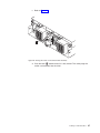
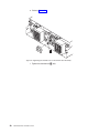
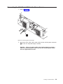
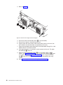
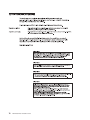
1
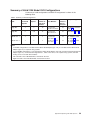
Expandable Storage Plus
2104 Model DU3
Installation Guide
GA33-3311-03
Expandable Storage Plus
2104 Model DU3
Installation Guide
GA33-3311-03
Fourth Edition (June 2003)
This revision supersedes GA33-3311-02. Technical changes are shown by a vertical line to the left of each change.
The following paragraph does not apply to any country where such provisions are inconsistent with local
law:
THIS PUBLICATION IS PRINTED “AS IS” WITHOUT WARRANTY OF ANY KIND, EITHER EXPRESS OR IMPLIED,
INCLUDING, BUT NOT LIMITED TO, THE IMPLIED WARRANTIES OF MERCHANTABILITY OR FITNESS FOR A
PARTICULAR PURPOSE. Some states do not allow disclaimer of express or implied warranties in certain
transactions; therefore, this statement may not apply to you.
This publication could contain technical inaccuracies or typographical errors. Changes are periodically made to the
information herein; these changes will be incorporated in new editions of the publication.
It is possible that this publication may contain reference to, or information about, products (machines and programs),
programming, or services that are not announced in your country. Such references or information must not be
construed to mean that such products, programming, or services will be offered in your country. Any reference to a
licensed program in this publication is not intended to state or imply that you can use only the licensed program
indicated. You can use any functionally equivalent program instead.
© Copyright International Business Machines Corporation 2000, 2003. All rights reserved.
Note to U.S. Government Users – Documentation related to restricted rights – Use, duplication, or disclosure is
subject to restrictions set forth in the GSA ADP Schedule Contract.
Contents
Communications Statements . . . . . . . . . . . . . . .
Federal Communications Commission (FCC) Statement . . . . . .
Japanese Voluntary Control Council for Interference (VCCI) Statement .
Korean Government Ministry of Communication (MOC) Statement . .
New Zealand Compliance Statement . . . . . . . . . . . . .
International Electrotechnical Commission (IEC) Statement . . . . .
Avis de conformité à la réglementation d’Industrie Canada . . . . .
Industry Canada Compliance Statement . . . . . . . . . . . .
United Kingdom Telecommunications Requirements . . . . . . .
European Union (EU) Statement. . . . . . . . . . . . . . .
Radio Protection for Germany. . . . . . . . . . . . . . . .
Taiwan Class A Compliance Statement . . . . . . . . . . . .
.
.
.
.
.
.
.
.
.
.
.
.
.
.
.
.
.
.
.
.
.
.
.
.
.
.
.
.
.
.
.
.
.
.
.
.
. v
. v
. v
. v
. v
. v
. vi
. vi
. vi
. vi
. vi
. vii
Safety Notices . . . . . . . . . . . . . . . . . . . . . . . . . ix
Definitions of Safety Notices . . . . . . . . . . . . . . . . . . . . ix
Safety Notice for Installing, Relocating, or Servicing . . . . . . . . . . . ix
Electrostatic Discharge (ESD) . . . . . . . . . . . . . . . . . . . xi
About This Book . .
Numbering Convention .
Related Publications . .
Trademarks . . . . .
|
|
|
|
|
|
|
|
|
.
.
.
.
.
.
.
.
.
.
.
.
.
.
.
.
.
.
.
.
.
.
.
.
.
.
.
.
.
.
.
.
.
.
.
.
.
.
.
.
.
.
.
.
.
.
.
.
.
.
.
.
.
.
.
.
.
.
.
.
.
.
.
.
.
.
.
.
.
.
.
.
.
.
.
.
.
.
.
.
.
.
.
.
.
.
.
.
.
.
.
.
. 1
. 3
. 4
. 5
. 7
. 12
. 15
. 18
. 29
. 31
. 33
Appendix A. Operating with RISC Systems . . . .
SCSI Service Aids. . . . . . . . . . . . . . .
Identifying 2104s and Disk Drive Modules . . . . . .
AIX . . . . . . . . . . . . . . . . . . .
Linux . . . . . . . . . . . . . . . . . .
Configuring a 2104 to the using system . . . . . . .
AIX . . . . . . . . . . . . . . . . . . .
Linux . . . . . . . . . . . . . . . . . .
Unconfiguring a 2104 from the using system . . . . .
AIX . . . . . . . . . . . . . . . . . . .
Linux . . . . . . . . . . . . . . . . . .
Valid 2104 Model DU3 Configurations . . . . . . .
Summary of Valid 2104 Model DU3 Configurations. .
Single-Bus Mode Configurations . . . . . . . .
Dual-Bus Mode Configurations . . . . . . . . .
Configurations That are Not Valid . . . . . . . . .
Two Adapters in One Using System Connected to One
.
.
.
.
.
.
.
.
.
.
.
.
.
.
.
.
.
.
.
.
.
.
.
.
.
.
.
.
.
.
.
.
.
.
.
.
.
.
.
.
.
.
.
.
.
.
.
.
.
.
.
.
.
.
.
.
.
.
.
.
.
.
.
.
.
.
.
.
.
.
.
.
.
.
.
.
.
.
.
.
.
.
.
.
.
.
.
.
.
.
.
.
.
.
.
.
.
.
.
.
.
.
.
.
.
.
.
.
.
.
.
.
.
.
.
.
.
.
.
.
.
.
.
.
xiii
xiii
xiii
xiii
Installing a 2104 Model DU3 . . . . . . . . . . . . . . . . .
Installing a 2104 Model DU3 into a Rack . . . . . . . . . . . . .
Checking the Items for a 2104 Model DU3 . . . . . . . . . . .
Preparing the Rack (System or Expansion) . . . . . . . . . . .
Removing the Disk Drive Modules and Dummy Disk Drive Modules . .
Installing the 2104 Model DU3 into the Rack . . . . . . . . . .
Reinstalling the Disk Drive Modules and Dummy Disk Drive Modules .
Setting the Options on the 2104 Model DU3 . . . . . . . . . . .
Connecting the 2104 Model DU3 to the Power Source . . . . . . .
Connecting the 2104 to the Using System . . . . . . . . . . . .
Switching On and Testing the 2104 . . . . . . . . . . . . . .
. .
. .
. .
. .
. .
. .
. .
. .
. .
. .
. .
. .
. .
. .
. .
. .
2104
.
.
.
.
.
.
.
.
.
35
35
35
35
35
35
35
35
37
37
37
38
39
40
47
53
53
iii
One Adapter in One Using System Connected to Two 2104s via the SCSI
Interface Cards . . . . . . . . . . . . . . . . . . . . . .
One Adapter in One Using System Connected to 2104s via a Y-Cable (1)
One Adapter in One Using System Connected to 2104s via a Y-Cable (2)
One Dual-Channel Non-RAID Adapter in One Using System Connected to
Two 2104s and Internal Disk Drives . . . . . . . . . . . . . .
One RAID Adapter in Each of Two Using Systems Connected to Two 2104s
Collecting Errors . . . . . . . . . . . . . . . . . . . . . . .
Web Support Pages . . . . . . . . . . . . . . . . . . . . . .
Related Publications . . . . . . . . . . . . . . . . . . . . . .
. 54
55
56
. 57
58
. 59
. 59
. 61
Appendix B. Translated Safety Notices . . . . . . . . . . . . . . . 63
iv
2104 Model DU3 Installation Guide
Communications Statements
The following statements apply to this product. The statements for other products
intended for use with this product appear in their accompanying manuals.
Federal Communications Commission (FCC) Statement
This equipment has been tested and found to comply with the limits for a Class A
digital device, pursuant to Part 15 of the FCC Rules. These limits are designed to
provide reasonable protection against harmful interference when the equipment is
operated in a commercial environment. This equipment generates, uses, and can
radiate radio frequency energy and, if not installed and used in accordance with the
instruction manual, may cause interference to radio communications. Operation of
this equipment in a residential area is likely to cause harmful interference, in which
case the user will be required to correct the interference at his own expense.
Properly shielded and grounded cables and connectors must be used in order to
meet FCC emission limits. Neither the provider nor the manufacturer is responsible
for any radio or television interference caused by using other than recommended
cables and connectors or by unauthorized changes or modifications to this
equipment. Unauthorized changes or modifications could void the user’s authority to
operate the equipment.
This device complies with Part 15 of FCC Rules. Operation is subject to the
following two conditions: (1) this device may not cause harmful interference, and (2)
this device must accept any interference received, including interference that may
cause undesired operation.
Japanese Voluntary Control Council for Interference (VCCI) Statement
This product is a Class A Information Technology Equipment and conforms to the
standards set by the Voluntary Control Council for Interference by Information
Technology Equipment (VCCI). In a domestic environment, this product might cause
radio interference, in which event the user might be required to take adequate
measures.
Korean Government Ministry of Communication (MOC) Statement
Please note that this device has been approved for business purposes with regard
to electromagnetic interference. If you find that this device is not suitable for your
use, you can exchange it for one that is approved for non-business purposes.
New Zealand Compliance Statement
This is a Class A product. In a domestic environment this product might cause radio
interference, in which event the user might be required to take adequate measures.
International Electrotechnical Commission (IEC) Statement
This product has been designed and built to comply with (IEC) Standard 60950.
v
Avis de conformité à la réglementation d’Industrie Canada
Cet appareil numérique de la classe A est conforme à la norme NMB-003 du
Canada.
Industry Canada Compliance Statement
This Class A digital apparatus complies with IECS-003.
United Kingdom Telecommunications Requirements
This apparatus is manufactured to the International Safety Standard EN60950 and
as such is approved in the U.K. under approval number NS/G/1234/J/100003 for
indirect connection to public telecommunications systems in the United Kingdom.
European Union (EU) Statement
This product is in conformity with the protection requirements of EU council directive
89/336/EEC on the approximation of the laws of the Member States relating to
electromagnetic compatibility. Neither the provider nor the manufacturer can accept
responsibility for any failure to satisfy the protection requirements resulting from a
non-recommended modification of the product, including the fitting of option cards
not supplied by the manufacturer.
This product is in conformity with the EU council directive 73/23/EEC on the
approximation of the laws of the Member States relating to electrical equipment
designed for use within certain voltage limits. This conformity is based on
compliance with the following harmonized standard: EN60950.
Radio Protection for Germany
Zulassungsbescheinigung laut dem Deutschen Gesetz über die
elektromagnetische Verträglichkeit von Geräten (EMVG) vom 30. August 1995
(bzw. der EMC EG Richtlinie 89/336):
Dieses Gerät ist berechtigt in Übereinstimmung mit dem Deutschen EMVG das
EG-Konformitätszeichen - CE - zu führen. Verantwortlich für die
Konformitätserklärung nach Paragraph 5 des EMVG ist die:
IBM Deutschland Informationssysteme GmbH, 70548 Stuttgart.
Informationen in Hinsicht EMVG Paragraph 3 Abs. (2) :
Das Gerät erfüllt die Schutzanforderungen nach EN 50082-1 und EN 55022 Klasse A.
EN 55022 Klasse A Geräte müssen mit folgendem Warnhinweis versehen werden:
″Warnung: dies ist eine Einrichtung der Klasse A. Diese Einrichtung kann im
Wohnbereich Funkstörungen verursachen; in diesem Fall kann vom Betreiber
verlangt werden, angemessene Massnahmen durchzuführen und dafür
aufzukommen.″
EN 50082-1 Hinweis:
″Wird dieses Gerät in einer industriellen Umgebung betrieben (wie in EN 50082-2
festgelegt), dann kann es dabei eventuell gestört werden. In solch einem Fall ist der
Abstand bzw. die Abschirmung zu der industriellen Störquelle zu vergrössern.″
vi
2104 Model DU3 Installation Guide
Anmerkung:
Um die Einhaltung des EMVG sicherzustellen sind die Geräte, wie in den
Handbüchern angegeben, zu installieren und zu betreiben.
Taiwan Class A Compliance Statement
Communications Statements
vii
viii
2104 Model DU3 Installation Guide
Safety Notices
Definitions of Safety Notices
A danger notice indicates the presence of a hazard that has the potential of causing
death or serious personal injury.
This book contains no danger notices.
A caution notice indicates the presence of a hazard that has the potential of causing
moderate or minor personal injury.
This book contains caution notices on pages 7, 12, 23, and 26.
An attention notice indicates an action that could cause damage to a program,
device, system, or data.
Safety Notice for Installing, Relocating, or Servicing
Before connecting or removing any cables to or from connectors at the using
system, be sure to follow the steps in the installation or relocation checklist
specified in the Installation and Service Guide, or equivalent, for your using system.
For safety checks when servicing the Expandable Storage Plus, refer to “Service
Inspection Guide” in the Expandable Storage Plus: 2104 Models DU3 and TU3
Service Guide.
ix
x
2104 Model DU3 Installation Guide
Electrostatic Discharge (ESD)
Attention:
When you handle field-replaceable units (FRUs) and other computer parts,
take these precautions to avoid static damage:
v Limit your movement. Movement can cause static electricity to build up
around you.
v Always touch computer parts carefully. Hold adapters and
memory-modules by their edges. Never touch any exposed circuits.
v Prevent people who are not correctly grounded from touching computer
parts.
v Before you install a new part, touch the static-protective package that
contains the part against an unpainted metal part of the 2104 or using
system for at least two seconds. This action reduces static electricity in the
package and in your body.
v Remove the part from its package and, if possible, install it directly into the
2104 without putting the part down. If you need to put the part down, first
place the static-protective package that contained the part onto a smooth,
level surface, then place the part onto the package. Do not place the part
onto any metal surface.
xi
xii
2104 Model DU3 Installation Guide
About This Book
This book provides installation instructions for any person who is required to install
a 2104 Model DU3, which is a rack-mounted Small Computer Systems Interface
(SCSI) disk enclosure.
Important
The installation of this product is a customer responsibility.
Numbering Convention
In this book, one gigabyte (GB) equals 1 000 000 000 bytes.
Related Publications
Publications that are related to the Expandable Storage Plus: 2104 Model DU3:
Expandable Storage Plus: 2104 Models DU3 and TU3 Operator’s Guide,
SA33–3310
Expandable Storage Plus: 2104 Models DU3 and TU3 Service Guide,
GY33–0198
Expandable Storage Plus: 2104 Models DU3 and TU3 Hardware Technical
Information, SA33–3309
For publications that are related to RISC systems, see Appendix A, “Operating with
RISC Systems”, on page 35.
Trademarks
The following items are trademarks of International Business Machines Corporation
in the United States, or other countries, or both:
v AIX
v IBM
v RS/6000
v Eserver
xiii
xiv
2104 Model DU3 Installation Guide
Installing a 2104 Model DU3
Important
The installation of this product is a customer responsibility.
Attention:
Before continuing with any of the actions described in this book, please refer
to Appendix B, “Translated Safety Notices”, on page 63.
These instructions describe how to:
v Install a 2104 Model DU3 into an RS/6000™ or IBM™ ERserver pSeries rack
(system rack or expansion rack)
v Connect the 2104 Model DU3 to a power source
v Connect the 2104 Model DU3 to the using system
v Switch on and test the installation
The instructions assume that:
v The rack has already been set up
v A stabilizer has been correctly attached to the bottom front of the rack to prevent
the rack from tipping forward while the 2104 Model DU3 is being installed into
the rack. (If necessary, see the Installation and Service Guide, or equivalent, for
the rack.)
v You have access to:
– Preinstallation planning information for the system
– 2104 configuration information
If the 2104 Model DU3 has already been installed in the rack:
v Go to “Connecting the 2104 Model DU3 to the Power Source” on page 29 if the
power cables for the 2104 have not been installed.
v Go to “Connecting the 2104 to the Using System” on page 31 if the power cables
for the 2104 have been installed.
Notes:
1. Each rack-mounted 2104 requires an airflow of 1.1 m³ per minute (40 ft³ per
minute). When racks containing many 2104s are to be installed together, the
following requirements must be met to ensure that the 2104s are adequately
cooled:
v The airflow enters at the front of the rack and leaves at the back. To prevent
the air that is leaving the rack from entering the intake of another piece of
equipment, racks should be positioned in alternate rows, back-to-back and
front-to-front.
v The front of racks should be positioned on floor-tile seams, with a full line of
perforated tiles immediately in front of the racks. Each perforated tile should
have an air flow of at least 11.34 m³ per minute (400 ft³ per minute). The
underfloor temperature must not exceed 15°C (60°F).
v Where racks are in rows front-to-front or back-to-back, there should be a gap
of at least 1220 mm (48 in) separating the rows.
v To ensure correct air flow within each rack, the rack filler plates must be
installed in unused positions. Also, all the gaps in the front of the racks must
be sealed, including the gaps between the 2104s.
1
2. The recommended operating temperature is 22°C (72°F) or lower.
2
2104 Model DU3 Installation Guide
Installing a 2104 Model DU3 into a Rack
Installing a 2104 Model DU3 into an RS/6000 or IBMEserver pSeries rack is done
by:
1. Preparing the rack
2. Removing the disk drive modules from the 2104 Model DU3
3. Installing the 2104 Model DU3 into the rack
4. Reinstalling the disk drive modules into the 2104 Model DU3
The procedure that is recommended is described in the next four sections of this
book, but first you need to check whether you have received all the parts required
for your 2104 Model DU3.
Installing a 2104 Model DU3
3
Checking the Items for a 2104 Model DU3
1. Refer to Figure 1.
Figure 1. Items for the 2104 Model DU3
1
2
3
4
2104 Model DU3
Mounting screws (front)
Rail mounting screws
Nut clips
5
6
7
Support rails
Mounting screws (back)
Power cable(s)
Note: If your 2104 Model DU3 has only one fan-and-power-supply assembly,
only one power cable is supplied.
2. Ensure that you have all the items that are shown on the list.
In addition to the items shown there is also a sheet of labels. Use these to label
your disk enclosure (see 4 on page 18).
3. Refer to the Web site described at “Web Support Pages” on page 59 for the
latest microcode and system software levels. When you have completed the
installation, you will be asked to ensure that the latest levels of software and
microcode have been installed.
4
2104 Model DU3 Installation Guide
Preparing the Rack (System or Expansion)
1. Find the two support rails (5 in Figure 1 on page 4) that are supplied with the
2104.
2. The 2104 Model DU3 is three Electronics Industries Association (EIA) units
high. Using the preinstallation planning information, or other relevant
information, determine where you are going to locate the 2104 Model DU3 in
the rack.
Notes:
v If you are installing the 2104 Model DU3 into an empty rack, install it into the
lowest available position so that the rack does not become unstable.
v If you are installing more than one 2104 Model DU3 into the rack, start at the
lowest available position, and work upward.
v You might need to remove the rack power distribution unit before you install
the support rails (see the Installation and Service Guide, or equivalent, for the
rack).
3. Refer to the EIA markings on the rack and decide where you are going to install
the support rails. If appropriate, allow for possible future installation of other disk
enclosures.
Installing a 2104 Model DU3
5
4. Refer to Figure 2.
3
6
1
2
4
4
5
Figure 2. Installing the Support Rails
5. For each support rail:
a. Attach nut clips 2 at the selected holes in the front of the rack. These nut
clips must align with the upper and lower holes in the support rail.
b. Count two holes upward from the upper nut clip, and attach a nut clip 1.
c. At the back of the rack, install two nut clips 3 at the selected holes.
d. Loosen the four adjustment screws 4 so that you can adjust the length of
the support rail.
e. At the front of the rack, locate the support rail so that its mounting lug is
outside the nut clips 2.
f. Insert the rail screws 5 through the holes in the lug and into the nut clips.
g. Partially tighten the screws.
h. At the back of the rack, locate the support rail so that its mounting lug is
outside the nut clips 3.
i. Insert the rail screws 6 through the holes in the lug and into the nut clips.
j. Partially tighten the screws.
k. Check whether the support rail is horizontal (a spirit level might be useful
here). If the rail is not horizontal, relocate it as necessary.
l. Fully tighten the front and back rail screws.
m. Fully tighten the four adjustment screws 4.
6. Go to “Removing the Disk Drive Modules and Dummy Disk Drive Modules” on
page 7.
6
2104 Model DU3 Installation Guide
Removing the Disk Drive Modules and Dummy Disk Drive Modules
CAUTION:
A 2104 Model DU3 weighs up to 38.5 kg (85 lb) with disk drive modules
installed. Do not attempt to lift the 2104 Model DU3 into the rack unless all the
disk drive modules have been removed.
Attention: Disk drive modules are fragile. Handle them with care, and keep them
well away from strong magnetic fields.
1. Refer to Figure 3.
Figure 3. Disk Drive Modules showing position of the Serial Number Label
2. Before you start to remove any modules, make a list of which disk drive
modules are in which slots in the 2104 Model DU3. This action helps you to
reinstall the modules into their correct slots after you have installed the 2104
Model DU3 into the rack.
Disk drive modules have a serial number label 1. This label carries the last 8
to 10 digits of the serial number of the disk drive, and also the disk drive type
(SCSI) and capacity (for example, 18.2 GB).
Note: Each disk drive module also has a SCSI address that is related to its
position in the 2104 Model DU3. Disk drive modules must be reinstalled
into the same slots from which they were removed.
Installing a 2104 Model DU3
7
3. Refer to Figure 4.
Figure 4. Opening the Handle of a Disk Drive Module
4. Press the blue latch 1, and pull the handle 2 fully up. This action pulls the
disk drive module partially out of its slot.
8
2104 Model DU3 Installation Guide
5. Refer to Figure 5.
Figure 5. Removing a Disk Drive Module
6. Grip the handle, and carefully pull out the disk drive module. As the module
comes out, put one hand under its base to prevent it from falling.
Installing a 2104 Model DU3
9
7. Lay the disk drive module on its side as shown in Figure 6. It rests on four blue
supports (not visible in the figure) on the bottom of the disk drive module. This
prevents the disk drive module from falling over and becoming damaged.
Figure 6. Disk Drive Module on its Side for Safe Storage
Note: It is recommended that the removed disk drive modules be kept in the
sequence they were in before they were removed from the 2104 Model DU3.
8. Repeat steps 3 through 7 for each disk drive module. Ensure that you remove
all the disk drive modules from the 2104 Model DU3.
10
2104 Model DU3 Installation Guide
9. You might also want to remove the dummy disk drive modules. A dummy disk
drive module has a simple handle. There is no latch to be pulled upward.
Refer to Figure 7.
Figure 7. Removing a Dummy Disk Drive Module
Installing a 2104 Model DU3
11
Installing the 2104 Model DU3 into the Rack
CAUTION:
v A 2104 Model DU3 weighs up to 38.5 kg (85 lb) with disk drive modules
installed. Do not attempt to lift the 2104 Model DU3 into the rack unless all
the disk drive modules have been removed.
v Do not attempt to lift the 2104 by yourself. Ask another person for aid.
v Do not use the handles of the fan or fan-and-power-supply assemblies to
carry the 2104. These handles are not intended to support the weight of the
2104.
v The stabilizer must be correctly attached to the bottom front of the rack to
prevent the rack from tipping forward while the 2104 Model DU3 is being
installed into the rack. Do not pull out or install any unit if the stabilizer is
not attached to the rack.
Note: If you are going to install the 2104 Model DU3 into a Model T00 or T42 rack,
you must also observe the safety notices for those racks before you start.
You can find the safety notices in the System Installation chapter of the 7014
Model T00 and T42 Rack Installation and Service Guide, SA38-0577, or at
web page:
|
|
http://www-1.ibm.com/servers/eserver/pseries/library/hardware_docs/sa38/380577.pdf
1. If you have not already done so, remove all the disk drive modules from the
2104 Model DU3 (see “Removing the Disk Drive Modules and Dummy Disk
Drive Modules” on page 7).
2. Stand at the front of the rack and, with help from another person, place the
back of the 2104 Model DU3 onto the support rails, then slide the 2104 Model
DU3 into the rack.
12
2104 Model DU3 Installation Guide
3. Refer to Figure 8.
Figure 8. Installing the Front Mounting Screws
4. Install the two front mounting screws 1 and tighten them.
Installing a 2104 Model DU3
13
5. Refer to Figure 9.
Figure 9. Installing the Back Mounting Screws
6. At the back of the rack, install and tighten the two screws 1.
Note: These are the screws identified as 6 in Figure 1 on page 4.
7. Go to “Reinstalling the Disk Drive Modules and Dummy Disk Drive Modules” on
page 15.
14
2104 Model DU3 Installation Guide
Reinstalling the Disk Drive Modules and Dummy Disk Drive Modules
Attention:
v Disk drive modules are fragile. Handle them with care, and keep them well away
from strong magnetic fields.
v Any slot that has no disk drive module installed must contain a dummy disk drive
module. The dummy disk drive module ensures that the correct airflow is
maintained around the disk drive modules in the other slots.
1. Referring to the note that you made about the original locations of the disk
drive modules, reinstall the disk drive modules (in the same sequence that
they were removed) as described in the following steps.
2. Refer to Figure 10.
Figure 10. Reinstalling a Disk Drive Module
3. Ensure that the handle 1 is fully open on the disk drive module that you are
going to install.
4. With one hand giving support to the base of the disk drive module and the
other hand holding the handle 1, insert the disk drive module and push it into
the slot.
When the handle touches the front surface of the enclosure, the module stops.
Note that the disk drive module is not yet fully home.
Installing a 2104 Model DU3
15
5. Refer to Figure 11.
Figure 11. Closing the Handle of a Disk Drive Module
6. While continuing to push the disk drive module into the slot, slowly close the
handle 1 until it stops with a click. This action pushes the module fully home.
7. Verify that the disk drive module that you have just installed is aligned with the
sides of the 2104 and that no gap exists between this module and the modules
that are next to it.
Verify also that the front edge of this disk drive module aligns with the front
edges of the modules that are next to it.
If the disk drive module is not correctly aligned, remove it (see “Removing the
Disk Drive Modules and Dummy Disk Drive Modules” on page 7) and reinstall
it (steps 2 through 6 above).
8. Repeat steps 2 through 7 for each disk drive module.
Attention: Any slot that has no disk drive module installed must contain a
dummy disk drive module. The dummy disk drive module ensures that the
correct airflow is maintained around the disk drive modules in the other slots.
16
2104 Model DU3 Installation Guide
9. Ensure that the 2104 Model DU3 has no empty slots. Install dummy disk drive
modules if necessary.
10. Refer to Figure 12.
Figure 12. Reinstalling a Dummy Disk Drive Module
11. Go to “Connecting the 2104 Model DU3 to the Power Source” on page 29.
Installing a 2104 Model DU3
17
Setting the Options on the 2104 Model DU3
1. Refer to your 2104 configuration information for details of how the options are to
be set.
2. Refer to Figure 13.
Figure 13. Setting the Box ID
3. Rotate the Box ID rotary switch to the ID you have chosen for this 2104 disk
enclosure. You need a small screwdriver to do this.
4. Find the sheet of labels supplied with your 2104. These are numbers 0 through
9. Select the one that represents your setting of the Box ID rotary switch and
attach it to the front of the 2104.
Note: When running the Linux operating system it is recommended that you set
the Box ID switch and attach the Box ID label. Your Linux operating
system may or may not display the Box ID in its system messages. The
Box ID is used when running the standalone AIX Diagnostics CD.
|
|
|
|
18
2104 Model DU3 Installation Guide
5. Now look at the option switches. Refer to Figure 14.
54321
Off
OPTION
SWITCH
On
1
2
3
4
5
Figure 14. Option Switches
6. When the Power Control switch 1 is set to On, the 2104 does not
automatically switch on or off when the using system is switched on or off.
If you want the 2104 to switch on and off automatically with the using system,
ensure that this switch is set to Off.
7. The Drive Autostart switch 2 is set to On at the factory. Do not change this
setting unless the customer requires it to be changed (see Notes).
Similarly, the Delay Motor Start Mode switch 5 is set to Off at the factory. Do
not change this setting unless the customer requires it to be changed (see
Notes).
Installing a 2104 Model DU3
19
Notes:
a. When the Drive Autostart switch 2 is set to On (the default setting), the
motors of the disk drive modules do not start until a Start Motor command
is issued. The timing sequence of startup is under the control of the
using-system software.
When the Drive Autostart switch 2 is set to Off, the disk drive modules are
set to Delay Motor Start mode.
The delay time before motor startup is specified by the disk drive modules.
After power is switched on, the delay time is usually SCSI ID x 12 seconds.
For example, the delay for a disk drive module whose SCSI ID is 2 is 2x12
seconds (24 seconds).
b. The Delay Motor Start Mode switch 5 selects either Delay Motor Start
Mode or Normal Start Mode when the Drive Autostart switch 2 is set to Off
.
When the Delay Motor Start Mode switch 5 is set to On, Delay Motor Start
mode is selected.
The delay time before motor startup is specified for each disk drive module.
After power is switched on, the delay time is usually SCSI ID x 12 seconds.
For example, the delay for a disk drive module whose SCSI ID is 2 is 2x12
seconds (24 seconds).
When the Delay Motor Start Mode switch 5 is set to Off, Normal Start
Mode is selected. Immediately after power is switched on, the motors of the
disk drive modules start.
8. Ensure that the Enable Enclosure Services switch 3 and the Select Enclosure
Services switch 4 are both set to On to allow ANSI SCSI-3 Enclosure
Services (SES) to operate. This applies to both AIX and Linux users. Your Linux
operating system may not support SES but the SES functions are used when
running the standalone AIX Diagnostics CD.
|
|
|
|
|
20
2104 Model DU3 Installation Guide
9. Now you must remove the switch card assembly so that you can check and, if
necessary, change the settings of the internal switches. To remove the switch
card assembly:
a. Refer to Figure 15.
1
Figure 15. Unscrewing the Thumbscrew on the Switch Card Assembly
b. Unscrew the thumbscrew 1.
Installing a 2104 Model DU3
21
c. Refer to Figure 16.
1
Figure 16. Opening the Lever on the Switch Card Assembly
d. Pull the lever 1 upward. This action unplugs the switch card assembly
from the 2104.
22
2104 Model DU3 Installation Guide
e. Refer to Figure 17.
Figure 17. Removing the Switch Card Assembly
f. Pull the switch card assembly out from the 2104.
CAUTION:
Do not insert hands or tools into the space that contained the switch
card assembly.
Installing a 2104 Model DU3
23
10. Refer to Figure 18.
4 3 2 1
Off
On
Figure 18. Switch Card Assembly Internal Switches
|
|
|
|
11. Each disk drive module is identified to the using system by a SCSI address.
This address is related to the slot in which the disk drive module is installed.
The SCSI address switch 1 must always be set to the Off position.
Table 1 shows the SCSI addresses of the disk drive module slots.
|
|
Note: On the 2104 Model DU3, the physical numbers of the disk drive
module slots are always 1 through 14, from left to right.
|
Table 1. SCSI Addresses of Disk Drive Module Slots
|
|
Disk drive
module slot
1
2
3
4
5
6
7
8
9
10
11
12
13
14
|
|
|
SCSI
address
0
1
2
3
4
5
6
8
9
10
11
12
13
14
|
|
|
|
|
Note: If the 2104 is configured for single SCSI bus mode with two SCSI
attachments (for example, SCSI adapters), SCSI addresses 5 and 6
cannot be used. The disk drive module slots with SCSI addresses 5 and
6 (disk drive module slots 6 and 7) must contain dummy disk drive
modules.
|
|
The SCSI enclosure services (SES) use address 15 if the Enable Enclosure
Services switch is set to On.
24
2104 Model DU3 Installation Guide
|
|
Note: Your Linux operating system may not support SES but the SES
functions are used when running the standalone AIX Diagnostic CD.
|
|
|
|
|
|
Attention: The SCSI address of the SCSI attachment that is connected to the
2104 must be different from the addresses of the installed disk drive modules.
When a second SCSI attachment is connected to a 2104, the SCSI address of
that SCSI attachment must be different from the address of the first SCSI
attachment and different from the addresses of the installed disk drive
modules.
12. The 2104 Orientation switch 2 configures the Power and Check lights that
are on the front of the 2104. Ensure that this switch is set to Off so that the
lights are correct for your 2104 Model DU3.
13. The SCSI Bus Split switch 3 controls the SCSI bus configuration of your
2104. When the switch is set to Off, the 2104 is configured in single SCSI bus
mode. When the switch is set to On, the 2104 is configured in dual SCSI bus
(split bus) mode.
|
|
|
|
|
When a 2104 Model DU3 is in dual SCSI bus mode, the SCSI addresses of
one SCSI bus are 0 through 6, from left to center, and the SCSI addresses of
the other SCSI bus are 8 through 14, from center to right.
Refer to the 2104 configuration information, and set the SCSI Bus Split switch
3 as required.
14. Switch 4 is reserved. Ensure that is it set to Off.
Installing a 2104 Model DU3
25
15. Reinstall the switch card assembly:
a. Refer to Figure 19.
Figure 19. Inserting the Switch Card Assembly
b. Insert the switch card assembly into the 2104. Push the assembly in until it
stops.
CAUTION:
As you push the assembly fully home, the lever automatically moves
toward its closed position. Ensure that your fingers do not become
pinched between the lever and the assembly.
26
2104 Model DU3 Installation Guide
c. Refer to Figure 20.
1
Figure 20. Closing the Lever on the Switch Card Assembly
d. Push the lever 1 downward until it is fully closed. This action plugs the
switch card assembly into the 2104 .
Installing a 2104 Model DU3
27
e. Refer to Figure 21.
1
Figure 21. Tightening the Thumbscrew on the Switch Card Assembly
f. Tighten the thumbscrew 1 fully.
28
2104 Model DU3 Installation Guide
Connecting the 2104 Model DU3 to the Power Source
1. Refer to Figure 22.
Figure 22. Connecting the Power Plugs
2. At the back of the 2104, plug a power cable into the mainline power connector
1 on each fan-and-power-supply assembly.
Attention: Never use power cables from another drawer to connect a
2104 to the mainline power outlet. Use only the shielded power cables
that are supplied with the 2104.
Installing a 2104 Model DU3
29
3. Refer to Figure 23.
Figure 23. Check Power Supply Switch and Lights
4. Ensure that the DC On/Standby switch 1 is set to Standby.
5. Ensure that all power is removed from the rack.
6. Plug the other end of the power cable into the power source in the rack (see
the Installation and Service Guide, or equivalent, for the rack).
7. Perform the grounding checks described in the Expandable Storage Plus: 2104
Models DU3 and TU3 Service Guide.
8. If the grounding check is satisfactory, switch on power to the rack. The green
AC PWR light 4 comes on.
9. Switch on the DC On/Standby switch 1 on each power supply. If option
switch 1 (see Figure 14 on page 19) is on, the green DC PWR light 3 comes
on. If option switch 1 (see Figure 14 on page 19) is off, the green DC PWR
light 3 stays off. It will come on when the 2104 is connected to the using
system.
10. Go to “Connecting the 2104 to the Using System” on page 31.
30
2104 Model DU3 Installation Guide
Connecting the 2104 to the Using System
1. Referring to your preinstallation planning information or 2104 configuration
information, check how the 2104 is to be connected to the using system. Verify
your configuration by referring to “Valid 2104 Model DU3 Configurations” on
page 38.
2. Attach identification labels to the external SCSI signal cables (see the
appropriate Adapters, Devices and Cables Information manual for details).
3. Refer to Figure 24.
Figure 24. Plug in the SCSI Signal Cable
|
|
|
|
|
|
4. Plug the SCSI signal cables into the connectors 1 on the SCSI interface
cards.
Note: Each SCSI interface card can be attached to only one using system. A
2104 that has one SCSI interface card can be attached to only one using
system. A 2104 that has two SCSI interface cards can be attached to two
using systems running AIX. No SCSI terminators are needed.
5. Tighten the retaining screws 2. You might need a small screwdriver to do this.
DO NOT USE A POWER-DRIVEN SCREWDRIVER.
6. Ensure that all signal cables are correctly connected. An incorrect connection
can prevent the 2104 from becoming ready.
Installing a 2104 Model DU3
31
Figure 25. Back of Fully Configured 2104 Model DU3 After Connection to the Using System
32
2104 Model DU3 Installation Guide
Switching On and Testing the 2104
1. If the power to the using system is switched off, switch it on.
2. Refer to Figure 26.
Figure 26. Checking the Lights
The 2104 has two lights. The green Power light 1 comes on and stays on.
The amber Check light 2 comes on for approximately two seconds and goes
off.
Each disk drive module has two lights. The green Activity light 3 comes on for
approximately two seconds when power is first supplied to the disk drive; it then
goes off. The amber Check light 4 then comes on for approximately two
seconds and then goes off.
Note: Dummy disk drive modules have no lights.
Configuration is complete when the lights on the 2104, and its installed disk
drive modules, are as described here (refer to Figure 26):
2104 Power light 1: On
2104 Check light 2: Off
Activity light 3 on each installed disk drive module: Off
Check light 4 on each installed disk drive module: Off
If the lights are correct:
a. Refer to the Web site described at “Web Support Pages” on page 59 for the
latest microcode and system software levels. Ensure that the using-system
software is at the correct level for the 2104, and that the correct level of
microcode for the disk drive modules has been loaded.
b. Go to Appendix A, “Operating with RISC Systems”, on page 35, which gives
information about how to configure your 2104 to the using system, what
service aids are available, and how to collect statistics during the operation
of your 2104.
Installing a 2104 Model DU3
33
If the lights are not as described here, refer to the Expandable Storage Plus:
2104 Models DU3 and TU3 Service Guide, for help in identifying the cause of
this fault.
34
2104 Model DU3 Installation Guide
Appendix A. Operating with RISC Systems
This appendix gives advice for operating an RS/6000 or IBM EserverpSeries
computer to which one or more Expandable Storage Plus 2104 Model DU3 is
attached.
SCSI Service Aids
Service aids are available on the using system to help you service the 2104 Model
DU3. Service aids described in the Expandable Storage Plus: 2104 Models DU3
and TU3 Service Guide are:
v
v
v
v
Format Media
Certify Media
SCSI Device Identification and Removal
Download Microcode
|
Identifying 2104s and Disk Drive Modules
|
AIX
|
|
|
|
When running AIX, you can identify an Expandable Storage Plus 2104 Model DU3
and the disk drive modules installed in it either by the location code contained in
system messages that refer to that unit, or by using the SCSI Device Identification
and Removal service aid.
|
|
See “Location Codes” in the operator guide for your system for general information
about location codes.
|
Linux
|
|
|
|
When running Linux, you can identify an Expandable Storage Plus 2104 Model DU3
and the disk drive modules installed in it by using the “List Configuration” command.
Consult your Linux operating system documentation for information in how to use
this command.
|
|
|
|
Note: Refer to the 2104 Interoperability Matrix link located at
http://www.storage.ibm.com/disk/expplus/supserver.htm to learn which
versions of AIX or Linux are supported for the Expandable Storage Plus
family of products.
|
|
Configuring a 2104 to the using system
|
AIX
|
|
When running AIX, use the cfgmgr command to configure or reconfigure a 2104 to
the using system.
|
Note: This command might not be valid for your RAID adapter.
|
|
|
|
Linux
Refer to the 2104 Interoperability Matrix link located at
http://www.storage.ibm.com/disk/expplus/supserver.htm to learn which versions of
AIX or Linux are supported for the Expandable Storage Plus family of products.
35
When running Linux, the 2104 and its disk drive modules will be configured to the
system the next time the Linux operating system is rebooted. You can then use the
appropriate Linux utilities to partition your drives.
|
|
|
36
2104 Model DU3 Installation Guide
|
Unconfiguring a 2104 from the using system
|
AIX
|
To remove a 2104 from the using system running AIX, use the following command:
|
rmdev -l [enclosurenumber] -d
|
|
where [enclosurenumber] is the enclosure device that was generated by the cfgmgr
command (for example, [ses0], [ses1], [ses2]).
|
Remove the ses_healthcheck job from the system cron table.
|
|
|
|
Linux
To remove a 2104 from the using system running Linux, bring the Linux system
down, power off, and disconnect the 2104, and then reboot the Linux operating
system.
Appendix A. Operating with RISC Systems
37
Valid 2104 Model DU3 Configurations
Only point-to-point connections are allowed between the SCSI interface cards in a
2104 and the SCSI adapter or integrated SCSI port in a using system.
A 2104 Model DU3 that has only one SCSI interface card can be attached to only
one SCSI adapter or integrated SCSI port. A 2104 Model DU3 that has two SCSI
interface cards can be attached to two SCSI adapters or integrated SCSI ports.
When an internal connector on the adapter is used, the corresponding external
connector must not be used to connect to a 2104 Model DU3.
A 2104 Model DU3 can be configured to support either a single SCSI bus or a dual
SCSI bus. The setting of the SCSI Bus Split switch on the switch card in the 2104
Model DU3 defines which configuration is to be used.
An RS/6000 or IBM Eserver pSeries computer uses one of the following SCSI
adapters to connect to the 2104:
v PCI SCSI-2 Single-Ended Fast/Wide Adapter (type 4-A, feature 6208)
– This adapter has one external SCSI connector and one internal SCSI
connector. Both connectors are connected to the same shared SCSI channel.
v PCI Single-Ended Ultra SCSI Adapter (type 4-K, feature 6206)
– This adapter has one external SCSI connector and one internal SCSI
connector. The two connectors are connected to the same shared SCSI
channel.
|
v PCI Dual-Channel Ultra2 SCSI Adapter (type 4-R, feature 6205)
– This dual-channel adapter has two external SCSI connectors and two internal
SCSI connectors. Each pair, consisting of one external and one internal
connector, is connected to a separate SCSI channel.
v PCI Dual-Channel Ultra3 SCSI Adapter (type 4-Y, feature 6203)
|
|
Note: Feature code 6203 is the only adapter that supports the attachment of the
2104 to a Linux for pSeries operating system.
|
|
|
– This dual-channel adapter has two external SCSI connectors and two internal
SCSI connectors. Each pair, consisting of one external and one internal
connector, is connected to a separate SCSI channel.
v PCI 3-Channel Ultra2 SCSI RAID Adapter (type 4-T feature 2494)
– This 3-Channel adapter has two external SCSI connectors and one internal
SCSI connector. Each connector is connected to a separate SCSI channel.
v PCI 4-Channel Ultra3 SCSI RAID Adapter (type 4-X, feature 2498)
– This 4-Channel adapter has four external SCSI connectors and two internal
SCSI connectors. The Channel 1 and Channel 2 external connectors share
the same SCSI bus as the corresponding Channel 1 and Channel 2 internal
connectors. The Channel 3 and Channel 4 external connectors have their own
non-shared SCSI bus.
An RS6000 or IBM Eserver pSeries computer running Linux for pSeries uses the
PCI Dual-Channel Ultra3 SCSI Adapter (Feature Code 6203, type 4–Y) to connect
to the 2104 Model DU3 or 2104 Model TU3.
|
|
|
38
2104 Model DU3 Installation Guide
Summary of Valid 2104 Model DU3 Configurations
A summary of valid configurations and SCSI ID assignments is shown in the
following table:
Table 2. Summary of Valid Configurations
SCSI Bus
Mode
Number of
Connected
Adapters
SCSI IDs of
Adapters
Maximum
Number of
Disk Drive
Modules
SCSI IDs of Disk
Drive Modules
SCSI ID of
Enclosure
Services
Processor
Adapters Supported
Single Bus
1
7
14
0,1,2,3,4,5,6,
8,9,10,11,12,13,14
15
All adapters listed on
page 38.
Single Bus
2
5, 6
12
0,1,2,3,4,8,9,
10,11,12,13,14
15
See Notes 1 and 2.
Dual Bus
v SCSI Bus 1
1
7
7
15
v SCSI Bus 2
1
7
7
0,1,2,3,4,5,6
(See Note 3.)
8,9,10,11,12,13,14
(See Note 4.)
All
on
All
on
15
adapters listed
page 38.
adapters listed
page 38.
Notes:
1. In HACMP configurations: PCI Dual-Channel Ultra2 SCSI Adapter (type 4-R), or PCI Dual-Channel Ultra3 SCSI
Adapter (type 4-Y) in separate using systems
2. In non-HACMP configurations : PCI Dual-Channel Ultra2 SCSI Adapter (type 4-R), PCI Dual-Channel Ultra3 SCSI
Adapter (type 4-Y), or Ultra2 SCSI Integrated Port , either in the same, or in separate using systems, but not
sharing access to the disk drive modules.
3. Left hand half of the 2104 Model DU3, viewed from the front
4. Right hand half of the 2104 Model DU3, viewed from the front
Appendix A. Operating with RISC Systems
39
Single-Bus Mode Configurations
For a single-bus mode configuration, the SCSI Bus Split switch on the switch card
of a 2104 Model DU3 must be set to Off.
Each 2104 Model DU3 can be connected to one external SCSI connector on a
SCSI adapter card, or to one integrated SCSI port, in a using system. If an adapter
card has four external SCSI connectors, it can be connected to up to four 2104s
(Model DU3 or TU3).
For High Availability Cluster Multi-Processing (HACMP) configurations, the two
SCSI interface cards in a 2104 are connected either to external SCSI connectors on
adapter cards, or to integrated Ultra2 SCSI ports, in two different using systems.
The adapter cards must be a PCI Dual-Channel Ultra2 SCSI Adapters (Type 4-R,
feature 6205) or a PCI Dual-Channel Ultra3 SCSI Adapter (type 4-Y, feature 6203).
For non-HACMP configurations, the SCSI interface cards in a 2104 can be
connected either to an external SCSI connector on an adapter card, or to an Ultra2
SCSI integrated port, in a using system. Each adapter card must be a PCI
Dual-Channel Ultra2 SCSI Adapters (Type 4-R, feature 6205) or a PCI
Dual-Channel Ultra3 SCSI Adapter (type 4-Y, feature 6203). The adapters can be in
the same using system or in two different using systems. However, they must not
share access to the disk drives in the 2104.
40
2104 Model DU3 Installation Guide
One Adapter in One Using System Connected to One 2104 Model
DU3
1
1
2104 Subsystem
2
Using System
Figure 27. One Adapter in One Using System connected to One 2104 (Single-Bus Mode)
1
SCSI interface card
Note: The second SCSI interface card that is in the 2104 is optional.
2
SCSI adapter of one of these types:
v PCI SCSI-2 Single-Ended Fast/Wide Adapter (type 4-A, feature 6208)
v PCI Single-Ended Ultra SCSI Adapter (type 4-K, feature 6206)
v PCI Dual-Channel Ultra2 SCSI Adapter (type 4-R, feature 6205)
v PCI Dual-Channel Ultra3 SCSI Adapter (type 4-Y, feature 6203)
v PCI 3-Channel Ultra2 SCSI RAID Adapter (type 4-T feature 2494)
v PCI 4-Channel Ultra3 SCSI RAID Adapter (type 4-X, feature 2498)
Note: The 2104 can be connected to an integrated SCSI port instead of to one of
these adapters.
|
|
|
Attention: An RS6000 or IBM Eserver pSeries computer running Linux for
pSeries uses the PCI Dual-Channel Ultra3 SCSI Adapter (Feature Code 6203, Type
4–Y) to connect to the 2104 Model DU3 or 2104 Model TU3.
Attention: The SCSI address of the adapter that is connected to the 2104 must be
different from the addresses of the installed disk drive modules.
Appendix A. Operating with RISC Systems
41
Two Adapters in One Using System Connected to Two 2104s
(Model DU3)
1
1
2
2104 Subsystem
2
1
1
Using System
2104 Subsystem
Figure 28. Two Adapters in One Using System Connected to Two 2104s (Single-Bus Mode)
1
SCSI interface card
Note: The second SCSI interface card that is in the 2104 is optional.
2
SCSI adapter of one of these types:
v PCI SCSI-2 Single-Ended Fast/Wide Adapter (type 4-A, feature 6208)
v PCI Single-Ended Ultra SCSI Adapter (type 4-K, feature 6206)
v PCI Dual-Channel Ultra2 SCSI Adapter (type 4-R, feature 6205)
v PCI Dual-Channel Ultra3 SCSI Adapter (type 4-Y, feature 6203)
v PCI 3-Channel Ultra2 SCSI RAID Adapter (type 4-T feature 2494)
v PCI 4-Channel Ultra3 SCSI RAID Adapter (type 4-X, feature 2498)
Note: The 2104 can be connected to an integrated SCSI port instead of to one of
these adapters.
Attention: This 2104 configuration is supported on the Linux for pSeries operating
system when attached to the host with the PCI Dual-Channel Ultra3 SCSI Adapter
(type 4–Y, feature 6203).
|
|
|
Attention: The SCSI address of the adapter that is connected to the 2104 must be
different from the addresses of the installed disk drive modules.
42
2104 Model DU3 Installation Guide
One Adapter in Each of Two Using Systems Connected to Two
2104s (Model DU3)
1
1
2
Maximum of 12
disk drive modules
2104 Subsystem
1
1
Using System
2
Maximum of 12
disk drive modules
2104 Subsystem
Using System
Figure 29. One Adapter in Each of Two Using Systems Connected to Two 2104s (Single-Bus
Mode)
1
SCSI interface card
2
For HACMP configurations in standby and mutual takeover mode:
v PCI Dual-Channel Ultra2 SCSI Adapter (type 4-R, feature 6205)
The two adapters must not be in the same using system.
v PCI Dual-Channel Ultra3 SCSI Adapter (type 4-Y, feature 6203)
The two adapters must not be in the same using system.
The adapters must be in two separate using systems.
For non-HACMP configurations, the connections can be to either two different using
systems or to the same using system, but disk drive modules must not be shared:
v PCI Dual-Channel Ultra2 SCSI Adapter (type 4-R, feature 6205)
v PCI Dual-Channel Ultra3 SCSI Adapter (type 4-Y, feature 6203)
v Ultra2 SCSI Integrated port
|
Attention: This 2104 configuration is not supported on the Linux operating system.
Attention: The SCSI address of the adapter that is connected to the 2104 must be
different from the addresses of the installed disk drive modules. When a second
adapter is connected to a 2104, the SCSI address of that adapter must be different
from the address of the first adapter and the addresses of the disk drive modules
installed in the 2104.
In each 2104, slots 6 and 7 (SCSI addresses 5 and 6) must contain dummy disk
drive modules. Each 2104 can contain no more than 12 disk drive modules.
Appendix A. Operating with RISC Systems
43
One Adapter in One Using System Connected to Two 2104s
(Model DU3)
1
1
2104 Subsystem
2
1
1
Using System
2104 Subsystem
Figure 30. One Adapter in One Using System Connected to Two 2104s - Single-Bus Mode
1
SCSI interface card
Note: The second SCSI interface card that is in the 2104 is optional.
2
SCSI adapter of one of these types:
v PCI SCSI-2 Single-Ended Fast/Wide Adapter (type 4-A, feature 6208)
v PCI Single-Ended Ultra SCSI Adapter (type 4-K, feature 6206)
v PCI Dual-Channel Ultra2 SCSI Adapter (type 4-R, feature 6205)
v PCI Dual-Channel Ultra3 SCSI Adapter (type 4-Y, feature 6203)
v PCI 3-Channel Ultra2 SCSI RAID Adapter (type 4-T feature 2494)
v PCI 4-Channel Ultra3 SCSI RAID Adapter (type 4-X, feature 2498)
Note: The 2104 can be connected to an integrated SCSI port instead of to one of
these adapters.
Attention: This 2104 configuration is supported on the Linux for pSeries operating
system when attached to the host with the PCI Dual-Channel Ultra3 SCSI Adapter
(type 4–Y, feature 6203).
|
|
|
Attention: The SCSI address of the adapter that is connected to the 2104 must be
different from the addresses of the installed disk drive modules.
Note: These configurations are valid with or without an additional integrated port.
44
2104 Model DU3 Installation Guide
One Adapter in One Using System Connected to Two 2104s
(Model DU3) and an Internal RAID Array
1
1
3
2104 Subsystem
2
1
1
Using System
2104 Subsystem
Figure 31. One Adapter, One Using System with Internal RAID Array, and Two 2104s
(Single-Bus Mode)
1
SCSI interface card
Note: The second SCSI interface card that is in the 2104 is optional.
2
SCSI adapter of one of these types:
v PCI 3-Channel Ultra2 SCSI RAID Adapter (type 4-T, feature 2494)
v PCI 4-Channel Ultra3 SCSI RAID Adapter (type 4-X, feature 2498)
3
|
Internal RAID array
Attention: This 2104 configuration is not supported on the Linux operating system.
Attention:
v The SCSI address of the adapter that is connected to the 2104 must be different
from the addresses of the installed disk drive modules.
v The external connectors of the SCSI RAID adapter must not share a SCSI bus
with the internal RAID array.
Appendix A. Operating with RISC Systems
45
One Adapter in Each of Two Using Systems Connected to One
2104 Model DU3
1
1
2
Maximum of 12
disk drive modules
2104 Subsystem
Using System
2
Using System
Figure 32. One Adapter in Each of Two Using Systems Connected to One 2104 Model DU3
(Single-Bus Mode)
1
SCSI interface card
2
For HACMP configurations in standby or mutual takeover mode:
v PCI Dual-Channel Ultra2 SCSI Adapter (type 4-R, feature 6205)
The two adapters must not be in the same using system.
v PCI Dual-Channel Ultra3 SCSI Adapter (type 4-Y, feature 6203)
The two adapters must not be in the same using system.
Note:
For non-HACMP configurations:
v PCI Dual-Channel Ultra2 SCSI Adapter (type 4-R, feature 6205)
v PCI Dual-Channel Ultra3 SCSI Adapter (type 4-Y, feature 6203)
v Ultra2 SCSI Integrated Port
Note: In non-HACMP configurations, connections can be made to two separate
using systems, or to the same using system. Connection can be to an Ultra2 SCSI
integrated port or to an Ultra2 SCSI connector on the SCSI adapters listed. Access
to the disks in the 2104 cannot be shared.
Attention: This 2104 configuration is not supported on the Linux operating system.
|
Attention:
v The SCSI address of the adapter that is connected to the 2104 must be different
from the addresses of the installed disk drive modules. When a second adapter
is connected to a 2104, the SCSI address of that adapter must be different from
the address of the first adapter and the addresses of the installed disk drive
modules.
v In each 2104, slots 6 and 7 (SCSI addresses 5 and 6) must contain dummy disk
drive modules.
v Each 2104 can contain no more than 12 disk drive modules.
46
2104 Model DU3 Installation Guide
Dual-Bus Mode Configurations
For a dual-bus mode configuration, the SCSI Bus Split switches on the switch card
of a 2104 Model DU3 must be set to On.
Each 2104 Model DU3 in the configuration is connected either to one external SCSI
connector on an adapter card, or to an integrated SCSI port. If an adapter card has
four external SCSI connectors, it can be connected to up to four 2104s (Model
DU3).
The external SCSI connectors can be either on the same adapter card, or on two
separate adapter cards. If the connectors are on two separate adapter cards, these
adapter cards can be either both be in the same using system or be in two
separate using systems.
Appendix A. Operating with RISC Systems
47
Two Adapters in One Non-HACMP Using System Connected to
One 2104 Model DU3
2
1
1
2
Using System
2104 Subsystem
Figure 33. Two Adapters in One Non-HACMP Using System Connected to One 2104
(Dual-Bus Mode)
1
SCSI interface card
2
SCSI or SCSI RAID adapter of one of these types:
v PCI SCSI-2 Single-Ended Fast/Wide Adapter (type 4-A, feature 6208)
v PCI Single-Ended Ultra SCSI Adapter (type 4-K, feature 6206)
v PCI Dual-Channel Ultra2 SCSI Adapter (type 4-R, feature 6205)
v PCI Dual-Channel Ultra3 SCSI Adapter (type 4-Y, feature 6203)
v PCI 3-Channel Ultra2 SCSI RAID Adapter (type 4-T feature 2494)
v PCI 4-Channel Ultra3 SCSI RAID Adapter (type 4-X, feature 2498)
Note: Connection can be to an integrated SCSI port instead of to a SCSI connector
on one of the listed SCSI adapters
Attention: This 2104 configuration is supported on the Linux for pSeries operating
system when attached to the host with the PCI Dual-Channel Ultra3 SCSI Adapter
(type 4–Y, feature 6203).
|
|
|
Attention: The SCSI addresses of the adapters that are connected to the 2104
must be different from each other and from the addresses of the installed disk drive
modules.
Note: A similar configuration that has one adapter with two external SCSI
connectors, instead of the two single-connector SCSI adapters, is also a
valid configuration.
48
2104 Model DU3 Installation Guide
Three Adapters in Two Non-HACMP Using Systems Connected to
Two 2104 Model DU3s
2
1
1
2
2104 Subsystem
Using System
1
1
2104 Subsystem
2
Using System
Figure 34. Three Adapters in Two Non-HACMP Using Systems Connected to Two 2104
Model DU3s (Dual-Bus Mode)
1
SCSI interface card
2
SCSI or SCSI RAID adapter of one of these types:
v PCI SCSI-2 Single-Ended Fast/Wide Adapter (type 4-A, feature 6208)
v PCI Single-Ended Ultra SCSI Adapter (type 4-K, feature 6206)
v PCI Dual-Channel Ultra2 SCSI Adapter (type 4-R, feature 6205)
v PCI Dual-Channel Ultra3 SCSI Adapter (type 4-Y, feature 6203)
v PCI 3-Channel Ultra2 SCSI RAID Adapter (type 4-T feature 2494)
v PCI 4-Channel Ultra3 SCSI RAID Adapter (type 4-X, feature 2498)
Note: Connection can be to an integrated SCSI port instead of to a SCSI connector
on one of the listed SCSI adapters
|
|
|
Attention: This 2104 configuration is supported on the Linux for pSeries operating
system when attached to the host with the PCI Dual-Channel Ultra3 SCSI Adapter
(type 4–Y, feature 6203).
Attention: The SCSI address of the adapter that is connected to the 2104 must be
different from the addresses of the installed disk drive modules. When a second
adapter is connected to a 2104, the SCSI address of that adapter must be different
from the address of the first adapter and the addresses of the installed disk drive
modules.
Note: A similar valid configuration can have two adapters, each with one external
SCSI connector, instead of the adapter with two external SCSI connectors.
Appendix A. Operating with RISC Systems
49
One Adapter in One Non-HACMP Using System Connected to
One 2104 Model DU3 and an Internal RAID Array
3
1
1
2
2104 Subsystem
Using System
Figure 35. One Adapter in One Non-HACMP Using System Connected to One 2104 Model
DU3 and an Internal RAID Array (Dual-Bus Mode)
Note: This configuration is not supported for Linux systems.
|
1
SCSI interface card
2
SCSI adapter of one of these types:
v PCI 3-Channel Ultra2 SCSI RAID Adapter (type 4-T feature 2494)
v PCI 4-Channel Ultra3 SCSI RAID Adapter (type 4-X, feature 2498)
3
Internal RAID array
Attention: This 2104 configuration is not supported on the Linux for pSeries
operating system.
|
|
Attention: The SCSI address of the adapter that is connected to the 2104 must be
different from the addresses of the installed disk drive modules.
50
2104 Model DU3 Installation Guide
One Adapter in Each of Two Non-HACMP Using Systems
Connected to One 2104 Model DU3
1
1
2104 Subsystem
2
Using System
2
Using System
Figure 36. One Adapter in Each of Two Non-HACMP Using Systems Connected to One 2104
Model DU3 (Dual-Bus Mode)
1
SCSI interface card
2
SCSI or SCSI RAID adapter of one of these types:
v PCI SCSI-2 Single-Ended Fast/Wide Adapter (type 4-A, feature 6208)
v PCI Single-Ended Ultra SCSI Adapter (type 4-K, feature 6206)
v PCI Dual-Channel Ultra2 SCSI Adapter (type 4-R, feature 6205)
v PCI Dual-Channel Ultra3 SCSI Adapter (type 4-Y, feature 6203)
v PCI 3-Channel Ultra2 SCSI RAID Adapter (type 4-T feature 2494)
v PCI 4-Channel Ultra3 SCSI RAID Adapter (type 4-X, feature 2498)
Note: Connection can be to an integrated SCSI port instead of to a SCSI connector
on one of the listed SCSI adapters
|
|
|
Attention: This 2104 configuration is supported on the Linux for pSeries operating
system when attached to the host with the PCI Dual-Channel Ultra3 SCSI Adapter
(type 4–Y, feature 6203).
Attention: The SCSI address of the adapter that is connected to the 2104 must be
different from the addresses of the installed disk drive modules. When a second
adapter is connected to a 2104, the SCSI address of that adapter must be different
from the address of the first adapter and the addresses of the installed disk drive
modules.
Appendix A. Operating with RISC Systems
51
One RAID Adapter in Each of Two Non-HACMP Using Systems
Connected to Two 2104s (Model DU3)
3
1
1
2
2104 Subsystem
Using System
3
1
1
2
2104 Subsystem
Using System
Figure 37. One RAID Adapter in Each of Two Non-HACMP Using Systems Connected to Two
2104s (Dual-Bus Mode)
Note: This configuration is not supported for Linux systems.
|
1
SCSI interface card
2
SCSI RAID adapter of one of these types:
v PCI 3-Channel Ultra2 SCSI RAID Adapter (type 4-T feature 2494)
v PCI 4-Channel Ultra3 SCSI RAID Adapter (type 4-X, feature 2498)
Attention: This 2104 configuration is not supported on the Linux operating system.
|
Attention:
v The SCSI address of the adapter that is connected to the 2104 must be different
from the addresses of the installed disk drive modules.
v The external connectors on the SCSI RAID adapter cards and the internal RAID
connector must not share a SCSI bus.
52
2104 Model DU3 Installation Guide
Configurations That are Not Valid
This section gives some examples of configurations that are not valid.
Two Adapters in One Using System Connected to One 2104
X
2
1
1
2
2104 Subsystem
Using System
Figure 38. Two Adapters in One Using System Connected to One 2104 (Single-Bus Mode).
This configuration is not valid.
1
SCSI interface card
2
SCSI adapter. This configuration is not valid for any type of adapter.
Note: This configuration is not valid when the 2104 is configured in single-bus
mode, but is valid when the 2104 is configured in dual-bus mode. See page
48.
Appendix A. Operating with RISC Systems
53
One Adapter in One Using System Connected to Two 2104s via the
SCSI Interface Cards
1
X
1
2104 Subsystem
1
2
Using System
1
2104 Subsystem
Figure 39. One Adapter in One Using System Connected to Two 2104s via the SCSI
Interface Cards. This configuration is not valid.
54
1
SCSI interface card
2
SCSI adapter. This configuration is not valid for any type of adapter.
2104 Model DU3 Installation Guide
One Adapter in One Using System Connected to 2104s via a Y-Cable
(1)
3
1
X
1
2104 Subsystem
1
2
Using System
1
2104 Subsystem
Figure 40. One Adapter in One Using System Connected to 2104s via a Y-Cable (1). This
configuration is not valid.
1
SCSI interface card
2
SCSI adapter. This configuration is not valid for any type of adapter.
3
Y-cable. Not supported for any type of adapter that is used with the 2104.
Appendix A. Operating with RISC Systems
55
One Adapter in One Using System Connected to 2104s via a Y-Cable
(2)
1
X
1
3
2104 Subsystem
1
2
Using System
1
2104 Subsystem
Figure 41. One Adapter in One Using System Connected to 2104s via a Y-Cable (2). This
configuration is not valid.
56
1
SCSI interface card
2
SCSI adapter. This configuration is not valid for any type of adapter.
3
Y-cable. Not supported for any type of adapter that is used with the 2104.
2104 Model DU3 Installation Guide
One Dual-Channel Non-RAID Adapter in One Using System Connected
to Two 2104s and Internal Disk Drives
1
X
1
3
3
2104 Subsystem
2
1
1
Using System
2104 Subsystem
Figure 42. One Dual-Channel Non-RAID Adapter in One Using System Connected to Two
2104s and Internal Disk Drives. This configuration is not valid.
1
SCSI interface card
2
PCI Dual-Channel Ultra2 SCSI Adapter (type 4-R, feature 6205) or PCI
Dual-Channel Ultra3 SCSI Adapter (type 4-Y, feature 6203). This configuration is not
valid on this adapter because two internal and two external attachments that are on
the same SCSI bus exceed the capacity of the adapter.
3
Internal disk drives.
Appendix A. Operating with RISC Systems
57
One RAID Adapter in Each of Two Using Systems Connected to Two
2104s
1
X
1
3
2
2104 Subsystem
Using System
1
1
3
2104 Subsystem
2
Using System
Figure 43. One RAID Adapter in Each of Two Using Systems Connected to Two 2104s. This
configuration is not valid.
58
1
SCSI interface card
2
This configuration is not valid for RAID adapters, including the PCI 3-Channel Ultra2
SCSI RAID Adapter (type 4-T, feature 2494) because it cannot use high-availability
cluster multiprogramming (HACMP).
3
Internal RAID disk drive array
2104 Model DU3 Installation Guide
Collecting Errors
|
|
Attention: The following procedure is for AIX operating systems only and does not
apply to Linux operating systems.
To enable the collection of 2104 disk enclosure errors, add this cron job SES
Healthcheck to the system cron table.
Note: Root permissions will be required to perform this update.
Edit the system crons with the crontab -e command. At the bottom of the file, enter:
15 * * * * /usr/lpp/diagnostics/bin/run_ses_healthcheck 1>/dev/null 2>/dev/null
|
For additional details of the crontab command, go to the following Web page:
|
http://publib16.boulder.ibm.com/pseries/en_US/cmds/aixcmds1/crontab.htm
This cron runs at 15 minutes after each hour, and sends mail to the ″root user″ with
details of any errors that are present in the enclosure. It also presents a console
message indicating which enclosure has a problem.
The cron requires a script. To create this script, generate a file named
run_ses_healthcheck in directory /usr/lpp/diagnostics/bin. The contents of the file
must be:
#!/bin/ksh
#Name: run_ses_healthcheck
#Location: /usr/lpp/diagnostics/bin
#Function: SCSI SES hourly healthcheck
for i in `lsdev -Cc container -t ses -s scsi -F name -S available`
do
diag -cd $i > /dev/null
if [ $? -ne 0 ]
then
/usr/lpp/diagnostics/bin/diagrpt -o > /tmp/ses.health.output
# you may want to process the output prior to placing it in
# a file.
# To notify the user of the error, a sample mail instruction is shown
# below.
mail -s ’2104 Health Check’ root < /tmp/ses.health.output
rm /tmp/ses.health.output
fi
done
Note: Although, because of page width, the final line of the contents is shown here
split between two lines, you must enter it all on one line.
Give the following command so that the script can be run:
chmod 544 /usr/lpp/diagnostics/bin/run_ses_healthcheck
Web Support Pages
Adapter microcode is available from the following Web site:
techsupport.services.ibm.com/server/mdownload
PTFs are required for AIX 4.3.3 and AIX 4.2.1. These PTFs are available from the
following Web site:
Appendix A. Operating with RISC Systems
59
service.boulder.ibm.com/cgi-bin/support/rs6000.support/downloads
60
2104 Model DU3 Installation Guide
Related Publications
Diagnostic Information for Micro Channel Bus Systems, SA23-2765
Diagnostic Information for Multiple Bus Systems, SA38-0509
Site and Hardware Planning Information, SA38-0508
Adapters, Devices and Cable Information for Micro Channel Bus Systems,
SA23-2764
v Adapters, Devices and Cable Information for Multiple Bus Systems, SA38-0516
v
v
v
v
Appendix A. Operating with RISC Systems
61
62
2104 Model DU3 Installation Guide
Appendix B. Translated Safety Notices
This appendix contains the danger and caution notices that are used in the various
books relating to the Expandable Storage Plus: 2104 Models DU3 and TU3.
The notices are shown in English and in various other languages.
Danger notice
A danger notice calls attention to a situation that is potentially lethal or extremely
hazardous to people.
Caution notice
A caution notice calls attention to a situation that is potentially hazardous to people
because of some existing condition.
Always use safe working procedures whenever you work on machines. Use your
own judgment to identify safety conditions that these notices do not describe.
Danger Notices
DANGER
In the following step you are going to remove the power cables.
These cables are live if the rack power distribution unit or
uninterruptable power supply (UPS) unit is still switched on.
DANGER
Do not try to open the covers of the fan-and-power-supply
assembly.
DANGER
Do not plug a power cable into the fan-and-power-supply
assembly until the assembly is fully home and its thumbscrews
are fully tightened.
DANGER
An electrical outlet that is not correctly wired could place
hazardous voltage on metal parts of the system or the devices
that attach to that system.
It is the customers’s responsibility to ensure that the outlet is
correctly wired and grounded to prevent an electrical shock.
During an electrical storm, do not disconnect cables for display
stations, printers, telephones, or station protectors for
communication lines.
63
Caution Notices
CAUTION:
This unit may have two linecords. To remove all power,
disconnect both linecords.
CAUTION:
This unit weighs 38.5 kg.
CAUTION:
Do not remove cover, do not service, no serviceable parts.
CAUTION:
Double pole/neutral fusing
CAUTION:
A ″Standby″ condition is indicated by the symbol to the right of
″DC″ directly above the switch, SW1. When SW1 is toggled to
the right position directly under the ″Standby″ symbol, the
unit’s AC-power is not shut off.
CAUTION:
The stabilizer must be correctly attached to the bottom front of
the rack to prevent the rack from tipping forward while the 2104
Model DU3 is being removed from the rack.
Do not pull out or install any unit if a stabilizer is not attached
to the rack.
CAUTION:
The stabilizer must be correctly attached to the bottom front of
the rack to prevent the rack from tipping forward while the 2104
Model DU3 is being installed into the rack.
Do not remove or install any unit if a stabilizer is not attached
to the rack.
CAUTION:
A 2104 Model DU3 weighs up to 38.5 kg (85 lb) with the
maximum number of disk drive modules installed. Do not
attempt to lift the 2104 into the rack unless all the disk drive
modules have been removed.
CAUTION:
A 2104 Model DU3 weighs up to 38.5 kg (85 lb) with the
maximum number of disk drive modules installed. Do not
attempt to remove the 2104 from the rack unless all the disk
drive modules have been removed.
CAUTION:
Do not attempt to lift the 2104 by yourself. Ask another person
for aid.
CAUTION:
Do not insert hands or tools into the empty space that
contained the fan assembly.
CAUTION:
Do not insert hands or tools into the empty space that
contained the fan-and-power-supply assembly.
64
2104 Model DU3 Installation Guide
CAUTION:
Do not insert hands or tools into the empty space that
contained the switch card assembly.
CAUTION:
Do not insert hands or tools into the empty space that
contained the SCSI interface card assembly.
CAUTION:
This product is equipped with a 3-wire power cable and plug for
the user’s safety. Use this power cable in conjunction with a
correctly grounded electrical outlet to avoid an electrical shock.
CAUTION:
Do not touch the power outlet or the power outlet face plate
with anything other than test probes before you have completed
this safety check.
CAUTION:
If the reading is not infinity, do not proceed. Make the
necessary corrections to the wiring before you continue. Do not
switch on the branch circuit CB until all the above steps are
satisfactorily completed.
CAUTION:
A 2104 Model TU3 can weigh up to 54.5 kg (120 lb) with the
maximum number of disk drive modules installed. Do not
attempt to lift one without help from a second person.
CAUTION:
Do not use the handles of the fan or fan-and-power-supply
assemblies to carry the 2104. These handles are not intended to
support the weight of the unit.
CAUTION:
As you push the assembly fully home, the lever automatically
moves toward its closed position. Ensure that your fingers do
not become pinched between the lever and the assembly.
Appendix B. Translated Safety Notices
65
66
2104 Model DU3 Installation Guide
Appendix B. Translated Safety Notices
67
68
2104 Model DU3 Installation Guide
Appendix B. Translated Safety Notices
69
70
2104 Model DU3 Installation Guide
Appendix B. Translated Safety Notices
71
72
2104 Model DU3 Installation Guide
Appendix B. Translated Safety Notices
73
74
2104 Model DU3 Installation Guide
Appendix B. Translated Safety Notices
75
76
2104 Model DU3 Installation Guide
Appendix B. Translated Safety Notices
77
78
2104 Model DU3 Installation Guide
Appendix B. Translated Safety Notices
79
80
2104 Model DU3 Installation Guide
Appendix B. Translated Safety Notices
81
82
2104 Model DU3 Installation Guide
Appendix B. Translated Safety Notices
83
84
2104 Model DU3 Installation Guide
Appendix B. Translated Safety Notices
85
86
2104 Model DU3 Installation Guide
Appendix B. Translated Safety Notices
87
88
2104 Model DU3 Installation Guide
Appendix B. Translated Safety Notices
89
90
2104 Model DU3 Installation Guide
Appendix B. Translated Safety Notices
91
92
2104 Model DU3 Installation Guide
Appendix B. Translated Safety Notices
93
94
2104 Model DU3 Installation Guide
Appendix B. Translated Safety Notices
95
96
2104 Model DU3 Installation Guide
Appendix B. Translated Safety Notices
97
Part Number: 97P1455
GA33-3311-03
(1P) P/N: 97P1455
Printed in the U.S.A.