1
16/4 Token-Ring PCI Management Adapter
User’s Guide
Note
Before using this information and the product it supports, be sure to read “Safety Information” on page 81 and “Appendix G.
Notices” on page 79.
First Edition (April 2000)
This edition applies to the IBM 16/4 Token-Ring PCI Management Adapter.
You can submit comments online to http://www.ibm.com/networking/support/feedback.nsf/docsoverall
© Copyright International Business Machines Corporation 2000. All rights reserved.
US Government Users Restricted Rights – Use, duplication or disclosure restricted by GSA ADP Schedule Contract
with IBM Corp.
Contents
About this manual . . . .
Who should read this manual.
How this manual is organized
Related publications . . . .
.
.
.
.
.
.
.
.
.
.
.
.
.
.
.
.
.
.
.
.
.
.
.
.
.
.
.
.
.
.
.
.
.
.
.
.
.
.
.
.
.
.
.
.
Chapter 1. Introduction to the IBM 16/4 Token-Ring PCI
Adapter . . . . . . . . . . . . . . . . . .
Adapter installation checklist . . . . . . . . . . .
Environment limitations on number of adapters . . . .
Package contents . . . . . . . . . . . . . . .
Automatic Configuration and Power Interface (ACPI) .
Wake on LAN . . . . . . . . . . . . . . . .
.
.
.
.
.
.
.
.
.
.
.
.
.
.
.
.
.
.
.
.
Management
. . . . . .
. . . . . .
. . . . . .
. . . . . .
. . . . . .
. . . . . .
.
.
.
.
.
.
.
.
.
.
.
.
.
.
.
.
.
.
.
.
.
.
.
.
vii
vii
vii
viii
.
.
.
.
.
.
1
1
2
2
2
2
Chapter 2. Installing the adapter hardware . . . . . . . . . . . . . . 5
Installing the adapter . . . . . . . . . . . . . . . . . . . . . . . 5
Selecting adapter cables . . . . . . . . . . . . . . . . . . . . . . 5
Chapter 3. Software installation . . . . . . . . . . . . . . . . .
Novell NetWare 3.12 Server . . . . . . . . . . . . . . . . . . .
Server driver installation in new NetWare 3.12 Server . . . . . . . .
Server driver installation in existing NetWare 3.12 Server . . . . . . .
Novell NetWare 4.11 Server . . . . . . . . . . . . . . . . . . .
Server driver installation in new NetWare 4.11 Server. . . . . . . . .
Server driver installation in existing NetWare 4.11 Server . . . . . . .
Novell NetWare 5.0 Server . . . . . . . . . . . . . . . . . . .
Server driver installation during NetWare 5.0 Server installation . . . . .
Server driver installation in existing NetWare 5.0 Server . . . . . . . .
Novell Client DOS/Windows 3.1x . . . . . . . . . . . . . . . . .
OS/2 NDIS 2 device driver using MPTS. . . . . . . . . . . . . . .
OS/2 NDIS 2 device driver using other installation programs . . . . . . .
OS/2 Novell NetWare Requester . . . . . . . . . . . . . . . . .
DOS NDIS 2. . . . . . . . . . . . . . . . . . . . . . . . .
DOS Novell NetWare Requester (16-bit) . . . . . . . . . . . . . .
Windows NT Version 3.51 . . . . . . . . . . . . . . . . . . . .
Windows NT Version 4.0 . . . . . . . . . . . . . . . . . . . .
Windows 95 . . . . . . . . . . . . . . . . . . . . . . . . .
Installing the driver when Windows 95 Retail is already installed. . . . .
Installing the driver when Windows 95 OSR2 is already installed . . . .
Installing the driver for a first-time Windows 95 installation . . . . . . .
Windows 98 . . . . . . . . . . . . . . . . . . . . . . . . .
Installing the driver for a first-time Windows 98 installation . . . . . . .
Installing the driver when Windows 98 is already installed . . . . . . .
Windows 2000 . . . . . . . . . . . . . . . . . . . . . . . .
Installing the driver for a first-time Windows 2000 installation . . . . . .
Updating the driver when Windows 2000 is already installed . . . . . .
Remote unattended installation of Windows 95, Windows 98, Windows 2000,
and Windows NT . . . . . . . . . . . . . . . . . . . . . .
Novell IntranetWare Client for Windows NT . . . . . . . . . . . . .
Novell Client for Windows 95. . . . . . . . . . . . . . . . . . .
Windows for Workgroups with NDIS 3 . . . . . . . . . . . . . . .
Managed Driver Upgrade for Windows 95, Windows 98, Windows NT, and
Windows 2000 . . . . . . . . . . . . . . . . . . . . . . .
Running Managed Driver Upgrade locally . . . . . . . . . . . . .
© Copyright IBM Corp. 2000
. 7
. 9
. 10
. 11
. 12
. 13
. 14
. 16
. 16
. 17
. 18
. 19
. 20
. 20
. 21
. 22
. 23
. 24
. 25
. 25
. 26
. 26
. 28
. 28
. 29
. 30
. 30
. 32
.
.
.
.
32
32
33
33
. 34
. 34
iii
Running Managed Driver Upgrade remotely . . . . . . . . . . . . . 35
Chapter 4. Problem solving. . . . . . . . . . .
Starting the troubleshooting process . . . . . . . .
Using Troubleshooting Utility . . . . . . . . . . .
Installing Troubleshooting Utility. . . . . . . . .
Starting Troubleshooting Utility . . . . . . . . .
Using Troubleshooting Utility . . . . . . . . . .
Running adapter diagnostics . . . . . . . . . . .
Running 4/16 Mbps diagnostics . . . . . . . . .
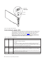
Understanding the adapter LEDs and labels . . . . .
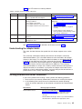
Understanding the adapter LEDs . . . . . . . .
Understanding the adapter labels . . . . . . . .
Solving problems with driver installation . . . . . . .
Solving an adapter communication problem . . . . .
Using PCISETUP . . . . . . . . . . . . . . .
DOS, Novell, Windows, or Windows 95 (adapter driver
DOS, Novell, Windows, or Windows 95 (adapter driver
OS/2 . . . . . . . . . . . . . . . . . .
Windows NT . . . . . . . . . . . . . . . .
Contacting IBM product support. . . . . . . . . .
Downloading code from the Web . . . . . . . . .
Tech tips and frequently asked questions . . . . . .
Other performance enhancements . . . . . . . . .
. . . . . . . .
. . . . . . . .
. . . . . . . .
. . . . . . . .
. . . . . . . .
. . . . . . . .
. . . . . . . .
. . . . . . . .
. . . . . . . .
. . . . . . . .
. . . . . . . .
. . . . . . . .
. . . . . . . .
. . . . . . . .
not in CONFIG.SYS)
in CONFIG.SYS)
. . . . . . . .
. . . . . . . .
. . . . . . . .
. . . . . . . .
. . . . . . . .
. . . . . . . .
.
.
.
.
.
.
37
37
37
38
38
38
42
42
43
44
45
45
46
46
46
47
47
47
47
47
47
47
Appendix A. CD-ROM content and
Software packages . . . . . .
Diskette images . . . . . . .
Product documentation . . . . .
.
.
.
.
.
.
.
.
49
50
50
51
software
. . . .
. . . .
. . . .
packages
. . . .
. . . .
. . . .
.
.
.
.
.
.
.
.
.
.
.
.
.
.
.
.
.
.
.
.
.
.
.
.
.
.
.
.
.
.
.
.
.
.
.
.
.
.
.
.
.
.
Appendix B. NDIS 2 device driver parameters . . . . . . . . . . . . 53
Appendix C. NDIS 2 device driver messages . . . . . . . . . . . . . 59
Appendix D. Novell NetWare Server driver parameters . . . . . . . . . 65
Appendix E. Novell NetWare Server messages . . . . . . . . . . . . 71
Appendix F. Novell NetWare DOS ODI driver parameters . . . . . . . . 77
Appendix G. Notices . . . . . . . . . . . . . . . . . . . . .
Trademarks . . . . . . . . . . . . . . . . . . . . . . . . .
Safety Information. . . . . . . . . . . . . . . . . . . . . . .
Telecommunications Safety Requirements in the United Kingdom . . . .
Statement of Compliance with the United Kingdom Telecommunications Act
1984 . . . . . . . . . . . . . . . . . . . . . . . . . .
Electronic Emission Notices . . . . . . . . . . . . . . . . . . .
Federal Communications Commission (FCC) Statement . . . . . . . .
Other Electronic Emission Notices for STP Media . . . . . . . . . . .
Industry Canada Class B Emission Compliance Statement . . . . . . .
Avis de conformité aux normes d’Industrie Canada . . . . . . . . .
European Norm (EN) Statement . . . . . . . . . . . . . . . .
Hinweis zur Elektromagnetischen Verträeglichkeit (EMVG) . . . . . . .
Japanese Voluntary Control Council for Interference (VCCI) Statement . .
Other Electronic Emission Notices for UTP Media . . . . . . . . . . .
Federal Communications Commission (FCC) Statement . . . . . . . .
iv
IBM 16/4 Token-Ring PCI Management Adapter
.
.
.
.
79
80
81
85
.
.
.
.
.
.
.
.
.
.
.
85
85
86
86
86
86
86
87
87
87
87
Industry Canada Class A Emission Compliance Statement . . . . . . .
European Norm (EN) Statement . . . . . . . . . . . . . . . .
Japanese Voluntary Control Council for Interference (VCCI) Statement . .
Taiwanese Class A Warning Statement . . . . . . . . . . . . . .
Power Cord Notices for UTP Media . . . . . . . . . . . . . . .
IBM License Agreement for Productivity Aids . . . . . . . . . . . . .
IF YOU DOWNLOAD OR USE THIS PROGRAM YOU AGREE TO THESE
TERMS. . . . . . . . . . . . . . . . . . . . . . . . .
NetWare Network Computing Products from IBM . . . . . . . . . . .
Protection and Security . . . . . . . . . . . . . . . . . . . . .
.
.
.
.
.
.
88
88
89
89
89
90
. 91
. 92
. 92
Glossary . . . . . . . . . . . . . . . . . . . . . . . . . . . 97
Index . . . . . . . . . . . . . . . . . . . . . . . . . . . . 103
Contents
v
vi
IBM 16/4 Token-Ring PCI Management Adapter
About this manual
This manual contains the information you need to install and use the IBM 16/4
Token-Ring PCI Management Adapter.
Also on the CD-ROM are the installation aids, device drivers, and documentation for
the adapter.
Who should read this manual
This manual is intended for use by network administrators and other end users of
the IBM 16/4 Token-Ring PCI Management Adapter who install token-ring adapter
hardware and software.
How this manual is organized
“Chapter 1. Introduction to the IBM 16/4 Token-Ring PCI Management Adapter” on
page 1 describes the adapters covered in this manual, gives a checklist for
installation, and describes some of the features of the adapters.
“Chapter 2. Installing the adapter hardware” on page 5 describes the procedure for
installing the adapter into your computer.
“Chapter 3. Software installation” on page 7 describes the procedure for software
installation for a number of network operating environments.
“Chapter 4. Problem solving” on page 37 describes troubleshooting procedures and
fixes that might be needed for your environment.
“Appendix A. CD-ROM content and software packages” on page 49 describes the
files that are on the adapter CD-ROM.
“Appendix B. NDIS 2 device driver parameters” on page 53 lists the NDIS 2
parameters, describes their usage, and lists their values.
“Appendix C. NDIS 2 device driver messages” on page 59 lists the NDIS 2 system
messages, explains the meaning, and lists user actions.
“Appendix D. Novell NetWare Server driver parameters” on page 65 lists the Novell
and LAN Client parameters, describes their usage, and lists their values.
“Appendix E. Novell NetWare Server messages” on page 71 lists the Novell and
LAN Client messages, explains the meaning, and lists user actions.
“Appendix F. Novell NetWare DOS ODI driver parameters” on page 77 lists the
Novell parameters, describes their usage, and lists their values.
“Appendix G. Notices” on page 79 lists the legal notices required for the IBM 16/4
Token-Ring PCI Management Adapter.
© Copyright IBM Corp. 2000
vii
Related publications
Refer to these publications for additional information:
v IBM Token-Ring Adapter Features
v ISO/IEC 8802-5:1998 Base Standard 4/16 HDX and related amendments
v IBM Token-Ring Network Problem Determination Guide, SX27-3710
v IBM LAN Technical Reference IEEE 802.2 and NETBIOS API, SC30-3587
v IBM Transmission Control Protocol/Internet Protocol Version 2.1 for DOS:
Programmer’s Reference, SC31-7046
v
v
v
v
v
v
v
v
LAN Adapter and Protocol Support Configuration Guide, S96F-8489
MPTS/2 Configuration Guide, S10H-9693
IBM LAN Server Command and Utilities, S10H-9686
Guide to LAN Server Books, S10H-9688
DOS LAN Services and User’s Guide, S10H-9684
Microsoft LAN Manager Installation and Configuration Guide
Microsoft Windows NT System Guide
Novell Workstation for DOS and MS Windows
v Novell NetWare installation and system administration manuals appropriate to the
version of Novell NetWare you have installed
IBM adapter books and other documentation are available on the IBM Networking
Web site:
http://www.ibm.com/networking
viii
IBM 16/4 Token-Ring PCI Management Adapter
Chapter 1. Introduction to the IBM 16/4 Token-Ring PCI
Management Adapter
This chapter describes the adapter, the contents of the adapter kits, and the other
materials you will need to install the adapter.
It is important that you are familiar with the computer in which the adapter will be
installed and the computer’s operating system and network software.
The adapter is 32-bit, bus-master, token-ring for the PCI bus architecture. The
unique, high-quality filter design supports connection to a token-ring network that is
wired with shielded twisted-pair (STP) or unshielded twisted-pair (UTP) cabling. The
adapter can be used in PCI-compatible slots that operate at speeds up to 33 MHz.
Features of this adapter include:
v Adapter management capability that is provided by SNMP.
v Desktop Management Interface (DMI) provided by the LAN Adapter Management
Agent. For an end-to-end management solution, you can use the agent in
conjunction with the Nways® Workgroup Manager Version 1.1 or later and Nways
Manager for AIX® Version 1.2 or later.
v Automatic ring-speed detection.
v Support for a wide variety of network operating systems and network
applications.
v Support for full-duplex (FDX), token-ring LAN operation.
v Support for microcode update.
v Automatic configuration of I/O, memory, ROM space, and interrupt level by PCI
BIOS on power-up.
v Designed for use with either a half-size or full-size, 5-V or 3.3-V signaling, 32-bit
or 64-bit PCI-bus slot.
v The IBM 16/4 Token-Ring PCI Management Adapter uses less than 1 watt of
power.
See IBM Token-Ring Adapter Features for information regarding the following
features:
v DHCP
v Remote Program Load (RPL)
v LAN Adapter Management Agent
v Route Switching
v Class of Service (CoS)
v Redundant NIC (RNIC)
v Tivoli® Management Agent
Adapter installation checklist
To install your adapter, complete the following steps. You might want to mark this
page for easy retrieval or make a copy for reference.
1. Prepare for installation. You will need the following items:
v The manual provided with your computer
v The manual provided with your network operating system or network
application
v Your operating system and network application software
© Copyright IBM Corp. 2000
1
2. Check the shipping package contents list “Package contents”.
3. Install the adapter hardware. See “Chapter 2. Installing the adapter hardware”
on page 5.
4. Install the adapter software. See “Chapter 3. Software installation” on page 7.
After the software is installed, installation is complete.
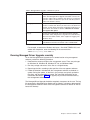
Environment limitations on number of adapters
There is a limit to the number of adapters that can be accommodated in certain
operating environments. The limits are listed in the following table.
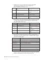
Table 1. Environment limitations
Device Driver
Novell ODI OS/2® Client
Novell ODI DOS Client
NDIS 2.0 DOS
Maximum Number of adapters
2
1
1
Package contents
The IBM 16/4 Token-Ring PCI Management Adapter comes with the following
features:
v Automatic Configuration and Power Interface (ACPI)/PCI power management
feature
v Wake on LAN feature
These features are described in the following sections.
Automatic Configuration and Power Interface (ACPI)
If your computer supports ACPI, then it has built-in energy-saving capabilities.
When ACPI is enabled (usually through the computer BIOS settings), the operating
system is allowed to control the power management features of your computer. Not
all operating systems support ACPI BIOS mode. Refer to your operating system
documentation to determine if ACPI is supported. Refer to your computer system
documentation to determine if ACPI BIOS is offered and the method by which it can
be enabled. The adapter implements the PCI Bus Power Management Interface
Specification Version 1.0 that works together with ACPI. Under control of the
operating system, the adapter (and the entire system) can be placed in various
power-saving modes and be dynamically configured to look for network
protocol-specific events. Upon detection of these events, the adapter can signal a
wake-up condition which will bring the system to a fully-powered (operational) state.
Some systems might need to be configured through BIOS settings
(configuration/setup utilities) to allow PCI devices to wake a system. Refer to your
computer system documentation for automatic power-on feature settings (or PCI
wake-up features).
Wake on LAN
Adapters that support this feature can turn on a system that is powered off. The
adapter uses an auxiliary 3-volt power pin that is available on the PCI bus
beginning with PCI version 2.2. No additional auxiliary power cables are required.
The 3-volt PCI auxiliary power pin supplies power to the adapter. A control register
on the adapter determines whether the adapter is powered on by the 3-volt auxiliary
power source. This register is controlled by the system BIOS. If the BIOS enables
the control register bit, then the adapter always has a source of power, even when
2
IBM 16/4 Token-Ring PCI Management Adapter
the system is powered off (system power cord is connected to a live power outlet).
When the system is powered off, the adapter automatically inserts into the network
and looks for a special frame. This frame is commonly referred to as a magic
packet. Upon detection of the magic packet, the adapter signals the system to turn
on the power supply, thus turning on the computer system. The magic packet is a
frame sent by another computer system usually running an application that provides
remote system management.
Attention: Some PCs with multiple PCI slots that support Wake on LAN and
3.3-volt auxiliary power may not have an adequate 3.3-volt power supply to power
more than just a few of the slots with auxiliary 3.3 volts. Check with your PC
supplier to determine the number of PCI slots that can be concurrently populated,
and still meet the current limit of 375 mA per slot (for auxiliary 3.3 volts). This limit
is specified in the PCI Bus Power Management Interface Specification Revision 1.1.
Chapter 1. Introduction to the IBM 16/4 Token-Ring PCI Management Adapter
3
4
IBM 16/4 Token-Ring PCI Management Adapter
Chapter 2. Installing the adapter hardware
This chapter describes how to install the IBM 16/4 Token-Ring PCI Management
Adapter.
Installing the adapter
Your adapter comes configured from the factory with RPL/PXE and expansion ROM
enabled.
Before you begin to install this adapter, be sure to read “Safety Information” on
page 81.
To install your adapter, perform the following procedure:
1. Switch OFF the PC and all attached devices.
Note: In the U.K., by law, telephone line cables must be disconnected from
the PC before the power cord.
2. Remove the power cord from the outlet.
3. Remove all cables from your PC. Label each cable for easier reconnection at
the end of this procedure.
4. Follow the instructions provided in your PC manual for removing the cover or
otherwise accessing the adapter slots and inserting the adapter.
5. Install the adapter according to the instructions for adapter installation in the
manual that came with your PC.
6. Secure the adapter in the PCI slot with the retaining screw or other bracket
lockdown mechanism.
7. Reinstall all removed covers.
8. Connect the token-ring cable to the adapter and to the network. See “Selecting
adapter cables” for a description of the correct token-ring cables to use.
9. Reconnect all cables to your computer and then connect the power cord.
Follow all safety instructions.
Note: In the U.K., by law, the power cord must be connected before the
telephone line cable.
10. The hardware installation is complete. See “Chapter 3. Software installation” on
page 7.
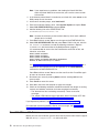
Selecting adapter cables
To connect your adapter to a token-ring network, you will need one of the cables
shown in Figure 1 on page 6. These cables are not included with the adapter.
© Copyright IBM Corp. 2000
5
Figure 1. STP and UTP cables
The network end of the cable must be compatible with the network faceplate or
other device to which the adapter will be connected.
Note: No more than one data cable may be connected to the adapter at a time.
Your adapter can use any of these cables.
6
IBM 16/4 Token-Ring PCI Management Adapter
Chapter 3. Software installation
This chapter describes how to install the driver software for your token-ring adapter.
To install the software, perform the following procedures:
1. Get the latest level of LAN driver updates for your operating system to ensure
that your code is at the latest level.
2. Make sure that your adapter has already been installed in your computer. If it
has not, follow the instructions in “Chapter 2. Installing the adapter hardware” on
page 5.
3. Get the driver for your environment. There are three places to find the driver.
We recommend the first one listed here. All three methods will place the driver
in a directory according to the structure in Table 2 on page 8.
v Method A: Get the driver from a software package on the IBM Networking
Web site. This will ensure that you get the latest driver.
a. Go to x:\startcd.htm (where x is your CD-ROM drive).
b. Select your adapter from the section IBM Networking Web site - current
information.
c. Select Downloads and select the appropriate software package for your
environment.
d. Run the package to expand the files. The driver will be placed in the
directory listed in Table 2 on page 8.
Note: You can also access the Web site directly at
http://www.ibm.com/networking/support.
v Method B: Use the driver shipped on this CD-ROM directly with your network
operating system’s installation software. Note the directory containing the
driver (see Table 2 on page 8).
v Method C: Get the driver from a software package shipped on this CD-ROM.
a. Go to x:\startcd.htm (where x is your CD-ROM drive).
b. Select your adapter from the section CD-ROM - release date information.
c. Select Downloads and choose the appropriate software package for your
environment.
d. Execute the package to expand the files. The driver will be placed in the
directory listed in Table 2 on page 8.
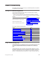
4. Install the driver. Use Table 3 on page 9 to find the location of the installation
instructions for your environment. We recommend that you install the latest
service pack for your operating environment before installing the adapter
software.
© Copyright IBM Corp. 2000
7
Table 2. Driver file directory structure
Operating System
®
Windows NT 4.0
Windows NT 3.51
Windows® 95 Retail
Windows 95 OSR2
Windows 98
Windows 2000
Windows for Workgroups
Novell NetWare Server and 32-bit Client
Novell NetWare DOS Requester (16-bit)
Novell NetWare OS/2 Requester (16-bit)
OS/2
DOS
8
IBM 16/4 Token-Ring PCI Management Adapter
Directory
\(root)
\win32
\win32
\(root)
\(root)
\(root)
\WFW
\NOVELL\NETWARE
\NOVELL\DOS
\NOVELL\OS2
\OS2
\DOS
Table 3. Installation instructions
Environment
Page
DOS with Windows Version 3.1x
NetWare Requester
22
DOS LAN Services
21
IBM TCP/IP for DOS (Version 2.1)
21
Windows for Workgroups with NDIS
33
DOS (without Windows)
NetWare Requester
22
DOS LAN Services
21
IBM TCP/IP for DOS (Version 2.1)
21
NetWare Requester
22
NDIS2
21
OS/2
OS/2 (MPTS)
19
NetWare Requester
20
OS/2 Warp Connect or Server
20
NetWare Server
NetWare Server Version 3.12
9
NetWare Server Version 4.11
12
NetWare Server Version 5.0
16
Novell Client
18
Windows 32-bit
Windows NT 3.51
23
Windows NT 4.0
24
Windows 95
25
Windows 98
28
Windows 2000
30
Remote Unattended Installation (Windows NT, Windows 95,
Windows 98, Windows 2000)
32
Novell IntranetWare Client for Windows NT
32
Novell Client for Windows 95
33
Managed Driver Upgrade (Windows NT, Windows 95,
Windows 98, Windows 2000)
34
Novell NetWare 3.12 Server
Before you start this installation, get the latest level of LAN driver updates for
NetWare 3.12 from Novell’s support Web site at http://support.novell.com. You
will install them during the following procedure.
If Novell NetWare Server is not installed on your machine, use the following
instructions. If it is installed, see the instructions in “Server driver installation in
existing NetWare 3.12 Server” on page 11.
Chapter 3. Software installation
9
Server driver installation in new NetWare 3.12 Server
Changes from the usual NetWare installation are necessary because this driver is
written to a new specification level that requires new NetWare loadable modules
(NLMs). The installation program is not aware of this, though, and these NLMs must
be loaded during installation of the server device driver and after the server
installation.
1. Create a diskette containing the extracted files from the NETWAREP.EXE
package file on the adapter CD-ROM.
2. Refer to Novell’s Installation and Upgrade manual for installation instructions.
Follow the procedure for the installation of Novell NetWare 3.12 until the
section titled “Load LAN Drivers” is next.
3. Insert the diskette that you created in step 1 into drive A. Enter the following
commands at the server prompt:
LOAD A:\NOVELL\NETWARE\NBI31X.NLM
LOAD A:\NOVELL\NETWARE\MSM31X.NLM
LOAD A:\NOVELL\NETWARE\TOKENTSM.NLM
Note: A message referring to protected-mode BIOS access might appear
before installation of Novell patches. It is for information only, and can
be ignored.
4. Load the server device driver. Enter the following command at the server
prompt:
LOAD X:\NOVELL\NETWARE\IBMTRPO.LAN DATARATE=M16
It is recommended for servers that the DataRate be set to M16 or M4, and
clients be set to Auto.
Note: See “Appendix D. Novell NetWare Server driver parameters” on page 65
for a complete list of parameters that can be specified in the LOAD
IBMTRPO command in the AUTOEXEC.NCF file.
5. Follow the instructions in the Novell manual, beginning with “Bind the Protocol
to the LAN Driver” and continue until you are in the file server STARTUP.NCF
file panel.
6. In addition to the instructions in the Novell manual, add the following line to
STARTUP.NCF:
Set Minimum Packet Receive Buffers = 48
Note: Increase the minimum packet receive buffers by 48 for each additional
adapter that is installed.
7. Perform the instructions in “Create an AUTOEXEC.NCF file” in the Novell
manual. Add the following lines to the AUTOEXEC.NCF file immediately after
the IPX INTERNAL NET statement (replace C:\SERVER.312\ with the location of
the NetWare Server program):
LOAD
LOAD
LOAD
LOAD
BIND
C:\SERVER.312\NBI31X.NLM
C:\SERVER.312\MSM31X.NLM
C:\SERVER.312\TOKENTSM.NLM
C:\SERVER.312\IBMTRPO.LAN NAME=IBMLS1 DATARATE=M16
IPX TO IBMLS1 NET=<unique net number>
Make sure that the line containing IBMTRPO.LAN has the complete path
name.
10
IBM 16/4 Token-Ring PCI Management Adapter
Notes:
a. See “Appendix D. Novell NetWare Server driver parameters” on page 65 for
a complete list of parameters that you can specify on the LOAD IBMTRPO
command in the AUTOEXEC.NCF file.
b. If you experience any problems after loading the Novell NLM files, contact
Novell to ensure that you have the current version of these files.
Press Esc and answer Yes to save the new file to disk. Press Esc again to
return to the server console.
8. Shut down your server by entering down and then entering exit from the server
prompt.
9. Make sure that the diskette you created in step 1 is inserted in drive A. Enter
the following commands at the server prompt. You might be prompted to
perform a file overwrite; it is OK to overwrite these files.
COPY
COPY
COPY
COPY
COPY
A:\NOVELL\NETWARE\NBI31X.NLM C:\SERVER.312
A:\NOVELL\NETWARE\MSM31X.NLM C:\SERVER.312
A:\NOVELL\NETWARE\TOKENTSM.NLM C:\SERVER.312
A:\NOVELL\NETWARE\IBMTRPO.LAN C:\SERVER.312
A:\NOVELL\NETWARE\IBMTRPO.LDI C:\SERVER.312
10. Go to the Novell server directory and enter server at the DOS prompt to
restart the server.
11. Install the patches obtained earlier now. Make sure to select the V3.31 ODI
LAN Updates for Hardware if given the opportunity.
12. Check for the following conditions to determine whether the adapter is working
correctly and whether installation has been completed successfully:
v The device driver files are loading successfully. There are no error
messages.
v The adapter LEDs indicate normal operation: Green ON, Amber OFF. See
“Understanding the adapter LEDs and labels” on page 43.
If you experience problems, see “Chapter 4. Problem solving” on page 37.
For information concerning NetWare Server error messages, see “Appendix E.
Novell NetWare Server messages” on page 71.
Server driver installation in existing NetWare 3.12 Server
If Novell NetWare is already installed in your computer, perform the following steps
to install the adapter server device driver.
1. Create a diskette containing the extracted files from the NETWAREP.EXE file
on the adapter CD-ROM.
2. Install the patches obtained earlier now. Make sure to select the V3.31 ODI
LAN Updates for Hardware if given the opportunity. Return to the server
console when the installation is complete.
3. Make sure that the diskette you created in step 1 is inserted in drive A. Enter
the following commands at the server prompt. You might be prompted to
perform a file overwrite; it is OK to overwrite these files.
COPY
COPY
COPY
COPY
COPY
A:\NOVELL\NETWARE\NBI31X.NLM C:\SERVER.312
A:\NOVELL\NETWARE\MSM31X.NLM C:\SERVER.312
A:\NOVELL\NETWARE\TOKENTSM.NLM C:\SERVER.312
A:\NOVELL\NETWARE\IBMTRPO.LAN C:\SERVER.312
A:\NOVELL\NETWARE\IBMTRPO.LDI C:\SERVER.312
Chapter 3. Software installation
11
Note: If you experience any problems after loading the Novell NLM files,
check the Novell Web site to ensure that you have the current version
of these files.
4. In the directory where Novell is installed on your hard disk, enter server at the
DOS prompt to start the server.
5. At the server console prompt, enter load install.
6. From the Installation Options menu, select System Options and press Enter.
7. Select Edit STARTUP.NCF File and press Enter.
8. Add the following line to the STARTUP.NCF file:
Set Minimum Packet Receive Buffers = 48
Note: Increase the minimum packet receive buffers by 48 for each additional
adapter that is installed.
9. Press Esc and then answer Yes to save changes to the STARTUP.NCF file.
10. Select Edit AUTOEXEC.NCF File and press Enter. Edit this file and, after the
IPX internal net statement, include the following statements. (Replace
C:\SERVER.312\ with the location of the NetWare Server program.)
It is recommended for servers that the DataRate be set to M16 or M4, and
clients be set to Auto.
LOAD
LOAD
LOAD
LOAD
BIND
C:\SERVER.312\NBI31X
C:\SERVER.312\MSM31X
C:\SERVER.312\TOKENTSM
C:\SERVER.312\IBMTRPO NAME=IBMLS1 DATARATE=M16
IPX TO IBMLS1 NET=<unique net number>
See “Appendix D. Novell NetWare Server driver parameters” on page 65 for a
complete list of parameters that can be specified on the LOAD IBMTRPO
command in the AUTOEXEC.NCF file.
Press Esc and then answer Yes to save the new file to disk. Press Esc again
to return to the server console.
11. Shut down your server by entering down and then entering exit from the
server prompt.
12. Enter server to restart the server.
13. Shut down and restart the computer to apply the changes.
14. Check for the following conditions to determine whether the adapter is working
correctly and whether installation has been completed successfully:
v The device driver files are loading successfully. There are no error
messages.
v The adapter LEDs indicate normal operation: Green ON, Amber OFF. See
“Understanding the adapter LEDs and labels” on page 43.
If you experience problems, see “Chapter 4. Problem solving” on page 37.
For information concerning NetWare Server error messages, see “Appendix E.
Novell NetWare Server messages” on page 71.
Novell NetWare 4.11 Server
Before you start this installation, get the latest level of patches from Novell’s support
Web site at http://support.novell.com and install them.
12
IBM 16/4 Token-Ring PCI Management Adapter
If Novell NetWare is not installed on your machine, use the following instructions. If
it is installed, follow the instructions in “Server driver installation in existing NetWare
4.11 Server” on page 14.
Server driver installation in new NetWare 4.11 Server
Changes from the usual NetWare installation are necessary because this driver is
written to a new specification level that requires new NetWare loadable modules
(NLMs). The installation program is not aware of this, though, and these NLMs must
be loaded during installation of the server device driver and after the server
installation.
Note: A message referring to protected-mode BIOS access might appear before
installation of Novell patches. It is for information only, and can be ignored.
1. Create a diskette containing the extracted files from the NETWAREP.EXE
package file on the adapter CD-ROM.
2. When you see INSTALL Found the following : PCI LAN Controller
xxxx.xxxx.xxxx press Enter. Then press the Insert key to install the unlisted
driver.
3. Press Alt+Esc to toggle to the server console, and enter the following LOAD
statements (make sure that the diskette that you created in step 1 is inserted
in drive A):
LOAD A:\NOVELL\NETWARE\MSM.NLM
LOAD A:\NOVELL\NETWARE\TOKENTSM.NLM
4. Press Alt+Esc to toggle back to the INSTALL panel.
5. Press F3 on the next panel to specify a:\novell\netware as the directory path.
6. Press Enter and then follow the instructions on the panel to complete the
installation of the driver. If you need to make any custom configuration
changes to the driver, do so at this time.
7. Follow the instructions in the Novell manual Create an AUTOEXEC.NCF file. In
addition to the instructions in the manual, add the following lines to the
AUTOEXEC.NCF file immediately after the IPX INTERNAL NET statement (if
necessary, replace c:\nwserver with the location of the SERVER.EXE
executable):
LOAD
LOAD
LOAD
LOAD
C:\NWSERVER\NBI.NLM
C:\NWSERVER\MSM.NLM
C:\NWSERVER\TOKENTSM.NLM
C:\NWSERVER\IBMTRPO.LAN NAME=IBMLS1 DATARATE=M16
Note: There will be existing LOAD and BIND IPX statements in the
AUTOEXEC.NCF. Delete the LOAD statement (we have replaced it with
stated LOAD C:\NWSERVER\IBMTRPO.LAN statement). Also, make
any needed modifications to the existing BIND IPX statement Refer to
the ″Bind the Protocol to the LAN Driver″ section of the Novell manual
for additional information.
See “Appendix D. Novell NetWare Server driver parameters” on page 65 for a
complete list of parameters that can be specified on the LOAD IBMTRPO
command in the AUTOEXEC.NCF file.
8. Press Esc and answer YES to save the new file to disk. Press Esc again to
return to the server console.
9. Type the following commands from the server prompt to shut down the server
and exit to DOS: down, then exit.
Chapter 3. Software installation
13
10. Perform the following COPY commands, making sure that the diskette that you
created in step 1 is inserted in drive A. Note that it will prompt you at each of
the following files to ask if you want to perform a file overwrite; it is OK to
overwrite these files.
COPY
COPY
COPY
COPY
COPY
A:\NOVELL\NETWARE\NBI.NLM C:\NWSERVER
A:\NOVELL\NETWARE\MSM.NLM C:\NWSERVER
A:\NOVELL\NETWARE\TOKENTSM.NLM C:\NWSERVER
A:\NOVELL\NETWARE\IBMTRPO.LAN C:\NWSERVER
A:\NOVELL\NETWARE\IBMTRPO.LDI C:\NWSERVER
11. Go to the Novell server directory and enter server at the DOS prompt to
restart the server.
12. Install the latest available Novell patches for NetWare 4.11 now. Make sure to
select the Version 3.31 ODI LAN Updates for Hardware if given the
opportunity.
13. Issue the down command to bring the server down.
14. Reboot the server by entering restart server.
15. Check for the following conditions to determine whether the adapter is working
correctly and whether installation has been completed successfully:
v The device driver files are loading successfully. There are no error
messages.
v The adapter LEDs indicate normal operation. Green ON, Amber OFF. See
“Understanding the adapter LEDs and labels” on page 43.
If you experience problems, see “Chapter 4. Problem solving” on page 37.
For information concerning NetWare Server error messages, see “Appendix E.
Novell NetWare Server messages” on page 71.
Server driver installation in existing NetWare 4.11 Server
If Novell NetWare is already installed in your computer, perform the following steps
to install the adapter server device driver.
Note: If you are altering the configuration of a previously loaded adapter, unload
that adapter before proceeding with these instructions.
1. Create a diskette containing the extracted files from the NETWAREP.EXE file
on the adapter CD-ROM.
2. Be sure that your adapter has already been installed in your computer. If it has
not, follow the instructions in “Chapter 2. Installing the adapter hardware” on
page 5.
3. Install the latest available Novell patches for NetWare 4.11. Make sure to
select the Version 3.31 ODI LAN Updates for Hardware if given the
opportunity. Return to the server console when the installation is complete.
4. Issue the down command from the server prompt to bring the server down.
5. Reboot the server by entering restart server.
6. Check to see if the device driver is loaded. If it is, unload it using the following
command: unload ibmtrpo
7. Type load install on the server.
8. Select Driver Options.
9. Select Configure Network Drivers.
10. Select Select Drivers.
11. Press the Insert key to install the unlisted driver.
14
IBM 16/4 Token-Ring PCI Management Adapter
12. Insert the diskette that you created in step 1.
13. Press F3 and specify the path a:\novell\netware.
14. Follow the instructions on the panels to complete the installation of the driver.
If you need to make any custom configuration changes to the driver, do so at
this time.
15. Follow the instructions in the Novell manual Create an AUTOEXEC.NCF file. In
addition to the instructions in the manual, add the following lines to the
AUTOEXEC.NCF file, immediately after the IPX INTERNAL NET statement (if
necessary, replace c:\nwserver with the actual location of the SERVER.EXE
executable):
LOAD
LOAD
LOAD
LOAD
C:\NWSERVER\NBI.NLM
C:\NWSERVER\MSM.NLM
C:\NWSERVER\TOKENTSM.NLM
C:\NWSERVER\IBMTRPO.LAN NAME=IBMLS1 DATARATE=M16
Note: There will be existing LOAD and BIND IPX statements in the
AUTOEXEC.NCF. Delete the LOAD statement (we have replaced it with
the stated LOAD C:\NWSERVER\IBMTRPO.LAN statement).
Also, make any needed modifications to the existing BIND IPX statement.
Refer to the ″Bind the Protocol to the LAN Driver″ section of the Novell manual
for additional information.
See “Appendix D. Novell NetWare Server driver parameters” on page 65 for a
complete list of parameters that can be specified on the LOAD IBMTRPO
command in the AUTOEXEC.NCF file.
16. Press Esc and answer YES to save the new file to disk. Press Esc again to
return to the server console.
17. Type the following commands from the server prompt to shut down the server
and exit to DOS: down, and then exit.
18. Type the following commands, making sure that the diskette that you created
in step 1 is inserted in drive A. Note that it will prompt you at each of the
following files to ask if you want to perform a file overwrite; it is OK to
overwrite these files.
COPY
COPY
COPY
COPY
COPY
A:\NOVELL\NETWARE\NBI.NLM C:\NWSERVER
A:\NOVELL\NETWARE\MSM.NLM C:\NWSERVER
A:\NOVELL\NETWARE\TOKENTSM.NLM C:\NWSERVER
A:\NOVELL\NETWARE\IBMTRPO.LAN C:\NWSERVER
A:\NOVELL\NETWARE\IBMTRPO.LDI C:\NWSERVER
19. Go to the Novell server directory and enter server at the DOS prompt to
restart the server.
20. Check for the following conditions to determine whether the adapter is working
correctly and whether installation has been completed successfully:
v The device driver files are loading successfully. There are no error
messages.
v The adapter LEDs indicate normal operation. Green ON, Amber OFF. See
“Understanding the adapter LEDs and labels” on page 43.
If you experience problems, see “Chapter 4. Problem solving” on page 37.
For information concerning NetWare Server error messages, see “Appendix E.
Novell NetWare Server messages” on page 71.
Chapter 3. Software installation
15
Novell NetWare 5.0 Server
If Novell NetWare is not installed on your machine, use the following instructions. If
it is installed, follow the instructions in “Server driver installation in existing NetWare
5.0 Server” on page 17.
Server driver installation during NetWare 5.0 Server installation
Installation of the network board and its device driver occurs during the combined
storage device and network board installation step. Use the following instructions to
install the network board and its driver during a new NetWare 5.0 Server
installation.
1. Create a device driver installation diskette containing the extracted files from the
NETWAREP.EXE package file on the adapter CD-ROM.
2. Select a storage device and a network board:
v Select and configure the storage device.
Storage devices such as hard disks, CD-ROMs, and tape devices require a
software driver to communicate with the storage adapter. The software driver
for the storage device is called a custom device module (CDM). Each type of
storage device requires a CDM.
The installation program auto-detects many types of storage devices such as
IDE drives, SCSI drives, CD-ROM drives, and tape drives. If your storage
device is not detected, choose the appropriate driver from the list of available
drivers provided with NetWare 5 or add a new driver from a diskette. CDMs
can be obtained from the storage device manufacturer.
v Select and configure the network board.
The software driver for a network board is called a LAN driver. The
installation program auto-detects many types of network boards. If your
network board is not detected, choose the driver for the network board from
the list provided with NetWare 5 or use a new or updated driver from the
diskette that you created in step 1.
The network board must be installed and configured correctly. For servers, it
is recommended that DATARATE be set to M16 or M4, and clients be set to
Auto. You might be able to influence certain network board properties by
configuring the system and the network board or both.
v Load a NetWare Loadable Module TM program, if required.
Certain server and network configurations might require you to load a
NetWare Loadable Module (NLM) before you can complete the server
installation. An example is loading ROUTE.NLM for a token-ring environment
that requires it.
16
IBM 16/4 Token-Ring PCI Management Adapter
3. Add, delete, or modify drivers as needed.
v To add a driver:
a. In the Options box, select Modify.
b. Select the driver and press Enter.
c. Press Insert to select from a list of drivers provided with NetWare.
d. Press Insert again to install a driver from diskette.
v To
a.
b.
c.
v To
delete a driver:
In the Options box, select Modify.
Select the driver and press Enter.
Select the driver to delete and press Delete.
modify a driver:
a. In the Options box, select Modify.
b. Select the driver and press Enter.
c. Select the driver to modify and press Enter.
d. Select the property to modify.
Server driver installation in existing NetWare 5.0 Server
The following procedure explains how to use NWCONFIG to load a LAN driver and
bind a protocol.
1. Create a diskette containing the extracted files from the NETWAREP.EXE
package file on the adapter CD-ROM.
2. At the server console prompt, enter NWCONFIG.
3. Select Driver Options → Configure network drivers.
4. To select the driver from all of the available drivers, select Select a driver. The
screen will display a list of all available drivers.
5. Press Insert. Follow the instructions on the panels. Use the diskette that you
created in step 1 when you are prompted to supply an unlisted driver. The
directory is a:\novell\netware.
Chapter 3. Software installation
17
Note: For some drivers, a message might appear indicating that the driver
must be loaded manually (at the console prompt). To load a driver
manually, follow the screen prompts or press F1 for more information.
6. Set protocols. When the window containing protocol choices is displayed,
select the protocol that you want to use and press the space bar. If you select
TCP/IP, enter the IP address and the IP mask.
7. Set parameters. Use the down arrow key to move the cursor to the parameter
window. Enter parameter values as needed. Press F1 for help.
It is recommended for servers that the Data Rate be set to 4 Mbps or 16
Mbps, and clients be set to Automatic.
In some cases, the system displays a pop-up list of values for the field from
which you select the desired value. In other cases, you must type in a value
and press Enter to move to the next field.
8. To specify a particular frame type for a token-ring driver, press F3 to display a
list of frame types. Use the arrow keys to move up and down the list.
9. Press Enter to select a frame type.
10. When finished, press F10.
If you do not specify a particular frame type, all frame types are loaded
automatically, but only those found on the network are actually bound to the
driver.
11. Select Save parameters and load driver.
12. Confirm bindings of the protocol with the driver and the network number.
13. To add another adapter, shut down the server, power off the server, and insert
the additional driver. NetWare will load the appropriate driver automatically.
Then repeat step 12.
Novell Client DOS/Windows 3.1x
1. Download Novell Client DOS/Windows 3.1x Version 2.5 or later from Novell’s
Web site at http://support.novell.com.
2. Unzip the downloaded file to a directory on your computer.
3. Exit Windows.
4. From a DOS prompt, go to the directory where you put the file. Run
INSTALL.EXE.
5. Select Yes or No to respond to the Novell License Agreement.
6. Select Novell Client Windows Support and Work Station Manager 3.X.
Press F10 to save and continue.
7. Select 32-bit LAN Drivers and press F10 to save and continue.
8. Select USER SPECIFIED 32-Bit Driver and press Enter.
9. Insert the CD-ROM or the diskette containing the device drivers into the
appropriate drive. Enter the path to the 32-bit ODI driver: x:\novell\netware
where x is your CD-ROM drive letter. The panel should say
IBM Token-Ring PCI Family Adapter
Press Enter, configure the parameters, and press F10 to save and continue.
10. At the panel entitled Installation Configuration Summary, confirm that the
values are what you selected, and press F10 to save and continue.
The files will be copied at this point.
11. Reboot the computer and start Windows to connect to and log in to your
server.
18
IBM 16/4 Token-Ring PCI Management Adapter
12. Check for the following conditions to determine whether the adapter is working
correctly and whether installation has been completed successfully:
v The device driver files are loading successfully. There are no error
messages.
v The adapter LEDs indicate normal operation: Green ON, Amber OFF. See
“Understanding the adapter LEDs and labels” on page 43.
If you experience problems, see “Chapter 4. Problem solving” on page 37.
OS/2 NDIS 2 device driver using MPTS
Use the following procedure to install the OS/2 NDIS 2 device driver using the
Multiple Protocol Transport Services (MPTS).
1. When updating an existing device driver, error message X100035, which
indicates that the driver could not be installed and the previous version could
not be restored, can be prevented by performing the following steps before
beginning the update. This is particularly useful when the existing driver was
installed from the adapter CD-ROM.
v From an OS/2 window, go to the drive where OS/2 is installed. Change to
the ibmcom subdirectory (where x is your drive letter):
x:
cd \ibmcom
v Enter the following two commands:
attrib -r ibmtrp.* /s
attrib -r la1*.msg
2. Start MPTS by performing either of the following actions:
v From the OS/2 desktop, double-click the MPTS icon.
v From an OS/2 window, go into the ibmcom subdirectory and enter mpts at
the OS/2 prompt.
3. Select OK on the MPTS logo panel.
4. Select Install. You will be prompted for the source of the .NIF file. Enter the
path to the driver directory. Select OK once the Installation Complete message
appears. You will return to the main menu.
5. Select Configure in the MPTS dialog box.
6. On the Configure panel, make sure that LAN adapters and protocols is
preselected and then select Configure at the bottom of the panel.
7. In the Configuration panel, in the Network Adapters group box, select IBM
Token-Ring PCI Family Adapter (IBMTRP.OS2) and select ADD.
Note: You can edit parameter settings for this adapter. Highlight your adapter
in the Current Configuration list box and select Edit.
8. In the Protocols list box, select the protocols used by your network application.
Highlight each protocol and select ADD.
Note: If you are not sure which ones to use, select IBM IEEE 802.2 and IBM
OS/2 NetBIOS protocol drivers or ask your network administrator.
The protocol drivers you have selected will appear under the adapter driver
name in the Current Configuration list box.
Note: You can edit parameter settings for the protocols. Highlight a protocol
and select Edit.
Chapter 3. Software installation
19
9. Select OK when you have finished selecting and editing protocols in the MPTS
Configuration panel.
10. Select Close on the Configure panel.
11. Select Exit in the MPTS dialog box.
12. Select Exit on the Update CONFIG.SYS panel to update the CONFIG.SYS
file.
13. Select OK when you get the message that the CONFIG.SYS has been
successfully updated.
14. Select Exit on the Exiting MPTS panel.
15. Shut down and restart the computer to apply the changes.
16. At system startup, check for the following conditions to determine whether the
adapter is working correctly and whether installation has been completed
successfully:
v The device driver files loaded successfully. There are no error messages.
v The adapter LEDs indicate normal operation: Green ON, Amber OFF.
If you experience problems, see “Chapter 4. Problem solving” on page 37.
For information concerning NDIS driver error messages, see “Appendix C. NDIS 2
device driver messages” on page 59.
OS/2 NDIS 2 device driver using other installation programs
Use the following procedure to install the OS/2 NDIS 2 device driver using
installation programs other than MPTS.
1. Insert the CD-ROM or the NDIS Drivers diskette into the appropriate drive.
2. Use your product documentation to install the driver (IBMTRP.OS2) that is
located in the root directory on both the CD-ROM and diskette.
3. Modify the parameters if needed. See “Appendix B. NDIS 2 device driver
parameters” on page 53 for a list and explanation of parameters.
IBM TCP/IP for OS/2 and Warp Connect are examples of products that provide
driver installation programs.
4. Shut down and restart the computer to apply the changes.
5. Check for the following conditions to determine whether the adapter is working
correctly and whether installation has been completed successfully:
v The device driver files load successfully. There are no error messages.
v The adapter LEDs indicate normal operation: Green ON, Amber OFF.
If you experience problems, see “Chapter 4. Problem solving” on page 37.
For information concerning NDIS driver error messages, see “Appendix C. NDIS 2
device driver messages” on page 59.
OS/2 Novell NetWare Requester
Before installation, copy IBMTRPO.SYS from the CD-ROM to the root directory
containing your Novell NetWare Requester source files.
Refer to the workstation basics and installation manuals from Novell. When a dialog
box titled Requester Installation appears during the installation process, perform the
following procedure:
20
IBM 16/4 Token-Ring PCI Management Adapter
1. If you are installing the NetWare Requester on a workstation, select Edit
CONFIG.SYS and Copy All Files.... If the NetWare Requester is already
installed on the workstation and only a driver update is needed, then select
Only Edit CONFIG.SYS....
2. On the next panel, specify the name of the adapter driver: IBMTRPO.SYS.
3. When you get to the panel labeled Copy ODI LAN Driver files, select Copy
only the default driver.
4. Follow the instructions on the panels to continue installation.
5. When Installation Complete appears in the Requester window, go to the
Configuration menu and select This workstation....
6. Select Edit to accept the default location for the NET.CFG file.
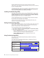
7. In the edit box titled Current NET.CFG File Contents, type the following lines:
link driver IBMTRPO
SLOT 10001
link support
BUFFERS 8 4096
Notes:
a. See “Appendix F. Novell NetWare DOS ODI driver parameters” on page 77
for a complete list of parameters that you can specify in the NET.CFG file.
b. To enable source routing, changes will have to be made to the
CONFIG.SYS file. Refer to Novell’s Workstation for OS/2 manual for
instructions on how to enable source routing.
c. The lines in the NetWare Requester section of the CONFIG.SYS file must
be in a certain order. Do not reorder the lines in this section of
CONFIG.SYS. Refer to the Novell manuals for more information.
8. Select Save to complete the NetWare Requester installation.
9. Reboot the computer to apply the changes.
Note: To make changes in the NetWare Requester configuration, double-click
the Novell icon on the desktop. Double-click the Install icon in the Novell
window. Go to the Configuration and select This workstation.... Make
sure that the correct NET.CFG is shown in the next dialog box and select
Edit. Edit the NET.CFG file in the edit box titled Current NET.CFG File
Contents. When the changes are complete, select Save and reboot the
computer to apply the changes.
10. Check for the following conditions to determine whether the adapter is working
correctly and whether installation has been completed successfully:
v The device driver files loaded successfully. There are no error messages.
v The adapter LEDs indicate normal operation: Green ON, Amber OFF.
If you experience problems, see “Chapter 4. Problem solving” on page 37.
DOS NDIS 2
Use the following procedure to install the DOS NDIS 2 device driver:
1. Insert the CD-ROM or the NDIS Drivers diskette into the appropriate drive.
2. Use your operating system documentation to install the driver (IBMTRP.DOS).
This driver is located in the \dos subdirectory on both diskette and the CD-ROM.
3. Modify the parameters, if needed. See “Appendix B. NDIS 2 device driver
parameters” on page 53.
Chapter 3. Software installation
21
Note: If you use Microsoft Windows for Workgroups and want to configure the
NetAddress parameter for the NDIS device driver, remember to enclose
the address in double quotes (" "). The NetAddress parameter is used to
set a locally administered address for the adapter.
4. Shut down and restart the computer to apply the changes.
5. Check for the following conditions to determine whether the adapter is working
correctly and whether installation has been completed successfully:
v The device driver files load successfully. There are no error messages. If
error messages are displayed or if you do not see messages that indicate
that the drivers have been installed, see “Starting the troubleshooting
process” on page 37.
v The adapter LEDs indicate normal operation: Green ON, Amber OFF.
If you experience problems, see “Chapter 4. Problem solving” on page 37.
For information concerning NDIS driver error messages, see “Appendix C. NDIS 2
device driver messages” on page 59.
DOS Novell NetWare Requester (16-bit)
The 16-bit DOS Novell NetWare Requester environment supports access to servers
running Novell NetWare 3.11 or later.
To install the IBMTRPO.EXE ODI driver on a computer running DOS, perform the
following procedure:
Note: Consult your Novell NetWare documentation for instructions regarding how to
create the NetWare Client for DOS and MS Windows diskettes.
1. Create a diskette containing the extracted files from the DOSODIP.EXE file on
the adapter CD-ROM.
2. Insert the NetWare Client for DOS and MS Windows Disk 1 into the
appropriate drive.
3. At the command prompt, type x:, where x is your drive letter, and then press
Enter.
4. Type install and then press Enter.
5. Follow the instructions as they appear. In step 5 of those instructions, select
the driver for your network board by scrolling down through Network Boards,
highlighting Other Drivers, and pressing Enter.
6. Insert the CD-ROM or the diskette that you created in step 1 of this procedure
into the appropriate drive. When prompted, specify the location to the chosen
media and press Enter. Specify the path as A:\NOVELL\DOS (or at
X:NOVELL\DOS for the CD-ROM version).
7. Highlight your adapter and press Enter.
8. At this time you can change the default parameters. When you complete the
changes, press F10. “Appendix F. Novell NetWare DOS ODI driver parameters”
on page 77 contains the parameters that can be configured in the NET.CFG
file.
9. Follow the instructions presented to complete the installation.
Note: If source routing is required, edit the STARTNET.BAT file that is in the
client directory (usually C:\NWCLIENT) and add the following line after
the IPXODI statement:
22
IBM 16/4 Token-Ring PCI Management Adapter
C:\NWCLIENT\ROUTE
10. Shut down and restart the computer to apply the changes.
11. Check for the following conditions to determine whether the adapter is working
correctly and whether installation has been completed successfully:
v The device driver files load successfully with no error messages. If error
messages are displayed or if you do not see messages that indicate that the
drivers were installed, see “Starting the troubleshooting process” on
page 37.
v The adapter LEDs indicate normal operation: Green ON, Amber OFF.
If you experience problems, see “Chapter 4. Problem solving” on page 37.
Windows NT Version 3.51
The following procedure assumes that Windows NT 3.51 has already been installed
with networking support. It is highly recommended that you install Service Pack 5
from Microsoft before installing the driver.
1. Log on to Windows NT as an administrator.
2. From the Main program group within the Program Manager, double-click the
Control Panel icon.
3. In the Control Panel window, double-click the Network icon.
4. In the Network Setting, select Add Adapter.
5. In the Add Network Adapter dialog box, click the drop-down list for Network
Adapter Card. Scroll down the list and select Other → Requires disk from
manufacturer. Then select Continue.
6. Insert the CD-ROM or the diskette containing the device drivers into the
appropriate drive. When prompted, enter the path to the driver directory and
select OK.
7. Select OK to accept the drive and path information.
8. In the Select OEM Option dialog box, select IBM Token-Ring PCI Family
Adapter.
Several work-in-progress panels are displayed, indicating that the driver and its
supporting files are being copied to your computer’s hard disk.
9. The Network Control panel is displayed again. There should be an entry in the
Installed Adapter Cards list for each token-ring adapter found in the computer.
To change default values for an adapter, select that adapter in the Installed
Adapters list box, and then select Configure. Make the necessary changes
and select OK.
Note: Make sure that all of the appropriate protocols are installed to connect
to the network. Consult your network administrator if you are unsure of
what protocols need to be installed.
10. Select OK at the top right to complete the installation.
Note: If TCP/IP is installed as a protocol on the computer, you will now see
the TCP/IP configuration panel. Enter all necessary information and
select OK.
11. The following message will be displayed:
Your network settings have changed.
You will need to exit and restart Windows NT so that the new
settings can take effect.
Chapter 3. Software installation
23
Select Restart now in order to have Windows NT automatically restart your
computer.
Note: You might need to reinstall Service Pack 5 due to changes to your
services or protocols during installation.
12. Check for the following conditions to determine whether the adapter is working
correctly and whether installation has been completed successfully:
v The device driver files loaded successfully.
v There are no error messages logged for the IBMTRP service in the Event
Viewer.
v The adapter LEDs indicate normal operation: Green ON, Amber OFF.
If you experience problems, see “Chapter 4. Problem solving” on page 37.
Windows NT Version 4.0
The following procedure assumes that Windows NT 4.0 has already been installed
with networking support. It is highly recommended that you install Service Pack 3 or
later from Microsoft before installing the driver.
1. Log on to Windows NT as an administrator.
2. Select Start → Settings → Control Panel.
3.
4.
5.
6.
7.
From the Control Panel window, double-click the Network icon.
Select the Adapters tab.
Select Add.
You will see a dialog box that includes a list of adapters. Select Have Disk....
Insert the CD-ROM or the diskette containing the device drivers into the
appropriate drive. When prompted, enter the path to the root directory of the
CD-ROM or diskette and select OK.
8. In the Select OEM Option dialog box, select IBM Token-Ring PCI Family
Adapter and then select OK.
Several work-in-progress panels are displayed, indicating that the driver and its
supporting files are being copied to your computer’s hard disk.
9. The Network Control panel is displayed again. There should be an entry in the
Installed Adapters list for each token-ring adapter found in the computer.
To change default values for an adapter, select that adapter on the Network
Adapters list, and then select Properties. Make the necessary changes and
select OK.
Note: Make sure that all of the appropriate protocols are installed to connect
to the network. Consult your network administrator if you are unsure of
what protocols need to be installed.
10. Select Close to complete the installation.
Note: If TCP/IP is installed as a protocol on the computer, you will now see
the TCP/IP configuration panel. Enter all necessary information and
select OK.
11. The following message will be displayed:
Your network settings have changed.
You will need to exit and restart Windows NT so that the new
settings can take effect.
Select Yes in order to have Windows NT automatically restart your computer.
24
IBM 16/4 Token-Ring PCI Management Adapter
Note: You might need to reinstall the Service Pack due to changes to your
services or protocols during installation.
12. Check for the following conditions to determine whether the adapter is working
correctly and whether installation has been completed successfully:
v The device driver files loaded successfully.
v There are no error messages logged for the IBMTRP service in the Event
Viewer.
v The adapter LEDs indicate normal operation: Green ON, Amber OFF.
If you experience problems, see “Chapter 4. Problem solving” on page 37.
Windows 95
There are two different versions of Windows 95 in distribution: the retail release that
individuals can purchase, and the OEM Service Release 2 (OSR2) that is found on
most computer system preloads. To find out which release you are running, select
Start → Settings → Control Panel, and then double-click the System icon. Look at
the version number under the text Microsoft Windows 95.
v If the number is 4.00.950a or 4.00.950, you are using the retail release of
Windows 95.
v If the number is 4.00.950 B, you are using the OSR2 release of Windows 95.
Make sure that you refer to the appropriate installation section for the version of
Windows 95 that you are using.
Before beginning installation, shut down the computer. Make sure that the operating
system is correctly shut down and then switch off the power and disconnect the
power cable from the power source.
Installing the driver when Windows 95 Retail is already installed
1. When you boot Windows 95, it will detect the new hardware and bring up a
dialog box to allow a choice of drivers. Select Driver from disk provided by
hardware manufacturer and then select OK.
2. Insert the CD-ROM or the NDIS Drivers diskette into the appropriate drive.
3. When prompted, enter the path to the driver directory and select OK.
Note: Some of the files on the diskette are located in the DOS subdirectory. If
necessary, you will have to supply this subdirectory to get additional files
copied onto your computer.
4. At this point, Windows 95 might prompt you for network names. Type your
computer’s name and workgroup. Consult your system administrator if you do
not know this information. Select OK to continue.
5. The driver files will be copied. Windows might prompt you for the Windows 95
CD-ROM in order to install its default network protocols and services. Make
sure that the location of your Windows 95 installation files (for example, d:\ or
d:\win95 or c:\windows\catroot) appears in the entry and select OK.
After the files have been copied, a dialog box displays the following message:
To finish setting up your new hardware, you must
restart your computer. Do you want to restart your computer now?
6. Remove the diskette or CD-ROM from the computer and select Yes.
7. Check for the following conditions to determine whether the adapter is working
correctly and whether installation has been completed successfully:
Chapter 3. Software installation
25
v The device driver files loaded successfully.
v The device manager (System control panel applet) reports that the device is
working correctly.
v The adapter LEDs indicate normal operation: Green ON, Amber OFF.
If you experience problems, see “Chapter 4. Problem solving” on page 37.
Installing the driver when Windows 95 OSR2 is already installed
1. When you boot Windows 95, it will detect the new hardware and display the
Update Device Driver Wizard dialog which displays the following message:
This wizard will complete the
installation of: PCI Token Ring Controller.
Insert the adapter CD-ROM or the NDIS Drivers diskette containing the device
drivers into the appropriate drive.
2. When prompted, enter the path to the driver directory and select OK.
Note: Some of the files on the diskette are located in the DOS subdirectory. If
necessary, you will have to supply this subdirectory to get additional files
copied onto your computer.
3. At this point, Windows 95 might prompt you for network names. Type your
computer’s name and workgroup. Consult your system administrator if you do
not know this information. Select OK to continue.
4. The driver files will be copied at this point. Windows might prompt you for the
Windows 95 CD-ROM in order to install its default network protocols and
services. Make sure that the location of your Windows 95 installation files (for
example, d:\ or d:\win95 or c:\windows\catroot) appears in the entry and select
OK. You might also be prompted again for the location of the driver files. Enter
the appropriate location again as described previously.
After the files have been copied, a dialog box displays the following message:
To finish setting up your new hardware, you must
restart the computer. Do you want to restart your computer now?
5. Remove the driver diskette or CD-ROM from the computer and select Yes.
6. Check for the following conditions to determine whether the adapter is working
correctly and whether installation has been completed successfully:
v The device driver files loaded successfully.
v The Device Manager (System control panel applet) reports that the device is
working correctly.
v The adapter LEDs indicate normal operation: Green ON, Amber OFF.
If you experience problems, see “Chapter 4. Problem solving” on page 37.
Installing the driver for a first-time Windows 95 installation
If Windows 95 is being installed on a computer with the adapter already installed,
Windows 95 will detect the adapter, but will not install any drivers. Use the following
procedure to correct the problem.
1. Insert the NDIS Drivers diskette or the CD-ROM into the appropriate drive.
2. Select Start → Settings → Control Panel. This will display the Control Panel.
3. In the Control Panel window, double-click the System icon.
4. Select the Device Manager tab.
26
IBM 16/4 Token-Ring PCI Management Adapter
5. Within the Device Manager, expand the Other Devices section by selecting the
+ icon that appears to the left of the words Other Devices. Select the entry for
PCI Token Ring Controller and then select Properties.
6. Select the Driver tab. Depending on which version of Windows 95 you have
(retail or OSR2), this dialog will look different.
v If the Driver properties sheet has a Change Driver button, see “Continuing
installation of the driver without the Device Wizard”.
v If the properties sheet has an Update Driver button instead, see “Continuing
installation of the driver using the Update Device Driver Wizard”.
Continuing installation of the driver without the Device Wizard
1. Select the Change Driver button to display the Select Hardware Type dialog.
Select Network adapters and select OK.
2. Select Have Disk from the Select Device dialog. Type the letter of your
CD-ROM drive and select OK.
Note: Some of the files on the diskette are located in the DOS subdirectory. If
necessary, you will have to supply this subdirectory to get additional files
copied onto your computer.
3. Windows will display a list of compatible devices. Make sure that your adapter is
selected and then select OK.
4. Windows will return to the PCI Token Ring Controllers Properties dialog box.
Select OK to continue.
5. At this point, Windows might prompt you for network names. Type your
computer’s name and workgroup. Consult your system administrator if you do
not know this information. Select OK to continue.
6.
7.
8.
9.
The driver files will be copied at this point. Windows might prompt you for the
Windows 95 CD-ROM in order to install default network protocols and services.
Make sure that the location of your Windows 95 installation files (for example,
d:\ or d:\win95 or c:\windows\catroot) appears in the entry and select OK.
If Windows 95 displays a dialog that warns you that the PCI Token-Ring
Controller has a ROM, ignore the message and select Test to continue.
Select OK in the Device Manager.
Remove the driver diskette or CD-ROM.
Select Start → Shut Down and select Restart the computer to reboot the
computer.
Continuing installation of the driver using the Update Device
Driver Wizard
1. Select the Update Driver button on the properties sheet. Windows will display
the Update Device Driver Wizard dialog. The dialog box should read:
This wizard will complete the installation of: PCI Token Ring Controller.
Insert the product CD-ROM or the the NDIS Drivers diskette into the appropriate
drive.
2. Select Next to search for the drivers. Windows 95 will search the diskette or
CD-ROM drives for an appropriate driver. At this point, the wizard should state:
Windows has found the following updated driver
for this device.
3. Select Finish to continue the installation.
Chapter 3. Software installation
27
Note: If the search fails, select Other Locations and type the letter of your
drive.
4. Select OK and then select Finish.
5. Although Windows has already found the driver diskette in a previous step, you
might be prompted for its location. Enter a:\ if installing from a diskette or the
letter of the CD-ROM drive.
Note: Some of the files on the diskette are located in the DOS subdirectory. If
necessary, you will have to supply this subdirectory to get additional files
copied onto your computer.
6. Windows 95 might prompt you for network names. If so, type your computer’s
name and workgroup. Consult your system administrator if you do not know this
information. Select OK to continue.
7. The driver files will be copied at this point. Windows might prompt you for the
Windows 95 CD-ROM in order to install its default network protocols and
services. Make sure that the location of your Windows 95 installation files (for
example, d:\ or d:\win95 or c:\windows\catroot) appears in the entry and select
OK. You might also be prompted again for the location of the driver files. Enter
the appropriate location again as described previously.
After the files have been copied, a dialog box displays the following message:
To finish setting up your new hardware, you must
restart the computer. Do you want to restart your computer now?
8.
9.
Remove the driver diskette or CD-ROM from the computer and select Yes.
Check for the following conditions to determine whether the adapter is working
correctly and whether installation has been completed successfully:
v The device driver files loaded successfully.
v The Device Manager (System control panel applet) reports that the device is
working correctly.
v The adapter LEDs indicate normal operation: Green ON, Amber OFF.
If you experience problems, see “Chapter 4. Problem solving” on page 37.
Windows 98
Windows 98 ships with a device driver for your adapter. Although the driver will
function with the adapter, it is strongly recommended that you use the driver
included with your adapter. Use the following procedures to install the latest driver.
Installing the driver for a first-time Windows 98 installation
If you install Windows 98 on a computer that already has the adapter installed,
Windows 98 may install a default driver for the adapter. If so, use the following
procedure to install the driver that came with your adapter.
Select Start → Settings → Control Panel. This will display the Control Panel.
Double-click System. This loads the System Properties dialog.
Select Device Manager.
In the Device Manager, expand the Network adapters section by selecting the
+ that appears to the left of the words Network adapters. Select the entry
labeled IBM PCI Token-Ring Adapter,NDIS4, and then select Properties.
5. Select Driver to display the driver information. On this page, select Update
Driver.
6. At this point, the Update Device Driver Wizard dialog box opens. The dialog
box contains the following text:
1.
2.
3.
4.
28
IBM 16/4 Token-Ring PCI Management Adapter
This wizard searches for updated drivers for:
IBM PCI Token-Ring Adapter,NDIS4.
7.
8.
9.
10.
11.
Select Next to continue.
On the next page, select Search for the best driver for your device and
then select Next.
The next page of the wizard will ask where you would like to look for the
device driver.
v If you are installing the device driver from the product CD-ROM, insert the
CD-ROM into the CD-ROM drive and make sure that the CD-ROM drive
checkbox is checked.
v If you are installing from a diskette that you built from the CD-ROM or from
the Web, insert the diskette and make sure that the Floppy disk drives
checkbox is checked.
Select Next to continue. Windows should find an updated device driver on the
diskette or the CD-ROM. Make sure that The updated driver is selected and
select Next.
The next page of the wizard should confirm that the hardware and device
driver are found. Select Next again to begin copying files.
Windows might prompt you for the driver diskette. Type the letter of your drive.
Windows might also prompt you for the Windows 98 CD-ROM in order to
install its default network protocols. Make sure that the location of your
Windows 98 installation files (for example, d:\ or d:\win98 or
c:\windows\catroot) appears in the entry and select OK.
The wizard reports after the files have finished copying that:
Windows has finished installing an updated driver for your hardware
device.
Select Finish to continue.
12. Windows returns you to the adapter properties page. Select Close to continue.
13. Next, you are returned to the Device Manager page. Select Close again to
complete the process.
14. Reboot the computer to ensure that all components of the driver loaded
correctly.
15. Check for the following conditions to determine whether the adapter is working
correctly and whether installation has been completed successfully:
v The device driver files loaded successfully.
v The Device Manager (System control panel applet) reports that the device is
working correctly.
v The adapter LEDs indicate normal operation: Green ON, Amber OFF.
If you experience problems, see “Chapter 4. Problem solving” on page 37.
Installing the driver when Windows 98 is already installed
Use this procedure to install the driver that came with your adapter in a computer
that already has Windows 98 running. This procedure assumes you have already
installed the adapter.
1. When Windows 98 boots, it will detect the new hardware and display the Add
New Hardware Wizard dialog. This dialog should contain the following text:
This wizard searches for new drivers for:
IBM PCI Token-Ring Adapter,NDIS4.
Chapter 3. Software installation
29
Select Next to continue.
2. On the next page, select Search for the best driver for your device and then
select Next.
3. The next page of the wizard will ask where you would like to look for the device
driver.
v If you are installing the device driver from the product CD-ROM, insert the
CD-ROM into the CD-ROM drive and make sure that the CD-ROM drive
checkbox is checked.
v If you are installing from a diskette that you built from the CD-ROM or from
the Web, insert the diskette and make sure that the Floppy disk drives
checkbox is checked.
4. Select Next to continue. Windows should find an updated device driver on the
diskette or the CD-ROM. Make sure that The updated driver is selected and
select Next.
5. The next page of the wizard should confirm that the hardware and device driver
are found. Select Next again to begin copying files.
Windows might prompt you for the driver diskette. Type the letter of your drive.
Windows might also prompt you for the Windows 98 CD-ROM in order to install
its default network protocols. Make sure that the location of your Windows 98
installation files (for example, d:\ or d:\win98 or c:\windows\catroot) appears in
the entry and select OK.
6. The wizard reports after the files have finished copying that:
Windows has finished installing the software that your new hardware
device requires.
Select Finish to continue.
7. A dialog box displays the following message:
To finish setting up your new hardware, you must restart your
computer. Do you want to restart your computer now?
Remove the diskette or CD-ROM from your computer and select Yes.
8. Check for the following conditions to determine whether the adapter is working
correctly and whether installation has been completed successfully:
v The device driver files loaded successfully.
v The Device Manager (System control panel applet) reports that the device is
working correctly.
v The adapter LEDs indicate normal operation: Green ON, Amber OFF.
If you experience problems, see “Chapter 4. Problem solving” on page 37.
Windows 2000
Although Windows 2000 may automatically install a device driver for your adapter,
we recommend that you upgrade to the driver included with the adapter. Use the
following procedures to install the latest driver.
Installing the driver for a first-time Windows 2000 installation
If your adapter is already installed in a machine in which you are installing Windows
2000 for the first time, Windows 2000 may detect the adapter and install the default
driver. Use the following procedure to install the updated driver that came with your
adapter.
30
IBM 16/4 Token-Ring PCI Management Adapter
1. On the desktop, click My Network Places with the right mouse button and
select Properties.
A Network and Dial-up Connections window will appear containing one or more
Local Area Connection icons.
2. Place the cursor over each icon until you see a description box containing IBM
PCI Token-Ring Adapter.
3. Click the appropriate Local Area Connection icon with the right mouse button
and select Properties.
4. Select the Configure button in the Local Area Connection Properties window.
5. Select the Driver tab in the IBM PCI Token-Ring Adapter Properties window
and select the Update Driver. . . button.
The Update Device Driver Wizard dialog box opens. The dialog box contains
the following text:
This wizard searches for updated drivers for:
(Adapter name)
6. Select Next to continue.
7. On the next page, select Search for the best driver for your device and
then select Next.
8. The next page of the wizard will ask where you would like to look for the
device driver.
v If you are installing the device driver from the product CD-ROM, insert the
CD-ROM into the CD-ROM drive and make sure that the CD-ROM drive
checkbox is checked.
v If you are installing from a diskette that you built from the CD-ROM or from
the Web, insert the diskette and make sure that the Floppy disk drives
checkbox is checked.
9. Select Next to continue. Windows should find an updated device driver on the
diskette or the CD-ROM. Make sure that The updated driver is selected on
the page and select Next.
Note: If the wizard does not specify the correct driver location, for example
the CD-ROM or diskette drive, perform the following steps:
a. Click the Back button twice.
b. Select Display a list of known drivers . . . and then select Next.
c. Select Have Disk. . . and then specify the location of the driver (the
CD-ROM or diskette drive letter).
d. After you select the correct driver, an Update Driver Warning
window might appear. If so, click Yes to continue.
10. The next page of the wizard should confirm that the hardware and device
driver are found. Select Next again to begin copying files.
Notes:
a. Windows might prompt you for the driver diskette. If so, type the letter of
your drive.
b. Windows might also prompt you for the Windows 2000 CD-ROM in order
to install its default network protocols. Make sure that the location of your
Windows 2000 installation files (for example, d:\ or d:\win2000 or
c:\windows\catroot) appears in the entry and select OK.
c. A Digital Signature Not Found window might appear saying that the driver
is not digitally signed. If so, select Yes to continue.
11. After the files are copied, the wizard displays the following message:
Chapter 3. Software installation
31
Windows has finished installing an updated driver for your hardware
device.
Select Finish to continue.
12. Select Yes when asked to reboot the system.
13. Check for the following conditions to determine whether the adapter is working
correctly and whether installation has been completed successfully:
v The device driver files loaded successfully.
v The Local Area Connection icon shows that the device is working correctly.
v The adapter LEDs indicate normal operation: Green ON, Amber OFF.
If you experience problems, see “Chapter 4. Problem solving” on page 37.
Updating the driver when Windows 2000 is already installed
This procedure assumes that both Windows 2000 and the adapter are already
installed on your computer.
When Windows 2000 boots, it will detect the new hardware and attempt to install a
driver. Use the following procedure to install the driver that came with your adapter.
1. A Digital Signature Not Found window might appear saying that the driver is not
digitally signed. If so, select Yes to continue.
2. An Insert Disk dialog box appears, prompting you to insert a diskette containing
the driver. Insert the diskette and select OK to continue.
Note: If you are installing from the CD-ROM, specify the CD-ROM drive letter,
for example x:\ after you select OK.
3. Windows 2000 installs the driver and returns you to the desktop when finished.
4. Check for the following conditions to determine whether the adapter is working
correctly and whether installation has been completed successfully:
v The device driver files loaded successfully.
v The Local Area Connection icon shows that the device is working correctly.
v The adapter LEDs indicate normal operation: Green ON, Amber OFF.
If you experience problems, see “Chapter 4. Problem solving” on page 37.
Remote unattended installation of Windows 95, Windows 98, Windows
2000, and Windows NT
Instructions for this environment are on the adapter CD-ROM. You can read the
instructions with a Web browser. To access the instructions, perform the following
steps:
1. Go to x:\startcd.htm (where x is your CD-ROM drive).
2. Select the proper adapter and then select Downloads.
3. Select the proper operating system to expand the list of packages.
4. Select Remote Unattended Install (RUI).
Novell IntranetWare Client for Windows NT
1. If the NDIS driver is not already installed, follow the instructions in “Windows NT
Version 4.0” on page 24 or “Windows NT Version 3.51” on page 23. At step 11
of those instructions, make sure that you select the appropriate protocols and
services to connect to the network.
32
IBM 16/4 Token-Ring PCI Management Adapter
2.
3.
4.
5.
6.
7.
8.
Note: If you are connecting to a Novell server through IPX, you need to install
the NWLink IPX/SPX Compatible Transport protocol and also the Client
Service for NetWare service under the Services → Workstation tab.
Download IntranetWare Client™ for Windows NT V4.11a or later from Novell’s
support Web site at http://support.novell.com.
Unzip the downloaded file to a local directory.
Run I386\SETUPNW.EXE from the directory where you placed the files.
Select YES or NO to respond to the Novell License Agreement.
You might get a message indicating that the Microsoft Client Service for
NetWare is installed and will be removed. If so, respond Continue.
Installation is complete when you see the Installation Complete panel.
Reboot and start Windows NT to connect and log in to your server.
Novell Client for Windows 95
(Previous version is IntranetWare Client for Windows 95.)
Note: You will need the Windows 95 diskettes or CD-ROM to complete this
installation.
If you are installing on a workstation that already has Windows 95 installed using
Novell IntranetWare Client Version 2.2 for Windows 95, use the following procedure.
Note: IntranetWare Client Version 2.2 for Windows 95 or Novell Client Version 2.5
for Windows 95 can be downloaded from Novell’s support Web site at
http://support.novell.com.
If you are upgrading from the NetWare DOS Requester (VLM) client or if you do not
have any network client installed, you need to have the Windows 95 CD-ROM or
diskettes or the Windows 95.CAB files.
1. If the NDIS driver is not already installed, follow the instructions in “Windows 95”
on page 25.
2. After downloading the code, run the installation program (SETUP.EXE) for
Novell IntranetWare Client Version 2.2 for Windows 95 or Novell Client Version
2.5 for Windows 95.
3. Select Yes or No to respond to the Novell License Agreement.
4. Select Start to begin the installation.
If you are prompted to select a adapter, select one that matches your hardware
(this step might not be necessary, as you should have already selected the
adapter in the first step).
5. If you do not need to customize your installation, select Reboot.
6. If you want optional features or need to configure your workstation, select
Customize. Then select Reboot.
Windows for Workgroups with NDIS 3
Note: Refer to Microsoft documentation for the general procedure regarding
installation of network drivers for Windows for Workgroups.
1. Insert the CD-ROM or the NDIS Drivers diskette into the appropriate drive.
2. Double-click the Network group icon from the Program Manager window.
3. Double-click the Network Setup icon.
Chapter 3. Software installation
33
4.
5.
6.
7.
8.
Select Drivers and then Add Adapter....
Select Unlisted or updated network adapter and then OK
Enter x:\wfw, where x is your drive letter. Select OK.
Select CLOSE.
Select OK.
9. You will be prompted to reinstall specific network-related files. Reinstall them
as needed.
10. You will also be prompted to insert the Windows for Workgroups program
application diskettes or CD-ROM. Follow the instructions.
11. Select OK for any messages regarding updates to the SYSTEM.INI and
PROTOCOL.INI files.
12. When prompted to restart your computer, select RESTART COMPUTER.
Windows for Workgroups will automatically restart your computer and the
driver will be loaded.
13. At system startup, check for the following conditions to determine whether you
have successfully installed the adapter:
v The device driver files loaded successfully. There are no error messages.
v The adapter LEDs indicate normal operation. See “Understanding the
adapter LEDs and labels” on page 43.
v You are able to log on and communicate with the network.
If you experience problems, see “Chapter 4. Problem solving” on page 37.
Managed Driver Upgrade for Windows 95, Windows 98, Windows NT,
and Windows 2000
Managed Driver Upgrade is a package you can download from the IBM Token-Ring
PCI Family Adapter Web site that assists local users and system administrators in
upgrading their systems to the latest level of the driver. The package consists of the
new driver, all necessary support files, and an executable program that can upgrade
the driver without any user intervention.
Managed Driver Upgrade can be run locally by the user, or remotely by a system
administrator using management software such as Tivoli TME® 10 Software
Distribution.
Running Managed Driver Upgrade locally
To run the Managed Driver Upgrade locally, perform the following procedure.
1. Download the correct package. There are packages for Windows 95, Windows
98, Windows NT 4.0, and Windows 2000.
2. Run the package and extract all the files to a single directory such as c:\temp.
3. If you are using Windows NT 4.0, log in using a user ID with administrator
privileges.
4. Open a DOS or command window.
5. Run the Managed Driver Upgrade executable. The name of the executable is
TRMDU95.EXE for Windows 95, TRMDU98.EXE for Windows 98,
TRMDU00.EXE for Windows 2000, and TRMDUNT.EXE for Windows NT 4.0.
6. Enter the following command line options as needed. Refer to the following
table.
34
IBM 16/4 Token-Ring PCI Management Adapter
Table 4. Managed Driver Upgrade command line options
Option
Explanation
/boot=[y,n]
The adapter needs to be rebooted before the upgrade takes
effect. The Managed Driver Upgrade executable can force the
system to reboot after it completes. Set /boot=y if you want the
system to reboot. Set /boot=n if you do not want the system to
reboot. The default is /boot=y.
/down=[y,n]
There are times when you might want to revert to a previous
version of a driver. Set /down=y in these cases. Set /down=n to
prevent an older driver from being accidentally installed over a
newer driver. The default is /down=n. Windows NT 4.0 does
not support this option.
/file=[y,n]
Controls the logging ability of the Managed Driver Upgrade
executable. /file=y will generate a log file in the same directory
where the executable resides. /file=n suppresses logging. The
default is /file=y
/name=[XXXXXXXX.XXX]
Customizes the name of the log file. The name can be any
valid Windows filename. The default name is MYOUT.DAT.
For example, to execute on Windows 98, log to a file called TRMDU.LOG, and
reboot after completion, enter the following on the command line:
TRMDU98 /boot=y /file=y /name=TRMDU.LOG
Running Managed Driver Upgrade remotely
To run the Managed Driver Upgrade from a remote location using management
software, perform the following procedure.
1. Download the correct package to the management server. There are packages
for Windows 95, Windows 98, Windows NT 4.0, and Windows 2000.
2. Run the package and extract all the files to a single directory.
3. Repackage the files according to the specifics of the management software.
4. Follow the directions included with the management software to schedule an
update. During the update, all the files in the package are typically pushed to
the client, and the executable is started. The command line options for the
executable described in Table 4 can typically be passed to the executable by
the management software.
The Managed Driver Upgrade should be completely transparent to the user. The log
file generated by Managed Driver Update will be stored in a directory designated by
the management software. Refer to the management software for details on how to
locate this directory.
Chapter 3. Software installation
35
36
IBM 16/4 Token-Ring PCI Management Adapter
Chapter 4. Problem solving
This chapter contains procedures that help you troubleshoot problems and optimize
the performance of your adapter.
Starting the troubleshooting process
If you cannot successfully install the adapter or the adapter does not operate
properly, perform the following steps:
v If yours is the first station on the ring, make sure that AutoSense is disabled.
v Refer to the following table. Locate the symptom that best describes the problem.
Symptom
Solution
Problem with adapter operation
See “Using Troubleshooting Utility” and
“Running adapter diagnostics” on page 42.
See “Understanding the adapter LEDs and
labels” on page 43.
See “Solving problems with driver installation”
on page 45.
See “Solving an adapter communication
problem” on page 46.
Problem indicated by the adapter LEDs
Problem with loading the drivers
Unable to communicate with the network
This chapter includes the following topics:
Section
Page
Using Troubleshooting Utility
37
Running adapter diagnostics
42
Understanding the adapter LEDs and labels
43
Solving problems with driver installation
45
Solving an adapter communication problem
46
Using PCISETUP
46
Contacting IBM product support
47
Downloading code from the Web
47
Tech tips and frequently asked questions
47
Other performance enhancements
47
Using Troubleshooting Utility
Troubleshooting Utility is an application that you can use to collect information about
your system to help diagnose problems with your token-ring PCI adapter. It is
available for Windows 95 OSR2, Windows 98, Windows NT 4.0, and Windows
2000.
Troubleshooting Utility helps you identify and solve network problems that involve
the adapter. It analyzes your system and all token-ring PCI adapters in your system.
Using the available information, it offers suggestions for solving your networking
problems. Troubleshooting Utility also generates an adapter information report that
© Copyright IBM Corp. 2000
37
provides detailed information about your system to enable your network
administrator or other support personnel to efficiently assist you. You can also use it
to create a Diagnostic diskette.
If Troubleshooting Utility verifies that your adapter is working correctly, yet you are
still having networking problems, you should use Windows Help to verify that the
correct services and protocols are installed for your network.
Installing Troubleshooting Utility
You need the self-extracting installation package TRSHOOT.EXE in order to install
Troubleshooting Utility. You can obtain this package from the adapter CD-ROM or
the Web. For Windows 9x systems, the package automatically installs an IBM LAN
Adapter Management IOCTL driver as a Windows protocol.
To install Troubleshooting Utility, run the software package executable and follow
the instructions on the installation wizard windows.
A folder containing Troubleshooting Utility, Troubleshooting Utility Help, and a
deinstall icon are copied to your computer.
Starting Troubleshooting Utility
You can use Troubleshooting Utility in the wizard mode or expert mode. The wizard
mode provides a series of windows that guide you through the troubleshooting
process. The expert mode is for more advanced users.
To start Troubleshooting Utility, perform the following steps.
1. Select Start → Programs → Troubleshooting Utility → Troubleshooting Utility.
2. Select one of the following options:
v Select the Wizard button to run the Wizard. The Wizard provides a series of
windows that guide you through the troubleshooting process.
v Select the Expert button to display a dialog box with tabs for each
troubleshooting process task.
Using Troubleshooting Utility
In the wizard mode, Troubleshooting Utility displays windows for performing
troubleshooting tasks.
In the expert mode, Troubleshooting Utility displays a dialog box with tabs for
performing troubleshooting tasks.
38
Window / Tab
Task
Adapter Analysis
Summarizes the adapter’s operational status. See“Viewing
adapter analysis information” on page 39.
NIC Status
Displays status information about the instances of the drivers
installed in your system. See “Viewing NIC status” on page 39.
Event Log
Displays any logged messages about your adapter. See
“Viewing the event log” on page 41.
Build Diagnostic Diskette
Gives you access to functions for building a Diagnostic
diskette. See “Building a Diagnostic diskette” on page 41.
IBM 16/4 Token-Ring PCI Management Adapter
Window / Tab
Task
Contact Information
Provides a place to enter your name, address, telephone
number, and customer report ID (if one has previously been
assigned by support personnel). This information is printed on
the adapter information report. See “Entering contact
information” on page 41.
Adapter Information Report Gives you access to the functions for generating a report
containing information collected about your system. The
information in this report is may be useful to support personnel
in diagnosing problems with your adapter. See “Generating an
adapter information report” on page 41.
Viewing adapter analysis information
Adapter analysis information displays on the first window that appears when you
run Troubleshooting Utility Wizard. This information is also displayed on the NIC
Status tab when you run Troubleshooting Utility in the expert mode.
Troubleshooting Utility analyzes your system and all token-ring PCI adapters in your
system. For each adapter found, the adapter’s burned-in address (mac address)
and current operating status is displayed. A summary of the operational status and
suggestions for correcting problems are displayed.
Viewing NIC status
The information displayed on the NIC Status tab might help you to quickly identify a
problem. The NIC Instance list box contains a list of the adapters that are found in
your system. This list is obtained from the registry.
On Windows NT 4.0 systems, the token-ring PCI adapters are listed in:
HKEY_LOCAL_MACHINE\Software\Microsoft\Windows_NT\CurrentVersion\
NetworkCards. The token-ring PCI instances are listed in:
HKEY_LOCAL_MACHINE\System\CurrentControlSet\Services\IBMTRP.
On Windows 9x systems, the token-ring PCI instances are listed in:
HKEY_LOCAL_MACHINE\System\CurrentControlSet\Services\Class\Net\.
On Windows 2000 systems, the token-ring PCI instances are listed in:
HKEY_LOCAL_MACHINE\Software\Microsoft\Windows NT\Current Version\Network
Cards\# in the registry variable ’ServiceName’.
To view NIC status, complete the following steps:
1. Click the arrow beside Select NIC Instance to display a list of all NIC instances.
2. Click the instance you want to troubleshoot.
The information for the instance you selected displays in the fields. This
information includes:
v MAC address. This is the address of the NIC encoded in the adapter memory
at the factory. This address can also be found on the adapter card label. This
is a unique address that the network software uses to distinguish the adapter
from others in the network
v Transmit/Receive Test. The transmit/receive test indicates the number of
packets being transmitted and received without errors by the adapter. These
counters are updated approximately every 2 seconds. If the transmit and
receive fields are being incremented, traffic is being processed by the
adapter. If no other stations are on the ring, these counters will increment
very slowly.
Chapter 4. Problem solving
39
v Hardware status. This is the current status of the NIC. The status is
represented by the following values that correspond to the
NDIS_HARDWARE_STATUS-type values:
Status
NDIS_HARDWARE_STATUS-type
value
Explanation
Ready
NdisHardwareStatusReady
The NIC is available and capable
of sending and receiving data over
the wire.
Initializing
NdisHardwareStatusInitializing
The NIC is initializing.
Resetting
NdisHardwareStatusReset
The NIC is resetting.
Closing
NdisHardwareStatusClosing
The NIC is closing.
Not Ready
NdisHardwareStatusNotReady
The NIC is closed, shut down, or
broken.
v Ring state. This is the state of the NIC with respect to entering the ring. The
ring state is represented by the following values that correspond to the
NDIS_802_5_RING_STATE values:
Status
NDIS_802_5_RING_STATE value
Explanation
Open
NdisRingStateOpened
This specifies an open ring.
Closed
NdisRingStateClosed
This specifies a closed ring.
Opening
NdisRingStateOpening
This specifies a ring that is
opening.
Closing
NdisRingStateClosing
This specifies a failure of a ring
open operation.
Open Failure
NdisRingStateOpenFailure
The NIC is closed, shut down, or
broken
Ring Failure
NdisRingStateRingFailure
This specifies a failure of a ring.
v Ring status. This indicates the last ring status, which corresponds to the
NDIS token-ring ring status codes (OID_802_5_CURRENT_RING_STATUS)
as listed in the following table:
Status
OID_802_5_CURRENT_RING_STATUS
Signal Loss
NDIS_RING_SIGNAL_LOSS
Hard Error
NDIS_RING_HARD_ERROR
Soft Error
NDIS_RING_SOFT_ERROR
Transmit Beacon
NDIS_RING_TRANSMIT_BEACON
Wire Fault
NDIS_RING_LOBE_WIRE_FAULT
Auto Removal Error
NDIS_RING_AUTO_REMOVAL_ERROR
Remove Received
NDIS_RING_REMOVE_RECEIVED
Counter Overflow
NDIS_RING_COUNTER_OVERFLOW
Single Station
NDIS_RING_SINGLE_STATION
Ring Recovery
NDIS_RING_RING_RECOVERY
v Analysis. A summary of the operational status and suggestions for correcting
problems are displayed in this section of the NIC Status tab.
40
IBM 16/4 Token-Ring PCI Management Adapter
Viewing the event log
The event log displays all messages relating to the token-ring PCI adapters that
have been generated since the last reboot of the machine. On NT systems, these
messages are parsed from the Event Viewer, which is an NT Common
Administrative Tool. On Windows 9x systems, these messages are parsed from the
NDISLOG.txt file. This screen or tab is displayed only when there are messages to
present. If no token-ring PCI events have been generated since the system was last
rebooted, the screen or tab is not displayed.
Building a Diagnostic diskette
To build a Diagnostic diskette, perform the following steps:
1. Insert a blank, high-density diskette into your diskette drive (usually drive A).
2. Click the Build button to build the Diagnostic diskette.
When the build is finished, you can run the diagnostics immediately if you want.
3. To run the diagnostics, leave the diskette in the diskette drive and click the
Reboot button.
When you click the Reboot button, your computer automatically reboots before
running the diagnostics. For detailed information about running the diagnostics,
see “Running adapter diagnostics” on page 42.
When you finish running diagnostics, the system prompts you to remove the
diskette and reboot the system. After the system reboots, Troubleshooting Utility
resumes execution.
Entering contact information
The information you enter on this tab is printed on the adapter information report.
For information on creating this report, see “Generating an adapter information
report”.
To enter support information, complete the following steps:
1. Type your name, e-mail address, and telephone number in the fields provided.
2. If you have already reported your problem and received a customer report ID,
type the customer report ID. If you do not have a customer report ID, leave this
field blank.
3. Type a brief description of the problem.
4. Click Yes or No to indicate whether or not this is a new install.
5. Click Yes or No to indicate whether or not you have run the Diagnostic diskette.
For information on building a Diagnostic diskette, see “Building a Diagnostic
diskette”.
Generating an adapter information report
The adapter information report contains information about the devices installed in
your computer, including the adapters. The information collected in this report might
be useful in determining the cause of a networking problem. Included is the
following information:
v Operating system information
v Information about your computer such as model and BIOS level
v List of PCI device drivers installed in your system
v Detailed information about each PCI device such as PCI bus configuration
The information is copied to a file called ADPTINFO.PCI. This file is saved on the
root directory of drive C. However, on Windows NT systems that have NTFS on
drive C, the ADPTINFO.PCI file is saved to a FAT formatted diskette in drive A.
Chapter 4. Problem solving
41
To generate the report, perform the procedure that is applicable to your operating
system.
Windows 9x: To generate an adapter information report on Windows 9x, perform
the following steps.
1. Click the Generate button to create the report file (ADPTINFO.PCI).
2. Click the Print button to print the report on your default printer.
Windows NT: To generate an adapter information report on Windows NT, perform
the following steps.
1. Insert a blank, high-density diskette into your diskette drive (usually drive A).
2. Select the BUILD button to build the pci_info diskette.
3. Select the REBOOT button to generate the adapter information report.
4. When prompted, remove the diskette from drive A and reboot your computer.
When NT starts, Troubleshooting Utility resumes.
5. Click the PRINT button to print the report on your default printer. If the file
system on drive C is NTFS, you must reinsert the pci_info diskette into your
diskette drive.
Running adapter diagnostics
Attention: To avoid potentially erroneous results, you should always perform a
power-on reboot of your computer before running the diagnostics.
You must create a Diagnostic diskette before you begin the diagnostics procedure.
You can build the diskette in either of two ways:
v Download and run the DIAGDISK.EXE located on the adapter CD-ROM.
1. Insert a blank, high-density diskette into your diskette drive (usually drive A).
2. Point your Web browser to x:\startcd.htm on the CD-ROM (where x is your
CD-ROM drive).
3. Select your adapter and click Downloads.
4. Select Diagnostics to download the executable.
5. Run the executable to create the Diagnostic diskette.
v Use Troubleshooting Utility to create the diskette. See “Building a Diagnostic
diskette” on page 41.
Running 4/16 Mbps diagnostics
Note: If there is more than one adapter installed in your computer, and if you have
not yet run the diagnostics, the 4/16 Mbps diagnostics will reboot your
computer after updating for the correct number of adapters.
Use the following procedure to run 4/16 Mbps diagnostics:
1. Insert the Diagnostic diskette in drive A and reboot your computer.
2. At the DOS Boot Menu, select IBM Token-Ring PCI Extended Diagnostics for
4/16 Mbps operation.
If the system will not boot with the adapter installed, but will boot without the
adapter, skip to step 6 on page 43.
42
IBM 16/4 Token-Ring PCI Management Adapter
3. If there is more than one adapter installed in your computer, a selection menu
displays each adapter by its universally administered address. Use the cursor
keys or the mouse to select the adapter to test.
4. Connect the adapter to the network and press the Enter key to select Test.
There are two test options: wrap test and on-ring test.
v The wrap test tests the adapter and cable through the hub or concentrator, or
through a wrap plug attached to the cable.
v For the on-ring test, the adapter must be connected to a network with other
adapters, so the ring speed of the network can be automatically sensed. If
the adapter is the only one in the network, the on-ring test will fail.
5. Select the option for the test to perform.
6. If the test indicates that there is no adapter in the system, or that diagnostics
cannot be run:
v Check that the adapter is correctly seated in the slot.
v Make sure that the LEDs blink alternately amber and green after you power
up your computer.
v See Table 5 on page 44 for LED states.
v Run the adapter diagnostics again. If the tests are completed successfully,
and your computer still is not communicating, contact your network
administrator.
7. If the wrap test and on-ring test run without errors, the adapter is ready for use.
Exit the diagnostic program, and follow the directions for reactivating the
computer.
If an error occurs, record any messages that appear, record the LED
sequences, and contact your network administrator.
Note: This procedure does not verify that the data rate of the device driver
setting matches the data rate of the LAN segment.
Understanding the adapter LEDs and labels
Figure 2 on page 44 and Table 5 on page 44 describe the LEDs and labels located
on the bracket of the adapter.
Chapter 4. Problem solving
43
Universally
Administered
Address Label
Green
Amber
Figure 2. The adapter LEDs and labels
Understanding the adapter LEDs
The LEDs provide information useful for monitoring the status of the adapter and for
solving problems. If the green LED is on and the amber LED is off, the adapter is
operating correctly. If the amber LED is blinking and the green LED is on, a
problem with the adapter has been detected. Table 5 indicates the sequence that
displays when the you start the computer and the adapter reaches the open state
successfully. Some of the states might be too brief to observe.
Table 5. Startup sequence of LED states
Amber
Green
Explanation
Blinking
Blinking
v Slow blink.
The adapter is waiting for initialization.
v Fast blink.
The adapter has detected a wake-up frame and is attempting to wake up the system. If
this state persists, it indicates that the attached PC does not have Wake on LAN
enabled. To correct this problem, power on the PC and enable the Wake on LAN feature
from the power management system configuration menu.
Off
Off
The adapter initialization is in progress, or the computer is powered off.
Off
Blinking
The adapter did not detect any problems during its self-diagnostic tests and is waiting to
open.
If this LED state occurs after the adapter has been opened, this state indicates that the
adapter has been closed under software control.
Off
44
On
The adapter is open and operating correctly.
IBM 16/4 Token-Ring PCI Management Adapter
Table 6 lists LED states that indicate problems.
Table 6. Problems shown by adapter LED states
Amber
Green
Explanation
Action
On
Off
The adapter self-diagnostic tests failed or
there is a problem with the adapter.
Go to “Running adapter diagnostics” on
page 42 to test the adapter.
Blinking
Off
The adapter is closed due to one of the
following conditions:
v The adapter open failed.
v The adapter detected a wire fault.
v The adapter failed the auto-removal test.
Perform the following procedures, as
appropriate:
1. Go to “Solving an adapter communication
problem” on page 46.
2. Verify that the adapter is configured
correctly.
3. If other stations on the network are
having problems communicating, contact
your network administrator.
Blinking
On
The adapter has detected beaconing or a
hard error.
Go to “Solving an adapter communication
problem” on page 46
On
On
The adapter has failed before running the
self-diagnostic tests.
Go to “Running adapter diagnostics” on
page 42 to test the adapter.
See “Glossary” on page 97 for definitions of the terms used in Table 6.
Understanding the adapter labels
The green dot label indicates the speeds that this adapter supports over a token
ring.
The universally administered address label contains the adapter’s universally
administered address. This is the MAC address that was encoded in the adapter
memory at the factory. This 12-digit, hexadecimal address is recorded on the label
in groups of two digits from left to right, starting on the first row. In Figure 2 on
page 44, the universally administered address is X'00 06 2E 00 00 01' in
non-canonical format, with the most significant bit (MSB) first. The universally
administered address is unique and is used by network software to distinguish the
adapter from others in the network. If you prefer the adapter to be known on the
network by a locally administered address, you must configure the device driver or
protocol driver to use a locally administered address.
Solving problems with driver installation
If you have a problem with installing a driver, perform the following procedure.
1. Make sure that you correctly followed the instructions for installing the adapter.
2. In the following table, locate the row that describes the network operating
system or network application on the computer and perform the recommended
actions.
Environment
Message Type and Action
Novell NetWare Server
v Message prefix IBMTRPO: See Appendix E. Novell
NetWare Server messages. This appendix contains
explanations and recommended actions for each
message.
v Novell NetWare messages: Refer to your Novell NetWare
documentation to determine the appropriate action
Chapter 4. Problem solving
45
Environment
Message Type and Action
OS/2 with MPTS
Check LANTRAN.LOG, usually found in the subdirectory
\IBMCOM, for messages. LAN Server users can use the
NET ERROR function to view the error log.
v Message prefix LA1 or reference to IBMTRP: See
Appendix C. NDIS 2 device driver messages.
Other OS/2 stations
Refer to the documentation provided with the network
operating system or network application that you used to
install the adapter and protocol driver.
DOS NDIS 2
See Appendix C. NDIS 2 device driver messages.
Windows NT
Check for messages from the IBMTRP service using the
Windows NT Event Viewer tool.
Solving an adapter communication problem
Check the following list of possible causes if the adapter is unable to communicate
on the network but other stations on the network are able to communicate.
1. Verify that the appropriate cable is connected to the adapter and to the network.
See “Selecting adapter cables” on page 5 for a description of the compatible
cables.
2. Verify that the adapter is firmly seated in the expansion slot.
3. Verify that the setting for the adapter’s Data Rate option matches the data rate
of the network, or that the data rate has been set to AutoSense if yours is not
the first station on the ring. Run the software configuration again to determine
the current setting.
4. Replace the adapter cable with one that is known to be good.
Using PCISETUP
The PCISETUP program is provided as an executable program on the CD-ROM in
the x:\pcisetup directory.
The program looks for specific system chips based on their PCI Vendor ID and
Device ID. Based on which chips are found, modifications are made to specific bits
within that chip’s PCI configuration registers.
If there is already a version of PCISETUP installed on your computer, and you are
adding a new token-ring adapter, you might need to replace the PCISETUP file in
your computer with the PCISETUP file on the CD-ROM to ensure you are using the
latest version number.
PCISETUP modifies the BIOS setup for the adapter in specific systems.
If you need to install a PCISETUP file, use the instructions that are applicable to
your operating system.
DOS, Novell, Windows, or Windows 95 (adapter driver not in
CONFIG.SYS)
1. Insert the CD-ROM in the drive.
2. Copy x:\pcisetup\pcisetup.exe (where x is your CD-ROM drive) to the root
directory of the diskette from which the system boots.
46
IBM 16/4 Token-Ring PCI Management Adapter
3. Make the following line the first executable line in the AUTOEXEC.BAT file:
PCISETUP
DOS, Novell, Windows, or Windows 95 (adapter driver in CONFIG.SYS)
1. Insert the CD-ROM in the drive.
2. Copy x:\pcisetup\pcisetup.dos (where x is your CD-ROM drive) to the root
directory of the diskette from which the system boots.
3. Make the following line the first executable line in the CONFIG.SYS file:
DEVICE=PCISETUP.DOS
OS/2
1. Insert the CD-ROM in the drive.
2. Copy x:\pcisetup\pcisetup.os2 (where x is your CD-ROM drive) to the root
directory of the disk from which the system boots.
3. Make the following line the first executable line in the CONFIG.SYS file:
DEVICE=PCISETUP.OS2
Windows NT
1. Insert the CD-ROM in the drive.
2. From the File pull-down menu, select Run.
3. Type x:\pcisetup\pcisetnt (where x is your CD-ROM drive) in the path entry field.
4. Select OK.
PCISETNT.BAT will install PCISETUP.SYS as a device driver that will be loaded
each time the system is started.
Contacting IBM product support
You can call the following telephone numbers for product support:
1-800-237-5511
1-800-772-2227
1-800-565-3344
IBM Support Services (U.S. only)
IBM HelpCenter® (U.S. only)
HelpPC (Canada)
Customers outside the U.S. and Canada should contact their place of purchase.
Downloading code from the Web
You can download the latest code from the following location on the Web:
http://www.ibm.com/networking/support
Tech tips and frequently asked questions
To find tips about specific hardware and software situations, go to x:\startcd.htm on
the CD-ROM (where x is your CD-ROM drive.
Other performance enhancements
There is a white paper on this subject at the following location on the Web:
http://www.ibm.com/networking/per/per10.html
Chapter 4. Problem solving
47
48
IBM 16/4 Token-Ring PCI Management Adapter
Appendix A. CD-ROM content and software packages
The CD-ROM contains adapter drivers, supporting applications, publications,
technical tips, and frequently asked questions related to the IBM 16/4 Token-Ring
PCI Management Adapter.
A navigational tool is provided to assist you in accessing the contents of the
CD-ROM. You can launch this tool by opening the file x:\startcd.htm (where x is
your CD-ROM drive) in a Web browser. You can obtain release date information
from the CD-ROM by selecting your adapter from the section CD-ROM - release
date information.
However, the IBM Networking Web site might offer more current information. If you
have Internet access, you can obtain the most current drivers and information by
selecting your adapter from the section Networking Web site - current information.
The Web download packages and CD-ROM contain the following items:
v User’s Guide and Features publication in HTML and PDF format. See “Product
documentation” on page 51.
v Self-expanding PACKAGE and IMAGE files.
v Device drivers that can be installed directly from the CD-ROM during the device
driver install process. They are located in the following directories:
Operating System
Directory
Windows NT 4.0
Windows NT 3.51
Windows 95 Retail
Windows 95 OSR2
Windows 98
Windows 2000
Windows for Workgroups
Novell NetWare Server and 32-bit Client
Novell NetWare DOS Requester (16-bit)
Novell NetWare OS/2 Requester (16-bit)
OS/2
DOS
\(root)
\win32
\win32
\(root)
\(root)
\(root)
\WFW
\NOVELL\NETWARE
\NOVELL\DOS
\NOVELL\OS2
\OS2
\DOS
Table 7 on page 50 lists packages that are available on the Web and on the
CD-ROM. Table 8 on page 50 lists diskette images that are available on the Web
and on the CD-ROM. You can obtain them by using the navigational tool already
mentioned. Select the Web link for the latest version of the file, or select the
CD-ROM link to copy the file directly from the CD-ROM. The files are located on
the CD-ROM at x:\download (where x is your CD-ROM drive).
© Copyright IBM Corp. 2000
49
Software packages
The package files can be executed to expand the files to a hard disk, or to a
diskette where noted with an asterisk (*). The directory structure is maintained as it
exists on the CD-ROM.
Table 7. Software packages
Package
Description
Executable
CD-ROM
Complete CD-ROM content
CDIMAGE.EXE
Device Drivers (*) DOS and Windows 3.1x (NDIS 2)
Novell NetWare DOS Requester (16-bit)
Novell NetWare Server and Client
OS/2 (NDIS 2)
Windows 95 Retail/NT 3.51
Windows 95 OSR2/98/NT 4.0/2000
Windows for Workgroups
DOSNDISP.EXE
DOSODIP.EXE
NETWAREP.EXE
OS2NDISP.EXE
WIN32PKG.EXE
PC99LOGO.EXE
WFWPKG.EXE
Managed Driver
Upgrade
Windows
Windows
Windows
Windows
WINMDU95.EXE
WINMDU98.EXE
WINMDUNT.EXE
WINMDU2K.EXE
Documentation HTML and PDF
User’s Guide
Features Guide
USERMGMT.EXE
FEATURES.EXE
Troubleshooting
Utility
Windows 95 OSR2/98/NT 4.0/2000
TRSHOOT.EXE
LAN Adapter
Management
Agents
OS/2
Windows 95/98/NT/2000
DMIOS2.EXE
DMIWIN.EXE
PCI Setup (*)
PCI Setup Utility
PCIPKG.EXE
RPL (*)
Remote Program Load (RPL/DHCP/PXE)
RPLPKG.EXE
Tivoli
Management
Agents (*)
Windows
Windows
Windows
OS/2
NetWare
NetWare
TMAW3X.EXE
TMAW9X.EXE
TMAWNT.EXE
TMAOS2.EXE
TMANW3X.EXE
TMANW4_5.EXE
95 OSR2
98
NT 4.0
2000
3.x
9x
NT
3.x
4.x and 5.x
Diskette images
Run these diskette image files to create diskettes. Each image file will create a
single diskette.
Table 8. Diskette images
50
Image
Description
Executable
CID for OS/2
Configuration, Installation, and Distribution diskette
CID.EXE
Diagnostics
Diagnostics diskette
DIAGDISK.EXE
LAN Adapter
Management
Agents
OS/2 - Diskette 1
OS/2 - Diskette 2
Windows 95/98/NT/2000 - Diskette 1
Windows 95/98/NT/2000 - Diskette 2
Windows 95/98/NT/2000 - Diskette 3
DMIOS2A.EXE
DMIOS2B.EXE
DMIWINA.EXE
DMIWINB.EXE
DMIWINC.EXE
PCI Flash
PCI Flash Update diskette
PCIFLASH.EXE
IBM 16/4 Token-Ring PCI Management Adapter
Table 8. Diskette images (continued)
Image
Description
Executable
RUI
Remote Unattended Install diskette for Windows
95/98/NT/2000
RUI.EXE
Product documentation
Complete product documentation is available for downloading from the CD-ROM
and the Web in both PDF and HTML formats. The HTML version can also be
viewed directly from your Web browser. Four documents are provided on the
CD-ROM — one User’s Guide for each of the three IBM Token-Ring PCI
Management Adapters and a Features Guide. Each User’s Guide includes
hardware and software installation instructions, troubleshooting tips, device driver
parameters, and error messages. The Features Guide provides detailed information
about Remote Program Load, LAN Adapter Management Agent, Route Switching,
Class of Service, and Redundant NIC.
To access the download versions, perform the following procedure:
1. Insert the CD-ROM into the CD-ROM drive of your computer and point your
Web browser to x:\startcd.htm (where x is your CD-ROM drive).
2. Select your adapter type and then Downloads.
3. Select Target Operating System and then select User’s Guide or Features
Guide.
4. Select the package name that appears.
5. Select Save as... and choose the path to the directory where you want to copy
the package file.
6. Select OK to download the package file.
7. Go to the directory where the package was stored and run the package file to
expand the files.
The User’s Guide in PDF format is stored in the file USERGUID.PDF. The Features
Guide in PDF format is stored in the file FEATURE.PDF. The corresponding HTML
versions are in USERGUID.HTM and FEATURE.HTM.
To view the documentation directly from the CD-ROM, insert the CD-ROM into the
CD-ROM drive of your computer and point your Web browser to x:\startcd.htm
(where x is your CD-ROM drive). Under CD-ROM - release date information, select
your adapter type and then the documentation that you want to view.
Appendix A. CD-ROM content and software packages
51
52
IBM 16/4 Token-Ring PCI Management Adapter
Appendix B. NDIS 2 device driver parameters
The following table describes the NDIS 2 device driver parameters. For sample
PROTOCOL.INI files, see Figure 3 on page 58 and Figure 4 on page 58.
Table 9. DOS and OS/2 NDIS device driver parameters in PROTOCOL.INI
Parameter
Explanation
NetAddress
Use this parameter to specify a locally administered address for the adapter. The address
must be enclosed in double quotes (“ ”) and be unique among all the addresses on the
network.
The adapter can be known on the network by its universally administered address (the
address encoded in the adapter’s memory at the factory) or a locally administered address
(a unique, user-assigned address).
The universally administered address is the default value. That address appears on the
adapter bracket. See Figure 2 on page 44 for an illustration.
Valid values: ″400000000000″ to ″7FFFFFFFFFFF″ in hex
DataRate
Used for configuring the ring speed of the adapter. It is recommended for servers that the
DataRate be set to M16 or M4, and clients be set to Auto. This parameter is ignored for 100
Mbps network operation.
Valid values:
AUTO
AutoSense – automatic ring-speed detection.
Note: The adapter will not function with AutoSense if it is the first one on the ring.
AutoSense is not designed for changing ring speed while the adapter is operational.
It is usually necessary to reload the driver.
M16
16-Mbps ring-speed operation.
M4
4-Mbps ring-speed operation.
The default is AUTO.
EnableTxEofInt
This parameter specifies whether the Transmit End of Frame Interrupt is enabled.
Valid values:
Yes
Indicates that the interrupt will be recognized by the interrupt handler.
No
Indicates that the interrupt will not be recognized by the interrupt handler. This
value is preferable in some environments (such as a server environment) to reduce
the number of times the interrupt handler is invoked. This can result in reduced
CPU utilization and increased performance.
The default is Yes.
MaxTransmits (OS/2
only)
This parameter specifies the maximum number of transmit queue entries. The value should
be set high enough to accommodate the sum of all MaxTransmits for all protocol drivers
using the adapter concurrently.
Valid values: 1 to 128
The default is 31.
© Copyright IBM Corp. 2000
53
Table 9. DOS and OS/2 NDIS device driver parameters in PROTOCOL.INI (continued)
Parameter
Explanation
MaxTxFrameSize (OS/2
only)
This parameter specifies the maximum frame size that can be transmitted on the LAN. The
parameter value serves as an upper limit. The actual maximum frame size might be smaller.
The maximum frame size supported by the NDIS device driver is the lesser of the following
values:
v The value of this MaxTxFrameSize parameter
v Total Receive Buffer Area (see the MinRcvBuffs parameter)
v The physical frame size capacity of the network (4500 bytes for 4-Mbps token rings and
18,200 bytes for 16-Mbps and 100-Mbps token rings)
Do not count the 4 bytes of FCS defined for a frame when setting this parameter value.
In some environments, performance can be increased by operating server and client at
larger frame sizes. Protocol frame size should be adjusted if this parameter is changed.
Note: Some token-ring switches support a maximum frame size of 4500 bytes.
Valid values: 14 to 18,000
The default is 4500.
MinRcvBuffs (OS/2 only)
This parameter specifies the minimum number of receive buffers that are allocated. The
Total Receive Buffer Area for the adapter is calculated using the following formula:
Total Receive Buffer Area = MinRcvBuffs × RcvBuffSize
Note: To receive the maximum length frame that is supported by the attached network, the
Total Receive Buffer Area must be larger than the maximum frame size that is allowed for
the network, which is 4500 bytes for 4-Mbps Token Rings and 18 000 bytes for 16-Mbps and
100-Mbps Token Rings).
A smaller Total Receive Buffer Area will use less system memory but will correspondingly
reduce the size of the largest frame that can be received by the NDIS device driver. The
maximum frame size supported by the driver can be further limited by the MaxTxFrameSize
parameter.
Valid values: 1 to 512
The default is 20.
RcvBuffSize (OS/2 only)
This parameter specifies the size of each receive buffer.
Valid values: 256 to 18 000
The default is 2252.
FullDuplex
This parameter permits the device driver to activate token-ring full-duplex operation if
supported by the network. The MaxTxFrameSize parameter may need to be adjusted
separately, depending on network requirements.
Valid values:
Yes
Permits full-duplex operation.
No
Prohibits full-duplex operation.
The default is Yes.
54
IBM 16/4 Token-Ring PCI Management Adapter
Table 9. DOS and OS/2 NDIS device driver parameters in PROTOCOL.INI (continued)
Parameter
Explanation
LoopBack
Determines whether or not the adapter will copy a frame that it is transmitting if the
destination address is recognized by the adapter.
Valid values:
Yes
Indicates that transmit frames whose destination is this adapter will be transmitted
and then received by the adapter.
No
Indicates that transmit frames whose destination is this adapter must be looped
back by the protocol stack.
The default is No.
TxPriMax
This parameter specifies the value of the maximum token access priority that will be allowed
for frames sent on the high-priority transmit channel. High-priority transmit frames whose
Frame Control priority value exceeds the value of this parameter will have their token access
priority reduced to the value specified by this parameter. Frame Control is a field in the IEEE
802.2 Logical Link Control (LLC) header.
Valid values: 0 to 6
The default is 6.
TxPriThresh
This parameter specifies the frame priority value that will be used to transmit on the
adapter’s high-priority transmit queue. IEEE 802.2 LLC frames that contain a frame priority
setting (in the Frame Control field) that is equal to or greater than the value of this
parameter are treated as high-priority frames.
Valid values: 1 to 6
The default is 1.
LLCOnly
This parameter indicates whether only LLC frames should be copied by the adapter when it
is running in promiscuous copy mode. If this parameter is set to Yes, no MAC frames will be
copied while in promiscuous copy mode.
Valid values:
Yes
Copy only LLC frames.
No
Copy all frames on the ring.
The default is No.
EOIDelay (OS/2 only)
This parameter should always be set to zero. It is intended for debug use.
Valid values: 0 to 10
The default is 0.
Appendix B. NDIS 2 device driver parameters
55
Table 9. DOS and OS/2 NDIS device driver parameters in PROTOCOL.INI (continued)
Parameter
Explanation
RTSWMode (OS/2 only)
This parameter indicates whether the driver should enable code that attempts to send
routable traffic directly to a destination rather than through the router. This can improve the
performance of these connections and reduce the workload at the router. If the value is
Disable, all routable frames will be sent through the router.
Valid values:
Auto
Automatically determines whether to use Peer or Client mode.
Peer
Communicates with a peer destination station to establish a direct path.
Client
Uses an MSS server to determine the direct path.
Disable
Deactivates the route switching function for this adapter.
The default is Disable.
RTSWTableSize (OS/2
only)
This parameter specifies the number of entries allowed in the route table for route switching
support. This should be set equal to or greater than the number of remote stations that this
station will send data to using routable frames (for example, TCP/IP). If it is set too low,
some of the traffic that could be sent directly will instead be sent through the router.
Valid values: 16, 32, 64, 128, 256, 512, 1024
The default is 16.
RTSWSubnetMask (OS/2 This parameter contains a character string specifying the IP Subnet Mask for the IP subnet
only)
to which this adapter will attach. This value is entered as an IP dotted decimal value, for
example, 255.255.255.0. This is a mandatory parameter when the RTSWMode parameter is
set to Auto or Peer.
Valid values:
xxx.xxx.xxx.xxx
A dotted-decimal IP network number (15 characters maximum).
Disable
When not in use.
The default is Disable.
RTSWHoldingTime (OS/2 This parameter specifies the Route Switching information holding time value. This
only)
determines how often a remote station must refresh its Route Switching information which
pertains to this station.
Valid values: 2 to 20
The default is 20.
56
IBM 16/4 Token-Ring PCI Management Adapter
Table 9. DOS and OS/2 NDIS device driver parameters in PROTOCOL.INI (continued)
Parameter
Explanation
TCPPortRangeN (OS/2
only)
This represents a set of parameters which designates the transmit frame priority value for a
specified TCP port range. N is 1, 2, 3, 4, or 5. The format of this 9-digit hexadecimal string
is:
PortNumber PortNumber PriorityValue
where each PortNumber is a four-character hex value and PriorityValue is a one-character
hex value. The two PortNumber fields define a starting and ending value that make up a
range, with the starting value less than or equal to the ending value.
Valid values:
PortNumber
0x0000 to 0xFFFF
PriorityValue
1 to 6
There is no default for this parameter.
UDPPortRangeN (OS/2
only)
This represents a set of parameters which designates the transmit frame priority value for a
specified UDP port range. N is 1, 2, 3, 4, or 5. The format of this 9-digit hexadecimal string
is:
PortNumber PortNumber PriorityValue
where each PortNumber is a four-character hex value and PriorityValue is a one-character
hex value. The two PortNumber fields define a starting and ending value that make up a
range, with the starting value less than or equal to the ending value.
Valid values:
PortNumber
0x0000 to 0xFFFF
PriorityValue
1 to 6
There is no default value for this parameter.
Appendix B. NDIS 2 device driver parameters
57
;Protocol Manager Section
[PROT_MAN]
Drivername = PROTMAN$
;Section A: Protocol Driver (IBM TCP/IP V1.2 for DOS)
[TCPIP_nif]
Drivername = TCPIP$
Bindings = IBMTRP_NIF
;Section B: NDIS Device Driver
[IBMTRP_NIF]
Drivername = IBMTRP$
NetAddress = “400000000000”
DataRate = “M16”
EnableTxEofInt = “Yes”
FullDuplex = “Yes”
TxPriMax = 6
TxPriThresh = 1
LLCOnly = “No”
Figure 3. Sample PROTOCOL.INI file for a DOS station configured for TCP/IP
;Protocol Manager Section
[PROT_MAN]
Drivername = PROTMAN$
;Section A: Protocol Driver (IBM TCP/IP V1.2 for OS/2)
[TCPIP_nif]
Drivername = TCPIP$
Bindings = IBMTRP_NIF
;Section B: NDIS Device Driver
[IBMTRP_NIF]
Drivername = IBMTRP$
NetAddress = “400000000000”
DataRate = “M16”
EnableTxEofInt = “Yes”
MaxTransmits = 31
MaxTxFrameSize = 4500
MinRcvBuffs = 20
RcvBuffSize = 2252
FullDuplex = “Yes”
TxPriMax = 6
TxPriThresh = 1
LLCOnly = “No”
EOIDelay = 0
RTSWMode = “Disable”
RTSWTableSize = 16
RTSWSubnetMask = “Disable”
RTSWHoldingTime = 20
Figure 4. Sample PROTOCOL.INI file for an OS/2 station configured for TCP/IP
58
IBM 16/4 Token-Ring PCI Management Adapter
Appendix C. NDIS 2 device driver messages
This appendix contains messages that can be received from the NDIS device driver.
These messages can come from DOS and OS/2 message files. The messages are
either displayed or logged to a file.
The term Port nnnnnnnn appears in several messages. It is used to identify the
adapter’s instance and bears no relationship to the physical slots in the computer. If
this is the only adapter, the number will be 00000000.
LA10001
IBM PCI Token-Ring Adapter, Version xx
Explanation: Information only.
User Action: None.
LA10002
The IBM PCI Token-Ring Adapter UAA (BIA) is xx.
Explanation: Information only.
User Action: None.
LA10003
The IBM PCI Token-Ring Adapter is using an LAA of xx.
Explanation: Information only.
User Action: None.
LA10004
Revision level xx of the adapter is incompatible with this driver version.
Explanation: The Revision ID of the adapter is not one that is supported by this version of the device driver. This
correlation is enforced to ensure an appropriate match between the hardware and the device driver software.
User Action: Contact your support personnel for assistance. You might need to upgrade your adapter, use a different
version of the device driver, or do both.
LA10005
A device driver initialization error occurred (failure code xx).
Explanation: An unexpected error occurred during initialization of the device driver.
User Action: Shut down the computer correctly and switch OFF the power to the machine. Restart the computer by
switching it ON again. If the error persists, contact your support personnel.
LA10006
The configuration parameter xx was specified incorrectly. Its default value will be used.
Explanation: The value of a configuration parameter was incorrectly specified.
User Action: Edit the configuration file (or rerun the configuration program) to specify the correct value within the
allowed range. Check the adapter installation instructions for additional information.
LA10007
The configuration parameter values have forced the internal data blocks to exceed the allowed
limit.
Explanation: The combination of configuration parameters being used requires more than the 64-KB memory area
that is available for this adapter instance to hold its internal control information.
User Action: Lower the value of the MaxTransmits or MinRcvBuffs parameters from their current setting to reduce
the amount of control block storage required by the device driver. Shut down and restart the computer to activate this
configuration change.
© Copyright IBM Corp. 2000
59
LA10008
Unable to register interrupt level xx for this adapter.
Explanation: The hardware interrupt level assigned to this adapter was not able to be registered (hooked) by the
device driver.
User Action: Check the configuration of your computer, looking for other devices that are assigned the same
interrupt level as this adapter. Try removing the conflicting device from the machine and restarting the computer to see
if the problem is resolved. If so, determine whether the conflicting device can be left out of the machine, or whether
the machine can be reconfigured to resolve the conflict. Note that in most PCI machines, the PCI BIOS assigns
certain system resources to the devices found in the computer, including the interrupt level.
LA10010
A hardware failure occurred while attempting to open the adapter.
Explanation: A hardware error was detected when opening the adapter for network operation.
User Action: Run the diagnostics program to isolate the problem, and contact your support personnel. If no problem
was identified by the diagnostics, check that the cable is attached securely to both the adapter and the network
interface (wall plate). Switch the computer OFF and then ON again to restart the machine. If the problem persists,
contact your support personnel.
LA10011
A possible lobe wire failure was detected while attempting to insert into the network.
Explanation: The adapter is not correctly connected to the token-ring network.
User Action: Check that the cable is securely attached to both the adapter and to the token-ring network. You might
need to contact your local network administrator to ensure that the cabling in the building is intact and that the network
concentrator to which you are attached is operational. If the error persists, try using a different cable.
LA10012
A signal loss condition was detected while attempting to insert into the network.
Explanation: The token-ring network is not functioning correctly.
User Action: Contact your local network administrator to determine the status of your network, or try connecting
again at a later time.
LA10013
The lobe wire connected to the adapter is not attached to the network.
Explanation: The adapter is not correctly connected to the token-ring network.
User Action: Check that the cable is securely attached to both the adapter and to the token-ring network. You might
need to contact your local administrator to ensure that the cabling in the building is intact and that the network
concentrator to which you are attached is operational. If the error persists, try using a different cable.
LA10014
The configured data rate for the adapter does not match that of the network.
Explanation: The operational speed of the token-ring network does not match the configured speed of the adapter.
User Action: Change the setting of the DataRate configuration parameter to match the speed of the network to
which the adapter is attached. Your local network administrator should be able to tell you which speed to use.
Setting the DataRate parameter value to Auto will allow the adapter to automatically determine the correct speed
setting to use when connecting to the network, provided that this is not the only adapter active on the Token Ring.
This message is relevant for 4-Mbps or 16-Mbps operation only.
Consult the adapter installation instructions for additional information on setting the DataRate parameter.
LA10015
An adapter timeout occurred while attempting to insert into the network.
Explanation: The token-ring network is not functioning correctly.
User Action: Contact your local network administrator to determine the status of your network, or try connecting
again at a later time.
60
IBM 16/4 Token-Ring PCI Management Adapter
LA10016
A ring failure condition was detected while attempting to insert into the network.
Explanation: The token-ring network is not functioning correctly.
User Action: Contact your local network administrator to determine the status of your network, or try connecting
again at a later time.
LA10017
A ring beaconing condition was detected while attempting to insert into the network.
Explanation: The token-ring network is not functioning correctly.
User Action: Contact your local network administrator to determine the status of your network, or try connecting
again at a later time.
LA10018
A duplicate network address was detected while attempting to insert into the network.
Explanation: The address specified for the NetAddress configuration parameter is being used by another adapter (or
ring station) on the network.
User Action: Modify the configuration file to change the NetAddress parameter value being used for this adapter, or
remove the NetAddress parameter to allow the adapter’s universally administered address to be used.
Contact your local network administrator for assistance with choosing a new NetAddress parameter value, or with
having the conflicting adapter removed from the same token-ring network as this adapter.
LA10019
A ring parameter failure occurred while attempting to insert into the network.
Explanation: The token-ring network is not functioning correctly.
User Action: Contact your local network administrator to determine the status of your network, or try connecting
again at a later time.
LA10020
The adapter was forced to remove itself while attempting to insert into the network.
Explanation: The token-ring network rejected the attempt by this adapter to connect to it.
User Action: Contact your local network administrator to determine the status of your network, or try connecting
again at a later time.
LA10021
A hardware failure occurred while attempting to open the adapter.
Explanation: A hardware error was detected when opening the adapter for network operation.
User Action: Run the diagnostics program to isolate the problem, and contact your support personnel. If no problem
was identified by the diagnostics, check that the cable is attached securely to both the adapter and the network
interface (wall plate). Switch the computer OFF and then ON again to restart the machine. If the problem persists,
contact your support personnel.
LA10022
A hardware failure occurred while attempting to open the adapter.
Explanation: A hardware error was detected when opening the adapter for network operation.
User Action: Run the diagnostics program to isolate the problem and contact your support personnel. If no problem
was identified by the diagnostics, check that the cable is attached securely to both the adapter and the network
interface (wall plate). Switch the computer OFF and then ON again to restart the machine. If the problem persists,
contact your support personnel.
LA10023
The adapter cannot be opened in AutoSense mode if it is the only active station on the network.
Explanation: The adapter DataRate configuration parameter is set to Auto (which is also the default value if the
parameter is not specified), but the adapter is the first station to open on the token-ring network.
User Action: This adapter is designed to not open onto the attached token-ring network if it is configured to use
AutoSense detection and if it would have been the first active ring station.
Appendix C. NDIS 2 device driver messages
61
The possible remedies are to try to connect again at a later time when at least one other ring station is active on the
network (such as a network server), or to change the configuration value so that the DataRate parameter is set to a
specific ring-speed value of M16 or M4 and restart the computer.
Note that setting a specific value of M16 or M4 for the DataRate parameter will cause this adapter to establish the
operational speed of the token-ring network if it is still the first active ring station.
This message is relevant for 4-Mbps or 16-Mbps operation only.
Check the adapter installation instructions for additional information on setting the DataRate parameter.
LA10024
The adapter attempted to perform a Remote Program Load but failed monitor contention.
Explanation: The adapter was opened as a Remote Program Load (RPL) client, but was unable to locate an RPL
server on the network.
User Action: Make sure that there is an active Remote Program Load server on the network and that it is configured
to recognize this adapter’s address.
LA10025
A network protocol error occurred while attempting to operate the adapter in full duplex mode.
Explanation: The adapter was unable to successfully communicate with a token-ring switch when attempting to open
for full-duplex operation.
User Action: Check that your full-duplex switch is functioning correctly and that the adapter is correctly connected to
it. If this problem persists, contact your support personnel.
LA10026
Unable to automatically change to xx Mbps operation. Please reboot the computer.
Explanation: The adapter attempted to open at one speed, but found the Token Ring operating at another speed.
The configuration parameters used during initialization processing, notably the maximum frame size, preclude reliable
operation at the new speed, so all additional attempts to open the adapter will be rejected. Rebooting the computer
allows the new speed to be factored into the initialization processing without requiring a configuration change in most
cases.
User Action: Shut down and restart the computer. Normally, no explicit configuration changes are required to begin
operating at the current operational speed of the Token Ring. Optionally, you might be able to change the value of the
configuration parameter that specifies the maximum frame size to a value of 4500 or less to eliminate the need to
reboot the computer for a similar situation in the future.
LA10027
The adapter opened for token ring, xx Mbps., half duplex.
Explanation: Information only.
User Action: None.
LA10028
The adapter opened for token ring, xx Mbps., full duplex.
Explanation: Information only.
User Action: None.
LA10033
Adapter analysis code is xx.
Explanation: Information only.
User Action: None.
LA10034
Adapter full-duplex operation has now been activated.
Explanation: Information only.
User Action: None.
62
IBM 16/4 Token-Ring PCI Management Adapter
LA10042
A device driver initialization error occurred (failure code xx).
Explanation: An unexpected error occurred during initialization of the device driver.
User Action: Shut down the computer and switch OFF the power to the machine. Restart the computer by switching
it ON again. If the error persists, contact your support personnel.
LA10043
No adapter instances recognized by this device driver were found in PROTOCOL.INI.
Explanation: The PROTOCOL.INI file does not have a section defined by the correct DRIVERNAME= line anywhere
within it.
User Action: If you intend to run this device driver, make sure to define a valid network configuration in the
PROTOCOL.INI file. If you do not intend to run this device driver, remove its DEVICE= statement from the
CONFIG.SYS file.
LA10044
The NDIS 2.0 Protocol Manager could not be opened.
Explanation: An unexpected error occurred when the program attempted to open the Protocol Manager.
User Action: Check the drive and directory to ensure that the Protocol Manager is located in the path specified in
the CONFIG.SYS file. If this error persists, consider reinstalling the NDIS 2.0 network support software.
LA10045
Could not find the PROTOCOL.INI file image.
Explanation: An unexpected error occurred when the program attempted to read the PROTOCOL.INI file image
through interaction with the Protocol Manager.
User Action: Check the drive and directory to ensure that the Protocol Manager is located in the path specified in
the CONFIG.SYS file. Verify that a valid PROTOCOL.INI file exists in the proper location. If this error persists,
consider reinstalling the NDIS 2.0 network support software.
LA10046
The required DRIVERNAME parameter was not found in PROTOCOL.INI.
Explanation: The parameter specifying the driver name (DRIVERNAME) was not found in the PROTOCOL.INI file.
This parameter is required.
User Action: Change PROTOCOL.INI to specify the proper information.
LA10047
The NetAddress value in PROTOCOL.INI is invalid and will be ignored.
Explanation: The value specified for the network address parameter in PROTOCOL.INI is not valid for one of the
following reasons:
v Invalid local station address
v Too long
v Too short
v Contains non-hexadecimal characters
v Not enclosed in double quotation marks
User Action: Remove or correct the NetAddress configuration parameter value. A valid value for this parameter is 12
characters long and must be enclosed in double quotation marks. For token-ring adapters, the locally administered
address must be within the hex range 400000000000 to 7FFFFFFFFFFF.
Make sure not to set the corresponding group address bit, which is the high-order bit in token-ring addressing notation.
LA10048
An unrecognized parameter xx was found in PROTOCOL.INI.
Explanation: An unrecognized parameter was found while processing a section of the PROTOCOL.INI file defined
for this device driver.
User Action: Correct the parameter name or remove it from PROTOCOL.INI. Refer to the installation manual that
came with your adapter for more information on the configuration parameters.
Appendix C. NDIS 2 device driver messages
63
LA10049
The configuration parameter xx was specified incorrectly. Its default value will be used.
Explanation: An invalid value was specified for a configuration parameter in the PROTOCOL.INI file. A default value
has been substituted.
User Action: Change the PROTOCOL.INI file to specify a valid value for the configuration parameter that is in error.
Refer to the installation manual that came with the adapter for more information on the allowable settings for this
particular parameter.
The device driver has proceeded with its initialization using a predetermined default value for this parameter.
LA10050
The NDIS 2.0 device driver was not able to register with the Protocol Manager.
Explanation: An unexpected error occurred when the program attempted to register a adapter with the Protocol
Manager.
User Action: Check the drive and directory to ensure that the Protocol Manager is located in the path specified in
the CONFIG.SYS file. If this error persists, consider reinstalling the NDIS 2.0 network support software.
LA10051
The configuration parameter values have forced the internal data blocks to exceed the allowed
limit.
Explanation: The combination of configuration parameters being used requires more than the 64-KB memory area
that is available for this adapter instance to hold its internal control information.
User Action: Lower the value of the MaxTransmits or MinRcvBuffs parameters in the PROTOCOL.INI file to reduce
the amount of control block storage required by the device driver. Shut down and restart the computer to activate this
configuration change.
LA10053E (DOS Only)
Device Driver could not initialize. Failure code: xx
Explanation: The device driver was not able to initialize itself. This is most often caused by conflicts between the
device driver and other resources in the system.
User Action: Record this message number and the failure code and contact your support personnel for assistance.
LA10054E (DOS Only)
No adapters supported by %1 were found or adapters were not correctly configured by the
machine and its BIOS.
Explanation: The device driver was not able to find any adapters that it knows about. Either the adapter is not
installed in the computer, the adapter is malfunctioning, or the system BIOS has not correctly configured the adapter.
User Action: Record this message number and contact your support personnel for assistance.
LA10055E (DOS Only)
No adapters initialized correctly. xx adapters were found in the machine.
Explanation: The device driver was able to find the stated number of adapters. However, none of the adapters were
successfully initialized. This message is often displayed along with one or more other messages from the device
driver.
User Action: Record this message number as well as any other messages from the device drivers along with any
specific failure codes in the messages and contact your support personnel for assistance.
64
IBM 16/4 Token-Ring PCI Management Adapter
Appendix D. Novell NetWare Server driver parameters
For Novell NetWare Server, the parameters are set on the command line or on the
load IBMTRPO line in the AUTOEXEC.NCF file.
Table 10. Novell NetWare Server driver parameters
Parameter
Explanation
DATARATE=
Configures the token-ring data rate for the adapter. It is recommended for servers that the
DATARATE be set to M16 or M4, and clients be set to AUTO.
This parameter is ignored for 100-Mbps network operation.
Valid values:
AUTO
AutoSense – automatic ring-speed detection.
Note: The adapter will not function with AutoSense if it is the first one on the ring.
AutoSense is not designed for changing ring speed while the adapter is operational.
It is usually necessary to reload the driver.
M16
16-Mbps ring speed operation.
M4
4-Mbps ring speed operation.
The default is AUTO.
Note: If using Novell NetWare SFTIII, M16 or M4 must be selected for the DATARATE
parameter on both of the SFTIII machines. Do not use AUTO.
FRAME=
This string defines the frame type to be used with the adapter when loading the IBMTRPO
LAN driver.
Token-ring drivers can add most-significant bit (MSB) or least-significant bit (LSB) following
the frame type designation. LSB forces canonical addresses to be passed between the
MLID and the upper layers. The MSB designation forces non-canonical addresses to be
passed (this is the default for token-ring media).
Valid values:
TOKEN-RING or TOKEN-RING_SNAP
The default is TOKEN-RING.
FULLDUPLEX=
This keyword permits the IBMTRPO LAN driver to activate token-ring full-duplex operation
supported by the adapter and the NetWare server environment.
Valid values:
YES, NO
The default is YES.
© Copyright IBM Corp. 2000
65
Table 10. Novell NetWare Server driver parameters (continued)
Parameter
Explanation
NODE=
This keyword is used to set a locally administered address for the adapter. A local address
must contain 12 hexadecimal characters and can be specified in either most-significant bit
(MSB) or least-significant bit (LSB) format.
To specify an MSB node address, the letter M immediately follows the last digit of the node
address. To specify an LSB node address, the letter L immediately follows the last digit of
the node address. If neither an M nor L is specified after the last digit of the node address,
MSB will be assumed.
If a node address is specified in MSB format, the value must be within the range
X'400000000000' to X'7FFFFFFFFFFF' (for example, X'400000000002'M). This same
address specified in LSB format would be X'020000000080'L with an L optionally appended
to the end.
Notes:
1. Do not assign the same local address to two or more stations. Severe station
communication or network failures can occur when two or more stations are assigned
the same address.
2. If you do not assign a locally administered address, the adapter uses the universally
administered address permanently encoded in its memory.
RNICOPEN=
This is a Server environment only keyword parameter. The RNICOPEN keyword permits the
adapter being controlled by the driver to function as a quick failover redundant adapter in
conjunction with IBMRNIC.NLM. The required keyword value is used to specify the locally
administered address to be used for this adapter in the redundant NIC pair. When the
RNICOPEN keyword is specified, the adapter will not function until IBMRNIC.NLM is
properly configured. Using this keyword causes the adapter to be controlled by
IBMRNIC.NLM; it will NOT function as one would normally expect. Do NOT enable this
keyword parameter without consulting the "Redundant NIC" chapter of the Token-Ring
Adapter Features document.
Valid values:
A locally administered address containing 12 hexadecimal characters specified in
most-significant bit (MSB) format. The value must be within the range
X’400000000000’ to X’7FFFFFFFFFFF’ (for example, X’400000000002’). Use a
configuration NLM (NWCONFIG or INSTALL) to assist with the correct usage of this
parameter.
The same Failover address must be specified for both adapters in a redundant NIC
pair.
This parameter is disabled by default.
RXBUFFERS=
This keyword defines the number of receive buffers used by the IBMTRPO LAN driver.
Valid values:
4 to 64
The default is 32. For IBM LAN Client, the default is 4.
Note: Receive buffer size is defined by the server SET command. Refer to your Novell
NetWare system administration documentation for more information.
SLOT=
66
This keyword defines the slot number of the corresponding adapter in the computer. To
avoid being prompted to enter a slot number when the IBMTRPO LAN driver is loaded,
specify this keyword. One SLOT number is required for each NIC if you are using more than
one.
IBM 16/4 Token-Ring PCI Management Adapter
Table 10. Novell NetWare Server driver parameters (continued)
Parameter
Explanation
STANDBY
This is a Server environment only keyword parameter. The STANDBY keyword prohibits the
adapter from opening on the ring and should only be used in conjunction with
IBMRNIC.NLM. When the STANDBY keyword is specified, the adapter will not function until
an IBMRNIC failover event occurs to this adapter. Enable Standby for the secondary adapter
of a Redundant NIC adapter pair where both adapters are using Standard Failover mode.
Do NOT enable this keyword parameter without consulting the "Redundant NIC" chapter of
the Token-Ring Adapter Features document.
Valid values:
There are no values associated with this keyword. Use a configuration NLM
(NWCONFIG or INSTALL) to assist with the correct usage of this parameter.
This parameter is disabled by default.
TXBUFFERS=
This keyword defines the number of transmit buffers used by the IBMTRPO LAN driver.
Valid values:
1 to 16
The default is 16.
Note: Maximum transmit frame size is defined by the server SET command. Refer to your
Novell NetWare system administration documentation for more information.
TXPRIMAX=
Priority Transmit Maximum Level. This parameter permits the driver to set the maximum
priority level that the adapter will accept. If any frame is queued for transmission at a priority
level higher than this, it will be transmitted at this level.
Valid values: 0-6
The default is 6.
TXPRITHRESH=
Priority Transmit Threshold. This parameter permits the driver to set the threshold for priority
transmits. An IBM Token-Ring PCI Family Adapter has two transmit channels. All frames with
priority level 0 through this threshold will be transmitted over the low priority channel. All
frames with a priority level greater than this threshold up to the maximum will be transmitted
over the high priority channel.
Valid values: 1-6
The default is 1.
RT=
Route Switching Mode. This parameter indicates whether the driver should enable code that
attempts to send routable traffic directly to a destination rather than through the router. This
can improve the performance of these connections and reduce the workload at the router. If
the value if Disable, all routable frames will be sent through the router.
Valid values:
A
Automatically determines whether to use Peer or Client mode.
P
Communicates with a peer destination station to establish a direct path.
C
Uses an MSS server to determine the direct path.
D
Deactivates the route switching function for this adapter.
The default is Disable.
Appendix D. Novell NetWare Server driver parameters
67
Table 10. Novell NetWare Server driver parameters (continued)
Parameter
Explanation
RTTS=
Route Switching Table Size. This parameter specifies the number of entries allowed in the
route table kept for Route Switching support. This should be set equal to or greater than the
number of remote stations this station will send data to using routable IP frames. If it is set
too low, some of the traffic that could be sent directly will instead be sent through the router.
Valid values: 16-1024
The default is 1024.
RTSM=
Route Switching IP Subnet Mask. This parameter contains a character string specifying the
IP subnet mask for the IP subnet to which this adapter will attach. This value is entered as
an IP dotted-decimal value (for example, 255.255.255.0). This is a mandatory parameter
when the RTSWMode parameter is set to Auto or Peer.
Valid values:
xxx.xxx.xxx.xxx
A dotted-decimal IP network number (15 characters maximum).
Disable
When not in use.
The default is Disable.
RTHT=
Route Switching Holding Time. This parameter specifies the Route Switching information
holding time value. This determines how often a remote station must refresh its Route
Switching information which pertains to this station.
Valid values: 2 to 20
The default is 20.
TPRn=
TCP Port Range. This represents a set of parameters which designate the transmit frame
priority value for a specified TCP port range. n is 1, 2, 3, 4, or 5. The format of this 9-digit
hexadecimal string is:
PortNumber PortNumber PriorityValue
where each PortNumber is a four-character hex value and PriorityValue is a one-character
hex value. The two PortNumber fields define a starting and ending value that make up a
range, with the starting value less than or equal to the ending value.
Valid values:
PortNumber
0x0000 to 0xFFFF
PriorityValue
1 to 6
There is no default for this parameter.
68
IBM 16/4 Token-Ring PCI Management Adapter
Table 10. Novell NetWare Server driver parameters (continued)
Parameter
Explanation
UPRn=
UDP Port Range. This represents a set of parameters which designate the transmit frame
priority value for a specified UDP port range. n is 1, 2, 3, 4, or 5. The format of this 9-digit
hexadecimal string is:
PortNumber PortNumber PriorityValue
where each PortNumber is a four-character hex value and PriorityValue is a one-character
hex value. The two PortNumber fields define a starting and ending value that make up a
range, with the starting value less than or equal to the ending value.
Valid values:
PortNumber
0x0000 to 0xFFFF
PriorityValue
1 to 6
There is no default for this parameter.
Appendix D. Novell NetWare Server driver parameters
69
70
IBM 16/4 Token-Ring PCI Management Adapter
Appendix E. Novell NetWare Server messages
IBMTRPO-xx-202:
The adapter UAA (BIA) is xxx.
Explanation: Information only.
User Action: None.
IBMTRPO-xx-203:
The adapter is using an LAA of xxx.
Explanation: Information only.
User Action: None.
IBMTRPO-xx-204:
Revision level xxx of the adapter is incompatible with this driver version.
Explanation: The Revision ID of the adapter is not one that is supported by this version of the device driver. This
correlation is enforced to ensure an appropriate match between the hardware and the device driver software.
User Action: Contact your customer service center for assistance. You might need to upgrade your adapter, use a
different version of the device driver, or both.
IBMTRPO-xx-205:
A device driver initialization error occurred (failure code xxx).
Explanation: An unexpected error occurred during initialization of the device driver.
User Action: Shut down the computer and switch OFF the power to the machine. Restart the computer by switching
it ON again. If the error persists, contact your customer service center.
IBMTRPO-xx-206:
The configuration parameter xxx was specified incorrectly. Its default value will be used.
Explanation: The value of a configuration parameter was incorrectly specified.
User Action: Edit the configuration file (or rerun the configuration program) to specify a value that is of the correct
type and within the allowed range. Check the installation instructions for additional information.
IBMTRPO-xx-207:
The configuration parameter values have forced the internal data blocks to exceed the allowed
limit.
Explanation: The combination of configuration parameters being used requires more than the 64-KB memory area
that is available for this adapter instance to hold its internal control information.
User Action: Lower the value of the TXBUFFERS or RXBUFFERS parameters from their current setting to reduce
the amount of control-block storage required by the device driver. Unload and reload IBMTRPO to activate this
configuration change.
IBMTRPO-xx-208:
Unable to register interrupt level xxx for this adapter.
Explanation: The hardware interrupt level assigned to this adapter was not able to be registered (hooked) by the
device driver.
User Action: Check the configuration of your computer, looking for other devices that are assigned the same
interrupt level as this adapter. Try removing the conflicting device from the machine and resting the computer to see if
the problem is resolved. If so, determine whether the conflicting device can be left out of the machine, or whether the
machine can be reconfigured to resolve the conflict. Note that in most PCI machines, the PCI BIOS assigns certain
© Copyright IBM Corp. 2000
71
system resources to the devices found in the computer, including the interrupt level.
IBMTRPO-xx-210:
A hardware failure occurred while attempting to open the adapter.
Explanation: A hardware error was detected when opening the adapter for network operation.
User Action: Run the diagnostics program. See “Running adapter diagnostics” on page 42.
IBMTRPO-xx-211:
A possible lobe wire failure was detected while attempting to insert into the network.
Explanation: The adapter is not correctly connected to the token-ring network.
User Action: Check that the cable is securely attached to both the adapter and to the token-ring network. You might
need to contact your local network administrator to ensure that the cabling in the building is intact and that the network
concentrator to which you are attached is operational. If the error persists, try using a different cable.
IBMTRPO-xx-212:
A signal loss condition was detected while attempting to insert into the network.
Explanation: The token-ring network is not functioning correctly.
User Action: Contact your local network administrator to determine the status of your network, or try connecting
again at a later time.
IBMTRPO-xx-213:
The lobe wire connected to the adapter is not attached to the network.
Explanation: The adapter is not correctly connected to the token-ring network.
User Action: Check that the cable is securely attached to both the adapter and to the token-ring network. You might
need to contact your local network administrator to ensure that the cabling in the building is intact and that the network
concentrator to which you are attached is operational. If the error persists, try using a different cable.
IBMTRPO-xx-214:
The configured data rate for the adapter does not match that of the network.
Explanation: The operational speed of the token-ring network does not match the configured speed of the adapter.
User Action: Change the setting of the DATARATE configuration parameter to match the speed of the network to
which the adapter is attached. Your local network administrator should be able to tell you which speed to use. Setting
the DataRate parameter value to AUTO will allow the adapter to automatically determine the correct speed setting to
use when connecting to the network, provided that this is not the only adapter active on the Token Ring. Consult the
adapter installation instructions for additional information on setting the DataRate parameter.
This message is relevant for 4-Mbps and 16-Mbps operation only.
IBMTRPO-xx-215:
An adapter timeout occurred while attempting to insert into the network.
Explanation: The token-ring network is not functioning correctly.
User Action: Contact your local network administrator to determine the status of your network, or try connecting
again at a later time.
IBMTRPO-xx-216:
A ring failure condition was detected while attempting to insert into the network.
Explanation: The token-ring network is not functioning correctly.
User Action: Contact your local network administrator to determine the status of your network, or try connecting
again at a later time.
72
IBM 16/4 Token-Ring PCI Management Adapter
IBMTRPO-xx-217:
A ring beaconing condition was detected while attempting to insert into the network.
Explanation: The token-ring network is not functioning correctly.
User Action: Contact your local network administrator to determine the status of your network, or try connecting
again at a later time.
IBMTRPO-xx-218:
A duplicate network address was detected while attempting to insert into the network.
Explanation: The address specified for the NetAddress configuration parameter is being used by another adapter
(ring station) on the network.
User Action: Modify the configuration file to change the Node parameter value being used for this adapter, or
remove the Node parameter to allow the universally administered address to be used. Contact your local network
administrator for assistance with choosing a new Node parameter value, or to have the conflicting adapter removed
from the same token-ring network as this adapter.
IBMTRPO-xx-219:
A ring parameter failure occurred while attempting to insert into the network.
Explanation: The token-ring network is not functioning correctly.
User Action: Contact your local network administrator to determine the status of your network, or try connecting
again at a later time.
IBMTRPO-xx-220:
The adapter was forced to remove itself while attempting to insert into the network.
Explanation: The token-ring network rejected the attempt by this adapter to connect to it.
User Action: Contact your local network administrator to determine the status of your network, or try connecting
again at a later time.
IBMTRPO-xx-221:
A hardware failure occurred while attempting to open the adapter.
Explanation: A hardware error was detected when opening the adapter for network operation.
User Action: Run the diagnostics program. See “Running adapter diagnostics” on page 42.
IBMTRPO-xx-222:
A hardware failure occurred while attempting to open the adapter.
Explanation: A hardware error was detected when opening the adapter for network operation.
User Action: Run the diagnostics program. See “Running adapter diagnostics” on page 42.
IBMTRPO-xx-223:
The adapter cannot be opened in AutoSense mode if it is the only active station on the network.
Explanation: The DataRate configuration parameter is set to AUTO (which is also the default value if the parameter
is not specified), but the adapter is the first station to open on the token-ring network.
User Action: This adapter is designed to not open onto the attached token-ring network if it is configured to use
AutoSense detection and if it would have been the first active ring station.
The possible remedies are to try connecting again at a later time when at least one other ring station is active on the
network (such as a network server), or to change the configuration value so that the DATARATE parameter is set to a
specific ring-speed value of M16 or M4 and unload and load IBMTRPO to activate this configuration change.
Note that setting a specific value of M16 or M4 for the DataRate parameter will cause this adapter to establish the
operational speed of the token-ring network if it is still the first active ring station, so consult with your local network
administrator if necessary.
Appendix E. Novell NetWare Server messages
73
Check the installation instructions for additional information on setting the DataRate parameter.
This message is relevant for 4-Mbps and 16-Mbps operation only.
IBMTRPO-xx-225:
A network protocol error occurred while attempting to operate the adapter in full-duplex mode.
Explanation: The adapter was unable to successfully communicate with a token-ring switch when attempting to open
for full-duplex operation.
User Action: Check that your full-duplex switch is functioning correctly and that the adapter is correctly connected to
it. If this problem persists, contact your customer service center.
IBMTRPO-xx-226:
Unable to automatically change to xx Mbps operation. Please reboot the computer.
Explanation: The adapter attempted to open at one speed, but found the Token Ring operating at another speed.
The configuration parameters used during initialization processing, notably the maximum frame size, preclude reliable
operation at the new speed, so all additional attempts to open the adapter will be rejected. Rebooting the computer
allows the new speed to be factored into the initialization processing without requiring a configuration change in most
cases.
User Action: Shutdown and restart the computer. Normally, no explicit configuration changes are required to begin
operating at the current operational speed of the Token Ring. Optionally, you might be able to change the value of the
configuration parameter that specifies the maximum frame size to a value of 4500 or less to eliminate needing to
reboot the computer for a similar situation in the future.
IBMTRPO-xx-227:
The adapter opened for Token Ring, xxx Mbps, half duplex.
Explanation: Information only.
User Action: None.
IBMTRPO-xx-228:
The adapter opened for Token Ring, xxx Mbps, full-duplex.
Explanation: Information only.
User Action: None.
IBMTRPO-xx-233:
Adapter analysis code is xxx.
Explanation: Information only.
User Action: None.
IBMTRPO-xx-234:
Adapter full-duplex operation has now been activated.
Explanation: Information only.
User Action: None.
IBMTRPO-xx-304:
Adapter is disconnected from the media.
Explanation: The media network is not functioning correctly.
User Action: Verify that the cable is securely attached to both the adapter and the token-ring network. Run
diagnostics if the problem persists. You might need to contact your local administrator to ensure that the cabling in the
building is intact and that the network concentrator to which you are attached is operational. If the error persists, try
using a different cable.
74
IBM 16/4 Token-Ring PCI Management Adapter
IBMTRPO-xx-305:
Condition restored. The adapter is connected to the media.
Explanation: Information only.
User Action: None.
IBMTRPO-xx-315:
Rnicopen keyword was ignored. Update your microcode level with the flash utility tool.
Explanation: The microcode level present on the identified hardware does not support the Quick Failover function of
IBMRNIC.NLM.
User Action: Using the flash update tool, update your NIC’s microcode level to a more recent version.
IBMTRPO-xx-316:
The RNICOPEN locally administered address is invalid and was ignored.
Explanation: A valid locally administered address keyword value was not specified for the RNICOPEN keyword
parameter.
User Action: Use NWCONFIG or INSTALL to consult the RNICOPEN keyword help to determine what are valid
locally administered addresses.
Appendix E. Novell NetWare Server messages
75
76
IBM 16/4 Token-Ring PCI Management Adapter
Appendix F. Novell NetWare DOS ODI driver parameters
The following parameters can be configured in the NET.CFG file.
Table 11. DOS and OS/2 Configurable Driver Parameters in the NET.CFG file.
Parameter
Explanation
FRAME
This keyword defines the frame type used with the adapter.
Valid values:
v TOKEN-RING MSB
v TOKEN-RING LSB
v TOKEN-RING_SNAP MSB
v TOKEN-RING_SNAP LSB
The default value is TOKEN-RING MSB.
NODE ADDRESS
To set a locally administered address for the adapter, type the local address you want to
use. The local address must contain 12 hexadecimal characters and can be specified in
either most-significant bit (MSB), which is the default, or least-significant bit (LSB) format. To
specify an MSB node address, the letter Mimmediately follows the last digit of the node
address. To specify an LSB node address, the letter L immediately follows the last digit of
the node address.
If a node address is specified in MSB format, the characters must be within the range
X'400000000000'–X'7FFFFFFFFFFF'. To specify a node address in MSB format, append an
“M” to the end of the address (for example, 400000000001M). This address specified in LSB
format would be X'020000000080L'.
Attention
Do not assign the same local address to two or more stations. Severe station
communication or network failures may occur when two or more stations are assigned
the same address.
Note: If you do not assign a locally administered address, the adapter uses the universally
administered address (the address encoded in the adapter memory at the factory). The
universally administered address appears on a label on the adapter. See Figure 2 on
page 44 for an illustration.
SLOT
This keyword defines the slot number of the corresponding adapter in the computer. Slots
must be assigned sequentially. This assignment is used to avoid conflict with other adapters.
Valid values: 10001 or 10002
The default value is 10001.
© Copyright IBM Corp. 2000
77
Table 11. DOS and OS/2 Configurable Driver Parameters in the NET.CFG file. (continued)
Parameter
Explanation
DATARATE
This keyword defines the data-rate setting for the adapter. It is recommended that clients be
set to AUTO.
This keyword is ignored for 100-Mbps network operation.
Valid values:
AUTO
AutoSense – automatic ring-speed detection.
Note: The adapter will not function with AutoSense if the adapter is the first one on
the ring. AutoSense is not designed for changing ring speed while the adapter is
operational. It is usually necessary to reload the driver.
M16
16-Mbps ring-speed operation.
M4
4-Mbps ring-speed operation.
The default value is AUTO.
RXBUFFERS
This keyword defines the number of receive buffers used by the driver.
Valid values: 9 to 64
The default value is 16.
TXBUFFERS
This keyword defines the number of transmit buffers used by the driver.
Valid values: 1 to 3
The default value is 1.
FULLDUPLEX
This keyword influences whether a full-duplex network connection will be requested by the
adapter.
Valid values: NO, YES
The default value is YES.
78
IBM 16/4 Token-Ring PCI Management Adapter
Appendix G. Notices
This information was developed for products and services offered in the U.S.A.
IBM may not offer the products, services, or features discussed in this document in
other countries. Consult your local IBM representative for information on the
products and services currently available in your area. Any reference to an IBM
product, program, or service is not intended to state or imply that only that IBM
product, program, or service may be used. Any functionally equivalent product,
program, or service that does not infringe any IBM intellectual property right may be
used instead. However, it is the user’s responsibility to evaluate and verify the
operation of any non-IBM product, program, or service.
IBM may have patents or pending patent applications covering the subject matter in
this document. The furnishing of this document does not give you any license to
these patents. You can send license inquiries, in writing, to:
IBM Director of Licensing
IBM Corporation
North Castle Drive
Armonk, NY 10504-1785
U.S.A.
For license inquiries regarding double-byte (DBCS) information, contact the IBM
Intellectual Property Department in your country or send inquiries, in writing, to:
IBM World Trade Asia Corporation
Licensing
2-31 Roppongi 3-chome, Minato-ku
Tokyo 106, Japan
The following paragraph does not apply to the United Kingdom or any other country
where such provisions are inconsistent with local law: INTERNATIONAL BUSINESS
MACHINES CORPORATION PROVIDES THIS PUBLICATION ″AS IS″ WITHOUT
WARRANTY OF ANY KIND, EITHER EXPRESS OR IMPLIED, INCLUDING, BUT
NOT LIMITED TO, THE IMPLIED WARRANTIES OF NON-INFRINGEMENT,
MERCHANTABILITY, OR FITNESS FOR A PARTICULAR PURPOSE. Some states
do not allow disclaimer of express or implied warranties in certain transactions,
therefore, this statement may not apply to you.
This information could include technical inaccuracies or typographical errors.
Changes are periodically made to the information herein; these changes will be
incorporated in new editions of the publication. IBM may make improvements and/or
changes in the product(s) and/or program(s) described in this publication at any
time without notice.
Any references in this information to non-IBM Web sites are provided for
convenience only and do not in any manner serve as an endorsement of those
Web sites. The materials at those Web sites are not part of the materials for this
IBM product and use of those Web sites is at your own risk.
Information concerning non-IBM products was obtained from the suppliers of those
products, their published announcements or other publicly available sources. IBM
has not tested those products and cannot confirm the accuracy of performance,
© Copyright IBM Corp. 2000
79
compatibility or any other claims related to non-IBM products. Questions on the
capabilities of non-IBM products should be addressed to the suppliers of those
products.
This information is for planning purposes only. The information herein is subject to
change before the products described become available.
Trademarks
The following terms are trademarks of the IBM Corporation in the United States or
other countries or both:
IBM
Alert on LAN
AIX
HelpCenter
Nways
Operating System/2
OS/2
Wake on LAN
Tivoli and TME are trademarks of Tivoli Systems Inc. in the United States, other
countries, or both.
Microsoft, Windows, Windows NT, and the Windows logo are trademarks of
Microsoft Corporation in the United States, other countries, or both.
Intel and LANDesk are trademarks of Intel Corporation in the United States, other
countries, or both.
Other company, product and service names may be trademarks or service marks of
others.
80
IBM 16/4 Token-Ring PCI Management Adapter
Safety Information
Danger: Before you begin to install this product, read the safety information
in Caution: Safety Information—Read This First, SD21-0030. This booklet describes
safe procedures for cabling and plugging in electrical equipment.
Gevaar: Voordat u begint met de installatie van dit produkt, moet u eerst de
veiligheidsinstructies lezen in de brochure PAS OP! Veiligheidsinstructies—Lees dit
eerst, SD21-0030. Hierin wordt beschreven hoe u electrische apparatuur op een
veilige manier moet bekabelen en aansluiten.
Perigo: Antes de começar a instalar este produto, leia as informações de
segurança contidas em Cuidado: Informações Sobre Segurança—Leia Isto
Primeiro, SD21-0030. Esse folheto descreve procedimentos de segurança para a
instalação de cabos e conexões em equipamentos elétricos.
Appendix G. Notices
81
Fare! Før du installerer dette produkt, skal du læse sikkerhedsforskrifterne i
NB: Sikkerhedsforskrifter—Læs dette først SD21-0030. Vejledningen beskriver den
fremgangsmåde, du skal bruge ved tilslutning af kabler og udstyr.
Gevaar Voordat u begint met het installeren van dit produkt, dient u eerst de
veiligheidsrichtlijnen te lezen die zijn vermeld in de publikatie Caution: Safety
Information - Read This First, SD21-0030. In dit boekje vindt u veilige procedures
voor het aansluiten van elektrische appratuur.
VAARA: Ennen kuin aloitat tämän tuotteen asennuksen, lue julkaisussa
Varoitus: Turvaohjeet—Lue tämä ensin, SD21-0030, olevat turvaohjeet. Tässä
kirjasessa on ohjeet siitä, miten sähkölaitteet kaapeloidaan ja kytketään turvallisesti.
Danger : Avant d’installer le présent produit, consultez le livret Attention :
Informations pour la sécurité — Lisez-moi d’abord, SD21-0030, qui décrit les
procédures à respecter pour effectuer les opérations de câblage et brancher les
équipements électriques en toute sécurité.
Vorsicht: Bevor mit der Installation des Produktes begonnen wird, die
Sicherheitshinweise in Achtung: Sicherheitsinformationen—Bitte zuerst lesen, IBM
Form SD21-0030 lesen. Diese Veröffentlichung beschreibt die
Sicherheitsvorkehrungen für das Verkabeln und Anschließen elektrischer Geräte.
82
IBM 16/4 Token-Ring PCI Management Adapter
Vigyázat: Mielôtt megkezdi a berendezés üzembe helyezését, olvassa el a
Caution: Safety Information— Read This First, SD21-0030 könyvecskében leírt
biztonsági információkat. Ez a könyv leírja, milyen biztonsági intézkedéseket kell
megtenni az elektromos berendezés huzalozásakor illetve csatlakoztatásakor.
Pericolo: prima di iniziare l’installazione di questo prodotto, leggere le
informazioni relative alla sicurezza riportate nell’opuscolo Attenzione: Informazioni di
sicurezza — Prime informazioni da leggere in cui sono descritte le procedure per il
cablaggio ed il collegamento di apparecchiature elettriche.
Appendix G. Notices
83
Fare: Før du begynner å installere dette produktet, må du lese
sikkerhetsinformasjonen i Advarsel: Sikkerhetsinformasjon — Les dette først,
SD21-0030 som beskriver sikkerhetsrutinene for kabling og tilkobling av elektrisk
utstyr.
Perigo: Antes de iniciar a instalação deste produto, leia as informações de
segurança Cuidado: Informações de Segurança — Leia Primeiro, SD21-0030. Este
documento descreve como efectuar, de um modo seguro, as ligações eléctricas
dos equipamentos.
84
IBM 16/4 Token-Ring PCI Management Adapter
Peligro: Antes de empezar a instalar este producto, lea la información de
seguridad en Atención: Información de Seguridad — Lea Esto Primero, SD21-0030.
Este documento describe los procedimientos de seguridad para cablear y enchufar
equipos eléctricos.
Varning — livsfara: Innan du börjar installera den här produkten bör du
läsa säkerhetsinformationen i dokumentet Varning: Säkerhetsföreskrifter— Läs detta
först, SD21-0030. Där beskrivs hur du på ett säkert sätt ansluter elektrisk
utrustning.
Telecommunications Safety Requirements in the United Kingdom
This IBM product is made to high safety standards. It complies inherently with
telecommunications safety standard BS 6301. It is not designed to provide
protection from excessive voltages appearing externally at its interfaces. Therefore,
when this product is connected to a public telecommunications network via any
other equipment, and you connect to this product items not supplied by IBM United
Kingdom Ltd., you must comply with mandatory telecommunications safety
requirements.
Statement of Compliance with the United Kingdom
Telecommunications Act 1984
This apparatus is approved under approval number NS/G/1234/J/100003 for indirect
connections to the public telecommunications systems in the United Kingdom.
Electronic Emission Notices
IBM 16/4 Token-Ring PCI Management Adapter (PN 34L5001)
when using Shielded Twisted-Pair Cable Media or when using Unshielded Twisted-Pair
Cable and a Shielded Power Cord
Appendix G. Notices
85
Federal Communications Commission (FCC) Statement
Note: This equipment has been tested and found to comply with the limits for a
Class B digital device, pursuant to Part 15 or the FCC Rules. These limits
are designed to provide reasonable protection against harmful interference in
a residential installation. This equipment generates, uses, and can radiate
radio frequency energy and, if not installed and used in accordance with the
instructions, may cause harmful interference to radio communications.
However, there is no guarantee that interference will not occur in a particular
installation. If this equipment does cause harmful interference to radio or
television reception, which can be determined by turning the equipment off
and on, the user is encouraged to try to correct the interference by one or
more of the following measures:
v Reorient or relocate the receiving antenna.
v Increase the separation between the equipment and receiver.
v Connect the equipment into an outlet on a circuit different from that to
which the receiver is connected.
v Consult an IBM authorized dealer or service representative for help.
Properly shielded and grounded cables and connectors must be used in
order to meet FCC emission limits. Proper cables and connectors are
available from IBM authorized dealers. IBM is not responsible for any radio
or television interference caused by using other than recommended cables
and connectors or by unauthorized changes or modifications to this
equipment. Unauthorized changes or modifications could void the user’s
authority to operate the equipment.
This device complies with Part 15 of the FCC Rules. Operation is subject to
the following two conditions: (1) this device may not cause harmful
interference, and (2) this device must accept any interference received,
including interference that may cause undesired operation.
Other Electronic Emission Notices for STP Media
Industry Canada Class B Emission Compliance Statement
This Class B digital apparatus complies with Canadian ICES-003.
Avis de conformité aux normes d’Industrie Canada
Cet appareil numérique de la classe B est conforme à la norme NMB-003 du
Canada.
European Norm (EN) Statement
This product is in conformity with the protection requirements of EC Council
Directive 89/336/EEC on the approximation of the laws of the Member States
relating to electromagnetic compatibility.
IBM cannot accept responsibility for any failure to satisfy the protection
requirements resulting from a non-recommended modification of the product,
including the fitting of non-IBM option cards.
86
IBM 16/4 Token-Ring PCI Management Adapter
Properly shielded and grounded cables and connectors must be used in order to
reduce the potential for causing interference to radio and TV communications and
to other electrical or electronic equipment. IBM cannot accept responsibility for any
interference caused by using other than recommended cables and connectors.
Hinweis zur Elektromagnetischen Verträeglichkeit (EMVG)
Dieses Gerät ist berechtigt in Übereinstimmung mit dem deutschen EMVG vom 9.
Nov. 92 das EG-Konformitätszeichen zu führen.
Der Aussteller der Konformitätserklärung ist die
IBM UK Ltd
PO Box 30
Spango Valley,
Greenock,
Scotland PA16 0AH.
Dieses Gerät erfüllt die Bedingungen der EN 55022 Klasse B.
Japanese Voluntary Control Council for Interference (VCCI) Statement
This product is a Class B Information Technology Equipment and conforms to the
standards set by the Voluntary Control Council for Interference by Technology
Equipment (VCCI). This product is aimed to be used in a domestic environment.
When used near a radio or TV receiver, it may become the cause of radio
interference. Read the instructions for correct handling.
Other Electronic Emission Notices for UTP Media
In order to be compliant with FCC Class B, EN55022 Class B, and VCCI Class B
emissions standards, as stated in “Other Electronic Emission Notices for STP
Media” on page 86 when using this adapter with UTP cabling, you MUST use a
shielded power cord as described in “Power Cord Notices for UTP Media” on page
89 to attach your PC to the AC outlet. Otherwise, the following statements apply for
this adapter.
Federal Communications Commission (FCC) Statement
This equipment has been tested and found to comply with the limitsfor a Class A
digital device, pursuant to Part 15 or the FCC Rules. These limits are design to
provide reasonable protection against harmful interference when the equipment is
operated in a commercial environment.This equipment generates, uses, and can
radiate radio frequency energy and, if not installed and used in accordance with the
instruction manual, may cause harmful interference to radio communications.
Operation of this equipment in a residential area is likely to cause harmful
interference in which case the user will be required to correct the interference at his
own expense.
Properly shielded and grounded cables and connectors must be used in order to
meet FCC emission limits. Proper cables and connectors are available from IBM
authorized dealers. IBM is not responsible for any radio or television interference
caused by using other than recommended cables and connectors or by
Appendix G. Notices
87
unauthorized changes or modifications to this equipment. Unauthorized changes or
modifications could void the user’s authority to operate the equipment.
This device complies with Part 15 of the FCC Rules. Operation is subject to the
following two conditions: (1) this device may not cause harmful interference, and (2)
this device must accept any interference received, including interference that may
cause undesired operation.
Industry Canada Class A Emission Compliance Statement
This Class A digital apparatus complies with Canadian ICES-003.
Avis de conformité aux normes d’Industrie Canada
Cet appareil numérique de la classe A est conforme à la norme NMB-003 du
Canada.
European Norm (EN) Statement
This product is in conformity with the protection requirements of EC Council
Directive 89/336/EEC on the approximation of the laws of the Member States
relating to electromagnetic compatibility.
IBM cannot accept responsibility for any failure to satisfy the protection
requirements resulting from a non-recommended modification of the product,
including the fitting of non-IBM option cards.
Warning: This is a Class A product. In a domestic environment this product may
cause radio interference in which case the user may be required to take adequate
measures.
Operation of this product in a domestic/residential environment may cause radio
interference, which the user may be required to take measures to suppress.
Zulassungsbescheinigung laut dem Deutschen Gesetz über die
elektromagnetische Verträglichkeit von Geräten (EMVG) vom 30. August 1995
(bzw. der EMC EG Richlinie 89/336).
Dieses Gerät ist berechtigt in Übereinstimmung mit dem Deutschen EMVG das
EG-Konformitätszeichen - CE - zu führen.
Verantwortlich für die Konformitätserklärung nach Paragraph 5 des EMVG ist die
IBM Deutschland Informationssysteme GmbH, 70548 Stuttgart.
Informationen in Hinsicht EMVG Paragraph 3 Abs. (2) 2:
Das Gerät erfüllt die Schutzanforderungen nach EN 50082-1 und EN 55022 Klasse A.
EN 55022 Klasse A Geräte müssen mit folgendem Warnhinweis versehen werden:
“Warnung: dies ist eine Einrichtung der Klasse A. Diese Einrichtung kann im
Wohnbereich Funkstörungen verursachen; in diesem Fall kann vom Betreiber
verlangt werden, angemessene Maßnahmen durchzuführen und dafür
aufzukommen.”
EN 50082-1 Hinweis: “Wird dieses Gerät in einer industriellen Umgebung betrieben
(wie in EN 50082-2 festgelegt), dann kann es dabei eventuell gestört werden. In
solch einem Fall ist der Abstand bzw. die Abschirmung zu der industriellen
Störquelle zu vergrößern.”
88
IBM 16/4 Token-Ring PCI Management Adapter
Anmerkung: Um die Einhaltung des EMVG sicherzustellen sind die Geräte, wie in
den IBM Handbüchern angegeben, zu installieren und zu betreiben.
Japanese Voluntary Control Council for Interference (VCCI) Statement
This is a Class A product based on the standard of the Voluntary Control Council for
Interference by Information Technology Equipment (VCCI). If this equipment is used
in a domestic environment, radio disturbance may arise. When such trouble occurs,
the user may be required to take corrective actions.
Taiwanese Class A Warning Statement
Power Cord Notices for UTP Media
When using the adapter in a Class B environment with UTP cable media, you must
use a shielded power cord to attach your PC to the AC outlet in order to be Class B
compliant.
Shielded power cords used in the United States and Canada are listed by
Underwriters Laboratories (UL) and certified by the Canadian Standards Association
(CSA). Always purchase a shielded power cord with the UL or CSA rating located
on the packaging or power cord itself. These shielded power cords are readily
available at your local electronic distributors. IBM makes the shielded power cord
PN 6952304 available through your IBM Marketing Representative for use at 115
volts in the United States and Canada. If purchasing other than the IBM PN, use a
UL-listed or CSA-certified shielded power cord consisting of a minimum 18 AWG,
type SVT or SJT, three-conductor line cord, a maximum of 15 feet in length, and a
NEMA WD-1 5-15P type attachment plug rated at 15 amperes, 125 volts.
For PCs intended to be operated at 230 volts in the United States and Canada, use
IBM shielded line cord PN 1838578, available through your IBM Marketing
Representative or purchase a UL-listed or CSA-certified line cord consisting of a
minimum 18 AWG, type SVT or SJT, three-conductor cord, a maximum or 15 feet in
length, and a NEMA WD-1 6-15P type attachment plug rated at 15 amperes, 250
volts.
Appendix G. Notices
89
For all PCs intended to be operated at 230 volts outside the United States and
Canada, use the shielded line cord specific to your country as shown in the
following table. These shielded power cords are available through your country IBM
Marketing Representative.
Table 12. Power Cords Listed by Country
IBM Power Cord Part
Number
Used in These Countries
13F9948
Argentina, Australia, China (PRC), New Zealand, Papua New Guinea, Paraguay, Uruguay,
Western Samoa
13F9988
Afghanistan, Algeria, Andorra, Angola, Austria, Belgium, Benin, Bulgaria, Burkina Faso,
Burundi, Cameroon, Central African Rep., Chad, Chech Republic, Egypt, Finland, France,
French Guiana, Germany, Greece, Guinea, Hungary, Iceland, Indonesia, Iran, Ivory Coast,
Jordan, Lebanon, Luxembourg, Macau, Malagasy, Mali, Martinique, Mauritania, Mauritius,
Monaco, Morocco, Mozambique, Netherlands, New Caledonia, Niger, Norway, Poland,
Portugal, Romania, Senegal, Slovakia, Spain, Sudan, Sweden, Syria, Togo, Tunisia, Turkey,
former USSR, Vietnam, former Yugoslavia, Zaire, Zimbabwe
14F0006
Denmark
14F0024
Bangladesh, Burma, Pakistan, South Africa, Sri Lanka
14F0042
Antigua, Bahrain, Brunei, Channel Islands, Cyprus, Dubai, Fiji, Ghana, Hong Kong, India,
Iraq, Ireland, Kenya, Kuwait, Malawi, Malaysia, Malta, Nepal, Nigeria, Polynesia, Qatar,
Sierra Leone, Singapore, Tanzania, Uganda, United Kingdom, Yemen, Zambia
14F0060
Liechtenstein, Switzerland
14F0078
Chile, Ethiopia, Italy, Libya, Somalia
14F0096
Israel
1838578
Thailand
6952304 (115v usage)
1838579 (230v usage)
Bahamas, Barbados, Bermuda, Bolivia, Brazil, Canada, Cayman Islands, Colombia, Costa
Rica, Dominican Republic, Ecuador, El Salvador, Guatemala, Guyana, Haiti, Honduras,
Jamaica, Japan, Korea (South), Liberia, Mexico, Netherlands Antilles, Nicaragua, Panama,
Peru, Philippines, Saudi Arabia, Suriname, Taiwan, Trinidad (West Indies), United States of
America, Venezuela
IBM License Agreement for Productivity Aids
IF YOU DOWNLOAD OR USE THIS PROGRAM YOU AGREE TO THESE TERMS.
International Business Machines Corporation grants you a license to use the
Program only in the country where you acquired it and only for use with IBM
Networking Products (IBM networking interface cards made Generally Available by
IBM). The Program is copyrighted and licensed (not sold). We do not transfer title to
the Program to you. You obtain no rights other than those granted you under this
license.
Under this license, you may:
1. use the Program on one or more machines at a time;
2. make copies of the Program for use or backup purposes within your Enterprise;
3. modify the Program and merge it into another program; and make copies of the
original file you downloaded and distribute it, provided that you transfer a copy
of this license to the other party. The other party agrees to these terms by its
first use of the Program.
90
IBM 16/4 Token-Ring PCI Management Adapter
You must reproduce the copyright notice and any other legend of ownership on
each copy or partial copy, of the Program.
You may NOT:
1. distribute the Program over electronic networks (except internally), or by means
of electronic ″bulletin boards″.
2. sublicense, rent, lease, or assign the Program.
3. reverse assemble, reverse compile, or otherwise translate the Program.
We do not warrant that the Program is free from claims by a third party of copyright,
patent, trademark, trade secret, or any other intellectual property infringement.
Under no circumstances are we liable for any of the following:
1. third-party claims against you for losses or damages;
2. loss of, or damage to, your records or data;
3. economic consequential damages (including lost profits or savings) or incidental
damages, even if we are informed of their possibility.
Some jurisdictions do not allow these limitations or exclusions, so they may not
apply to you.
We do not warrant uninterrupted or error free operation of the Program. We have
no obligation to provide service, defect correction, or any maintenance for the
Program. We have no obligation to supply any Program updates or enhancements
to you even if such are or later become available.
IF YOU DOWNLOAD OR USE THIS PROGRAM YOU AGREE TO THESE
TERMS.
THERE ARE NO WARRANTIES, EXPRESS OR IMPLIED, INCLUDING THE
IMPLIED WARRANTIES OF MERCHANTABILITY AND FITNESS FOR A
PARTICULAR PURPOSE.
Some jurisdictions do not allow the exclusion of implied warranties, so the above
exclusion may not apply to you.
You may terminate this license at any time. We may terminate this license if you fail
to comply with any of its terms. In either event, you must destroy all your copies of
the Program.
You are responsible for the payment of any taxes resulting from this license.
You may not sell, transfer, assign, or subcontract any of your rights or obligations
under this license. Any attempt to do so is void.
Neither of us may bring a legal action more than two years after the cause of action
arose.
If you acquired the Program in the United States, this license is governed by the
laws of the State of New York. If you acquired the Program in Canada, this license
is governed by the laws of the Province of Ontario. Otherwise, this license is
governed by the laws of the country in which you acquired the Program.
Appendix G. Notices
91
NetWare Network Computing Products from IBM
The following additional license terms apply to the Novell IntranetWare Client for
DOS and Windows 3.1 code, included with IBM’s LAN Client program. In the event
of any inconsistency between the following terms and the terms of the IBM License
Agreement for Productivity Aids, the following terms shall prevail.
IF YOU DOWNLOAD OR USE THIS PROGRAM YOU AGREE TO THESE TERMS.
The IBM program you have licensed may be designed to run in a single computer
system only, or it may contain modules designed to run in multiple computer system
environments. The type of environment that applies is limited by the definitions that
follow:
SINGLE USER PROGRAM means a program which operates on an intelligent
single-user device by which the device acts as a standalone system or a peer
system on a Communications Network
COMMUNICATIONS NETWORK means a computer system which allows a number
of independent computing devices to communicate with each other
NETWORK HOST OR NETWORK SERVER means a single machine on which a
Host program or NLM or VAP operates to provide the host or server resources to
the other machines in a network
HOST PROGRAM means that portion of the NetWare network operating system
that executes on the Network Host or Network Server
CLIENT PROGRAM means that portion of the NetWare network operating system
that executes on the personal workstation
NLM PROGRAM OR VAP PROGRAM means an application program that executes
under control of the NetWare network operating system on the Network Host or
Network Server
DOCUMENTATION means the manual(s) and other printed material packaged by
IBM with the Program
If you have licensed a Host Program, an NLM Program or a VAP Program, and/or
Client Program, you are authorized to 1) use one copy of the Host Program on a
single Network Host or Network Server; 2) use a single copy of an NLM Program or
a VAP Program on a single Network Host or Network Server; and 3) use the Client
Program, and to, without additional charge, reproduce and use copies, subject to
the limitation identified in the Program Document- ation, of the Client Program, in
support of the Host Program
Protection and Security
You must label, when recorded on portable media, Additional License Copies, Client
Program Copies, copies made from them, and their documentation with the
Program number, the copyright wording, and the copyright year as shown on the
Program or documentation. The label of an Additional License Copy, a Client
Program Copy, or a copy made from it must also include the words:
Licensed Material - Property of IBM
IBM retains title to this copy and to any copy made from it.
You may not transfer possession of this copy to any third party.
92
IBM 16/4 Token-Ring PCI Management Adapter
The label on documentation must also include the words:
Reprinted by permission of IBM.
Appendix G. Notices
93
International Business Machines
Corporation
Armonk, NY 10504
Statement of Limited Warranty
The warranties provided by IBM in this Statement of Limited Warranty apply only to Machines you originally purchase
for your use, and not for resale, from IBM or an IBM authorized reseller. The term “Machine” means an IBM machine,
its features, conversions, upgrades, elements, or accessories, or any combination of them. Machines are subject to
these terms only if purchased in the United States or Puerto Rico, or Canada, and located in the country of purchase.
If you have any questions, contact IBM or your reseller.
Machine
IBM 16/4 Token-Ring PCI Management Adapter
Warranty Period*
Lifetime
*Elements and accessories are warranted for three months. Contact your place of purchase for warranty service
information.
Production Status
Each Machine is manufactured from new parts, or new and serviceable used parts (which perform like new parts). In
some cases, the Machine may not be new and may have been previously installed. Regardless of the Machine’s
production status, IBM’s warranty terms apply.
The IBM Warranty
IBM warrants that each Machine 1) is free from defects in materials and workmanship and 2) conforms to IBM’s
Official Published Specifications. IBM calculates the expiration of the warranty period from the Machine’s Date of
Installation. The date on your receipt is the Date of Installation, unless IBM or your reseller informs you otherwise.
During the warranty period, IBM or your reseller will provide warranty service under the type of service designated for
the Machine and will manage and install engineering changes that apply to the Machine. IBM or your reseller will
specify the type of service.
For a feature, conversion, or upgrade, IBM or your reseller may require that the Machine on which it is installed be 1)
the designated, serial-numbered Machine and 2) at an engineering-change level compatible with the feature,
conversion, or upgrade. Some of these transactions (called “Net-Priced” transactions) may include additional parts and
associated replacement parts that are provided on an exchange basis. All removed parts become the property of IBM
and must be returned to IBM.
Replacement parts assume the remaining warranty of the parts they replace.
If a Machine does not function as warranted during the warranty period, IBM in its sole discretion will repair, replace it
(with a Machine that is at least functionally equivalent), or refund the purchase price. To obtain coverage under the
warranty you may be required to present proof of purchase.
This warranty is non-transferable by the end-user customer.
Warranty Service
To obtain warranty service for the Machine, you should contact your reseller or call IBM. In the United States, call IBM
at 1-800-772-2227 In Canada, call IBM at 1-800-565-3344. You may be required to present proof of purchase.
Depending on the Machine, the service may be 1) a “Repair” service at your location (called “On-site”) or at one of
IBM’s or a reseller’s service locations (called “Carry-in”) or 2) an “Exchange” service, either On-site or Carry-in.
94
IBM 16/4 Token-Ring PCI Management Adapter
When a type of service involves the exchange of a Machine or part, the item IBM or your reseller replaces becomes
its property and the replacement becomes yours. The replacement may not be new, but will be in good working order
and at least functionally equivalent to the item replaced.
It is your responsibility to:
1. obtain authorization from the owner (for example, your lessor) to have IBM or your reseller service a Machine that
you do not own;
2. where applicable, before service is provided —
a. follow the problem determination, problem analysis, and service request procedures that IBM or your reseller
provide,
b. secure all programs, data, and funds contained in a Machine,
c. inform IBM or your reseller of changes in a Machine’s location, and
d. for a Machine with exchange service, remove all features, parts, options, alterations, and attachments not
under warranty service. Also, the Machine must be free of any legal obligations or restrictions that prevent its
exchange; and
3. be responsible for loss of, or damage to, a Machine in transit when you are responsible for the transportation
charges.
Extent of Warranty
IBM does not warrant uninterrupted or error-free operation of a Machine.
Misuse, accident, modification, unsuitable physical or operating environment, improper maintenance by you, or failure
caused by a product for which IBM is not responsible may void the warranties.
THESE WARRANTIES REPLACE ALL OTHER WARRANTIES, EXPRESS OR IMPLIED, INCLUDING, BUT NOT
LIMITED TO, THE IMPLIED WARRANTIES OF MERCHANTABILITY AND FITNESS FOR A PARTICULAR PURPOSE.
HOWEVER, SOME LAWS DO NOT ALLOW THE EXCLUSION OF IMPLIED WARRANTIES. IF THESE LAWS APPLY,
THEN ALL EXPRESS AND IMPLIED WARRANTIES ARE LIMITED IN DURATION TO THE WARRANTY PERIOD. NO
WARRANTIES APPLY AFTER THAT PERIOD.
In Canada, warranties include both warranties and conditions.
Some jurisdictions do not allow limitations on how long an implied warranty lasts, so the above limitation may not
apply to you.
Limitation of Liability
Circumstances may arise where, because of a default on IBM’s part (including fundamental breach) or other liability
(including negligence and misrepresentation), you are entitled to recover damages from IBM. In each such instance,
regardless of the basis on which you are entitled to claim damages, IBM is liable only for:
1. bodily injury (including death), and damage to real property and tangible personal property; and
2. the amount of any other actual loss or damage, up to the greater of $100,000 or the charge for the Machine that is
the subject of the claim.
Under no circumstances is IBM liable for any of the following:
1. third-party claims against you for losses or damages (other than those under the first item listed above);
2. loss of, or damage to, your records or data; or
3. economic consequential damages (including lost profits or savings) or incidental damages, even if IBM is informed
of their possibility.
Some jurisdictions do not allow the exclusion or limitation of incidental or consequential damages, so the above
limitation or exclusion may not apply to you.
This warranty gives you specific legal rights and you may also have other rights which vary from jurisdiction to
jurisdiction.
Appendix G. Notices
95
96
IBM 16/4 Token-Ring PCI Management Adapter
Glossary
The following symbols are used in this glossary:
v The symbol (A) identifies definitions from the
American National Standard Dictionary for
Information Systems, ANSI X3.172-1990,
copyright 1990 by the American National
Standards Institute (ANSI). Copies can be
purchased from the American National
Standards Institute, 1430 Broadway, New York,
New York 10018.
v The symbol (I) identifies definitions from the
Information Technology Vocabulary, developed
by Subcommittee 1, Joint Technical Committee
1, of the International Organization for
Standardization and the International
Electrotechnical Commission (ISO/IEC
JTC1/SC1).
v The symbol (T) identifies definitions from draft
international standards, committee drafts, and
working papers being developed by ISO/IEC
JTC1/SC1.
The following cross-references are used in this
glossary:
Contrast with. This refers to a term that has
an opposed or substantively different meaning.
See. This refers the reader to multiple-word
terms in which this term appears.
See also. This refers the reader to terms that
have a related, but not synonymous, meaning.
Synonym for. This indicates that the term has
the same meaning as a preferred term, which
is defined in the glossary.
A
access priority. The maximum priority that a token
can have for the adapter to use it for transmission.
adapter address. Twelve hexadecimal digits that
identify a LAN adapter.
address. (1) In data communication, the
IEEE-assigned unique code or the unique locally
administered code assigned to each device or
workstation connected to a network. (2) A character,
group of characters, or a value that identifies a register,
a particular part of storage, a data source, or a data
sink. The value is represented by one or more
characters. (3) To refer to a device or an item of data by
its address. (4) The location in the storage of a
computer where data is stored. (5) In word processing,
the location, identified by the address code, of a specific
section of the recording medium or storage.
© Copyright IBM Corp. 2000
APAR. Authorized program analysis report.
ARP. Address Resolution Protocol.
attach. To make a device a part of a network logically.
Note:
Not to be confused with connect, which implies
physically connecting a device to a network.
attaching device. Any device that is physically
connected to a network and can communicate over the
network.
auto-removal. The removal of a device from
data-passing activity without human intervention. This
action is accomplished by the adapter in the device, and
can be initiated by a network management program.
available memory. In a personal computer, the
number of bytes of memory that can be used after
memory requirements for the operating system, device
drivers, and other application programs have been
satisfied.
B
beaconing. An error-indicating function of token-ring
adapters that assists in locating a problem causing a
hard error on a token-ring network.
BIA. Burned-In Address. The address of a LAN
adapter card, burned into the card and unique to the
card.
BIOS. Basic Input/Output Services. See also NetBIOS.
block size. (1) The minimum size that frames are
grouped into for retransmission. (2) The number of data
elements (such as bits, bytes, characters, or records)
that are recorded or transmitted as a unit.
buffer. (1) A portion of storage used to hold input or
output data temporarily. (2) A routine or storage used to
compensate for a difference in data rate or time of
occurrence of events, when transferring data from one
device to another.
bus. (1) In a processor, a physical facility on which
data is transferred to all destinations, but from which
only addressed destinations may read in accordance
with appropriate conventions. (2) A network
configuration in which nodes are interconnected through
a bidirectional transmission medium. (3) One or more
conductors used for transmitting signals or power.
97
C
DOS. See IBM Personal Computer Disk Operating
System (DOS).
CPU. Central processing unit.
duplex. In data communication, pertaining to a
simultaneous two-way independent transmission in both
directions. Synonymous with full-duplex. Contrast with
half-duplex.
CRC. See cyclic redundancy check (CRC).
CSD. corrective service diskette.
cable segment. A section of cable between
components or devices on a network. A segment may
consist of a single patch cable, multiple patch cables
connected together, or a combination of building cable
and patch cables connected together. See LAN
segment, ring segment.
computer architecture. The organizational structure
of a computer system, including hardware and software.
configuration. (1) The arrangement of a computer
system or network as defined by the nature, number,
and chief characteristics of its functional units. More
specifically, the term may refer to a hardware
configuration or a software configuration. (2) The
devices and programs that make up a system,
subsystem, or network. See also system configuration.
connect. In a LAN, to physically join a cable from a
station to an access unit or network connection point.
Contrast with attach.
control block. (1) A storage area used by a computer
program to hold control information. (2) In the IBM
Token-Ring Network, a specifically formatted block of
information provided from the application program to the
Adapter Support Interface to request an operation.
cyclic redundancy check (CRC). Synonym for frame
check sequence (FCS).
D
data rate. See data transfer rate, line data rate.
data transfer rate. The average number of bits,
characters, or blocks per unit of time passing between
equipment in a data-transmission session. The rate is
expressed in bits, characters, or blocks per second,
minute, or hour.
default. Pertaining to an attribute, value, or option that
is assumed when none is explicitly specified.
default value. A value assumed when no value has
been specified.
device driver. The code needed to attach and use a
device on a computer or a network.
diagnostics. Modules or tests used by computer users
and service personnel to diagnose hardware problems.
DLS. DOS LAN Services
98
IBM 16/4 Token-Ring PCI Management Adapter
E
EISA. Extended Industry Standard Architecture.
enabled. (1) On a LAN, pertaining to an adapter or
device that is active, operational, and able to receive
frames from the network. (2) Pertaining to a state of a
processing unit that allows the occurrence of certain
types of interruptions. (3) Pertaining to the state in
which a transmission control unit or an audio response
unit can accept incoming calls on a line.
F
FCS. See frame check sequence (FCS)
frame. (1) The unit of transmission in some LANs,
including the IBM Token-Ring Network and the IBM PC
Network. It includes delimiters, control characters,
information, and checking characters. On a token-ring
network, a frame is created from a token when the
token has data appended to it. On a token bus network
(IBM PC Network), all frames including the token frame
contain a preamble, start delimiter, control address,
optional data and checking characters, end delimiter,
and are followed by a minimum silence period. (2) A
housing for machine elements. (3) In synchronous data
link control (SDLC), the vehicle for every command,
every response, and all information that is transmitted
using SDLC procedures. Each frame begins and ends
with a flag.
frame check sequence (FCS). (1) A system of error
checking performed at both the sending and receiving
station after a block check character has been
accumulated. (2) A numeric value derived from the bits
in a message that is used to check for any bit errors in
transmission. (3) A redundancy check in which the
check key is generated by a cyclic algorithm.
Synonymous with cyclic redundancy check (CRC).
FTP. File Transfer Protocol.
full-duplex. Synonym for duplex.
G
group address. In a LAN, a locally administered
address assigned to two or more adapters to allow the
adapters to copy the same frame. Contrast locally
administered address with universally administered
address.
H
L
half-duplex. In data communication, pertaining to
transmission in only one direction at a time. Contrast
with duplex.
LAN. See local area network (LAN).
hard error. An error condition on a network that
requires that the source of the error be removed or that
the network be reconfigured before the network can
resume reliable operation. See also beaconing. Contrast
with soft error.
I
IBM Personal Computer Disk Operating System
(DOS). A disk operating system based on MS-DOS.
IDE. Integrated drive electronics.
IEEE. Institute of Electrical and Electronics Engineers.
IEEE 802.2. Data Link protocol standard for use with
IEEE 802.3 (Ethernet), 802.4 (Token Bus), and 802.5
(Token Ring) standards.
initialize. In a LAN, to prepare the adapter (and
adapter support code, if used) for use by an application
program.
insert. To make an attaching device an active part of a
LAN.
interrupt. (1) A suspension of a process, such as
execution of a computer program, caused by an
external event and performed in such a way that the
process can be resumed. (2) To stop a process in such
a way that it can be resumed. (3) In data
communication, to take an action at a receiving station
that causes the sending station to end a transmission.
(4) A means of passing processing control from one
software or microcode module or routine to another, or
of requesting a particular software, microcode, or
hardware function.
interrupt level. The means of identifying the source of
an interrupt, the function requested by an interrupt, or
the code or feature that provides a function or service.
I/O. Input/output.
IP. Internet Protocol.
IPX. (1) Internet Packet Exchange. (2) Internetwork
Packet Exchange.
ISA. Industry Standard Architecture.
K
KB. (1) For processor storage and real and virtual
memory, 1024 bytes. (2) For disk storage capacity and
transmission rates, 1000 bytes.
LANAID. LAN Adapter Installation and Diagnostic
program. A LAN adapter installation and configuration
program used in environments that do not support Plug
and Play.
LAN Client. IBM LAN adapter environment that
minimizes the amount of DOS conventional memory
(below 1 MB) used by drivers and protocol stacks.
LAN segment. (1) Any portion of a LAN (for example,
a single bus or ring) that can operate independently but
is connected to other parts of the establishment network
via bridges. (2) An entire ring or bus network without
bridges. See cable segment, ring segment.
LAPS. LAN Adapter and Protocol Support.
LED. Light-emitting diode.
line data rate. The rate of data transmission over a
telecommunications link.
link. (1) The logical connection between nodes
including the end-to-end link control procedures. (2) The
combination of physical media, protocols, and
programming that connects devices on a network. (3) In
computer programming, the part of a program, in some
cases a single instruction or an address, that passes
control and parameters between separate portions of
the computer program. (4) To interconnect items of data
or portions of one or more computer programs. (5) In
SNA, the combination of the link connection and link
stations joining network nodes.
LLC. Logical link control.
local area network (LAN). A computer network
located on a user’s premises within a limited
geographical area. Note: Communication within a local
area network is not subject to external regulations;
however, communication across the LAN boundary may
be subject to some form of regulation.
locally administered address. An adapter address
that the user can assign to override the universally
administered address. Contrast with universally
administered address.
LSB. Least significant bit.
LSL. Link support layer.
M
Mbps. Megabits per second.
MBps. Megabytes per second.
Glossary
99
medium. A physical carrier of electrical or optical
energy.
specific ISO standards. (2) The use of standardized
procedures to enable the interconnection of data
processing systems.
media access control (MAC) protocol. In a local
area network, the part of the protocol that governs
communication on the transmission medium without
concern for the physical characteristics of the medium,
but taking into account the topological aspects of the
network, in order to enable the exchange of data
between data stations.
Note:
OSI architecture establishes a framework for
coordinating the development of current and
future standards for the interconnection of
computer systems. Network functions are divided
into seven layers. Each layer represents a group
of related data processing and communication
functions that can be carried out in a standard
way to support different applications.
MHz. Megahertz.
MPTS. Multiple Protocol Transport Services.
MSB. Most significant bit.
NDIS. Network driver interface specification.
Open Systems Interconnection (OSI) architecture.
Network architecture that adheres to a particular set of
ISO standards that relates to Open Systems
Interconnection.
NetBIOS. Network Basic Input/Output System. An
operating system interface for application programs
used on IBM personal computers that are attached to
the IBM Token-Ring Network. See also BIOS.
Open Systems Interconnection (OSI) reference
model. A model that represents the hierarchical
arrangement of the seven layers described by the Open
Systems Interconnection architecture.
NLM. NetWare loadable module.
option. (1) A specification in a statement, a selection
from a menu, or a setting of a switch, that may be used
to influence the execution of a program. (2) A hardware
or software function that may be selected or enabled as
part of a configuration process. (3) A piece of hardware
(such as a network adapter) that can be installed in a
device to modify or enhance device function.
N
network administrator. A person who manages the
use and maintenance of a network.
network architecture. The logical structure and
operating principles of a computer network. See also
systems network architecture (SNA) and Open Systems
Interconnection (OSI) architecture.
Note:
The operating principles of a network include
those of services, functions, and protocols.
node. (1) Any device, attached to a network, that
transmits and/or receives data. (2) An endpoint of a link,
or a junction common to two or more links in a network.
(3) In a network, a point where one or more functional
units interconnect transmission lines.
P
packet. (1) In data communication, a sequence of
binary digits, including data and control signals, that is
transmitted and switched as a composite whole. (2)
Synonymous with data frame. Contrast with frame.
parameter. (1) A variable that is given a constant
value for a specified application and that may denote
the application. (2) An item in a menu or for which the
user specifies a value or for which the system provides
a value when the menu is interpreted. (3) Data passed
between programs or procedures.
node address. The address of an adapter on a LAN.
O
OEM. Original equipment manufacturer.
open. (1) To make an adapter ready for use. (2) A
break in an electrical circuit. (3) To make a file ready for
use.
Open Systems Interconnection (OSI). (1) The
interconnection of open systems in accordance with
100
IBM 16/4 Token-Ring PCI Management Adapter
path. (1) In a network, any route between any two
nodes. (2) The route traversed by the information
exchanged between two attaching devices in a network.
(3) A command in IBM Personal Computer Disk
Operating System (PC DOS) and IBM Operating
System/2® (OS/2) that specifies directories to be
searched for commands or batch files that are not found
by a search of the current directory.
PC. Personal computer.
PCI. Peripheral Component Interconnect.
Peripheral Component Interconnect (PCI). The PCI
Local Bus is a high performance 32-bit or 64-bit bus. It
is intended for use as an interconnect mechanism
between highly integrated peripheral controller
components, peripheral add-in boards, and
processor/memory systems.
power-on self-test (POST). A series of diagnostic
tests that are run automatically each time the
computer’s power is turned on.
protocol. (1) A set of semantic and syntactic rules that
determines the behavior of functional units in achieving
communication. (2) In SNA, the meanings of and the
sequencing rules for requests and responses used for
managing the network, transferring data, and
synchronizing the states of network components. (3) A
specification for the format and relative timing of
information exchanged between communicating parties.
overall reliability. If the number of soft errors becomes
excessive, reliability is affected. Contrast with hard
error.
station. (1) A communication device attached to a
network. The term used most often in LANs is an
attaching device or workstation. (2) An input or output
point of a system that uses telecommunication facilities;
for example, one or more systems, computers,
terminals, devices, and associated programs at a
particular location that can send or receive data over a
telecommunication line. See also attaching device,
workstation.
STP. See shielded twisted pair.
system. In data processing, a collection of people,
machines, and methods organized to accomplish a set
of specific functions.
RARP. Reverse Address Resolution Protocol.
Systems Application Architecture (SAA). An
architecture developed by IBM that consists of a set of
selected software interfaces, conventions, and
protocols, and that serves as a common framework for
application development, portability, and use across
different IBM hardware systems.
register. (1) A storage area in a computer’s memory
where specific data is stored. (2) A storage device
having a specified storage capacity such as bit, byte, or
computer word, and usually intended for a special
purpose.
Systems Network Architecture (SNA). The
description of the logical structure, formats, protocols,
and operational sequences for transmitting information
units through, and controlling the configuration and
operation of, networks.
R
RAM. Random access memory. (A)
remove. (1) To take an attaching device off a network.
(2) To stop an adapter from participating in data passing
on a network.
ring segment. A ring segment is any section of a ring
that can be isolated (by unplugging connectors) from
the rest of the ring. A segment can consist of a single
lobe, the cable between access units, or a combination
of cables, lobes, and/or access units. See cable
segment, LAN segment.
ROM. Read only memory. (A)
S
SCSI. Small computer system interface.
segment. See cable segment, LAN segment, ring
segment.
shielded twisted pair. A transmission medium of two
twisted conductors with a foil or braid shell.
SMP. System Modification Program
soft error. An intermittent error on a network that
causes data to have to be transmitted more than once
to be received. A soft error affects the network’s
performance but does not, by itself, affect the network’s
Note: The layered structure of SNA allows the ultimate
origins and destinations of information, that is,
the end users, to be independent of and
unaffected by the specific SNA network services
and facilities used for information exchange.
T
TCP/IP. Transmission Control Protocol/Internet
Protocol. A set of communication protocols that support
peer-to-peer connectivity functions for both local and
wide area networks.
telephone twisted pair. One or more twisted pairs of
copper wire in the unshielded voice-grade cable
commonly used to connect a telephone to its wall jack.
Also referred to as “unshielded twisted pair” (UTP).
threshold. (1) A level, point, or value above which
something is true or will take place and below which it is
not true or will not take place. (2) In IBM bridge
programs, a value set for the maximum number of
frames that are not forwarded across a bridge due to
errors, before a “threshold exceeded” occurrence is
counted and indicated to network management
programs. (3) An initial value from which a counter is
decremented to zero, or a value to which a counter is
incremented or decremented from an initial value. When
Glossary
101
the counter reaches zero or the threshold value, a
decision is made and/or an event occurs.
token. A sequence of bits passed from one device to
another on the token-ring network that signifies
permission to transmit over the network. It consists of a
starting delimiter, an access control field, and an end
delimiter. The access control field contains a bit that
indicates to a receiving device that the token is ready to
accept information. If a device has data to send along
the network, it appends the data to the token. When
data is appended, the token then becomes a frame.
See frame.
Token Ring. A network with a ring topology that
passes tokens from one attaching device (node) to
another. A node that is ready to send can capture a
token and insert data for transmission.
token-ring network. (1) A ring network that allows
unidirectional data transmission between data stations
by a token-passing procedure over one transmission
medium so that the transmitted data returns to and is
removed by the transmitting station. The IBM
Token-Ring Network is a baseband LAN with a
star-wired ring topology that passes tokens from
network adapter to network adapter. (2) A network that
uses a ring topology, in which tokens are passed in a
sequence from node to node. A node that is ready to
send can capture the token and insert data for
transmission. (3) A group of interconnected token rings.
twisted pair. A transmission medium that consists of
two insulated conductors twisted together to reduce
noise.
U
universally administered address. The address
permanently encoded in an adapter at the time of
manufacture. All universally administered addresses are
unique. Contrast with locally administered address.
unshielded twisted pair (UTP). See telephone twisted
pair.
UTP. See unshielded twisted pair (UTP) See also
telephone twisted pair.
W
W. Watt.
wire fault. An error condition caused by a break or a
short circuit in the cable segment that connects the
adapter port to its access unit.
102
IBM 16/4 Token-Ring PCI Management Adapter
Index
A
AutoSense
features, overview 1 (continued)
drivers, installing 9
labels 45
LED states, startup 44
LEDs 43
problem indications, LEDs 45
problems, communication 46
53, 65, 78
C
cables 5
CD-ROM content 49
Client 32 33
client system installation 7
communication problem, solving
contents, package 2
46
G
green dot label
D
device driver parameters 53
device driver problems 47
device drivers
downloading from Internet 47
diagnostics 42
DOS
NDIS 2 device driver installation 21
Novell NetWare Requester (16–bit) driver
installation 22
downloading drivers 47
driver installation instructions 9
driver parameters 65
driver problems 47
drivers 19
DOS NDIS device driver 21
DOS Novell NetWare Requester (16–bit)
installation 22
downloading 47
from Internet 47
installing 9
messages 45
NDIS 2 20
NDIS 2 device driver using MPTS 19
NDIS 2 messages 59
NDIS device driver 19
NDIS3 MAC 25
ODI parameters 77
OS/2 NDIS device driver 20
OS/2 Novell NetWare Requester installation
parameters 53
solving problems with 45
Windows NT, installing 23, 24
I
20
IBM support 47
inserting the adapter 5
installation
checklist 1
DOS NDIS 2 driver 21
DOS Novell NetWare Requester (16–bit) 22
driver messages 45
in client systems 7
in server systems 9
instructions for your environment 9
messages, driver 45
Novell Client DOS/Windows 3.1x 18
Novell IntranetWare Client for Windows 95 33
Novell IntranetWare Client for Windows NT 32
Novell NetWare 3.12 Server 9
Novell NetWare 4.11 Server 12
Novell NetWare 5.0 Server 16
OS/2 NDIS 2 device driver 20
OS/2 NDIS 2 device driver using MPTS 19
OS/2 Novell NetWare Requester driver 20
software 7
Windows 2000 driver 30
Windows 95 driver
with NDIS 3.1 25
Windows NT driver 23, 24
Internet
downloading drivers from 47
K
kit contents
E
electronic emission notices 86, 87, 88
emission notices 87
environment limitations 2
EOIDelay 55
error messages, NDIS device driver 59
expansion ROM 46
expansion slot 5
45
2
L
labels 45
LEDs 43, 44
problem indications 45
startup sequence 44
license agreement 90
limitations, environment 2
F
M
features, overview 1
diagnostics 42
MAC 45
Managed Driver Upgrade package
© Copyright IBM Corp. 2000
34
103
media access control (MAC) 45
messages
NDIS device driver 59
NetWare Server 71
MPTS 19
Multiple Protocol Transport Services (MPTS)
19
N
NDIS device driver 19
manual installation 53
parameters 53
version 3.1 with Windows NT 3.51 23
version 4.0 with Windows NT 4.0 24
with MPTS 19
with other programs 20
NDIS device driver protocol 58
NDIS MAC parameters 53
NDIS3 MAC driver
using Windows 95 to install 25
NetWare
3.12 Server driver installation 9
4.11 Server driver installation 12
5.0 Server driver installation 16
NetWare Client 32 33
NetWare Server
driver parameters 65
messages 71
network environments 9
notices
electronic emission 86, 87, 88
safety 81
trademarks 80
Novell
Client DOS/Windows 3.1.x driver installation 18
DOS NetWare Requester (16–bit) driver
installation 22
IntranetWare Client for Windows 33
IntranetWare Client for Windows NT 32
NetWare 3.12 Server driver installation 9
NetWare 4.11 Server driver installation 12
NetWare 5.0 Server driver installation 16
ODI driver parameters 77
OS/2 NetWare Requester driver installation 20
OS/2 Novell NetWare Requester installation 20
Novell IntranetWare Client installation 33
O
ODI driver parameters 77
OS/2 19
NDIS 2 device driver using MPTS 19
NDIS 2 device driver using other install
programs 20
Novell NetWare Requester 20
P
package contents 2
parameters 53
datarate 53, 65
104
IBM 16/4 Token-Ring PCI Management Adapter
parameters 53 (continued)
enabletxeofint 53
frame 65
fullduplex 54, 65
llconly 55
loopback 55
maxtransmits 53
maxtxframesize 54
minrcvbuffs 54
netaddress 53, 54, 55, 56, 57
node 66
Novell NetWare Server driver 65
rcvbuffsize 54
RNICOPEN 66
rxbuffers 66
slot 66
standby 67
txbuffers 67
txprimax 55
txprithresh 55
parameters, device driver 53
parameters, Novell NetWare DOS and OS/2 ODI
PCISETUP program 46
placing the adapter 5
problem solving 37
problems with device drivers 47
product support 47
productivity aids license agreement 90
PROTOCOL.INI for DOS 58
77
R
related publications viii
remote unattended installation
of Windows 95 32
of Windows 98 32
of Windows NT 32
ROM, expansion 46
RT= 67
RTHT= 68
RTSM= 68
RTSWHoldingTime 56
RTSWMode 56
RTSWSubnetMask 56
RTSWTableSize 56
RTTS= 68
S
safety notices 81
server system installation 9
Simple Network Management Protocol (SNMP)
slot number in messages 59
SNMP 1
software packages 49
solving problems 45
statement of limited warranty 94
support phone numbers 47
support web addresses 47
T
TCP/IP configuration 58
TCP/IP Version 1.2 for OS/2
20
1
UPRn= 69
URL for downloading device drivers
TCP/IP Version 2.0 for OS/2 20
TCPPortRangeN 57
TPRn= 68
trademarks 80
troubleshooting problems 37
LED indications 45
Troubleshooting Utility 37
installing 38
starting 38
TXPRIMAX= 67
TXPRITHRESH 67
W
warranty 94
Web Browser 47
Windows 95 25
installation, drivers 25
installing NDIS3 MAC driver with 25
Windows NT 23
Version 3.51 with NDIS 3.1 installation 23
Version 4.0 with NDIS 4.0 installation 24
U
UDPPortRangeN 57
universally administered address label
47
45
Index
105