1
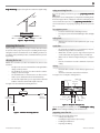
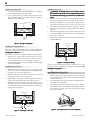
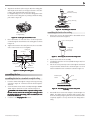
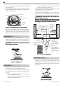
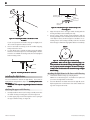
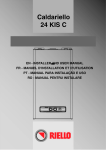
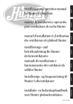
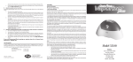
1
© 2003 Hunter Fan Company
41847-01 04/21/2003
2
®
If you need help installing the fan, your Hunter fan dealer can direct you to a licensed installer or electrician.
gathering the tools
Your new Hunter® ceiling fan is an addition to your home or office
that will provide comfort and performance for many years. This
installation and operation manual gives you complete instructions
for installing and operating your fan.
We are proud of our work. We appreciate the opportunity to supply you with the best ceiling fan available anywhere in the world.
Before installing your fan, record the following information for your
records and warranty assistance. Please refer to the carton and the
Hunter nameplate label (located on the top of the fan motor housing) for the proper information.
Model Name: __________________________
Catalog/Model No.: ______________
Serial No.: _____________________
Date Purchased: ___ / ___ / ______
Where Purchased: _______________________________
Please also attach your receipt or a copy of your receipt for reference.
cautions and warnings
•
•
•
•
•
•
•
•
Read een
ntir
o ok l et ccaare full
in
iree bbo
ullyy bbee fore bbeeg inn
innin
ingg in
insst all ati on. SSaave tth
he s e in
insstruc ti ons .
Us
nl
un
Usee oonl
nlyy H
Hun
untter rreep l acement p
paar t s .
To rree du
he rrii sk ooff p
jur
he ffaan
ducce tth
peers onal in
injur
juryy, aattt ach tth
din
he bbuil
uil
he ssup
up
p or t ssttruc tur
dir
o tth
uildin
dingg aaccuree ooff tth
upp
diree c tly tto
nl
he hhaardnd uuss e oonl
o tth
hes e in
cordin
nlyy tth
inss tr ucti ons , aan
dingg tto
up
p lilieed.
w are ssup
upp
To aavv o id p
os sib
ho ck , bbee fore in
po
sibll e eell e c tri c al ssh
inss t allin
llingg
y our ffaan, di
he p
ow er bbyy ttur
ur
n in
he ccir
ir
diss conn
nneec t tth
po
urn
ingg ooff f tth
ir-cui
o tth
he oou
utl et bbo
ox aan
nd aass s o ci ate d w
uitt bbrreaker s tto
waall
s wi tch llo
o c ati on. IIff yyo
ou ccaann
ot llo
o ck tth
he ccir
ir
nno
irccui
uitt bbrreaker s in tth
h e ooff f p
osi
po
sitti on, ssee cur
ureely ffaas ten a p
prromin
ineent
w ar nin
uch aass a ttaag , tto
o tth
he sseer vi ce p
ingg d
deev ice , ssu
paanel.
All w
ir
in
nd
wir
irin
ingg mu
muss t bbee in aacccordance w
wii th n
naati onal aan
l o c al eell e c tri c al cco
o des aan
nd A
NSI/N
o u aarre
AN
I/NFF PA 70. IIff yyo
un
ir
in
ou ssh
houl
d uuss e a qqu
ualiliff i ed eelle cunff amili
iliaar w
wiith w
wir
irin
ingg , yyo
uld
t r i ci a n .
To rree du
he rrii sk ooff p
jur
on
ot bbeend tth
he
ducce tth
peer s onal in
injur
juryy, d
do
no
b l ad e aatttachm
hen in
hmeent ssyy stem w
wh
insst allin
llingg , bbaal ancin
ingg ,
or ccll eanin
he ffaan . N
oreig n oob
b j ec t s bbeeingg tth
Neev er in
inss er t ffo
t we en rro
o tatin
ingg ffaan bbll ad es .
To rree du
he rrii sk ooff ffir
ir
ho ck , oorr m
o to r
ducce tth
iree , eell e c tr ic al ssh
mo
d am a g e , d
on
ot uuss e a sso
o liliddp e e d cco
o n tr o l w
do
no
d-sst ate ssp
wiith
thi s ffaan . Us
nl
un
p e e d cco
o n tr o l s .
Usee oonl
nlyy H
Hun
untter ssp
Ceilin
in
imum ooff 9 ffeeet ffo
or sstt anilingg hheei ght mu
musst bbee a m
min
inimum
d ar d m
o un
mo
unttin
ingg .
You will need the following tools for installing the fan:
• Electric drill with 9/64" bit
• Standard screwdriver
• Phillips-head screwdriver
• Wrench or pliers
considering optional accessories
Consider using Hunter’s optional accessories, including a wallmounted or remote speed control. To install and use the accessories, follow the instructions included with each product. For quiet
and optimum performance of your Hunter fan, use only Hunter
speed controls.
checking your fan parts
Carefully unpack your fan to avoid damage to the fan parts. Check
for any shipping damage to the motor or fan blades. If one of the
fan blades was damaged in shipment, return all the blades for replacement.
NOTE: If you are installing more than one fan, keep the fan blades
in sets, as they were shipped.
If any parts are missing or damaged, contact your Hunter dealer or
call Hunter Parts Department at 888-830-1326.
®
understanding Installer’s Choice
This patented 3-position mounting system provides you maximum
installation flexibility and ease. You can install your Hunter fan in
one of three ways. The steps in this manual include specific instructions for the fan mounting method of your choice. For a ceiling 8
feet or higher, standard mounting is recommended.
oun
Flu
ingg (Figure 1) fits close to the ceiling, for low ceilings
lussh M
Mo
unttin
less than 8 feet high.
10”
Fi gur
lu
o un
uree 1 - FFlu
lussh m
mo
unttin
ingg
S t a n d a rd M
oun
Mo
unttin
ingg (Figure 2) hangs from the ceiling by a downrod
(included), for ceilings 8 feet or higher. For ceilings higher than 8
feet, you can purchase Hunter extension downrods. All Hunter
fans use sturdy 3/4" diameter pipe to assure stability and wobblefree performance.
getting ready
To install a ceiling fan, be sure you can do the following:
• Locate the ceiling joist or other suitable support in ceiling.
• Drill holes for and install wood screws.
• Identify and connect electrical wires.
• Lift 40 pounds.
41847-01 04/21/2003
12”
Figur
o un
uree 2 - SStt a nd ard m
mo
untt in
ingg
© 2003 Hunter Fan Company
3
Angl e M
oun
Mo
unttin
ingg (Figure 3) hangs from a vaulted or angled ceiling.
using an existing fan site
If you are preparing a new fan site, go to the p rep arin
ingg a n
neew ffaan
sitte section.
si
If you plan to use an existing fan site, complete the following checklist for the support brace, ceiling hole, outlet box, and wiring. If you
ingg a n
nee w ffaan si
sitte seccannot check off every item, see the prep ar in
tion for instructions on properly preparing the site for your new
fan.
34º Max
8
Pitch
12
fan support system
•
•
Fan must attach directly to building structure.
Fan support system must hold full weight of fan and light
kit.
ceiling hole
Fi gur
ngl e m
o un
uree 3 - A
An
mo
unttin
ingg
•
preparing the fan site
outlet box
These guidelines are designed to help you select the best location
for your fan and to prepare the site prior to installing the fan. Proper
ceiling fan location and attachment to the building structure are
essential for safety, reliable operation, maximum efficiency, and energy savings.
choosing the fan site
Within the room where you want to install the fan, choose a fan
site where:
• No object can come in contact with the rotating fan blades
during normal operation.
• The fan blades are at least 7 feet above the floor and the
ceiling is at least 8 feet high.
• The fan blades have no obstructions to air flow, such as
walls or posts, within 30 inches of the fan blade tips.
• The fan is directly below a joist or support brace that will
hold the outlet box and the full weight of the fan.
See Figure 4 for the minimum mounting distances.
30” From
Wall or
Nearest
Obstruction
8’ Minimum
Ceiling Height
7’ Minimum
to Floor
Outlet box clearance hole directly below the joist or support brace.
•
•
•
•
UL-approved octagonal 4" x 1-1/2" outlet box (or as specified by the support brace manufacturer).
Outlet box secured to joist or support brace by wood
screws and washers through inner holes of outlet box.
Outer holes of outlet box aligned with joist or support
brace.
Bottom of outlet box recessed a minimum of 1/16" into
ceiling.
wiring
•
Electrical cable secured to outlet box by approved connector.
• Six inches of lead wires extend from outlet box.
See Figure 5 for an adequate existing fan site.
Support Brace
Ceiling Joist
Approved
Connector
Washer
Wood Screw
Ceiling
Outlet Box
Fi gur
d e qu ate ex
uree 5 - A
Ad
exiis tin
ingg ffaan si
sitte
he cceeilin
If your existing fan site is suitable, go to the in
inss t allin
llingg tth
ilingg
p l ate section and begin installing your new Hunter fan.
Fi gur
in
imum m
oun
uree 4 - M
Min
inimum
mo
unttin
ingg di
diss ta nce s
preparing a new fan site
To prepare the fan site follow four steps:
• Cutting the Ceiling Hole
• Installing the Support Brace (if necessary)
• Installing the Outlet Box
• Preparing the Wiring
© 2003 Hunter Fan Company
41847-01 04/21/2003
4
cutting the ceiling hole
1.
2.
preparing the wiring
Locate the site for the hole directly below the joist or support
brace that will hold the outlet box and fan.
Cut a 4" diameter hole through the drywall or plaster of the
ceiling as shown in Figure 6. You will use the hole to install the
support brace and outlet box.
1.
Ceiling Joist
Support Brace
2.
3.
4”
Diameter
Ceiling
Hole
Ceiling
4.
C AUTIO N: A
ll w
ir
in
aAll
wir
irin
ingg mu
muss t bbee in aacccord ance w
wiith n
nan d llo
o c al eell e c tr i c al cco
o de s aan
nd A
NSI/N
tio nal aan
AN
I/NFFPA 70. IIff yyo
ou
are un
ir
in
ou ssh
houl
d uuss e a qqu
ualiliff i e d eell ecunff amili
iliaar w
wiith w
wir
irin
ingg , yyo
uld
t r i ci a n .
Make sure the circuit breakers to the fan supply line leads and
associated wall switch location are turned off. If you cannot
lock the circuit breakers in the off position, securely fasten a
prominent warning device, such as a tag, to the service panel.
Thread the fan supply line through the outlet box so that the
fan supply line extends at least 6" beyond the box as shown in
Figure 8.
Attach the fan supply line to the outlet box with an approved
connector, available at any hardware store or electrical supply
house. Refer to Figure 8.
Make certain the wiring meets all national and local standards
and ANSI/NFPA 70.
Fi gur
uttin
he cceeilin
ole
uree 6 - C
Cu
ingg tth
ilingg hho
Approved
Connector
installing the support brace
If there is a ceiling joist directly above the hole which will allow the
outlet box to be recessed a minimum of 1/16" in the ceiling, go to
in
he oou
utl et bbo
ox section.
insst allin
llingg tth
If there is not an adequate ceiling joist available, do the following:
1. Attach a 2" x 4" support brace between two joists. The support brace must allow the bottom of the outlet box to be recessed a minimum of 1/16" into the ceiling. See Figure 7.
2. Check the support brace to ensure it will support the full weight
of the fan and light kit.
installing the outlet box
1.
2.
3.
4.
Obtain a UL-approved octagonal 4" x 1-1/2" outlet box, plus
two #8 x 1-1/2" wood screws and washers, available from any
hardware store or electrical supply house.
Orient the outlet box so that both the inner and outer holes in
the box align with the joist or support brace.
Drill pilot holes no larger than the minor diameter of the wood
screws (5/64") through the inner holes of the outlet box.
Attach the outlet box directly to the support brace or joist
with two #8 x 1-1/2" wood screws and washers. The bottom of
the outlet box must be recessed a minimum of 1/16" into the
ceiling as shown in Figure 7.
Support Brace
Washer
Wood Screw
Fi gur
he w
ir
in
uree 8 - Pr
Preep arin
ingg tth
wir
irin
ingg
You have now successfully prepared your ceiling fan site. For instructions on how to install your ceiling fan, continue with the inst allin
he cceeilin
llingg tth
ilingg p
pll ate section.
installing the ceiling plate
1.
2.
3.
Drill two pilot holes into the wood support structure through
the outermost holes on the outlet box. The pilot holes should
be 9/64" in diameter.
Thread the lead wires from the outlet box through the hole in
the middle of the ceiling plate.
Your fan comes with four neoprene noise isolators. Position
the isolators between the ceiling plate and ceiling by inserting
the raised areas on each isolator into the holes in the ceiling
plate. Refer to Figure 9.
Isolators
Outlet Box
1/16” Recess
Figur
nst allin
he oou
utl et bbo
ox
uree 7 - IIn
llingg tth
41847-01 04/21/2003
Wire Leads
Ceiling Plate
Figur
n s er t in
he iiss o lator s in
he cceeilin
uree 9 - IIn
ingg tth
intto tth
ilingg p
pllate
© 2003 Hunter Fan Company
5
4.
Align the slotted holes (refer to Figure 10) in the ceiling plate
with the pilot holes in the wood support structure. Note: The
isolation pads should be flush against the ceiling.
For Angled Ceilings: Be sure to orient the ceiling plate so that
the arrows on the ceiling plate are pointing towards the ceiling
peak. Refer to Figure 10.
Hanger Ball/
Downrod Assembly
Canopy
Canopy Trim Ring
Slots
Set Screw
Fi gur
lin
he ddo
ow nr
od
uree 12 - A
Asss emb
mblin
lingg tth
nro
assembling the fan for a low ceiling
Arrows for Orienting
on Angled Ceiling
1.
Fi gur
o catin
h e ssll ot te d hho
o l es tto
o uuss e
uree 10 - LLo
ingg tth
5.
6.
Place a flat washer on each of the two 3" screws and pass the
screws through the slotted holes in the ceiling plate as shown
in Figure 11.
Tighten the screws into the 9/64" pilot holes; do not use lubricants on the screws. Do not overtighten.
Remove the screw on the hanger ball to disassemble it from
the downrod as shown in Figure 13.
Screw on the Hanger Ball
Hanger Ball/
Downrod
Assembly
Ceiling Joist
2 x 4 Brace
Figur
he ssccrew ffrrom tth
he hhaa nger bbaall
uree 13 - R
Reemov in
ingg tth
2.
3.
Ceiling Plate
Flat Washer
Ceiling
Outlet Box
4.
3” Wood Screw
Remove the hook from the assembly.
Completely remove the set screw (identified in Figure 12) from
the fan adapter.
Put the set screw, previously removed, through the two black
neoprene washers and the hook as shown in Figure 14. Hook
must be installed in same orientation as shown in Figure 14.
Fi gur
nst allin
he cceeilin
uree 11 - IIn
llingg tth
ilingg p
pllate
assembling the fan
Black Neoprene
Washer
assembling the fan for a standard or angled ceiling
1.
2.
3.
Insert the downrod through the canopy and canopy trim ring
as shown in Figure 12. Feed wires from the fan through the
downrod.
Screw the downrod into the fan assembly until tight. IMPORTANT! Tighten downrod set screw as shown in Figure 12.
C AUTIO N: T
he ddo
ow nr
o d hhaa s a ssp
p e ci al cco
oatin
n tth
he
Th
nro
ingg oon
his cco
oatin
g; tth
he cco
oatin
thr
on
ot rreemove tth
ing;
ingg p
prre vent s
hree ads . D
Do
no
the ddo
ow nr
o d ffrrom un
nce aass s emb
on
ot
nro
unss c rew in
ingg . O
On
mbll e d, ddo
no
remov e tth
he d
ow nr
o d.
do
nro
he ffaan section.
ingg tth
Continue to the han gin
© 2003 Hunter Fan Company
Hook
Set Screw
Fi gur
lin
h e sseet ssccrew ffo
or llo
ow p
uree 14 - A
Asss emb
mblin
lingg tth
prrof ililee
a s s emb
mbll y
5.
Reassemble the set screw to the adapter as shown in Figure 14.
NOTE: The rubber washers should be tight enough to keep
the hook standing straight up, but the set screw should not be
completely tighten as to keep the hook from being able to
swing.
41847-01 04/21/2003
6
6.
7.
•
Place the canopy trim ring then the canopy over the adapter
as shown in Figure 15.
Place the low profile washer (lip up) into the canopy as shown
in Figure 15 fitting the notch in the low profile washer over the
adapter set screw and hook.
3.
Low Profile Washer
Tab Hole
Canopy
Canopy Trim Ring
Arrow on the
Low Profile
Washer
(Note: Wall
Wall Switch Wire for Separate switch must be
acceptable as a
Control of Light Fixture
general-use
Power
switch.)
Black
Wires
in
White
Ceiling
Bare or Green
Fi gur
lin
or llo
ow p
oun
uree 15 - A
Ass s emb
mblin
lingg ccaa no py ffo
prro f ililee m
mo
unttin
ingg
8.
9.
control the light with one wall switch and the fan with
another (two wall switches required).
Use connection 2, as described in Figure 17, if there is no separate wall switch power wire for the light fixture.
NOTE: Wall switches not included.
Connect the wires as shown in Figure 17. To connect the wires,
twist the bare metal leads together. Place a wire nut over the
intertwined length of wire and twist clockwise until tight as.
C AUTIO N: BBee ssur
ur
o bbaare w
ir
ir
uree n
no
wir
iree oorr w
wir
iree ssttr ands aarre vviis o nn
ib
ibll e aaffter m
maakin
ingg cco
nnee c tio ns .
All w
ir
in
nd llo
o c al
wir
irin
ingg mu
musst bbee in aacccord ance w
wiith n
naatio nal aan
el e c tr i c al cco
o de s aan
nd A
NSI/N
ou aarre un
AN
I/NFF PA 70. IIff yyo
unff amili
iliaar
d uuss e a qqu
ualiliff i e d eell e c tri ci an.
w ith w
ir
in
ou ssh
houl
wir
irin
ingg , yyo
uld
Rotate the canopy until the arrow on the low profile washer
aligns with the tab hole on the canopy as shown in Figure 15.
Align the holes in the low profile washer with the holes in the
adapter and assemble securely with the three #8-32 x 1” screws.
2 x 4 Brace
Outlet Box
hanging the fan
Raise the fan and place the hook through the loop on the ceiling plate as shown in Figure 16. Use the note and arrow engraved in the ceiling plate to assist in determining the direction to assemble.
WAR N IN G: FFaan m
o t aasss emb
maay ffaall iiff n
no
mbll ed aass dir
diree c ted in
thes e in
insst allllaati on in
insstruc tio ns .
Hook
Ceiling Plate
Approved
Connectors
Green Ground Wire from
Hanger Pipe (not present
with flush mounting
option)
Loop
White
Black
1.
Connections:
1
1. Connect Blk/Wht
2
wire from the fan to the
wall switch for separate
Blk/Wht
control of the light
3 Wires
fixture, or
from Fan 2. Connect Blk/Wht
wire from the fan to the
ceiling black wire if there
is no separate wall
switch wire for the light
fixture.
Figur
ir
in
he ffaa n
uree 17 - W
Wir
irin
ingg tth
installing the canopy
1.
Fi gur
ngin
h e ffaan
uree 16 - Ha
Han
ingg tth
wiring the fan
1.
2.
Rotate the fan 180º clockwise from the initial position when
hanging the fan. The arrows on the hanger ball and on the
ceiling plate should be pointing in the same direction and
should be pointing towards the tab hole on the canopy. Refer
to Figure 18.
Disconnect the power by turning off the circuit breakers to
the outlet box and associated wall switch location.
You can use either one or two wall switches to control the fan
and/or lights separately. Use connection 1, as described in Figure 17, to
• control the light with a wall switch and the fan with a pull
chain (one wall switch required),
• control the light with a pull chain and the fan with a wall
switch (one wall switch required), or
Fi gur
o t atin
h e ffaan
uree 18 - R
Ro
ingg tth
41847-01 04/21/2003
© 2003 Hunter Fan Company
7
2.
3.
For Flush Mounting: The arrows on the low profile washer and
on the ceiling plate should be pointing in the same direction
and should be pointing towards the tab hole on the canopy.
Hook the tab hole over the tab on the ceiling plate as shown in
Figure 19.
Raise the canopy, be sure the holes in the canopy and the ceiling plate are aligned, and loosely assemble the canopy screws
one at a time. When all three screws are assembled, securely
tighten all three canopy screws. Refer to Figure 19.
assembling the blades
Hunter fans use several styles of fan blade irons (brackets that hold
the blade to the fan).
1. Your fan may include blade grommets. If your fan has grommets, insert them by hand into the holes on the blades as shown
in Figure 22.
Grommet
Tab Hole
and Tab
Fan Blade
Canopy
Screw
Fi gur
nst allin
he ccaan opy
uree 19 - IIn
llingg tth
installing the canopy trim ring
1.
Fi gur
ns er tin
he ggrro mm
he ffaa n bbll ad e s
uree 22 - IIn
ingg tth
mmeet s in
intto tth
To easily install the canopy trim ring, locate the two tabs on
the canopy trim ring. See Figure 20.
2.
Attach each blade to blade iron using three blade assembly
screws as shown in Figure 23. Some fans feature a decorative
medallion as well as a blade iron. Insert the assembly screws
into the blade iron, through the blade and into the medallion,
with the blade sandwiched between the blade iron and medallion as shown in Figure 24.
Canopy
Press Here when
Removing
Press Here when
Removing
Canopy
Trim Ring
Tab
Fi gur
in
uree 20 - C
Caan opy ttrr im rrin
ingg
2.
3.
Take both hands and push the canopy trim ring up to the top
of the canopy. See Figure 20.
The canopy trim ring will snap and lock into place on the
canopy.
removing the canopy trim ring
1.
2.
Locate the tab indicators, small bumps on top of tabs. Refer to
Figure 21.
To remove the canopy trim ring, press firmly on opposite sides
of the ring towards the canopy as shown in Figure 21. The tabs
will flex out releasing the trim ring from the canopy.
Tab Indicator
Fi gur
h e bblla d e tto
o tth
he bbll ad e ir
on
uree 23 - A
Attt achin
ingg tth
iro
Canopy Trim Ring
Canopy
Fi gur
h e ccaan o py ttrr im rrin
in
uree 21 - R
Reemov in
ingg tth
ingg
© 2003 Hunter Fan Company
41847-01 04/21/2003
8
Switch Housing
Mounting Plate
Blade Iron
Housing
Assembly
Screw
Upper Plug
Connector
Upper Switch
Housing
Fi gur
he up
p er ssw
wi tch hho
ou sin
o tth
he
uree 26 - A
Attt ach in
ingg tth
upp
singg tto
moun
unttin
ingg p
pllate
Medallion
3.
4.
Fi gur
he bbll ad e tto
o tth
he bbll ad e ir
o n aan
nd
uree 24 - A
Attt ach in
ingg tth
iro
me d alli
on
llio
3.
4.
If you used grommets, the blades may appear slightly loose
after screws are tightened. This is normal.
Remove the blade mounting screws and rubber shipping
bumpers from the motor.
For each blade, insert one blade mounting screw through the
blade iron as shown in Figure 25, and attach lightly to the fan.
Insert the second blade mounting screw, then securely tighten
both mounting screws.
Align the keyhole slots in the upper switch housing with the
housing assembly screws installed previously.
Turn the upper switch housing counterclockwise until the
housing assembly screws are firmly situated in the narrow end
of the keyhole slots as shown in Figure 27. Install the one remaining #6-32 x 3/8" housing assembly screw into the third
hole in the upper switch housing. Tighten all three screws firmly.
Fi gur
oun
he up
p er ssw
witch hho
ou sin
uree 27 - M
Mo
unttin
ingg tth
upp
singg
C AUTIO N: M
ur
he up
p er ssw
wi tch hho
ousin
eMaake ssur
uree tth
upp
singg iiss sseousin
oun
cur
o tth
he ssw
w itch hho
pllate . FFaailsingg m
mo
unttin
ingg p
ureely aattt ached tto
ur
op
nd ttii ghten aall
ll tthr
hr
ousin
uree tto
prro p er ly aatttach aan
hree e hho
singg aass s emb
o ul
d rree s ul
he ssw
w itch hho
ou sin
nd liligght
mbll y ssccrew s cco
uld
ultt in tth
singg aan
f i xtur
llingg .
uree ffaallin
Fi gur
he bbll ad e ir
on tto
o tth
he ffaa n
uree 25 - A
Attt achin
ingg tth
iro
installing the light fixture
You can install with or without the light fixture. If you want to
he
install without the light fixture, skip to the in
insst allin
llingg w
wiithout tth
liligght ffiixtur
uree section.
WAR N IN G: Us
nl
he ssup
up
p liliee d liligght ffii xtur
or tth
his ffaan
Usee oonl
nlyy tth
upp
uree ffo
mo d el.
attaching the light fixture to the lower switch housing
1.
2.
Uninstall the switch housing cap and plug button.
NOTE: Do not discard any parts. You will need to replace it if
you remove the light fixture in the future.
Insert the black wire and white wire from the light kit assembly through the hole in the bottom of the lower switch housing. Refer to Figures 28 and 29.
attaching the upper switch housing
1.
2.
Partially install two #6-32 x 3/8" housing assembly screws into
the switch housing mounting plate as shown in Figure 26.
Feed the upper plug connector through the center opening of
the upper switch housing. See Figure 26.
41847-01 04/21/2003
© 2003 Hunter Fan Company
9
Upper Switch
Housing
Lower Switch
Housing
Lower Plug
Connector
Upper Plug
Connector
Housing
Assembly
Screw
Light Fixture
Lower
Switch
Housing
Fi gur
o nn
he p
lu
onn
uree 30 - C
Co
nneec t in
ingg tth
plu
lugg cco
nneec to rs
2.
Fi gur
lin
h e liligght ffii xtur
uree 28 - A
Asss emb
mblin
lingg tth
uree
3.
Securely tighten the light kit assembly into the bottom of the
lower switch housing. Refer to Figure 29.
Place the lower switch housing assembly over the upper switch
housing. Align the side screw holes in the upper and lower
switch housings. Attach the lower switch housing to the upper switch housing with three #6-32 x 3/8" housing assembly
screws. See Figure 30.
installing the glass bowl
Refer to Figure 31.
1. Install two max 60 Watt medium base incandescent bulbs.
2. Attach the extra pull chain (included in the sack parts) to the
fan pull chain using the plastic breakaway connector.
3. Thread the fan pull chain through the hole in the metal disk.
Then, thread the fan pull chain through the small hole beside
the hole in the center of the glass bowl.
4. Thread the light pull chain through the hole in the center of
the glass bowl.
5. Place the cover plate up against the glass bowl. Align the holes
in the cover plate and glass bowl.
6. Thread the fan pull chain and light pull chain through the appropriate holes.
7. Thread the light pull chain through the finial and screw the
finial onto the threaded rod end until tight.
Figur
uree 29 - A
Attt ach ed liligght ffiix tur
uree
4.
5.
Install the nut and washer onto the end of the light kit assembly inside of the lower switch housing. Securely tighten the
nut and washer. Insert and tighten the two #6-32 sems light
fixture mounting screws. Refer to Figure 29.
Using the wire nuts on the two light kit wires in the lower switch
housing, connect the black wire from the light kit assembly to
the black/white wire from the lower switch housing and connect the white wire from the light kit assembly to the white
wire from the lower switch housing.
Fan Pull Chain
Glass Bowl
Lower Switch
Housing
Threaded Rod
Metal Disk
Light Pull Chain
attaching the lower switch housing
1.
Connect the upper plug connector from the motor to the lower
plug connector in the lower switch housing assembly. See Figure 30.
NOTE: Both plug connectors are polarized and will only fit together one way. Make sure that both connectors are properly
aligned before connecting them together. Incorrect connection could cause improper operation and damage to the product.
© 2003 Hunter Fan Company
Cover Plate
Finial
Fi gur
ns ta llin
he ggll as s bbo
owl
uree 31 - IIn
llingg tth
41847-01 04/21/2003
10
installing without the light fixture
operating your ceiling fan
Your Hunter fan comes with an integrated light fixture assembly
and an optional switch housing cap and plug button. This feature
gives you the option of installing the fan with or without the included light fixture.
1.
2.
attaching the upper switch housing
1.
2.
3.
4.
Partially install two #6-32 x 3/8" housing assembly screws into
the switch housing mounting plate as shown in Figure 26.
Feed the upper plug connector through the center opening of
the upper switch housing. See Figure 26.
Align the keyhole slots in the upper switch housing with the
housing assembly screws installed previously.
Turn the upper switch housing counterclockwise until the
housing assembly screws are firmly situated in the narrow end
of the keyhole slots as shown in Figure 27. Install the one remaining #6-32 x 3/8" housing assembly screw into the third
hole in the upper switch housing. Tighten all three screws firmly.
C AUTI O N: M
ur
he up
p er ssw
wi tch hho
ousin
eMaake ssur
uree tth
upp
singg iiss sseousin
oun
cur
o tth
he ssw
w itch hho
pllate . FFaailsingg m
mo
unttin
ingg p
ureely aattt ached tto
ur
op
nd ttii ghten aall
ll tthr
hr
ousin
uree tto
prrop er ly aatttach aan
hree e hho
singg aass s emb
o ul
d rree s ul
he ssw
w i tch hho
ou sin
nd liligght
mbll y sscc rew s cco
uld
ultt in tth
singg aan
f ixtur
llingg .
uree ffaallin
3.
4.
Turn on electrical power to the fan.
The fan pull chain controls power to the fan. The pull chain
has four settings in sequence: High, Medium, Low and Off.
• Pull the chain slowly to change settings.
• Release slowly to prevent the chain from recoiling into the
blades.
• The chain uses a breakaway connector that separates if
the chain is jerked. If this happens, simply reinsert the chain
into the connector.
The light pull chain controls power to the light. The pull chain
has two settings: On and Off.
Ceiling fans work best by blowing air downward (counterclockwise blade rotation) in warm weather to cool the room with a
direct breeze. In winter, having the fan draw air upward (clockwise blade rotation) will distribute the warmer air trapped at
the ceiling around the room without causing a draft. Refer to
Figure 32.
attaching the lower switch housing
1.
2.
Connect the upper plug connector from the motor to the lower
plug connector in the lower switch housing assembly. See Figure 30.
NOTE: Both plug connectors are polarized and will only fit together one way. Make sure that both connectors are properly
aligned before connecting them together. Incorrect connection could cause improper operation and damage to the product.
Place the lower switch housing assembly over the upper switch
housing. Align the side screw holes in the upper and lower
switch housings. Attach the lower switch housing to the upper switch housing with three #6-32 x 3/8" housing assembly
screws. See Figure 30.
Fi gur
ir ffll o w p
uree 32 - A
Air
paatter ns
To change the direction of air flow, turn the fan off and let it
come to a complete stop. Slide the reversing switch on the fan
to the opposite position as shown in Figure 33. Restart fan.
Fan Pull
Chain
Reversing
Switch
Fi gur
ull cch
hain aan
n d rreev ersin
w i tc h
uree 33 - PPull
singg ssw
41847-01 04/21/2003
© 2003 Hunter Fan Company
11
cleaning your ceiling fan
caring for finishes
For cleaning, a soft brush or lint-free cloth should be used to prevent scratching the finish. A vacuum cleaner brush nozzle can remove heavier dust. Surface smudges or an accumulation of dirt
and dust can easily be removed by using a mild detergent and a
slightly dampened cloth. An artistic agent may be used, but never
use abrasive cleaning agents as they will damage the finish.
caring for blades
Wicker blades should be cleaned with a damp cloth. Do not hang
this fan in outdoor conditions.
troubleshooting
Problem: Nothing happens; fan does not move.
1. Turn power on, replace fuse, or reset breaker.
2. Loosen canopy, check all connections according to the
wir
in
he ffaan section.
irin
ingg tth
3. Check the plug connection in the switch housing.
4. Push motor reversing switch firmly up or down to ensure
that the switch is engaged.
5. Pull the pull chain to ensure it is on.
6. Remove the shipping bumpers.
Problem: Noisy operation.
1. Tighten the blade bracket screws until snug.
2. Tighten the blade screws until snug.
3. Check to see if the blade is cracked. If so, replace all the
blades.
4. Change to an approved speed control.
5. Be sure that the glass is secure.
6. Check and tighten the screws in the switch housing
mounting plate and in the upper and lower switch housing.
Problem: Excessive wobbling.
1. If your fan wobbles when operating, use the enclosed balancing kit and instructions to balance the fan.
2. Tighten all blade and/or blade iron screws.
3. Turn power off, support fan very carefully, and check that
the hanger ball is properly seated.
If you need parts or service assistance, please call 888-830-1326 or
visit us at our WEB site at http://www.hunterfan.com.
Hunter Fan Company
2500 Frisco Avenue
Memphis, Tennessee 38114
© 2003 Hunter Fan Company
41847-01 04/21/2003