1
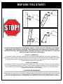
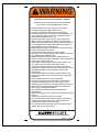
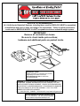
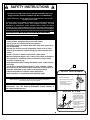
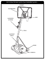
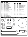
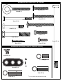
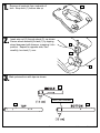
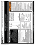
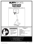
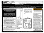
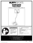
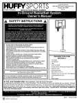
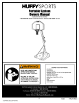
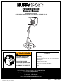
Portable System
Owners Manual
Customer Service Center
• N53 W24700 South Corporate Circle • Sussex, WI 53089 • U.S.A.
REQUIRED TOOLS AND
WARNING!
•
•
•
•
READ AND UNDERSTAND
OPERATOR'S MANUAL
BEFORE USING THIS UNIT.
•
•
•
•
•
•
•
FAILURE TO FOLLOW
OPERATING INSTRUCTIONS
COULD RESULT IN INJURY
OR DAMAGE TO PROPERTY.
MATERIALS:
Two People
Tape Measure
Wood Board (Scrap)
Wrenches: (Two) 7/16”, 1/2”, 9/16”, 3/4” or Large and Small
Adjustable Wrenches
Safety Goggles
Sawhorse or Support Table
Step Ladder 8 ft. (2.4 m)
Garden Hose or Sand (225 lb.) (102 kg)
Hammer
Tape
Phillips Head Screw Driver
Toll-Free Customer Service Number for U.S: 1-800-558-5234,
For Canada: 1-800-284-8339,
For Europe: 00 800 555 85234 (Sweden: 009 555 85234),
For Australia: 1-800-333 061
Internet Address: http://www.huffysports.com
1
© COPYRIGHT 2000 by HUFFY SPORTS
01/04
P/N 211954E
BEFORE YOU START!
To ensure optimal playability of backboard system, a close tolerance fit between the elevator
components and hardware is required. Test-fit large bolts into large holes of elevator tubes,
backboard brackets, and triangle plates. Carefully rock them in a circular motion to ream out
any excess paint from holes if necessary.
AVANT DE COMMENCER !
Pour garantir l'utilisation optimale du panneau, les composants du système élévateur et la visserie doivent être bien
ajustés (serrés). À titre d'essai, insérez les gros boulons dans les gros trous des tubes du système élévateur, des supports
du panneau et des plaques triangulaires. Basculez-les avec précaution en imprimant un mouvement circulaire pour
éliminer l'excédent de peinture, si nécessaire.
¡ANTES DE COMENZAR!
Para asegurar el óptimo rendimiento del sistema del respaldo en el juego, se requiere un ajuste de tolerancia estrecha
entre los componentes del elevador y el herraje. Pruebe el ajuste de los pernos grandes en los orificios grandes de los
tubos elevadores, soportes del respaldo y placas triangulares. Cuidadosamente muévalos en círculos para eliminar
cualquier exceso de pintura, si es necesario.
VORBEREITENDE MASSNAHMEN
Um sicherzustellen, dass das Korbwandsystem optimal für den Spielbetrieb geeignet ist, müssen die Komponenten der
Verlängerungsvorrichtung und die verschiedenen Befestigungsteile fest miteinander verschraubt werden. Große Schrauben
zur Probe in die großen Löcher der Verlängerungsrohre, Korbwandklammern und Dreiecksplatte stecken und diese
vorsichtig in einer Kreisbewegung hin- und herbewegen, um eventuelle Farbrückstände aus den Bohrungen zu entfernen.
P/N 211954E
01/04
2
WARNING
FAILURE TO FOLLOW THESE WARNINGS MAY RESULT
IN SERIOUS INJURY AND/OR PROPERTY DAMAGE.
Owner must ensure that all players know and follow
these rules for safe operation of the system.
• DO NOT HANG on the rim or any part of the system
including backboard, support braces or net.
• During play, especially when performing dunk type
activities, keep player's face away from the backboard, rim
and net. Serious injury could occur if teeth/face come in
contact with backboard, rim or net.
• Do not slide, climb, shake or play on base and/or pole.
• After assembly is complete, fill system completely with
water or sand and stake to the ground. Never leave system
in an upright position without filling base with weight, as
system may tip over causing injuries.
• When adjusting height or moving system, keep hands and
fingers away from moving parts.
• Do not allow children to move or adjust system.
• During play, do not wear jewelry (rings, watches, necklaces,
etc.). Objects may entangle in net.
• Surface beneath the base must be smooth and free of
gravel or other sharp objects. Punctures cause leakage and
could cause system to tip over.
• Keep organic material away from pole base. Grass, litter,
etc. could cause corrosion and/or deterioration.
• Check pole system for signs of corrosion (rust, pitting,
chipping) and repaint with exterior enamel paint. If rust has
penetrated through the steel anywhere, replace pole
immediately.
• Check system before each use for proper ballast, loose
hardware, excessive wear and signs corrosion and repair
before use.
• Check system before each use for instability.
• Do not use system during windy and/or severe weather
conditions; system may tip over. Place system in the
storage position and/or in an area protected from the wind
and free from personal property and/or overhead wires.
• Never play on damaged equipment.
• See instruction manual for proper installation and
maintenance.
• When moving system, use caution to keep mechanism from
shifting.
• Keep pole top covered with cap at all times.
• Do not allow water in tank to freeze. During sub-freezing
weather add non-toxic antifreeze, sand or empty tank
completely and store. (Do not use salt.)
• Use extreme caution if placing system on sloped surface.
System may tip over more easily.
In the U.S.:1-800-558-5234 and Canada: 1-800-284-8339
201241
3
2/99
01/04
P/N 211954E
NOTICE TO ASSEMBLERS
ALL Huffy Sports Basketball Systems, including those used for DISPLAYS, MUST be assembled
and ballasted with sand or water according to the instructions. Failure to follow instructions
could result in SERIOUS INJURY. It is NOT acceptable to devise a makeshift weight system.
IMPORTANT!
Remove all contents from boxes.
Be sure to check inside pole sections;
hardware and additional parts are packed inside.
WARRANTY CARD:
Please remember to complete your product
registration form either on-line at:
www.huffysports.com or mail-in the
enclosed postcard.
WARNING: IF YOUR SYSTEM IS EQUIPPED WITH AN ACRYLIC
BACKBOARD, EXAMINE BACKBOARD FOR ANY DAMAGE THAT MAY
HAVE OCCURRED DURING SHIPMENT. CRACKS IN THE BACKBOARD
COULD RESULT IN SUDDEN BREAKAGE. IF BACKBOARD IS DAMAGED
IN ANY WAY PRIOR TO OR AFTER ASSEMBLY, CALL TOLL-FREE
NUMBER FOR FREE REPLACEMENT:
U.S. 1-800-558-5234; CANADA: 1-800-284-8339; http://www.huffysports.com
For more information on assembly, placement, proper
use, and maintenance, visit The American Basketball
Council website at http://www.smarthoops.com.
P/N 211954E
01/04
4
SAFETY INSTRUCTIONS
FAILURE TO FOLLOW THESE SAFETY INSTRUCTIONS MAY RESULT IN
SERIOUS INJURY, PROPERTY DAMAGE AND WILL VOID WARRANTY.
Owner must ensure that all players know and follow these rules for safe
operation of the system.
To ensure safety, do not attempt to assemble this system without following
the instructions carefully. Proper and complete assembly, use and
supervision is essential for proper operation and to reduce the risk of
accident or injury. A high probability of serious injury exists if this system is
not installed, maintained, and operated properly. Check entire box and inside
all packing material for parts and/or additional instructional material. Before
beginning assembly, read the instructions and identify parts using the
hardware identifier and parts list in this document.
• If using a ladder during assembly, use extreme caution.
• Two (2) people are recommended for this operation.
• Check base regularly for leakage. Slow leaks could cause system to tip
over unexpectedly.
• Seat the pole sections properly (if applicable). Failure to do so could
allow the pole sections to separate during play and/or transport of the
system.
• Climate, corrosion or misuse could result in system failure.
• Minimum operational height is 6'6" (1.98 m) to the bottom of backboard.
• This equipment is intended for home recreational use only and NOT
excessive competitive play.
• Read and understand the warning label affixed to pole. Label is shown
to the right.
• The life of your basketball pole depends on many conditions: climate,
placement of pole, the location of pole, exposure to corrosives such as
pesticides, herbicides or salts. These are all important factors.
• If technical assistance is required, contact Huffy Sports.
• Adult supervision is recommended when adjusting height.
54
HEIGHT ADJUSTMENT
TO ADJUST BACKBOARD:
Most injuries are caused by misuse and/or not following instructions.
Use caution when using this system.
1
3
1. While holding handle, remove pin.
2. Move elevator up or down to
desired height.
2
3. Replace pin full length to lock
system at desired height.
For more information on assembly, placement, proper use and
maintenance, visit The American Basketball Council website at
http://www.smarthoops.com.
2
MOVING SYSTEM
1. Adjust basketball backboard
height to lowest position.
1
2. While holding pole, rotate
basketball system forward
until wheels engage with
ground.
2
3
4
3. Move basketball system to
desired location.
4. Carefully rotate basketball
system upright.
5. Reattach ground restraint and
check system for stability.
201252
5
01/04
2/99
P/N 211954E
Get to know the basic parts of your basketball system.....
FRONT
BACKBOARD
RIM
ELEVATOR
SYSTEM
POLE
SUPPORT
STRUT
BASE
WHEELS
P/N 211954E
01/04
6
PARTS LIST - See Hardware Identifier
Item
Qty.
Part No.
Description
1
2
3
4
5
6
7
8
9
10
11
12
13
14
15
16
17
18
19
20
21
22
23
24
25
26
27
28
29
30
1
2
2
1
1
1
1
1
1
1
2
1
7
1
2
9*
1
2
4
4
4
2
2
2
1
1
1
1
1
2
206336
206330
226401
904847
908024
908487
202820
202822
202821
203063
906410
203220
203218
201625
203798
203100
204832
203231
203232
201124
206360
204858
204857
204859
203038
204850
204853
904833
204872
203103
Tank
Wheel Axle, 4-1/4 Long
Wheel, 4“ (Black)
Top Pole Section
Middle Pole Section
Bottom Pole Section
Rod, 3/8 O.D. x 4-3/4 Long
Eyebolt, 3/8-16 x 3-3/4 Long
Disk, 2-3/4 Diameter
Nylon Insert Lock Nut, 3/8-16
Strut, 43” Long, With Flat Ends
Nut, Ny-lock, 5/16-18
Washer, 5/16 Flat
Bolt,Yellow Dichromate, 5/16-18 X 3.60" Long
Bolt, Hex Flange, 5/16-18 x 1-1/2 Long
Hex Flange Nut 5/16-18
Bracket, Pole Mount
Carriage Bolt, 5/16-18 x 3-1/2 Long
Washer, Metal, 3/4” O.D.
Lock Nut, Hex Head, 3/8-16
Bolt, Hex Head, 3/8-16 x 2-5/8 Long
Spacer, Biscuit, Plastic
Spacer, Metal 1/2” O.D.x1.44 Long
Cover, Spring
Carriage Bolt, 5/16-18 x 2-3/4 Long
Pin, Locking
Lanyard, Black Coil
Height Adjustment Rod
Label, Height Indicator
Carriage Bolt, 5/16-18 x 2 Long
31
1
204803
Screw, Phillips Head
Item
Qty.
Part No.
Description
32
33
34
35
36
37
38
39
40
41
42
43
44
45
46
47
48
49
50
51
52
53
54
55
1
1
2
4
2
1
4
7
2
1
1
2
2
2
1
6
1
2
12
1
1
1
1
4*
204855
204856
900103
201683
200874
206990
201681
206340
904820
204837
Handle, Left
Handle, Right
Board Bracket
Spacer .530 I.D. x.63 O.D. x 1.50 Long
Spacer, Steel .402 I.D.x50 O.D.x1.5 L
Reinforcement Bracket
Spacer, Plastic, .530 I.D. x .875 Long
Lock Nut, Hex Head, 1/2-13
Elevator Tube, Lower - Long
Spring
Rim
Elevator Tube, Upper - Short
Spacer, .530 I.D. x 1.875 Long
Plate, Triangle, (Black)
Cap, Pole Top
Bolt, Hex, 1/2-13 x 8 Long
Bolt, Hex, 1/2-13 x 3-1/2 Long
Plug Cap
Smart Clip, Net Holder
Net
Anchor, T-strap
Stake, Tie Down
Label, Height Adjustment and Moving
Bolt, Hex Flange, 5/16-18 x 1 Long
904808
201682
900867
202814
206244
204870
203617
201219
201568
203124
201252
205528
* YOU MAY HAVE EXTRA PARTS WITH THIS MODEL.
HARDWARE IDENTIFIER (NUTS & WASHERS, STEEL RODS & STEEL SPACERS)
Item #20 (4)
Item #13 (7)
Item #39 (7)
Item #16 (9)*
Item #10 (1)
Item #12 (1)
Item #19 (4)
Item #9 (1)
Item #23 (2)
Item #2 (2)
Item #36 (2)
Item #7 (1)
7
01/04
P/N 211954E
HARDWARE IDENTIFIER (BOLTS & SCREWS)
Item #30 (2)
Item #8 (1)
Item #25 (1)
Item #14 (1)
Item #18 (2)
Item #21 (4)
Item #15 (2)
Item #48 (1)
Item #47 (6)
Item #55 (4)*
Item #31 (1)
HARDWARE IDENTIFIER (PLASTIC SPACERS & CLIPS)
Item #50 (12)
Item #38 (4)
Item #22 (2)
Item #35 (4)
Item #44 (2)
P/N 211954E
01/04
* You may have extra parts with this model.
8
1.
Remove all contents from underside of
tank. Keep tank (1) bottom side up
2.
1
Insert axle rod (2) through wheel (3), as shown.
Secure wheel assembly to tank (1) by tapping
wheel downward with hammer, snapping it into
position. Repeat for opposite side, then
carefully, turn tank (1) over.
3
2
1
3.
Mark pole sections with tape as shown.
5
TAPE (not included)
6
4
9
01/04
P/N 211954E
4.
IMPORTANT! Center alignment slot of
middle pole section (5) in a lower hole
of top pole section (4) as shown. While
maintaining alignment, bounce middle pole
(5) into top pole section (4) as shown until
top pole section no longer moves toward
taped reference mark on middle pole.
Upright assembly.
5
NOTE:
POLE SECTIONS
SHOULD HAVE A
3-1/2" (9 CM)
MINIMUM OVERLAP.
4
WOOD SCRAP
(NOT SUPPLIED)
5.
IMPORTANT! Center
alignment slot of lower pole
section (6) in a lower hole of
middle pole section (5) as in
step 3. While maintaining
alignment, bounce top & middle
pole assembly (4 & 5) onto
lower pole section (6) as shown
until top & middle pole assembly
no longer moves toward taped
reference mark on bottom pole.
4
5
NOTE:
POLE SECTIONS
SHOULD HAVE A
3-1/2" (9 CM)
MINIMUM OVERLAP.
6
WOOD SCRAP
(NOT SUPPLIED)
P/N 211954E
01/04
10
6.
Install rod (7) through holes in bottom pole
section (6) and eyebolt (8).
7
4
5
6
8
7.
Insert pole assembly into tank assembly as shown.
6
WARNING!
TWO PEOPLE REQUIRED
FOR THIS PROCEDURE.
FAILURE TO FOLLOW THIS
WARNING COULD RESULT
IN SERIOUS INJURY AND/OR
PROPERTY DAMAGE.
7
8
IMPORTANT!:
DO NOT OVER
TIGHTEN
8.
Carefully place unit on its side. Secure pole
bottom (6) to tank with anchor strap (52),
washers (9 & 13) and nut (10) as shown.
Upright unit.
NOTE:
6
Keep unnecessary pressure
off of the pole assembly when
in this position. Two people
recommended for this
procedure.
9
13
10
1
52
IMPORTANT!:
DO NOT OVER
TIGHTEN
11
01/04
P/N 211954E
9.
Secure strut tubes (11) to bottom pole
section (6) as shown.
WARNING!
11
6
13
14
12
TIGHTEN BOLT (14) IN
LOCK NUT (12) UNTIL
FLUSH (EVEN) WITH LOCK
NUT’S OUTER EDGE.
11
1
10.
13
11.
Carefully place unit in the side position and
secure strut (11) to tank (1) as shown.
Completely tighten. Repeat for opposite
side. Upright unit.
Install pole mount bracket (17) and
reinforcement bracket (37) with carriage
bolts (18) as shown. Tighten flange nuts
(16) completely.
NOTE:
Keep unnecessary pressure
off of the pole assembly when
in this position. Two people
recommended for this
procedure.
37
15
1
4
13
13
18
11
16
16
16
1
P/N 211954E
18
01/04
12
17
12.
Attach spacers (22, 23) to pole mount bracket (17) with bolts (21), washers (19), and
nuts (20) as shown.
IMPORTANT!:
Tighten just until
washers (19) stop
moving.
17
22
20
23
19
20
19
21
19
23
19
22
13.
21
Assemble lanyard (27) to locking pin (26) as shown (FIG A). Attach covers (24) onto
pole mount bracket (17) with carriage bolt (25) and nut (16) as shown.
FIG. A
16
24
17
24
IMPORTANT!:
25
27
26
Loop end of pin
lanyard (27) over
carriage bolt (25)
as it passes
through the pole
mount bracket
(17) during this
assembly.
13
25
27
26
01/04
P/N 211954E
14.
Apply logo and height indicator labels (29) to
adjustment rod (28) as shown. Attach handle
parts (32, 33) to adjustment rod with screw
(31), carriage bolt (30), and flange nut (16) as
shown.
15.
Insert handle assembly through pole
mount assembly as shown. Lock
pole assembly in place at the 10’
(3.05 m) mark with pin (26).
IMPORTANT!:
Indicator labels
should be applied
as close to holes
as possible to
prevent labels from
being damaged
during height
adjustment.
28
26
29
28
16
30
16
31
30
P/N 211954E
01/04
14
16.
Attach backboard support brackets (34) to the backboard frame using bolts (21),
spacers (36), and nuts (20) as shown.
36
20
36
20
21
34
21
15
01/04
P/N 211954E
17.
Attach rim to board as shown. For spring loaded rim assembly, refer to instructions
included with rim hardware. Assemble lower elevator tubes (40) as shown. DO NOT
overtighten.
16
34
39
57
57
47
41
40
40
42
55
IMPORTANT!:
IMPORTANT!:
Refer to instructions
included with board and rim
hardware for backboard and
rim assembly.
It is necessary for all
parts to be installed for
this mechanism to work
safely and properly.
P/N 211954E
01/04
16
18.
Assemble upper elevator tubes (43) to backboard brackets (34). DO NOT overtighten.
39
35
34
43
35
47
40
43
19.
Support pole on sawhorse. Attach backboard
assembly to top pole section (4) as shown.
Install pole cap (46).
WARNING!
USE CAUTION; ELEVATOR
ASSEMBLY IS HEAVY.
IMPORTANT!:
TWO PEOPLE REQUIRED FOR
THIS PROCEDURE. FAILURE TO
FOLLOW THIS WARNING
COULD RESULT IN SERIOUS
INJURY AND/OR PROPERTY
DAMAGE.
DO NOT OVER
TIGHTEN
NOTE: STEP 5
COMPLETED ASSEMBLY:
39
40
38
4
45
46
45
38
40
40
47
48
SAWHORSE OR SUPPORT TABLE
17
01/04
P/N 211954E
20
Install upper elevator tubes (43) to triangle plates (45) as shown. Then, install handle
assembly to lower elevator tubes (40) using bolt (47), spacers (44), and nut (39) as
shown.
39
43
38
40
NOTE:
Before going on to
next step, set
adjustable system
assembly to the 10’
(3.05 m) setting.
45
40
38
IMPORTANT!:
47
DO NOT OVER
TIGHTEN
43
28
44
21.
44
Install handle assembly to lower
elevator tubes (40) using bolt (47),
spacers (44), and nut (39) as shown.
47
P/N 211954E
01/04
18
39
22.
Insert bolt (47) through left side upper elevator tube (43), then
stretch spring (41) onto bolt (47). Insert bolt (47) through right
side upper elevator tube (43) and secure with nut (39).
43
39
47
41
43
WARNING!
USE EYE PROTECTION
WHEN INSTALLING
SPRINGS.
23.
Roll completed assembly to desired position. Secure assembly to ground using
anchor strap (52) and tie down stake (53). Fill tank with water (approx. 30 gallons
/115 Liters) or sand (approx. 255 lbs./113 kg) and snap cap (49) in place.
WARNING!
DO NOT LEAVE
ASSEMBLY UNATTENDED
WHEN EMPTY; IT MAY TIP
OVER.
49
CAUTION!
52
ADD TWO GALLONS (7.6
LITERS) OF NON-TOXIC
ANTIFREEZE IN SUBFREEZING CLIMATES.
53
19
01/04
P/N 211954E
24.
25.
26.
27.
While holding handle, remove pin (26).
Apply height and transport label (54)
to front of pole as shown.
Move elevator up or down to desired
height.
NOTE:
Replace pin (26) full length to lock
system at desired height.
Peel protective
film from surface
of acrylic
backboard prior
to use.
WARNING!
DO NOT LEAVE
ASSEMBLY UNATTENDED
WHEN EMPTY; IT MAY TIP
OVER.
9.
26
54
11.
10 ft.
(3.05 m)
10.
P/N 211954E
01/04
20
28.
Install net clips.
WARNING:
Installez les pinces du filet.
Netzhalteklammern anbringen.
Instale los sujetadores de la red.
Use of this product without proper
installation of net clips, or when all net
clips are not present could result in
bodily harm.
Be sure to follow
directions carefully.
CLIP “ARM”
AVERTISSEMENT !
WARNUNG!
¡ADVERTENCIA!
L'UTILISATION DE CE PRODUIT SANS
L'INSTALLATION CORRECTE DES SMART
CLIPS® OU EN L'ABSENCE DE CERTAINES
SMART CLIPS® EXPOSE LES JOUEURS À
DES BLESSURES. VEILLEZ À SUIVRE
SCRUPULEUSEMENT CES INSTRUCTIONS.
EIN GEBRAUCH DIESES PRODUKTS OHNE
ORDNUNGSGEMÄSS ANGEBRACHTE
SMART CLIPS® BZW. MIT FEHLENDEN
SMART CLIPS® KANN VERLETZUNGEN
NACH SICH ZIEHEN. DIE ANLEITUNG
GENAU BEFOLGEN.
EL USO DE ESTE PRODUCTO SIN LA
INSTALACIÓN ADECUADA DE LOS
SUJETADORES SMART CLIP®, O LA FALTA
DE ELLOS PUEDE DAR COMO RESULTADO
DAÑOS CORPORALES. ASEGÚRESE DE
SEGUIR CUIDADOSAMENTE LAS
INSTRUCCIONES.
CLIP “BODY”
42
Insert one “arm” of clip (19) into ram (18) as shown. Twist “body” of clip slightly so that
second “arm” slides over the top of the first “arm” as shown.
Push in direction indicated by arrows.
Insérez un " bras " de la pince (19) dans l'éperon (18), comme illustré. Tournez légèrement le
corps de la pince de sorte que le second bras glisse par-dessus le premier, comme illustré.
50
A
Einen Arm des Clips (19) wie gezeigt in die Spirale (18) einsetzen. Den Hauptteil des Clips
etwas drehen, sodass der zweite Arm wie gezeigt oben über den ersten Arm geschoben
werden kann.
Introduzca un "brazo" del sujetador (19) en el accionador (18) como se muestra. Tuerza
ligeramente el "cuerpo" del sujetador de manera que el segundo "brazo" se deslice sobre el
primer "brazo" como se muestra.
Push second “arm” back and into ram as shown.
Poussez dans le sens des flèches.
In die durch die Pfeile angezeigte Richtung schieben.
Empuje hacia la dirección que indican las flechas.
B
Twist “body” of clip slightly again to spread “arms” of clip.
Clip “arms” must be flat and touching edge to edge as shown, not overlapping.
Tournez légèrement le corps de la pince une nouvelle fois pour en étaler les bras.
Den Hauptteil des Clips noch einmal leicht drehen, um die Arme des Clips zu spreizen.
C
Otra vez tuerza ligeramente el "cuerpo" del sujetador para abrir los "brazos" del
sujetador.
21
01/04
P/N 211954E
NET INSTALLATION
29.
42
Install net.
SIDE VIEW
Installez le filet.
VUE DE CÔTÉ
SEITENANSICHT
VISTA LATERAL
NETCLIP
PINCE DE FILET
NETZHALTEKLAMMER
SUJETADOR DE LA RED
Das Netz anbringen
Instale la red.
51
50
NET
FILET
NETZ
RED
Insert net into bottom of clip as shown.
Insérez le filet dans la base de la pince, comme illustré.
Das Netz wie gezeigt unten in den Clip stecken.
Introduzca la red en la parte inferior del sujetador como se muestra.
Twist net until it snaps into position.
Net must be centered through clip.
NETCLIP
PINCE DE FILET
NETZHALTEKLAMMER
SUJETADOR DE LA RED
SIDE VIEW
Tournez le filet jusqu'à ce qu'il s'enclenche en position.
VUE DE CÔTÉ
SEITENANSICHT
VISTA LATERAL
Das Netz drehen, bis es einschnappt.
Tuerza la red hasta que quede conectada en su posición.
Le filet doit être centré dans la pince.
Das Netz muss im Clip zentriert werden.
NET
FILET
NETZ
RED
La red debe quedar centrada a través del sujetador.
P/N 211954E
01/04
22