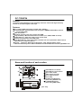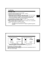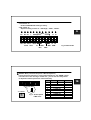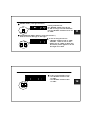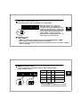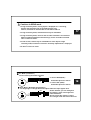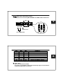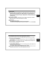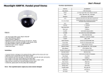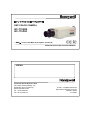
1
DSP COLOR CAMERA
GC-715N24
GC-715P24
* “BMB
BMBTM” is the Trade Mark of Honeywell, CCTV CoE.
READ AND RETAIN THIS OPERATION MANUAL
MEMO
Control Products Business Unit
18F, Kukje Center Building, 191,
Hangangro-2ga, Yongsan-gu,
Seoul 140-702, Korea
Tel : 82-2-799-6109
Fax : 82-2-749-6119
E-mail : [email protected]
http://www.honeywell.co.kr/cctv
Printed in Korea
G-110821
CAUTION
RISK OF ELECTRIC SHOCK
DO NOT OPEN
CAUTION
: TO REDUCE THE RISK OF ELECTRIC SHOCK.
DO NOT REMOVE COVER(OR BACK).
NO USER SERVICEABLE PARTS INSIDE
REFER SERVICING TO QUALIFIED SERVICE PRERSONNEL
Explanation of Graphical Symbols.
This symbol is intended to alert the user to the presence of uninsulated
“dangerous voltage” within the product’s enclosure that may be of
sufficient magnitude to constitute a risk of electric shock to persons.
This symbol is intended to alert the user to the presence of important
operating and maintenance(Servicing) Instructions in the literature
accompanying the appliance.
MEMO
CAUTIONS FOR SAFE OPERATION !
● Changes or modifications not approved
by manufacturer could void the user’s
authority to operate the equipment.
● To prevent fire or shock hazard, do not
expose this camera to rain or moisture.
● To prevent electric shocks and other
hazards, do not use different from the
specified power source.
● Do not install too hot or cold places,
recommended operation temperature
is -10℃ ~ 50℃
● Do not expose lens directly to the sun.
CCD may be damaged.
● Do not place the camera to heavy
shocks or vibrations.
● Do not place or install the camera on
an unstable place, stand, tripod, bracket
or table.
That may cause serious injury to
people or damage to appliance.
1
● Do not attempt to service or repair of
yourself. Please contact all servicing to
qualified service personnel
● In case of installing too close to Monitor,
variation of monitor brightness cause any
hunting of camera in low light mode.
Cautions for safe operation
-------------------------------------
1
About GC-715N/P24
-------------------------------------
3
Name and function of each section
-------------------------------------
4
Installation
-------------------------------------
5
Adjustment and operation
-------------------------------------
8
Specifications
-------------------------------------
23
Accessory
● C mount adapter
● IRIS JACK for AUTO IRIS LENS
2
GC-715N/P24
Outlines
Honeywell’s GC-715N/P24 is a high sensitivity CCD color camera with high sensitivity
function of the field integration technique.
Features
3
☞ 1/3” IT Super HAD CCD ( NTSC: 410,000 / PAL: 470,000 )
☞ Outstanding BLC implementation with Honeywell’s BMB(Black Mask BLC) function.
( 3 levels adjustable )
☞ CS/C lens mount.
☞ Excellent signal-to-noise ratio of more than 50dB.
☞ High Sensitivity : Minimum illumination of 0.001lx ( F1.2, 30IRE, SENS On X 128 )
☞ 2-WAY Auto Iris : Video iris or DC iris lens can be used.
☞ External synchronization with LINE LOCK.
☞ Auto White Balance : Auto white balance realizes true color reproduction within various
light sources. ( 2,800 ºK~8,000 ºK )
☞ Control : Flickerless, Back light compensation , AGC , Manual shutter control,
Maximum Sensitivity select, Auto white Balance/ Indoor/Outdoor/Fluorescent light/ BMB Level
Name and function of each section
②
③
①
④
51 ⑤
⑥
68
148
⑦
⑧
① AUTO IRIS lens connector
② AUTO IRIS lens select switch
③ Sync. select switch
④ Video output connector
⑤ Power input connector
⑥ Power lamp
⑦ DC IRIS level adjustment
(when using DC IRIS lens)
⑧ V- PHASE adjustment
(when using LINE LOCK)
[unit : mm]
4
Installation
Mounting a Lens
1. Remove the protective cap in front of the camera.
2. Confirm the mount ring whether it is for C or CS. * Caution1
3. Attach the lens to the lens mount ring.
4. If the lens has an Auto Iris mechanism, connect the iris cable to the Lens connector
(EE/VSD S/W must be set to VSD on the side of the camera)
A. In the case of having no iris amplifier : Set the slide switch to DC (Down side)
B. In the case of having iris amplifier : Set the slide switch VSD (Upper side)
C. Set the S/W on the side of the camera to DC or VSD, too.
☞ If using lens that has iris amplifier, “LEVEL” and “ALC” volume of lens must be
adjust carefully. It may cause any hunting.
☞ When connecting Auto iris lens, be sure to use the connector to be recommended
by manufacturer. (E4-191, Chuo Musen, Japan)
5
* Caution 1 : This appliance is set to CS mount default.
If you want to use C mount lens, fix a C adapter ring additionally packed
in the box.
When Auto-Iris Lens is used...
VSD LENS PIN CONFIGURATION
3
1
4
①③
②④
2
1. POWER(12V)
3. VIDEO SIGNAL
2. NO CONNECTION
4. GND
Set the select switch to VSD
DC IRIS LENS PIN CONFIGURATION
3
4
1
2
①③
②④
1. CONTROL2. CONTROL+
3. DRIVE+
4. DRIVESet the select switch to DC
* For the best condition, read lens manual carefully .
* After connecting Auto iris-lens you may need to set flange back focus.
Connection of AC power supply
☞ Must be checked the power source from the external power supply before power on.
☞ Recommended power source capacity :
AC 24V, more than 500mA
6
Flange back focus adjustment
1. In case of fixed focus lens
a. Loosen the locking ring and set the focus ring of lens to infinity ( ∞ ) .
b. Tune the mount ring to get a clear picture( distance from camera to object is
more than 23m) and fasten the locking ring.
2. In case of zoom lens
a. Loosen the locking ring and set the lens to the maximum telephoto position.
Then turn the focus ring to focus.
☞ in the case of Auto iris lens, shoot a comparatively dark object or reduce
the ambient light so that the Iris is fully open.
b. Set the lens to its maximum wide angle position, and set the focus.
c. Repeat step a and b, until the difference between focusing position a and b
is smallest.
D. When the best focusing point is found, fasten the locking ring.
7
Adjustment and operations
Configuration
“10” “11”
“6”
LENS
“5”
01
9 0
2
8
76 5 4 3
01
90
2
8
76 43
5
“7”
VSD LL
DC INT
UP
DOWN
“1” “2”
VIDEO
“3”
PUSH LOCK
Fig 1. SIDE view
“4”
LEVEL V-PH
AC24
GND
“8” “9”
Fig 2. REAR view
The function of each part
1. Button “1” & “2”
In line lock mode, zero crossing point can be adjusted by pressing these buttons.
In MWB mode, manual white balance can be adjusted by pressing these buttons.
2. Button “3”
In One push lock mode, white balance can be aligned by pressing this button.
When this button is released, white balance is locked.
8
3. Connector “4”
Used for EEPROM data setting in factory.
4. DIP switch “5”
Shipment setting consists of “AGC High”, “AWC”, “SENS”.
①
②
EE
③
EE DC
④
L
⑤
⑥
BMB
ME VSD VSD H SENS
FL
AUTO AGC
⑦
⑧
⑨
⑩
OFF
⑪
9
⑫
L1 L0
ON
WB3
WB1
BLC
WB2
H1 H0
BMB
Fig 3. Button detail
① “EE/ME” Mode ( Electronic Exposure / Manual Exposure )
If using electronic exposure or a lens with automatic iris, the “EE/ME” switch
has to be set to “EE”. If using a manual lens, you can use the rotary switch
to adjust the shutter speed of the camera manually.
EE
“6” switch
8
7
9 0 1
6 54
2
3
ME
Fig 4. Shutter Speed
in ME mode
Mode 715N24
715P24
0
1/60 sec 1/50 sec
1
1/120 sec 1/100 sec
2
1/250 sec
3
1/500 sec
4
1/1,000 sec
5
1/2,000 sec
6
1/4,000 sec
7
1/5,000 sec
8
1/10,000 sec
9
1/100,000 sec
Remark
default
10
② “EE/VSD” Mode ( Lens type selection )
EE
VSD(Auto)
If using a manual lens,
the “EE/VSD” switch has to be set
to “EE”. If using a lens with automatic
iris, the “EE/VSD” switch has to be set
to “VSD”
11
③ “DC/VSD(AUTO)” Mode ( Auto Iris Lens type selection )
Auto Iris Lens are DC Type or VSD Type.
◆ in case of using DC iris lens.
-. “EE/VSD” switch on side to “VSD”,
“EE/VSD” switch on rear to “DC”.
EE DC
-. Slowly turn “8” LEVEL on Rear until
the monitor picture appears to be not
too bright or too dark.
VSD VSD
EE
DC
Auto
◆ in case of using AUTO iris lens
-. Set “EE/VSD” switch on Side
to “VSD”.
-. Set “EE/VSD” switch on Rear
to “VSD”.
12
④ “AGC” Mode ( Automatic Gain Control )
Select the AGC mode to high ( gain 32dB) or low ( gain 26dB ).
When this switch is to “high”, the
maximum AGC is set to 32 dB, and
sensitivity increases automatically when
illumination becomes dark . In AGC high
mode , the integration time of the memory
can be further decreased than AGC low
mode ( 26dB) , and moving object is
displayed more natural. But the noise of
video signal is further increased .
L
AGC
H
13
⑤ “BMB/SENS” Mode
What is BMB?
-. BMB is the trade mark of Honeywell, that means BLACK MASK BLC. (BMB
BMBTM)
-. It is to improve the weak points of Electronic Iris & BLC.
-. Mask the excessive light by 3 making level and minimize the loss of outlines of Objects
due to strong light.
◆ BMB(Black Mask BLC) Mode
It can be adjustable to 3 levels according to surrounding condition.
( Factory default : 3Level )
BMB
L1
L0
SENS
H1
H0
LEVEL
H1
H0
Remark
OFF
X
X
1
X
O
GRAY
2
O
X
DARK GRAY
3
O
O
BLACK
14
< BMB level adjustment >
As higher BMB level, making level is darker.
and around the masked area become lighter.
☞ It is impossible to use BMB and SENS functions simultaneously !!!
To use BMB or SENS, select “BMB/SENS” switch one of two,
To use neither BMB nor SENS, select “BMB” and level “H1,H0” to OFF.
or select “SENS” and set the Rotary switch “7” to “0”.
◆ SENS( Sensitivity Up mode ) Mode
If the sensitivity ON mode is selected and in low light conditions, the camera
sensitivity is increased by getting picture from the memory.
Maximum sensitivity is selectable out of 9 steps . ( Refer to Fig5 )
BMB
8
7
SENS
Mode
0
1
2
3
4
5
6
7
8
9
9 0 1
6 54
15
2
3
“7” FIELD switch
Setting
OFF
X2
X4
X6
X8
X10
X16
X32
X64
X128
Fields/sec
60
30
15
10
7.5
6
3.8
1.9
0.9
0.5
Remark
16
Default
Fig 5. Maximum sensitivity setting table
☞ In the sensitivity ON mode , sensitivity is automatically controlled within maximum
sensitivity setting value.
! Cautions in SENS mode
1. In high sensitivity mode , moving object is displayed as if it is flowing,
because the integration time of the CCD becomes long.
Further, movement is unnatural due to intermittent read-out.
2. In high sensitivity mode, white blemishes may be remarkable.
17
3. In high sensitivity mode, noises as well as video information are increased.
When an ambient temperature becomes high, noises are further increased.
This is not due to failure.
4. In PAL version, flickers may be remarkable for some objects in high
sensitivity mode, because the electronic sensitivity amplification is employed.
5. It doesn’t work in FL mode.
⑥ “FL” Mode ( Flickerless )
Use for removing the flicker of picture.
OFF
-. In case of NTSC(60Hz) :
Fix Shutter Speed to 1/100 sec
ON
FL
-. In case of PAL (50Hz) :
18
Fix Shutter Speed to 1/120 sec
⑦ “BLC” Mode ( Backlight Compensation )
Too bright light or sunlight behind the object makes the object appear dark .
OFF
-. In BLC ON state, you can distinguish
the objects in front of the bright area
without darkness.
ON
-. Do not use the BLC function if using
the Low-light mode with manual Iris Lens.
BLC
⑧ ⑨ ⑩ “WB” Mode ( White Balance Mode )
WB Mode can be selected by WB1,WB2,WB3, UP,DOWN, PUSH LOCK switch.
OFF
19
OFF
ON
UP DOWN
PUSH LOCK
ON
WB3 WB2 WB1
Use in MWB mode
WB3
OFF
OFF
ON
ON
OFF
ON
OFF
ON
WB2
OFF
ON
ON
OFF
OFF
OFF
ON
ON
WB1
OFF
OFF
OFF
OFF
ON
ON
ON
ON
AWB Mode
ATW Mode
AWC Mode ( Default )
One Push Lock
MWB Mode
Indoor Fixed Mode ( 3200 ºK)
Fluorescent Fixed Mode ( 4200 ºK)
User Fixed Mode ( 4700 ºK)
Outdoor Fixed Mode ( 6300 ºK)
Fig 6. WB Mode Table
◆ “ATW” Mode
Auto Trace White Balance Mode.
This mode is the feedback system that automatically aligns the white balance.
( Operating Range 2,800 ºK~ 8,000 ºK)
20
◆ “AWC” Mode
Auto White Balance Control Mode. This mode performs more faster action than
ATW mode without operating range. AWC operation is also performed in one
push lock mode. while the button “3” on the side view is pressed, AWC action
started and then the button is released, WB operation is locked to fit the present
shooting scene.
21
◆ One Push Lock Mode
In One push lock mode, white balance can be aligned by pressing “3” button.
When this button is released, white balance is locked.
◆ “MWB” Mode
Manual White Balance Mode.
This mode is used for manual adjustment of white balance.
This mode can be adjusted by pressing buttons.(Button“1”, “2” on SIDE VIEW)
6. “9” V-PHASE ( In the line lock mode, Adjustment V-Phase)
When you are using the line lock, the LL/INT switch has to be set to “LL” mode.
a. Line lock zero cross adjustment
; Zero cross point can be adjusted by pressing “1”(UP) and “2”(DOWN) buttons
of the camera
☞ Zero crossing point of shipment state can be initialized after pressing the UP
button (Button“1”) during about 10 seconds .
b. Line lock V-phase adjustment
; If more than two cameras are used in one switching system, phase difference in
AC power line can be occurred.
It is needed to adjust this phase difference for each camera.
☞ If the cameras are connected to different AC lines, you can use the line lock
adjustment potentiometer of the camera (adjustment of V-PH)
22
SPECIFICATIONS
GC-715N24
Imaging device
Effective pixel
Scanning system
Sync system
Scanning frequency
H Resolution
Video out
S/N Ratio
Min. illumination
BLC
White Balance
Elec. Shutter
AGC
Lens Mount
ALC
Power Source
Operating Temp.
Storage Temp.
Weight
Dimensions
1/3” CCD(total 410,000pixels)
768H * 494V(380,000pixels)
525 Lines 2:1 Interlace
Internal/ Line lock
15.734KHz(H), 59.94Hz(V)
480 TV Lines
VBS 1.0Vp-p / BNC
more than 50dB
less than 0.2lx(F1.2, 30IRE, AGC ON)
SENS ON 0.001lx ( X128 fields )
BLC ON/OFF, BMB ON(3Steps)/OFF
AWB(2,800 ºK ~8,000 ºK)
1/60s ~1/100,000s
High / Low
C/CS Mount
EE, VSD, DC
AC24V±10%,500mA
-10℃ ~ +50℃
-20℃ ~ +70℃
436g
68(W) * 51(H) * 148(D)
GC-715P24
1/3” CCD (total 470,000pixels)
752H * 582V(440,000pixels)
625 Lines 2:1 Interlace
Internal/ Line lock
15.625KHz(H), 50.0Hz(V)
480 TV Lines
VBS 1.0Vp-p / BNC
more than 50dB
less than 0.2lx(F1.2, 30IRE, AGC ON)
SENS ON 0.001lx ( X128 fields )
BLC ON/OFF, BMB ON(3Steps)/OFF
AWB(2,800 ºK ~8,000 ºK)
1/50s ~1/100,000s
High / Low
C/CS Mount
EE, VSD, DC
AC24V±10%,500mA
-10℃ ~ +50℃
-20℃ ~ +70℃
436g
68(W) * 51(H) * 148(D)
23