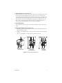
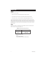
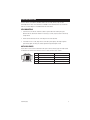
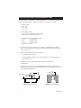
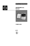
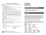
1
INSTALLATION/OPERATION
®
CCC1370H-2, CCC1370H-2X,
and MCC1370H-2
1/3-Inch CCD Camera
C1961M-E (8/03)
CONTENTS
Section
Page
IMPORTANT SAFEGUARDS AND WARNINGS ..................................................................................... 3
REGULATORY NOTICES ............................................................................................................. 4
DESCRIPTION ..................................................................................................................................... 5
MODELS .................................................................................................................................... 5
LOCATION AND FUNCTION OF PARTS ............................................................................................... 6
CONNECTIONS ................................................................................................................................... 8
POWER ...................................................................................................................................... 8
VIDEO ......................................................................................................................................... 8
LENS INSTALLATION .......................................................................................................................... 9
LENS MOUNTING ...................................................................................................................... 9
AUTO IRIS LENSES .................................................................................................................... 9
BACK FOCUS ADJUSTMENT ............................................................................................................. 10
FIXED FOCAL LENGTH LENSES ................................................................................................ 10
MOTORIZED ZOOM LENSES .................................................................................................... 10
CAMERA SYNCHRONIZATION ........................................................................................................... 11
ECLIPSER ADJUSTMENT (NTSC/EIA MODELS ONLY) ...................................................................... 12
SPECIFICATIONS ............................................................................................................................... 13
WARRANTY AND RETURN INFORMATION ......................................................................................... 14
LIST OF ILLUSTRATIONS
Section
1
2
3
Page
Location and Function of Parts ............................................................................................. 7
Gray Level Setting ................................................................................................................ 12
Image on Monitor ................................................................................................................ 12
LIST OF TABLES
Section
A
2
Page
Video Coaxial Cable Requirements ....................................................................................... 8
C1961M-E (8/03)
IMPORTANT SAFEGUARDS AND WARNINGS
Prior to installation and use of this product, the following WARNINGS should be observed.
1. Installation and servicing should be done only by qualified service and installation personnel.
2. Installation shall be done in accordance with all local and national electrical and mechanical
codes utilizing only approved materials.
3. Use only installation methods and materials capable of supporting four times the maximum
specified load.
The product may bear the following marks:
This symbol indicates that dangerous voltage
constituting a risk of electric shock is present
within this unit.
CAUTION:
RISK OF ELECTRIC SHOCK.
DO NOT OPEN.
This symbol indicates that there are important
operating and maintenance instructions in the
literature accompanying this unit.
Please thoroughly familiarize yourself with the information in this manual prior to installation and
operation.
C1961M-E (8/03)
3
REGULATORY NOTICES
This equipment has been tested and found to comply with the limits of a Class B digital device,
pursuant to part 15 of the FCC rules. These limits are designed to provide reasonable protection
against harmful interference in a residential installation. This equipment generates, uses, and can
radiate radio frequency energy and, if not installed and used in accordance with the instructions,
may cause harmful interference to radio communications. However there is no guarantee that the
interference will not occur in a particular installation. If this equipment does cause harmful
interference to radio or television reception, which can be determined by turning the equipment off
and on, the user is encouraged to try and correct the interference by one or more of the following
measures:
• Reorient or relocate the receiving antenna.
• Increase the separation between the equipment and the receiver.
• Connect the equipment into an outlet on a circuit different from that to which the receiver is
connected.
• Consult the dealer or an experienced radio/TV technician for help.
Any changes or modifications not expressly approved by the party responsible for compliance could
void the user’s authority to operate the equipment.
This device complies with part 15 of the FCC Rules. Operation is subject to the following two
conditions: (1) This device many not cause harmful interference, and (2) this device must accept
any interference received, including interference that may cause undesired operation.
This Class B digital apparatus complies with Canadian ICES-003.
Cet appareil numérique de la classe B est conforme à la norme NMB-003 du Canada.
4
C1961M-E (8/03)
DESCRIPTION
The CCC1370H-2, CCC1370H-2X, and MCC1370H-2 digital cameras are high resolution, compact
video cameras that feature a 1/3-inch CCD imager. Each camera’s high resolution and high-density
image sensor ensure a sharp and clear picture over a wide range of conditions.
MODELS
CCC1370H-2
CCC1370H-2X
MCC1370H-2
C1961M-E (8/03)
1/3-inch, high resolution, color CCD camera, 24 VAC, 60 Hz, NTSC
1/3-inch, high resolution, color CCD camera, 24 VAC, 50Hz/12 VDC, PAL
1/3-inch, high resolution, monochrome CCD camera, 24 VAC, 60 Hz, EIA
5
LOCATION AND FUNCTION OF PARTS
Refer to Figure 1.
� Lens Mount
The camera has a standard CS lens mount but can use a C-mount lens when a C/CS-mount
adapter is installed between the lens and camera.
� Back Focus Lock Screw
Loosen to adjust the back focus to match the lens attached to the CS mount. Refer to the
section on Back Focus Adjustment in this manual.
� Camera Mounts
Top or bottom mounting. Maximum thread length is 3/16-inch. Attach the camera mount
adapter to extend thread depth to a standard 1/4-inch.
� Level Adjuster
Controls the video output level when using a DC-controlled auto iris lens.
� Lens Connector
Four-pin auto iris drive connector.
� Video Output Connector
This coaxial connector (BNC type) outputs the video signals.
� Iris Mode Selector Switch
Switch to VIDEO when an auto iris lens is controlled by a video signal. Switch to DC when
using a DC voltage drive lens.
� LL ADJ Switches
Use switches to adjust the vertical phase up or down to eliminate vertical roll when multiple
cameras are connected to a switching device. Each camera’s output is synchronized to the
frequency of the power supply.
� AGC – Automatic Gain Control
Automatically adjusts the image to compensate for changes in light levels. The AGC function
switch can be turned ON/OFF by moving the AGC switch right or left. AGC is factory set to ON.
�� ESC – Electronic Sensitivity Control
This function changes the sensitivity of the camera by varying the electronic shutter speed
according to the amount of incident light. The ESC range is 1:300. To reset the ESC function
switch, move the ON/OFF switch right or left. The ESC is factory set to the ON position.
�� BLC – Backlight Compensation
The backlight compensation function allows fine picture correction to prevent the subject from
being extremely dark due to strong backlight. The BLC function switch can be turned ON/OFF by
moving the BLC switch right or left. The BLC is factory set to the OFF position. Set the AGC
switch to ON when using the BLC function.
6
C1961M-E (8/03)
�� Eclipser Function (NTSC/EIA Models Only)
The eclipser function is used with an auto iris lens. When using a CCD imager with an auto iris
lens in an area with minimal lighting contrasts, the auto iris lens closes, resulting in poor
picture quality. The eclipser function distorts the signal to the auto iris lens, causing the lens to
open wider and create sufficient lighting contrasts to prevent the silhouetting of figures. The
eclipser function switch can be turned ON/OFF by moving the ECLP switch right or left. The
ECLP is factory set to the OFF position. When the auto iris lens used is equipped with a
response selector (AVERAGE/PEAK), always set the selector to AVERAGE.
�� Power Input Terminal
Three-pin terminal strip, push-in type; 24 VAC for NTSC/EIA models; 24 VAC/12 VDC for PAL
model.
�� Eclipser Level Controls (NTSC/EIA Models Only)
a. Threshold – Sets the level for the brightest part of the picture. Anything brighter than this
adjustment will be eclipsed.
b. Eclipse – Sets the brightness of the eclipsed area in the signal that controls the automatic
iris lens.
c. Gray – Sets the brightness of the eclipsed area as viewed on a monitor.
10 9
3
4
5
6
8
10 9
4
5
6
8
LENS
VIDEO
CAMERA MOUNT
ADAPTER
LENS
VIDEO
LEVEL
AGC
ESC
BLC
ECLP
LEVEL
VIDEO
1
2
3
TOP/FRONT VIEW
11 12
13
OFF
AGC
ESC
BLC
LL
ON
VIDEO DC
UP DOWN
OFF ON
24VAC
DC
GRND
24VAC
7 14
BACK VIEW
(NTSC/EIA MODELS)
LL
UP DOWN
DC 12V
THRE ECLP GRAY
11
13
GND
7
BACK VIEW
(PAL MODEL)
Figure 1. Location and Function of Parts
C1961M-E (8/03)
7
CONNECTIONS
POWER
To connect to the power supply:
1. Strip at least .50 inch (13 mm) from the power cord to expose the wires.
2. Insert the three wires into the holes in the terminal strip until they snap into place.
3. Confirm that the cord is connected to terminal securely by lightly tugging on the cord.
If you are wiring more than one camera to the same transformer, connect one side of the transformer to the same terminal on all cameras, and connect the other side of the transformer to the
remaining terminal on all cameras. Failure to connect all of the cameras the same way will cause
the cameras to be out of phase with each other and may produce a vertical roll when switching
between cameras.
VIDEO
Connect a video cable to the SIGNAL OUT connector (BNC) on the rear of the camera. Refer to
Table A for the type of video coaxial cable to use.
Table A. Video Coaxial Cable Requirements
Cable Type*
RG59/U
RG6/U
RG11/U
Maximum Distance
750 ft (229 m)
1,000 ft (305 m)
1,500 ft (457 m)
*Minimum cable requirements:
75 ohms
All-copper center conductor
All-copper braided shield with 95% braid coverage
8
C1961M-E (8/03)
LENS INSTALLATION
The CCC1370H-2, CCC1370H-2X, and MCC1370H-2 can use fixed, manual, or passive (DCcontrolled) auto iris lenses. The camera has a standard CS lens mount but can use a C-mount lens
when a C/CS-mount adapter is installed between lens and camera.
LENS MOUNTING
1. Screw the lens onto the lens mount. Be careful to prevent dust from entering the space
between the lens and the CCD element. If necessary, use clean, compressed air to remove any
foreign matter.
2. Aim the camera and focus the lens to the object or area to be observed.
3. If a manual iris lens is used, adjust the iris for the best picture quality. The largest aperture
gives the best light sensitivity, the smallest aperture the greatest depth of field.
AUTO IRIS LENSES
Passive auto iris lenses are DC-controlled via the 4-pin iris drive connector (type D4-152N) located
on the back of the camera. Pin connections for the iris drive connector are as follows:
2
1
4
3
LENS CONNECTOR
C1961M-E (8/03)
PIN
1
2
3
4
VIDEO SIGNAL CONTROL
+9 VDC (40 mA max.)
+9 VDC (40 mA max.)
AI - Video
GND
DC VOLTAGE CONTROL
Control coil (-)
Control coil (+)
Drive coil (+)
Drive coil (-)
9
BACK FOCUS ADJUSTMENT
Do not release the back focus locking ring unnecessarily. Back focus adjustment has been set at the
factory to the standard CS-mount back focus distance. However, once a lens is mounted it may be
necessary to adjust back focal length to match the lens being used.
FIXED FOCAL LENGTH LENSES
1. Mount the lens firmly to the camera.
2. With the camera operating, position the camera to view an object at least 30 feet (10 m) away.
3. Set the focus ring to infinity ( ).
4. Set the lens iris to its widest usable opening.
5. Adjust the back focus.
a. Use an Allen wrench to loosen the back focus lock screw at the side of the camera.
b. Turn the lens mount to obtain the sharpest image on the monitor.
c. Turn the back focus locking ring clockwise to tighten.
NOTE: Do not over-tighen the back focus lock screw. Over-tightening the back focus lock screw can
damage the threads on the mount of the lens.
MOTORIZED ZOOM LENSES
1. With the camera operating, position the camera to view an object at least 70 feet (25 m) away.
2. Set the lens in the following manner:
a. Set the lens iris to its widest usable opening.
b. Set the lens focus to the FAR position.
c. Adjust lens zoom to WIDE angle.
3. Adjust back focus until the object is in sharpest focus.
a. Use an Allen wrench to loosen the back focus lock screw at the side of the camera.
b. Turn the lens mount to obtain the sharpest image on the monitor.
c. Turn the back focus locking ring clockwise to tighten.
4. Move lens zoom to TELEPHOTO.
5. Zoom out all the way while observing the focus on the monitor (known as “tracking”). If the
image stays in focus throughout the entire zoom range, the back focus is correct. Otherwise,
repeat the process beginning with step 1.
10
C1961M-E (8/03)
CAMERA SYNCHRONIZATION
The power supply of each camera is set to the same synchronized phase at the factory and usually
does not need to be readjusted.
When using more than one camera power supply, a brief vertical roll may occur on the monitor
each time a camera view is switched. To eliminate vertical roll, adjust the phase control by
synchronizing, or line locking, the cameras to one another. Use the LL switches on the back of the
camera to make adjustments.
It may be necessary to have two people in communication when synchronizing the cameras–one
person at the camera and another person at the monitor to observe the vertical roll and the effect
of any adjustments made at the camera.
To synchronize the cameras do the following:
1. Choose a camera to which all of the other cameras will be synchronized.
2. Select a second camera that is out of synchronization with the first camera.
3. Adjust the camera phase by pressing the LL switches up or down.
4. Switch the cameras back and forth, observing the roll between the cameras when they are
switched.
5. Press the LL switches up or down and observe the roll each time an adjustment is made.
6. Repeat this process as many times as necessary for each camera in the system.
C1961M-E (8/03)
11
ECLIPSER ADJUSTMENT (NTSC/EIA MODELS ONLY)
The eclipser function is available only on NTSC and EIA models. It is set at the factory and usually
does not need to be readjusted. However, if fine tuning is necessary, do the following:
1. Set the DIP switches.
a. AGC: OFF
b. ESC: OFF
c. BLC: OFF
2. Set the IRIS MODE selector.
a. Auto iris lens controlled by video signal - VIDEO
b. Auto iris lens controlled by DC voltage - DC
3. Set the variable resistors and Eclipse DIP switch.
a. THRE:
Counterclockwise
b. ECLP:
Mechanical center
c. GRAY:
Mechanical center
d. ECLIPSER DIP: OFF
4. Set the response selector of the auto iris lens (video type) to AVERAGE. While viewing an
object, set the video output level of the camera to 0.75 Vp-p (100 IRE) by adjusting the LEVEL
VR of the auto iris lens.
5. While viewing a brightly lit object (Refer to Figure 2):
a. Set ECLIPSER DIP switch to ON.
b. Adjust THRESHOLD variable resistor by turning it clockwise. Set the video output level to
clip at 0.8~0.85 Vp-p.
c. Set gray level to 0.35 Vp-p by turning the GRAY variable resistor clockwise or
counterclockwise.
6. While viewing an object in front of a bright background (refer to Figure 3), adjust the ECLP
variable resistor by turning it clockwise or counterclockwise until the foreground is clear (sharp)
and the background appears gray.
GRAY
BACKGROUND
GRAY LEVEL
0.8~0.85 Vp-p
0.35 VP-P
v
Figure 2. Gray Level Setting
12
Figure 3. Image on Monitor
C1961M-E (8/03)
SPECIFICATIONS
GENERAL
CCD Sensor:
Picture Elements
CCC1370H-2,
MCC1370H-2:
PHYSICAL
1/3-inch interline
transfer
768H x 494V
(approx. 380K)
CCC1370H-2X: 752H x 582V
(approx. 440K)
Sensing Area:
3/16 x 1/8 - inch
(4.7 mm x 3.5 mm)
Synchronization System
CCC1370H-2,
MCC1370H-2:
AC line lock
CCC1370H-2X: AC line lock/DC
internal
Horizontal Resolution
CCC1370H-2,
CCC1370H-2X: 470 TV lines
MCC1370H-2:
560 TV lines
Iris Control:
Electronic/passive
Minimum Illumination
CCC1370H-2,
CCC1370H-2X: 1.0 lux at f1.2, 75%
highlight reflectance,
at 2500°K
MCC1370H-2:
0.10 lux at f1.2, 75%
highlight reflectance,
at 2500°K
ESC:
300:1
Signal-to-Noise Ratio: >48 dB (AGC off)
Gain Control:
Automatic
Vertical Phase:
+66° +/-90°
Automatic Gain
Control:
Selectable
Backlight
Compensation:
Selectable
Scanning System
CCC1370H-2,
MCC1370H-2:
525 lines,
2:1 interlace
CCC1370H-2X: 625 lines,
2:1 interlace
Signal Processing:
DSP
Auto Iris Lens Type: DC/video control
Video Output:
1Vp-p, 75 ohms
C1961M-E (8/03)
Dimensions:
2.09 (W) x 2.17 (H) x
2.21 (D) inches
(53 x 55 x 56 mm)
Weight (without lens): 0.40 lb (0.20 kg)
ENVIRONMENTAL
Operating
Temperature:
14°F to 122°F
(-10°C to 50°C)
Storage Temperature: -40°F to 140°F
(-40°C to 60°C)
Humidity:
20 to 80%
(non-condensing)
ELECTRICAL
Power Requirements
CCC1370H-2,
MCC1370H-2:
24 VAC, 60 Hz
CCC1370H-2X: 24 VAC, 50 Hz/12 VDC
Power Connector:
3-pin terminal strip,
push-in type
Video Connector:
BNC
Lens Jack:
4-pin connector
(miniature square)
Current Consumption
CCC1370H-2:
240 mA
CCC1370H-2X: 270 mA (24 VAC)/
390 mA (12 VDC)
MCC1370H-2:
220 mA
MECHANICAL
Lens Mount:
Camera Mount:
C/CS mount (Pelco
PCMA40 mount
adapter is needed to
attach C-mount lens)
1/4 x 20, top and
bottom of camera
housing
POWER SUPPLIES
TF2000:
MCS Series
Power Supply:
20 vA power supply,
24 VAC
Power supply for up to
16 cameras, 24 VAC
(Design and product specifications subject to
change without notice.)
13
WARRANTY AND RETURN INFORMATION
WARRANTY
Pelco will repair or replace, without charge, any merchandise proved defective in material or workmanship for a period of one year after the date of
shipment. Exceptions to this warranty are as noted below:
•
•
•
•
•
•
•
•
•
•
Five years on Pelco manufactured cameras (CC3500/CC3600/CC3700 and MC3500/MC3600 Series); two years on all other cameras.
Three years on Genex® Series (multiplexers, server, and keyboard) and 090 Series Camclosure® Camera System.
Two years on 100/150, 200 and 300 Series Camclosure® Camera Systems.
Two years on all standard motorized or fixed focal length lenses.
Two years on Legacy®, CM6700/CM6800/CM8500/CM9500/CM9740/CM9760 Matrix, DF5 and DF8 Series Fixed Dome products.
Two years on Spectra®, Esprit®, and PS20 Scanners, including when used in continuous motion applications.
Two years on Esprit and WW5700 series window wiper (excluding wiper blades).
Eighteen months on DX Series digital video recorders.
One year (except video heads) on video cassette recorders (VCRs). Video heads will be covered for a period of six months.
Six months on all pan and tilts, scanners or preset lenses used in continuous motion applications (that is, preset scan, tour and auto scan modes).
Pelco will warrant all replacement parts and repairs for 90 days from the date of Pelco shipment. All goods requiring warranty repair shall be sent
freight prepaid to Pelco, Clovis, California. Repairs made necessary by reason of misuse, alteration, normal wear, or accident are not covered under
this warranty.
Pelco assumes no risk and shall be subject to no liability for damages or loss resulting from the specific use or application made of the Products.
Pelco’s liability for any claim, whether based on breach of contract, negligence, infringement of any rights of any party or product liability, relating to
the Products shall not exceed the price paid by the Dealer to Pelco for such Products. In no event will Pelco be liable for any special, incidental or
consequential damages (including loss of use, loss of profit and claims of third parties) however caused, whether by the negligence of Pelco or
otherwise.
The above warranty provides the Dealer with specific legal rights. The Dealer may also have additional rights, which are subject to variation from
state to state.
If a warranty repair is required, the Dealer must contact Pelco at (800) 289-9100 or (559) 292-1981 to obtain a Repair Authorization number (RA), and
provide the following information:
1. Model and serial number
2. Date of shipment, P.O. number, Sales Order number, or Pelco invoice number
3. Details of the defect or problem
If there is a dispute regarding the warranty of a product which does not fall under the warranty conditions stated above, please include a written
explanation with the product when returned.
Method of return shipment shall be the same or equal to the method by which the item was received by Pelco.
RETURNS
In order to expedite parts returned to the factory for repair or credit, please call the factory at (800) 289-9100 or (559) 292-1981 to obtain an
authorization number (CA number if returned for credit, and RA number if returned for repair).
All merchandise returned for credit may be subject to a 20% restocking and refurbishing charge.
Goods returned for repair or credit should be clearly identified with the assigned CA or RA number and freight should be prepaid. Ship to the
appropriate address below.
If you are located within the continental U.S., Alaska, Hawaii or
Puerto Rico:
Service Department
Pelco
3500 Pelco Way
Clovis, CA 93612-5699
If you are located outside the continental U.S., Alaska, Hawaii or Puerto Rico:
Intermediate Consignee
Ultimate Consignee
American Overseas Air Freight
Pelco
320 Beach Road
3500 Pelco Way
Burlingame, CA 94010
Clovis, CA 93612-5699
USA
USA
® Pelco, the Pelco logo, Spectra, Genex, Coaxitron, Intercept, Legacy, Esprit, and Camclosure are registered trademarks of Pelco.
™ Spectra III and Spectra III SE are trademarks of Pelco.
© Copyright 2002, Pelco. All rights reserved.
PELCO
CCC1370H-2,
CCC1370H-2X, and
MCC1370H-2
Tested to Comply
with FCC Standards
FOR HOME OR OFFICE USE
14
(CONTROL NO: 1303591011)
C1961M-E (8/03)
REVISION HISTORY
Manual #
C1961M
C1961M-A
C1961M-B
C1961M-C
C1961M-D
C1961M-E
C1961M-E (8/03)
Date
11/99
3/01
3/01
12/01
12/02
8/03
Comments
Original version.
Add information on model CCC1300H-2X.
Revised eclipser adjustment instructions.
Revised for enhanced imager; new model numbers.
Revised information on model CCC1370H-2X.
Corrected specification for minimum illumination.
15
®
World Headquarters
3500 Pelco Way
Clovis, California 93612 USA
USA & Canada
Tel: 800/289-9100
Fax: 800/289-9150
International
Tel: 1-559/292-1981
Fax: 1-559/348-1120
www.pelco.com
ISO9001
Orangeburg, New York Las Vegas, Nevada Eindhoven, The Netherlands Wokingham, United Kingdom Montreal, Canada