1
Click SAVE to save this manual to your computer. Thank you for choosing Honda.
Thank you for purchasing a Honda engine.
This manual coversthe operation and maintenance of G X I 20 and G X I 60
eng~ines and is based
o n G X I60 engine. The QXE type is equipped for both
electric and manual starting; other types are equipped for manual starting
onl$. All information in this publication
is based on the latest product information available a t the time of printing.
Horjda Motor Co., Ltd. reserves the right
t o make changes a t any time
without notice and without incurring any obligation.
No part of this publication may
be reproduced without writtenpermission.
This manual should be considered
a permanent part of the engine
should remain with the engine if it is resold.
and
It is^ illegal in someareas t o operate an engine without a U.S.D.A. qualified
spa~rk arrester; check local
laws and regulations. An optional spark arrester
for this engineis available from any dealership displayingthe Honda Power
Equipment Engines sign.
READ THIS OWNER’S MANUAL CAREFULLY. Pay specialattention
these symbols and any instructions that follow:
,
-Indicates seriousinjuryor
instructions
followed.
are not
to
death WILL result if
-Indicates a strong possibility that serious injury or
death could result if instructions are not followed.
~
1-
-Indicates a possibility that minor injurycan result if
instructions are not followed.
-Indicates that equipment or property
damage
result if instructions are not followed.
can
NOTE:Giveshelpfulinformation.
If alproblem should arise, or if you have any questions about your engine,
consult your Honda engine dealer.
CONTENTS
1 . ENGINE SAFETY .................................................................
2. COMPONENTIDENTIFICATION .............................................
3 . BATTERY CONNECTIONS (for electric starter) .........................
4 . REMOTECONTROLLINKAGE ................................................
5. PRE-OPERATION CHECK ......................................................
1 . ENGINE OIL ....................................................................
2 . REDUCTION GEAR OIL .....................................................
3. AIR CLEANER .................................................................
4 . FUEL .............................................................................
GASOLINE CONTAINING ALCOHOL ...................................
6. STARTING THE ENGINE .......................................................
7. OPERATION .......................................................................
Oil Alert System ..............................................................
8. STOPPING THE ENGINE .......................................................
Highaltitudeoperation .....................................................
9. MAINTENANCE ..................................................................
1 . Oil change ......................................................................
2. Air cleaner service ...........................................................
3. Sediment cup cleaning .....................................................
4 . Spark plug service ...........................................................
5 . Spark arrester maintenance ...............................................
6. Carburetor adjustment .....................................................
10. TRANSPORTING/STORAGE ..................................................
I 1 . TROUBLESHOOTING ...........................................................
12. SPECIFICATIONS ................................................................
13. WIRING DIAGRAM ..............................................................
14. WARRANTY SERVICE ..........................................................
2
3
4
5
6
7
7
8
9
11
12
13
16
17
18
19
20
21
22
25
26
28
29
30
31
33
34
36
I . ENGINE SAFETY
eonda enginesare designed t o give safe and dependable service
if operatedaccording t o instructions. Read andunderstandthisOwner’s
Manual before operating the engine. Failure to so
do could result in personal injury or equipment damage.
To prevent fire hazards and t o provide adequate ventilation, keep the
engine at least 1 meter (3feet) away from buildings and other equipment during operation. Do not place flammable objects close to the
engine.
Children and pets must be kept away from the
area of operation due t o
a possibility of burns from hot engine components or injury from any
equipment the engine may be used to operate.
Know how to stop the engine quickly, and understand the operation of
all controls. Never permit anyonet o operate the engine without proper
instructions.
Gasoline
is
extremely
flammable
and
is
explosive
under
certain
conditions.
Refuel in a well-ventilated area with the engine stopped. Do not smoke
or allow flames or sparks
in the refueling areaor where gasoline is
stored.
Do not overfill the fuel tank. Afterrefueling, make sure the tank cap is
closed properly and securely.
Be careful not to spill fuel when refueling. Fuel vapor or spilled fuel may
i,gnite. If any fuel isspilled, make sure thearea is dry before starting the
engine.
Never run the enginein an enclosed or confinedarea. Exhaust contains
poisonouscarbonmonoxide
gas; exposuremaycause
loss ofconsciousness and may lead t o death.
The muffler becomes very hot during operation and remains hot for a
while after stopping the engine.
Be careful not to touch the muffler
while it is hot. To avoid severe burns or fire
hazards, let theengine cool
before transporting it or storing it indoors.
3
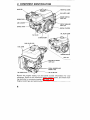
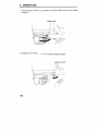
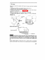
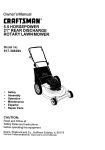
2. COMPONENT IDENTIFICATION
MUFFLER
THROTTLE LEVER
OIL ALERT LAMP
ENGINE SWITCH
(QXE type)
SPARK PLUG
AIR CLEANER
CIRCUIT BREAKER
(QXE type)
CHOKE LEVER
RECOIL STARTER
FUEL VALVE
OIL ALERT LAMP
I
STARTER GRIP
FUEL FILLER CAP
ENGINE SWITCH
QXS type
,
ELECTRIC STARTER
(QXE type)
SERIAL NUMBER AND
ENGINE TYPE
OIL
OILDRAIN PLUG
FILLER CAP
Record the engine model, type and serial number information for your
reference. Refer to this information when orderingparts, and when making technical or warranty inquiries (see page 36).
Engine model type and serial number:
4
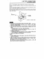
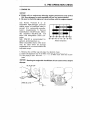
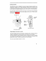
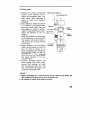
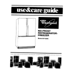
3. B A T T E R Y C O N N E C T I O N S
(for electric starter)
l
Use a 12 volt battery with an ampere-hour rating of at least 18 AH.
Connect the battery positive (+) cable t o t h e starter solenoid terminal, as
shown.
Connect the battery negative (-1 cable t o an engine mounting bolt, frame
bolt, or other good engine ground connection.
Check the battery cable connections
t o be sure the cablesare secured and
free of corrosion. Remove any corrosion and coat the terminals and cable
ends with grease.
,STARTER
SOLENOID
'
POSITIVE
(+I BATTERY CABLE
t h e battery gives off explosivegases; keep sparks, flames and cigarettes away. Provide adequate ventilation when charging or using batkeries in an enclosed space.
The battery contains sulfuric acid (electrolyte). Contact
with skin or
pyes may cause severe burns. Wear protective clothing and a face
Fhield.
!If electrolyte gets on your skin, flush with water.
~If electrolyte gets in your eyes, flush with water for at least
15
minutes and call a physician immediately.
Electrolyte is poisonous.
~If swallowed, drink large quantities of water or milk and follow with
I milk of magnesia or vegetable oil and call a physician.
!KEEP OUT OF REACH OF CHILDREN.
~
0
I NOTICE I
0
0
use only distilled water in the battery. Tap water
vice life of the battery.
will shorten the ser-
filling the battery above the
UPPER LEVEL line may cause the elec~trolyte to overflow, resulting in corrosion t o engine or nearby parts.
~lmmediately wash off any spilled electrolyte.
be careful not to connect the battery in reverse polarity, as this will
;short circuit the battery charging system.
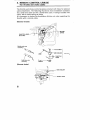
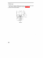
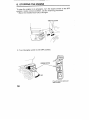
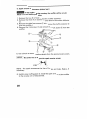
4.REMOTE CONTROL LINKAGE
(for throttle and choke cables)
The throttle and choke control leversare provided with holes for optional
cable attachment. The following illustrations show installation examples
for a solid wire cable and for a braided wire cable. If using a braided wire
cable, add a return spring as shown.
It is necessary t o loosen the throttle lever frictionnut when operating the
throttle with a remote cable.
[Remote throttle]
THROTTLE LEVER
PIVOT NUT
Y
Flexible wire core
4 mm SCREW
WIRE
WIRE HOLDER
’ OPTIONAL
THROTTLE
LEVER
mounting
[Remote choke1
WIRE HOLDER
. CHOKE LEVER
6
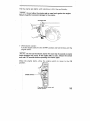
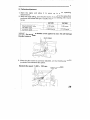
5 . PRE-OPERATION CHECK
I. ENGINE OIL
I NOTICE 1
Engineoilis a major factor affecting engineperformanceandservice
life. Non-detergent oils and vegetable oils are not recommended.
Be sure to check the engine on a level surface with the engine stopped.
i
Use
Honda
4-stroke
an
oil
or
equivalenthigh-detergent,premium
quality motor oil certified to meetor
exceed U.S. automobile
manufacturer's
requirements
for
Service
Cla'ssification SG.SF/CC.CD. Motor
oils
classified
SG.SF/CC.CD.
will
con- thedesignation
on
thisshow
tairjer.
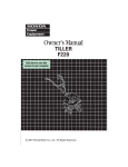
SAE IOW-30 recommended
is
for
general, all-temperature
use.
Other viscosities shown in the chart
may
be
used
when
the
average
temperature in your area is within the
indicated range.
I
2OW-40.2OW-56
I
1
I
I
-20
0
20
I
40
60
-lo
I
100°F
I
1
-30 -20
80
lo
2o
30 40"c
temperature
Ambient
1. Remove the oil filler cap and wipe the dipstick clean.
2. l~nsert the dipstick into the oil filler neck
but do not screw it in.
3. Iif the level is low, fill to the top of the oil filler neck with the recommended oil.
Running the engine with insufficient oil can cause serious engine
damage.
OIL FILLER CAP
7
2. REDUCTION GEAR OIL (Only on equipped model)
<I /2reduction with
automatic centrifugal clutch>
1. Remove the oil filler cap and wipe the dipstick clean.
2. Insert the dipstick into the filler neck but do not screw it in.
3. If the level is low, fill to the upper level mark with the same oil recommended for the engine (see engine oil recommendations on page 7).
Oil capacity: 500 cc (17 US
02,
14 ImD 0 2 )
p
=
y
DIPSTICK/FILLER CAP
UPPER LEVEL
DRAIN BOLT
<1/ 6 reduction>
1. Remove the oil level bolt.
2. Check the oil level; it should reach the edge of the oil level bolt hole. If
the oil level is low, remove the filler bolt, and add
oil until it starts to
flow out the oil level bolt hole. Use the same oil recommended for the
engine (see engine oil recommendations on page 7).
3. Install the oil level bolt and filler bolt. Tighten them securely.
Oil capacity: 150 cc (5.1US
02,
4.2 Imp 0 2 )
FILLER BOLT
OIL LEVEL BOLT
3. AIR CLEANER
Never run the engine without the air cleaner. Rapid engine wear
will result from contaminants, such as dust and dirt, being drawn through
the: carburetor and into the engine.
'I
..'
<Dual element type>
Check the air cleaner elements t o be
sur~ethey are cleanand in goodconditi~on. Clean or replace the elements
if necessary (p.22).
ELEMENTS
<Cbclone type>
1 . Check the air cleaner element t o
be sure theyare clean and in good
condition.
Flean orreplace theelements if
necessary (p.23).
2. Checkthecyclonehousing,and
clean it if it is cloggedorexcessively dirty (p.23).
CYCLONE HOUSING
ELEMENTS
<Oil bath type>
1 . Check the air cleaner element t o be sure it is clean and in good condition. Clean or replace the element if necessary (page 24).
2. Check oil level and condition.
OIL LEVEL
. 10
4. FUEL
that has a pumpoctane
Yourengineisdesigned
t o useanygasoline
) of 86 or
higher,
or
t h a t has a research
ocnumber (
tanle number of 91 or higher. Gasoline pumps a t service station normally
display the pump octane number.
We recommend that you use unleaded fuel because
it produces fewer
engine and spark plug deposits and extends
the life of exhaust system
components.
‘2
NeGer use stale or contaminated gasoline or an oil/gasoline mixture. Avoid
getring dirt, dust or water in the fuel tank.Use of a lower octane gasoline
can cause persistent “pinging” or heavy ”spark knock” (a metallic rapping:noise) which, if severe, can lead to engine damage.
If ”spark knock” or “pinging” occurs at a steady engine speed
under normal load, change brands of gasoline. If spark knock or pinging
persists, consult your authorized Honda
dealer. Failure to do so is considered misuse, and damage caused by misuse is not covered by Honda’s
Limited Warranty.
OcCasionally you may experience light spark knock while operating under
heavy loads. This is no cause for concern, it simply means your engine is
operating efficiently.
Gasoline
is
extremely
flammable
and
is
explosive
under
certain
conditions.
Refuel in a well-ventilated area with the engine stopped. Do not smoke
or allow flames or sparks in the area where the engine is refueled or
where gasoline is stored.
Do not overfill the fuel tank (there should be no fuelin the filler neck).
After refueling, make sure the tank cap is closed properly and securely.
Be careful not to spill fuel when refueling. Spilled fuel
or fuel vapor may
ibnite. If any fuel is spilled, make sure the
area is dry before starting the
engine.
Avoid repeated or prolonged contact with skin or breathing of vapor.
KEEP OUT OF REACH OF CHILDREN.
Fuel tank capacity: GX120 : 2.5 L‘ (0.66 US Gal, 0.55 Imp Gal.)
GX160 : 3.6 L‘ (0.95 US Gal, 0.79 Imp Gal.)
11
GASOLINES CONTAINING ALCOHOL
If youdecide t o use a gasoline containing alcohol (gasohol),be sure its octane rating is a t least as high as that recommended by Honda. There are
t w o types of "gasohol": one containing ethanol, and the other containing
methanol. Do not use gasohol that contains more than 10% ethanol. Do
not use gasoline containing methanol (methyl or wood alcohol) that does
not also contain cosolvents and corrosion inhibitors for methanol. Never
use gasoline containing more than5% methanol, even if it has cosolvents
and corrosion inhibitors.
NOTE:
Fuel system damage or engine performance problems resultingfrom the
use of fuels that contain alcohol is not covered under the warranty.
Hondacannot endorse the use of fuelscontainingmethanolsince
evidence of their suitability is as yet incomplete.
Before buying fuel from an unfamiliar station, try to find out if thefuel
contains alcohol, if it does, confirm t h e type and percentage of alcohol
used. If you notice any undesirable operating symptoms while using a
gasoline that contains alcohol, or one that you think contains alcohol,
switch to a gasoline that you know does not contain alcohol.
12
6. STARTING THE ENGINE
1. Turn the fuel valve to the ON position.
FUEL VALVE
2. Move the choke lever to theCLOSE position.
NOTE: The choke may not be needed
temperature is high.
if the engine is warm
or the air
CHOKE LEVER
13
~~
~
3. Move the throttle lever slightly to the left.
THROTTLE LEVER
4. Start the engine.
0
With recoil starter:
Turn the engine switch to the ON position.
ENGINE SWITCH
(Type with electric starter and
oil alert system)
14
Pull the starter grip lightly until resistance is felt, then pull briskly.
Do not allow the starter grip to snap back against the
engine.
Return it gently to prevent damage to the starter.
STARTER GRIP
0
With electric starter:
Turn the engine switch to the
START position and holdit there until the
engine starts.
Do not use the electric starter for more than
5 seconds or starter
motor damage may occur. If the engine falls t o start, release the switch
and wait 10 seconds before operating the starter again.
When the
position.
~
engine starts, allow the engine switch to return to the
ON
ENGINE SWITCH
(Type with electric starter and
oil alert system)
15
7.OPERATION
1. As the engine warms up, gradually move the choke lever to the OPEN
position.
CHOKE LEVER
2. Position the throttle lever for the desired engine speed.
THROTTLE LEVER
16
0il.Alert System
The Oil Alert system is designed to prevent engine damage caused
by an
insufficient amount of oil
in thecrankcase.Beforetheoillevel
in the
crankcase can fall below a safe limit, the
Oil Alert system will automatically shut down the engine (the engine switch will remain
in the ON position).
If the Oil Alert system shuts down the
engine, the Oil Alert lamp will flash
when you operate the starter, and the engine will not run. If this occurs,
add engine oil (page 7).
OIL ALERT LAMP
OIL ALERT
,/LAMP
ENGINE
SWITCH
(with electric starter)
(without electric starter)
Circuit Breaker (for electric starter)
The circuit breaker protects the battery charging circuit. A short circuitor
a battery connected in reverse polarity will trip the circuit breaker.
The green indicator inside the circuit breaker will pop out to show that the
circuit breaker has switched off. If this occurs, determine the cause of the
problem and correct it before resetting the circuit breaker.
Push the circuit breaker button to reset.
8. STOPPING THE ENGINE
To stop the engine in an emergency, turn the engine switch to the OFF
position. Under normal conditions, use the following procedure:
1 . Move the throttle lever fully to the right.
THROTTLE LEVER
2. Turn the engine switch to the OFF position.
(Type with electric starter and
oil alert system)
18
3.1Turn the fuel valve t o t h e OFF position.
FUEL VALVE
\
*High altitude operation
A t high altitude, the standard carburetor air-fuel mixture
will be excessively rich. Performance will decrease, and fuel consumption will increase.
a smaller diameter
High altitude performance can be improved by installing
main fuel jet
in the carburetor and readjusting the pilot screw. If you
always operate the engine at altitudes higher than 6,000 feet above sea
level, have your authorized Honda Engine
dealer perform these carburetor
modifications.
Even with suitable carburetor jetting, engine horse.power
will decrease approximately 3.5% for each 1,000 foot increase in altitude. The effect of
altitude on horsepowerwill be greater than thisif no carburetor modification is made.
Operation of the engine at an altitude lower than thecarburetor
is jetted for may result in reduced performance, overheating, and serious
engine damage caused by an excessively lean aidfuel mixture.
19
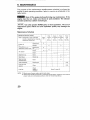
9. MAINTENANCE
The purpose of the maintenance and adjustment schedule is t o keep the
engine in good operating condition. Inspect or service as scheduled in the
table below.
Shut off theengine before performing any maintenance. If the
engine must be run, make sure the area is well ventilated. The exhaust
contains poisonous carbon monoxide gas.
Use only genuine HONDA parts or their equivalent. The use of
replacement parts which are not of equivalent quality may damage the
engine.
Maintenance Schedule
REGULAR SERVICE PERIOD
ITEM
Performed
at every
indicated
month or operating
hour
interval,
use
whichever comes first.
Engine oil
Reduction gear
Check
leveloil
(applicablemodelsonly)
Air cleaner
Check level
Every
year
or
300 Hrs.
Each
0
~
Change
0
0
0
Change
0
0
Check
Clean
O(1)
0
Clean
0
0
Clean
O(2)
I
line
Fuel tank and
strainer
Clean
Fuel
Check
(Replace if
necessary)
O(2)
I
I
I
Every 2 years ( 2 )
NOTE: (1) Service more frequently when used in dusty areas.
(2) These items should be serviced by an authorized Honda dealer, unless the owner has the
proper tools and is mechanically proficient. See the Honda Shop Manual.
20
oil change
1.
Drain the oil while the engine
draning.
is still warm to assure rapid and complete
1 . Remove the oil filler cap and drain plug t o drain the oil.
2. Install the drain plug and tighten it securely.
3. Refill with the recommended oil (see page 7) and check the oil level.
4. Install the oil filler cap.
EN'GINE OIL CAPACITY: 0.6
(0.63USqt, 0.53 Imp qt)
l l 2 REDUCTION GEAR OIL CAPACITY: 500 cc (17 US 02, 14 Imp 02)
[E~GINEOIL]
LEVEL DRAIN PLUG
[REDUCTION GEAR OIL]
,
DRAIN BOLT
Used motor oil may cause skin cancer ifreDeatedlv left in conta4t with the skin for prolonged periods. Although this is uniikely unless
you handle used oil on a daily
basis, it is still advisableto thoroughly wash
your hands with soap and water as soon as possible after handling used
oil.!
NqTE: Please dispose of used motor oil in a manner that is compatible
it on the ground.
wiTh the environment. Do not throwit in the trash or pour
i
21
2. Air cleaner service
A dirty air cleaner will restrict air f l o w t o the carburetor. To prevent carburetor malfunction, service the
air cleaner regularly. Service more frequently when operating the engine in extremely dusty areas.
Never use gasoline or low flash point solvents for cleaning the
air cleaner element. A fire or explosion could result.
Never run the engine without the air cleaner. Rapid engine wear
will result.
<Dual element type>
1 . Remove the wing nut and the air
cleanercover.Removethe
elementsandseparatethem.
Carefully
check
both
elements
for
holes or tears
and
replace
if
damaged.
2. Foam element: Wash the element
in asolutionofhousehold
detergentandwarmwater,then
rinse
thoroughly,
wash
or
in
nonflammableor high flashpoint
solvent. Allow the element to dry
thoroughly.
Soak theelement in cleanengine
oil and squeeze out the excessoil.
The engine will smoke during initial start-up if too much oil is left
in the foam.
3. Paper element:Taptheelement
lightly several times on a hard surfacetoremoveexcessdirt,
or
blow compressed air through the
filter from theinside out. Nevert r y
t o brush the dirt off; brushing will
force dirt into the fibers. Replace
the paper element
if
it is
excessively dirty.
22
AIR CLEANER
PAPER
ELEME
ELEMENT
<C:yclone type>
1 . Remove the wing nut and the air
cleanercover.Removethe
elementsandseparatethem.
Carefully check
both
elements
for
holes
or
tears
and
replace
if
damaged.
2. Foam element: Wash the element
in a solution of household detergent and warm water, then rinse
thoroughly,orwash
in nonflammable or high flash point solvent.
Allow theelement t o drythoroughly.
Soak the element in clean engine
oil and squeeze out theexcess oil.
The engine will smoke during
initial start-up if too much oil is left
in the foam.
3. Paper element: Tap the element
lightly several times ona hard surfacetoremoveexcessdirt,
or
blow compressed air through the
filter from theinside out. Nevert r y
{ o brush the dirt off; brushing will
force dirt into the fibers. Replace
$he
paper
element
if
it is
exCessively dirty.
4. Cyclone
Housing:
Remove
the
(hreespecialpanheadscrews,
iemovethe
housing,andwash
ihe components with water. Dry
the components thoroughly, and
carefully reassemble them.
0
SPECIAL PAN SCREW (31
. .
\
PRE-CLEANER CAP
HOUSING
When reinstalling the cyclone housing, be sure that the air intake tab
fits properly into the groove in the pre-cleaner cap.
Be careful to install the air guide as shown.
23
<Oil bath type>
1. Unscrew the wing nut, remove the air cleaner cover and remove the
element.
2. Washtheelement
in a solutionofhouseholddetergentandwarm
water, then rinse thoroughly,
or wash in nonflammable or high flash
point solvent. Allow the element to dry thoroughly.
3. Soak the element in clean engine oil and squeeze out the excess oil.
The engine will smoke during initial start-up if too much oil is in
leftthe
element.
4. Empty the oil from theair cleaner case and wash out any accumulated
dirt with nonflammable or high flash point solvent. Dry the case.
5. Fill theair cleaner caset o t h elevel markwith the same oil that is recommended for the engine (see engine oil recommendations on page 7).
6. Reinstall the element and the cover.
OIL CAPACITY: 60 cc (2.0 US 02, I.69 Imp
AIR CLEANER COVER
ELEMENT
24
02)
3.~
Sediment cup cleaning
,
Gasoline is extremely flammable and is explosive undercertain
conditions. Do not smoke or allow flames or sparks in the area.
OFF. Remove the sediment cup
and O-ring andwash
Turn the fuel valve to
them in nonflammable or high flash point solvent. Dry them thoroughly
and reinstall securely. Turn the fuel valve ON and check for leaks.
If any fuel is spilled, make sure the area is dry before testing
the spark plug or starting the engine. Fuel vapor or spilled fuel may ignite.
O-RING
SEDIMENT CUP
4. Spark plug service
Recommended spark plug: BPRGES (NGK)
W20EPR-U(ND)
Never use a spark plug of incorrect heat range.
To ensure proper engine operation, the spark plug must be properly gapped and free of deposits.
1. Remove the spark plug cap and use a spark plug wrench to remove the
Plug.
If the engine has been running, the muffler will be very hot. Be
careful not to touch the muffler.
SPARK PLUG WRENCH
2. Visually inspect the spark plug. Discard it if the insulator is cracked or
chipped. Clean the spark plug with a wire brush if it is to be reused.
3. Measure the plug gap with a feeler gauge. The gap should
be 0.7-0.8
mm (0.028-0.031 in).Correct as necessary by bending the side
electrode.
0.7-0.8 mm
(0.028-0.031 in)
26
4. ,Check that the spark plug washer is in good condition and thread the
!spark plug in by hand t o prevent cross-threading.
5. ;After the spark plug is seated, tighten
with a spark plug wrench to com;press the washer.
NOTE: When installing a n e w spark plug, tighten 1/2 turn after the spark
plug seats t o compress the washer. When reinstalling a used spark plug,
tighten 1/8- 1/4 turn after the spark plug seats to compress the washer.
The sparkplug
mustbe
securely tightened. An improperly
tightened spark plug can become very hot and may damage the engine.
27
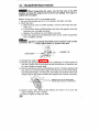
5. Spark arrester maintenance (optional part)
If the engine has been running, the muffler will be very hot.
Allow it to cool before proceeding.
1. Remove the t w o 8 mm nuts @ and the muffler assembly.
2. Remove the three 4 mm screws @ and remove the exhaust deflector
0.
3. Remove the eight5 mm screws @ and remove the muffler protector
@
from the muffler @.
4. Remove the 4 mm screw @ and remove the spark arrester@ from the
muffler.
5. Use a brush t o remove carbon deposits from the spark arrester screen.
Be careful not to damage the spark arrester screen.
SCREEN
NOTE: The spark arrester must be free of breaks and holes.
necessary.
Replace, if
6. Install a new muffler gasket8.
Install the spark arrester and the muffler
in the reverse order of disassembly.
28
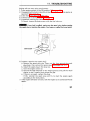
6. 'Carburetor adjustment
1. startthe
engineandallow
it towarmuptonormaloperating
temperature.
2. With the engine idling, turn the pilot screwin or out to the setting that
produces the highest idle rpm. Usually the correct settingwill be found
t o be:
I
~
~
Dualelementtype
Oil bathtype
Cyclonetype
GX120
G X I 60
2.0 turns
3.0 turns
2 318 turns
2 1/8 turns
~
Do not tighten the pilot screw against its seat; this will damage
the' pilot screw or seat.
3. /jfter the pilot screw is correctly adjusted, turn the throttle stop screw
t,o obtain the standard idle speed.
Standard idle speed: 1,400
&
100 rpm.
THROTTLE STOP SCREW
,
29
10. TRANSPORTING/STORAGE
When transporting the engine, turn the fuel valve to the OFF
position and keep the engine level to prevent fuel spillage. Fuel vapor or
spilled fuel may ignite.
Before storing the unit for an extended period;
1. Be sure the storage area is free of excessive humidity and dust.
2. Drain the fuel...
a. With the fuel valve in the OFF position, remove and empty the sediment cup.
ON position and drainthe gasoline from the
b. Turn the fuel valve to the
fuel tank into a suitable container.
C. Replace the sediment cup and tighten securely.
d. Drain the carburetor by loosening the drain screw. Drain the gasoline
into a suitable container.
Gasoline is extremely flammable and is explosive undercertain
conditions. Do not smoke or allow flames or sparks in the area.
SEDIMENT CUP
DRAIN SCREW
3. Change the eng
4. Remove the spark plug and pour about
a tablespoon of clean engine oil
into the cylinder. Crank the engine several revolutionsto distribute the
oil, then reinstall the spark plug.
5. Pull the starter rope slowlyuntil resistance is felt. Continue pulling until
the notch on the starter pulley
aligns with the hole on the recoil starter
(see illustration below). At this
point, the intake and exhaust valves
are
closed, and
this
.
rotect
the engine from
internal
corrosion.
Align the arrow on the starter pulley
with the hole at the top of recoil starter.
6. Electric starter type: Remove the battery and store
place. Recharge it once a month.
7. Cover the engine t o keep out dust.
30
it in acool,
dry
1 I . TROUBLESHOOTING
Engine will not start using recoil starter:
1 . is the engine switch in the ON position? (See page 14.)
2. ,If equipped with oil alert, does the oil alert lamp flash when the starter is
:operated? (See page 7.)
3. the fuel valve ON? (See page 13.)
4. is there fuel in the fuel tank? (See page 4.)
5. Is gasoline reaching the carburetor?
To check, loosen the drain screw with the fuel valve on.
is
If any fuel is spilled, make sure the area is dry before testing
the spark plug or starting the engine. Fuel vapor or spilled fuel may ignite.
DRAIN SCREW
6. 1:s there a spark at the spark plug?
a. Remove the spark plug cap. Clean any dirt from around the spark
I plug base, then remove the spark plug. (See pages 26, 27.)
tj. Install the spark plug in the plug cap.
c . Turn the engine switch on.
d . Ground the side electrode to any engine ground, and pull the recoil
starter to see if sparks jump across the gap.
e . If there is no spark, replace the plug.
If OK, reinstallthesparkplugandtrytostartthe
engineagain
j according to the instructions.
7. If the engine still does not start, take the engine
t o an authorized Honda
dealer.
~
31
Engine will not start using electric starter:
1. Are the battery cables securely connected and free of corrosion?
2. Is the battery fully charged?
NOTE: Ifthe
breaker.
enginedoesnotcharge
the battery,checkthecircuit
3. If the starter motor operates but the engine
will not start, follow the
troubleshooting procedures described under "engine will not start using the recoil starter". (See page 31 .)
32
12. SPECIFICATIONS
GX120
I
Dl,MENSlONS AND
W,EIGHT
Description code
GXI 20
GCOI
3 0 0 x 345 x 320 mrn
(1 1.8x 13.6 x 12.6 in)
Length x Width x Height
Dry weight 12.0 ka (26.5
Ib)
Engine type
4-stroke, overhead valve, single cylinder
1 1 8 cc (7.3 cu in)
160 x 42 mm (2.4 inx 1.7 in)l
Displacement
[Bore x Stroke]
Max. output
4.0 HP/3,600 rpm
0.75 kg (5.4 ft-lb)l2,500 rpm Max. torque
Fuel consumption
230 glPS h
Forced air Cooling
system
Transistorized magneto Igr$tion system
P I 0 shaft rotation
Counterclockwise
GX160
DIMENSIONS AND
WEIGHT
GX160
GC02
Description code
305 x 3 6 5 x 3 3 5 rnm
(12.0 x 14.4 x 13.2 in)
Length x Width x Height
Dry weight
14.0 kg (30.9 Ib)
4-stroke, overhead valve, single cylinder
Engine type
163 cc 19.9 cu in)
[68 x 45 rnm (2.7 in x 1.8 in)]
Displacement
[Bore x Stroke]
5.5 HP/3,600 rpm Max. output
I
Max. torque
Fuel consumption
Cobling system
I
ft-lb)/2.500
(8.0
1 .Ika
rDm
230 SIPS h
Forced air
Transistorized magneto Ignition system
PTO shaft rotation
Counterclockwise
NOTE: Specifications may vary accordingto the types, and
are subject t o
change without notice.
33
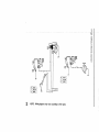
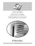
-
OFF
IGNITION
COIL
1
W
BI
BI
I
I
BLACK
WHITE
1
R
Gr
I
I
RED
GRAY
1
MAIN FUSE
CIRCUIT
DIODE
(5A BLADEPROTECTOR
TYPE)
I
NOTE: Wiring diagrams may vary according to the types.
SPARK
PLUG
-
I
BI
BUR
CONTROL BOX BLOCK
COMBINATION
SWITCH
T
IGNmlON
SWITCH
-Y
G-
0
NOTE: Wiring diagrams may varyaccording tothe types.
14. WARRANTY SERVICE
Owner Satisfaction
Your satisfaction and goodwill are important to yourdealer and t o us. All
Honda warranty details are explained in the Distributor’s Limited Warranty. Warranty service is available at any dealership displaying the Honda
Power Equipment Engines sign. To locate dealers in your area, look in the
yellow pages of your telephone directory under GasolineEngines, Garden
& Lawn Equipment & Supplies, Lawn Mowers, etc.
1 Engines
Normally,anyproblemconcerningtheengine
will behandled bv the
dealer‘s-service~department.If you have a warranty problem that has not
beenhandled t o yoursatisfaction, w e suggest you take the following
action:
Discuss vour Droblem with a member of dealership management. Often
complaints can be quickly resolved at that level. If the problem has
already been reviewedwith the Service Manager, contact the owner of
the dealership or the General Manager.
0
If your problem still has not been resolved
t o your satisfaction, contact:
American Honda Motor Co., Inc.
P.O. Box 100021
Duluth, Georgia 30136-9421
Telephone: (404) 497-6400
We will need the following informationin order t o assist you:
- Your name, address, and telephone number
- Engine model and serial number
- Date of purchase
- Dealer name and address
- Product or equipment in which the engine is installed.
- Nature of the problem
After reviewing all the facts involved, you will be advised of what action
can be taken.Please bear in mind that your problemwill likely be resolved
a t t h e dealership, using the dealer’s facilities, equipment, and personnel,
so it is very important that your initial contactbe with the dealer.
Yourpurchaseof
a Hondaengineisgreatlyappreciated
by both your
dealer and American Honda Motor
Co., Inc. W e w a n t tassist
o
you in every
w a y possible t o assure your complete satisfaction with your purchase.
36