1
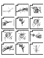
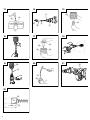
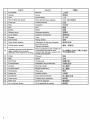
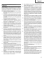
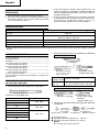
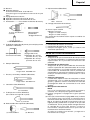
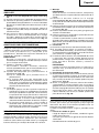
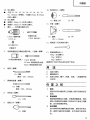
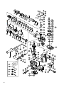
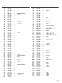
1
2
3
5
2
1
4
3
6
4
7
5
6
0
9
7
9
0
0
8
9
8
8
6
9
10
11
12
C
A
D
B
1
8
E
13
14
15
J
5
C
F
H
K
4
I
6
G
16
17
18
M
J
19
J
20
K
J
P
73
7 mm
17 mm
2
Q
N
21
K
22
L
O
English
GENERAL OPERATIONAL PRECAUTIONS
WARNING! When using electric tools, basic safety
precautions should always be followed to reduce the risk
of fire, electric shock and personal injury, including the
following.
Read all these instructions before operating this product
and save these instructions.
For safe operations:
1. Keep work area clean. Cluttered areas and benches
invite injuries.
2. Consider work area environment. Do not expose
power tools to rain. Do not use power tools in damp
or wet locations. Keep work area well lit.
Do not use power tools where there is risk to cause
fire or explosion.
3. Guard against electric shock. Avoid body contact
with earthed or grounded surfaces. (e.g. pipes,
radiators, ranges, refrigerators).
4. Keep children away. Do not let visitors touch the
tool or extension cord. All visitors should be kept
away from work area.
5. Store idle tools. When not in use, tools should be
stored in a dry, high or locked up place, out of reach
of children.
6. Do not force the tool. It will do the job better and
safer at the rate for which it was intended.
7. Use the right tool. Do not force small tools or
attachments to do the job of a heavy duty tool. Do
not use tools for purposes not intended; for example,
do not use circular saw to cut tree limbs or logs.
8. Dress properly. Do not wear loose clothing or
jewelry, they can be caught in moving parts. Rubber
gloves and non-skid footwear are recommended
when working outdoors. Wear protecting hair
covering to contain long hair.
9. Use eye protection. Also use face or dust mask if
the cutting operation is dusty.
10. Connect dust extraction equipment.
If devices are provided for the connection of dust
extraction and collection facilities ensure these are
connected and properly used.
11. Do not abuse the cord. Never carry the tool by the
cord or yank it to disconnect it from the receptacle.
Keep the cord away from heat, oil and sharp edges.
12. Secure work. Use clamps or a vise to hold the work.
It is safer than using your hand and it frees both
hands to operate tool.
13. Do not overreach. Keep proper footing and balance
at all times.
14. Maintain tools with care. Keep cutting tools sharp
and clean for better and safer performance. Follow
instructions for lubrication and changing
accessories. Inspect tool cords periodically and if
damaged, have it repaired by authorized service
center. Inspect extension cords periodically and
replace, if damaged. Keep handles dry, clean, and
free from oil and grease.
15. Disconnect tools. When not in use, before servicing,
and when changing accessories such as blades, bits
and cutters.
16. Remove adjusting keys and wrenches. Form the
habit of checking to see that keys and adjusting
wrenches are removed from the tool before turning
it on.
17.
18.
19.
20.
21.
22.
Avoid unintentional starting. Do not carry a pluggedin tool with a finger on the switch. Ensure switch is
off when plugging in.
Use outdoor extension leads. When tool is used
outdoors, use only extension cords intended for
outdoor use.
Stay alert. Watch what you are doing. Use common
sense. Do not operate tool when you are tired.
Check damaged parts. Before further use of the tool,
a guard or other part that is damaged should be
carefully checked to determine that it will operate
properly and perform its intended function. Check
for alignment of moving parts, free running of
moving parts, breakage of parts, mounting and any
other conditions that may affect its operation. A
guard or other part that is damaged should be
properly repaired or replaced by an authorized
service center unless otherwise indicated in this
handling instructions. Have defective switches
replaced by an authorized service center. Do not use
the tool if the switch does not turn it on and off.
Warning
The use of any accessory or attachment, other than
those recommended in this handling instructions,
may present a risk of personal injury.
Have your tool repaired by a qualified person.
This electric tool is in accordance with the relevant
safety requirements. Repairs should only be carried
out by qualified persons using original spare parts.
Otherwise this may result in considerable danger
to the user.
PRECAUTIONS ON USING ROTARY HAMMER
䡬 Wear earplugs to protect your ears during operation.
䡬 Do not touch the bit during or immediately after
operation. The bit becomes very hot during operation
and could cause serious burns.
䡬 Before starting to break, chip or drill into a wall, floor
or ceiling, thoroughly confirm that such items as
electric cables or conduits are not buried inside.
䡬 Always hold the body handle and side handle of the
power tool firmly. Otherwise the counterforce
produced may result in inaccurate and even
dangerous operation.
4
English
SPECIFICATIONS
Voltage (by areas)*
(110V, 115V, 120V, 127V, 220V, 230V, 240V)
Power input
950 W*
Capacity
Drill bit: 40 mm
Core bit: 105 mm
No load speed
240 – 480/min
Full-load impact rate
1320 – 2650/min
Weight (without cord, side handle)
6.5 kg
* Be sure to check the nameplate on product as it is subject to change by areas.
STANDARD ACCESSORIES
(1) Case (Molded plastic) ................................................. 1
(2) Side Handle ................................................................. 1
(3) Stopper ........................................................................ 1
(4) Hexagon Bar Wrench (for 6 mm screw) ................... 1
(5) Hexagon Bar Wrench (for 5 mm screw) ................... 1
(6) Hexagon Bar Wrench (for 4 mm screw) ................... 1
(7) Hammer Grease A ...................................................... 1
Standard accessories are subject to change without
notice.
Taper shank
adapter
Application drill bit
Morse taper
(No. 1)
Drill bit (taper shank)
11, 12.3, 12.7, 14.3, 14.5, 17.5 mm
Adapter for SDS-plus shank bit
(1) Drill bit
(SDS-plus shank)
OPTIONAL ACCESSORIES (sold separately)
1. Through-hole drilling (Rotation + Hammering)
Outer diameter (mm)
3. Large dia. hole boring (Rotation + Striking)
(Guide
plate)
(1) Drill bit (SDS max shank)
Overall length (mm)
16
19
22
25
340,
540
320,
520
370,
570
28
32
38
40
2. Anchor hole drilling (Rotation + Hammering)
(2) Adapter for SDS-plus
shank bit
(SDS max shank)
(1) Center
pin
(2) Core
bit
(3) Core bit
shank
(1) Center pin
䢇 Applied to core bits from 38 mm to 105 mm
䢇 Applied to core bits 32 mm and 35 mm
NOTE
Do not use core bits 25 mm or 29 mm.
(2) Core bit
䢇 External dia. 25, 29, 32, 35, 38, 45, 54, 64, 79, 94, 105
mm (with guide plate, not applicable to cores 25 mm
or 29 mm)
(3) Core bit shank
䢇 Applied to core bits above 38 mm
䢇 Applied to core bits below 35 mm
4. Drilling holes ...... For drilling metal and wooden
materials
Drill bit (Taper shank)
(3) Cotter
13 mm drill chuck
(13VLA)
(2) Taper shank
(1) Drill bit (taper shank)
adapter
External dia.: 11, 12.3, 12.7,
(SDS max shank)
14.3, 14.5,
17.5 mm
5
Chuck wrench
Chuck adapter
(SDS max shank)
English
5. Bolt placing operation with Chemical Anchor.
(Rotation + Hammering)
䡬 Crushing concrete, chipping, digging, and squaring
(by applying optional accessories)
PRIOR TO OPERATION
(Standard socket
on the market)
6. Crushing (Hammering)
(SDS max shank)
12.7 mm Chemical
Anchor Adaptor
19 mm Chemical
Anchor Adaptor
(1) Bull point
Overall length: 280, 400 mm
7. Groove digging and edging (Hammering)
(1) Cold chisel
Overall length: 280, 400 mm
8. Asphalt cutting (Hammering)
(1) Cutter
9. Scooping Work (Hammering)
(1) Scoop
10. Surface Roughing (Hammering)
(1) Bushing Tool
(2) Shank
11. Tamping (Hammering)
(1) Rammer
150 × 150 mm
(2) Shank
12. Syringe (for chip removal)
䡬 Hammer grease A
500 g (in a can)
70 g (in a green tube)
30 g (in a green tube)
Optional accessories are subject to change without
notice.
APPLICATIONS
䡬 Drilling holes in concrete
䡬 Drilling anchor holes
1. Power source
Ensure that the power source to be utilized conforms
to the power requirements specified on the product
nameplate.
2. Power switch
Ensure that the power switch is in the OFF position.
If the plug is connected to a power receptacle while
the power switch is in the ON position, the power
tool will start operating immediately, which could
cause a serious accident.
3. Extension cord
When the work area is removed from the power
source, use an extension cord of sufficient thickness
and rated capacity. The extension cord should be kept
as short as practicable.
4. How to install tool
NOTE
For tools such as a bull point and a cold chisel, use
only Hitachi genuine parts.
(1) Clean, then smear the tool shank with the grease
provided in the green tube (Fig. 1).
(2) To attach the tool (SDS max shank), insert it into the
hole until it contacts the innermost end of the hole as
illustrated in Fig. 2.
If you continue to turn the tool with slight pressure,
you can feel a spot where there is a hitch. At that
spot, pull the grip to the direction of an arrow mark
and insert the tool all the way until it hits the innermost
end.
Releasing the grip reverts the grip and secures the
tool in place.
(3) Pull the tool to make sure it is locked completely.
(4) To remove the tool, fully pull the grip in the direction
of the arrow and pull out the tool.
5. Regulating the number of rotations and hammering
(Fig. 3)
This Rotary Hammer is equipped with a built-in
electronic control circuit that can adjust and regulate
the number of rotations and times of hammering. This
Rotary Hammer can be used by adjusting the dial,
depending upon the contents of operation, such as
boring holes into fragile materials, chipping,
centering, etc.
The scale ‘1’ of the dial is designed for a minimum
speed with the number of 240 rotations per minute
and 1320 times of blow per minute. The scale ‘6’ is
designed for a maximum speed with the number of
480 rotations per minute and 2650 times of blow per
minute.
CAUTION:
Do not adjust the dial during operation. Doing so can
result in injury because the Rotary Hammer must be
held by only one hand, disabling the steady control
of the Rotary Hammer.
HOW TO USE THE ROTARY HAMMER
1. How to drill holes (Fig. 4)
(1) Pull the switch trigger after applying the drill bit tip to
the drilling position.
6
English
(2) It is unnecessary to forcibly press the rotary hammer
main body. It is sufficient to slightly press the rotary
hammer to an extent that shavings are freely
discharged.
CAUTION
Although this machine is equipped with a safety
clutch, if the drill bit becomes bound in concrete or
other material, the resultant stoppage of the drill bit
could cause the machine body to turn in reaction.
Ensure that the main handle and side handle are
gripped firmly during operation.
2. How to chisel or crush (Fig. 5)
By applying the drill bit tip to the chiseling or crushing
position, operate the rotary hammer by utilizing its
empty weight.
Forcible pressing or thrusting is unnecessary.
3. When drilling at “rotation + hammering”:
CAUTION:
If you switch the selector lever during motor rotation,
the tool can start to rotate abruptly, resulting in
unexpected accidents. Be sure to switch the selector
lever when the motor is at a complete stop.
(1) Switching to “rotation + hammering”
(a) Push the button, release lock and turn the selector
lever clockwise.
of the lever
(b) Align ▲ of the selector lever and
holder as illustrated in Fig. 6.
(c) Release the button to lock the selector lever.
NOTE:
Turn the selector lever (do not push the button) to
check if it is completely locked and make sure that it
does not turn.
4. When chipping and chiseling at “hammering”:
CAUTION:
䡬 If the selector lever is switched during motor rotation,
the tool can start to rotate abruptly, resulting in
unexpected accidents. Make sure to switch the
selector lever when the motor is at a complete stop.
䡬 If the bull point or cold chisel is used at the position
of ”rotation + hammering”, the tool can start to rotate,
resulting in unexpected accidents. Make sure that they
are used at the position of ”hammering”.
(1) Switching to ”hammering”
(a) Push the button, release lock and turn the selector
lever counterclockwise.
of the lever
(b) Align ▲ of the selector lever and
holder as illustrated in Fig. 7.
(c) Release the button to lock the selector lever.
NOTE:
Turn the selector lever (do not push the button) to
check if it is completely locked and make sure that
it does not turn.
(2) When fixing working positions of tools such as cold
chisel, etc.,
(a) Push the button, release lock and turn the selector
lever.
Align ▲ of the selector lever and of the lever
holder as illustrated in Fig. 8.
(b) Release the button to lock the selector lever.
(c) Turn the grip as illustrated in Fig. 9 and fix the
tool to the desired working direction.
(d) Switch the selector lever to “hammering”
according to the procedures mentioned in the
above item (1) and secure the position of the tool.
7
5. Install the stopper (Fig. 10)
(1) Loosen the side handle and insert the straight portion
of the stopper into the handle bolt hole.
(2) Move the stopper to the specified position and rotate
the grip of the side handle clockwise to fix the stopper.
6. Warming up (Fig. 11)
The grease lubrication system in this unit may require
warming up in cold regions.
Position the end of the bit so makes contact with the
concrete, turn on the switch and perform the warming
up operation. Make sure that a hitting sound is
produced and then use the unit.
CAUTION
When the warming up operation is performed, hold
the side handle and the main body securely with both
hands to maintain a secure grip and be careful not to
twist your body by the jammed drill bit.
DRILLING AND DRIVING-IN OPERATIONS FOR
ANCHORS
1. When a taper shank adapter is used. (Fig. 12)
(1) Install drill bit with taper shank in the taper shank
adapter.
(2) Turn the power on and drill a base hole to the depth
sounded by indicating groove on the drill bit.
(3) After cleaning out dust with a syringe, attach the plug
to the anchor tip and drive in the anchor with a manual
hammer.
(4) To remove the drill bit (taper shank), insert the cotter
into the slot of the taper shank adapter and strike the
head of the cotter with a manual hammer supporting
on a rest. (Fig. 13)
USING DRILL CHUCK, CHUCK ADAPTER
Note that this machine can be used at “rotation only” if
separately sold parts such as drill chuck and chuck adapter
are attached. Use it with the selector lever positioned at
“rotation + hammering”.
CAUTION:
During operation, be sure to grip the handle and the
side handle firmly to prevent your body from swaying.
(1) Switching to “rotation + hammering”
For switching to “rotation + hammering”, follow the
same procedures mentioned in [3. When drilling at
“rotation + hammering”].
(2) Attaching chuck adapter to drill chuck (Fig. 14)
(a) Attach the chuck adapter to the drill chuck.
(b) The SDS max shank of the chuck adapter is
equivalent to the drill bit. Therefore, follow the
same procedure as [How to install tool] for
attaching and detaching.
(3) Drilling
(a) Even if you apply more-than-required pressure to
the machine body, drilling can never be performed
as quickly as you expect. Applying more force or
pressure to the machine body than what is needed,
on the contrary, damages the drill tip, resulting in
the declined working efficiency and shortened life
of this machine.
(b) A drill can snap sometimes when drilling is almost
finished. It is important to relax your thrusting
pressure when drilling is nearing the end.
English
HOW TO HANDLE A CORE BIT
When a core bit is used, large diameter holes and blind
holes can be drilled. In this case, use optional accessories
for core bits (such as a center pin and core bit shank) for
more efficient operation.
1. Mounting
CAUTION
Prior to mounting a core bit, always disconnect the
plug from the power supply receptacle.
(1) Mount the core bit on the core bit shank. (Fig. 15)
Before that, feed oil to the screw portion of core bit
shank for easy dismounting.
(2) Mount the core bit shank on the main body in the
same manner as in mounting the drill bit and the bull
point. (Fig. 16)
(3) Insert the center pin into the guide plate until it reaches
the extremity.
(4) Fit in the guide plate by aligning its concaved portion
with the core bit tip. When the position of the concave
is shifted by turning the guide plate right or left, the
guide plate never slips off even when the drill is used
in a downward direction. (Fig. 17)
2. Drilling holes
(1) Insert the plug into a receptacle.
(2) A spring is built in the center pin. By straightly and
gently pressing it to the wall or floor surface, the entire
surface of the core bit tip attains contact to start the
hole drilling job. (Fig. 18)
(3) When the hole depth reaches approximately 5 mm,
the hole position can be determined. Then remove
the center pin and guide plate from the core bit and
continue the hole drilling job.
CAUTION
When removing the center pin and guide plate, always
disconnect the plug from the receptacle.
3. How to dismount the core bit
䡬 By holding the rotary hammer (with the core bit
inserted) in an upward position, drive the rotary
hammer to repeat impact operation two or three
times, whereby the screw is loosened and the rotary
hammer becomes ready for disassembly. (Fig. 19)
䡬 Remove the core bit shank from the rotary hammer,
hold the core bit with one hand, and strongly strike
the head of the SDS max shank portion of the core bit
shank with a manual hammer two or three times,
whereby the round head screw is loosened and the
rotary hammer is ready for disassembly. (Fig. 20)
HOW TO REPLACE GREASE
This machine is of full air-tight construction to protect
against dust and to prevent lubricant leakage. Therefore,
the machine can be used without lubrication for long
periods. Replace the grease as described below.
1. Grease replacement period
After purchase, replace grease after every 6 months
of usage. Ask for grease replacement at the nearest
Hitachi authorized Service center. Proceed for
replacement of grease.
2. Grease replenishment
CAUTION
Before replenishing the grease, turn the power off and
pull out the power plug.
(1) Remove the crank cover and wipe off the grease
inside. (Fig. 21)
(2) Supply 30g of Hitachi Electric Hammer Grease A
(Standard accessory, contained in tube) to the crank
case.
(3) After replenishing the grease, install the crank cover
securely.
NOTE
The Hitachi Electric Hammer Grease A is of the low
viscosity type. If necessary purchase from an Hitachi
authorized Service center.
MAINTENANCE AND INSPECTION
1. Inspecting the tool
Since use of a dull tool will degrade efficiency and
cause possible motor malfunction, sharpen or replace
the tool as soon as abrasion is noted.
2. Inspecting the mounting screws:
Regularly inspect all mounting screws and ensure that
they are properly tightened. Should any of the screws
be loose, retighten them immediately. Failure to do
so could result in serious hazard.
3. Maintenance of the motor
The motor unit winding is the very “heart” of the
power tool. Exercise due care to ensure the winding
does not become damaged and/or wet with oil or
water.
4. Inspecting the carbon brushes (Fig. 22)
The Motor employs carbon brushes which are
consumable parts. When they become worn to or near
the “wear limit”, it could result in motor trouble. When
an auto-stop carbon brush is equipped, the motor will
stop automatically. At that time, replace both carbon
brushes with new ones which have the same carbon
brush Numbers shown in the figure. In addition,
always keep carbon brushes clean and ensure that
they slide freely within the brush holders.
5. Replacing carbon brushes
Loosen the two set screws and remove the tail cover.
Remove the brush caps and carbon brushes. After
replacing the carbon brushes, tighten the brush caps
securely and install the tail cover with securely
tightening two set screws.
6. Service parts list
A: Item No.
B: Code No.
C: No. Used
D: Remarks
CAUTION
Repair, modification and inspection of Hitachi Power
Tools must be carried out by an Hitachi Authorized
Service Center.
This Parts List will be helpful if presented with the
tool to the Hitachi Authorized Service Center when
requesting repair or other maintenance.
In the operation and maintenance of power tools, the
safety regulations and standards prescribed in each
country must be observed.
MODIFICATIONS
Hitachi Power Tools are constantly being improved
and modified to incorporate the latest technological
advancements.
Accordingly, some parts (i.e. code numbers and/or
design) may be changed without prior notice.
8
English
NOTE
Due HITACHI’s continuing program of research and
development, the specifications herein are subject to
change without prior notice.
9
Español
PRECAUCIONES GENERALES PARA
OPERACIÓN
13.
¡ADVERTENCIA! Cuando utilice herramientas eléctricas,
tome las medidas de seguridad básicas para reducir el
riesgo de incendios, descargas eléctricas, y lesiones,
incluyendo lo siguiente. Lea todas todas estas
instrucciones antes de utilizar este producto y guárdelas.
Para realizar roperaciones seguras:
1. Mantener el área de trabajo limpia, áreas y bancos
de trabajo desordenados son causa de da ños
personales.
2. Considerar el medio ambiente del área de trabajo.
No exponer las herramientas eléctricas a la lluvia.
No usar herramientas eléctricas en lugares mojados
o húmedos. Mantener el área de trabajo bien
iluminada.
No utilice herramientas eléctricas cuando exista el
riesgo de incendios o de explosión.
3. Protegerse contra descargas eléctricas. Evitar el
contacto del cuerpo con las superficies puestas a
tierra. (p. ej., tubos, radiadores, hornos de
microondas, o refrigeradores.)
4. Mantener a los ni ños alejados. No dejar que los
visitantes toquen las herramientas ni los cables de
extensión. Todos los visitantes deberán mantenerse
alejados del área de trabajo.
5. Guardar las herramientas que no se usen y ponerlos
en lugares secos, altos o cerrados, fuera del alcance
de los niños.
6. No forzar las herramientas, éstas trabajarán más y
con mayor seguridad cuando cumplan con las
especificaciones para las cuales fueron diseñadas.
7. Usar las herramientas apropiadas. No forzar
pequeñas herramientas o accesorios a realizar el
trabajo de herramientas de mayor potencia. No
utilizar herramientas para otros propósitos para los
cuales no fueron dise ñadas, por ejemplo, no utilizar
sierras circulares para cortar ramas de árboles o
troncos.
8. Vestir apropiadamente. No ponerse ropas que
queden flojas ni tampoco joyas. Estas podrian
quedar atrapadas en las partes móviles de las
herramientas. Cuando se trabaje en exteriores, se
recomienda el uso de guantes de goma y calzado
que no resbale.
9. Usar gafas de protección. Usar también mascarillas
contra el polvo si las condiciones de corte fuesen
polvorientas.
10. Conecte un equipo colector de polvo.
Si existen dispositivos para la conexión de equipos
de extracción y recolección de polvo, cerciórese de
queéstos estén conectados adecuadamente, y de
utilizarlos en la forma correcta.
11. Cuidar del cable. Nunca lleve las herramientas
colgando del cable, tampoco tire del cable para
efectuar la desconexión de las herramientas.
Mantener el cable alejado del calor, aceite y bordes
agudos.
12. Asegurar la pieza de trabajo usando para ello
abrazaderas o un tornillo. Esto es más seguro que
usar las manos, ademas, ambas manos quedan
libres para operar la herramienta.
14.
15.
16.
17.
18.
19.
20.
21.
22.
No extenderse excesivamente para efectuar un
trabajo. Mantener en todo momento un buen
balance y base de apoyo.
Mantener cuidadosamente las herramientas.Tener
las siempre limpias y afiladas para obtener un mejor
rendimiento y un funcionamiento más seguro.
Seguir siempre las instrucciones para la lubricación
y el cambio de accesorios. Inspeccionar
periódicamente los cables de las herramientas y si
estuviesen danãdos, hacer que los reparen técnicos
o expertos. Inspeccionar periódicamente los cables
de extensión y cambiarlos si estuviesen da ñados.
Mantener los mangos secos, limpios, y libres de
aceite y grasa.
Desconectar las herramientas cuando no se usen,
antes de repararlas, y cuando se cambien accesorios
como por ejemplo, cuchillas, brocas, cortadores, etc.
Quitar las cuñas y las llaves de tuercas.
Acostumbrarse a comprobar si se han quitado las
cu ñas y las llaves de tuercas antes de poner las
harramientas en funcionamiento.
Evitar puestas en funcionamiento sin fin alguno. No
llevar las herramientas con los dedos en los
inerruptores mientras que éstas cstán conectadas.
Cuando se conecten las herramientas, cerciorarse
de que los interruptores esten en la posición de
desconectados.
Para usos en exteriores usar cables de extensión.
Cuando las herramientas vayan a ser usadas en
exteriores, usar solamente cables de extensión
diseñados para tal propósito.
Estar siempre alerta y poner atención a lo que se
está haciendo, usar el sentido común y no operar
con la herramienta cuando se esté cansado.
Comprobar las piezas dañadas. Antes de seguir con
el funcionamiento de las herramientas, las piezas
que estén dañadas deberán comprobarse
cuidadosamente para determinar si pueden
funcionar apropiadamente y cumplir con la función
para las que fueron dise ñadas. Comprobar el
alineamiento y agarrotamiento de piezas móviles,
rotura de piezas, montura, y cualiquier otra anomalia
que pudiese afectar al rendimiento de la
herramienta. Cualquier pieza que estuviese da ñada
deberá repararse apropiadamente o cambiarse en
un centro de reparaciones autorizado, al menos que
se indique, lo contrario en este manual de
instrucciones. Procurar que los interruptores
defectuosos los cambie un centro de reparaciones
autorizado.
No usar las herramientas si sus interruptores no
funcionasen apropiadamente.
Advertencia
La utilización de cualquier accesorio o aditivo no
recomendado en este manual de instrucciones
puede conducir al riesgo de lesiones.
En caso de avería, haga que su herramienta sea
reparada por un técnico cualificado.
Esta herramienta eléctrica está de acuerfdo con los
requisitos de seguridad pertinentes. Las
reparaciones solamente deberán realizarlas técnicos
cualificadosutilizando piezas de repuesto originales.
De lo contrario, el usuario podría lesionarse.
10
Español
PRECAUCIONES AL USAR EL MARTILLO
PERFORADOR
䡬 Usar protectores de oídos durante el trabajo.
䡬 No tocar la broca durante ni inmdiatamente después
de trabajar, puesto que se pone ardiente y puede
causar quemaduras serias.
䡬 Antes de empezar a romper, picar o perforar en una
pared, suelo o techo, comprobar cuidadosamente que
no hayan objetos empotrados, tales como cables o
conductos eléctricos.
䡬 Sujetar siempre firmemente al asidero del cuerpo y
el asidero lateral de la harrmienta. De lo contrario, la
contrafuerza producida podría causar un
funcionamiento impreciso e incluso peligroso.
ESPECIFICACIONES
Voltaje (por áreas)*
(110V, 115V, 120V, 127V, 220V, 230V, 240V)
Entrada
950 W*
Capacidad
Barrena: 40 mm
Barrena tubular: 105 mm
Velocidad sin carga
240 – 480/min
Impacto a carga plena
1320 – 2650/min
Peso (sin cable ni mango lateral)
6,5 kg
* Verficar indefectiblemente los datos de la placa de características de la máquina, pues varían de acuerdo al país de
destino.
2. Perforación de orificio de anclaje (Rotación + Martilleo)
ACCESORIOS ESTANDAR
Barrena (espiga cónica)
(1)
(2)
(3)
(4)
Caja (Plástica) ............................................................ 1
Mango lateral ............................................................. 1
Tope ............................................................................ 1
Llave de barra hexagonal ......................................... 1
(para tornillos de 6 mm)
(5) Llave de barra hexagonal ......................................... 1
(para tornillos de 5 mm)
(6) Llave de barra hexagonal ......................................... 1
(para tornillos de 4 mm)
(7) Grasa A para martillo ................................................ 1
Los accesorios estándar están sujetos a cambios sin
previo aviso.
ACCESORIOS FACULTATIVOS
(de venta por separado)
(3) Cortadora
(1) Barrena
Diàmetro externo:
11 12,3 12,7 14,3
14,5 17,5 mm
(2) Adaptador
de espiga cónica
(Espiga SDS max)
Adaptador de
Barrena aplicable
espiga cónica
Cono Morse
(N°. 1)
Barrena (espiga cónica)
11 12,3 12,7 14,3 14,5 17,5 mm
1. Perforación por orificio (Rotación + Martilleo)
Adaptador para barrena de espiga SDS-plus
(1) Barrena
(SDS plus vástago)
(1) Barrena (Espiga SDS max)
Diámetro externo (mm)
16
19
22
25
Longitud total (mm)
340
540
320
520
370
570
28
32
38
40
11
(2) Adaptador para
barrena de espiga
SDS-plus
(Espiga SDS max)
3. Perforación de orificio de diámetro grande (Rotación
+ Martilleo)
(1) Pasador
(Placa guía) contral
(3) Espiga de
(2) Barrena
barrena tubular
(1) Pasador central
䢇 Aplicable a barrenas de 38 mm ~ 105 mm
䢇 Aplicable a barrenas de 32 mm y 35 mm
NOTA
No usar barrenas de 25 y 29 mm
Español
(2) Barrena
䢇 Diámetro externo
25 29 32 35 38 45 54 64 79 94 105 mm
(Con placa guía no aplicable a barrenas de 25 y 29
mm)
(3) Espiga de barrena tubular
䢇 Aplicable a barrenas de más de 38 mm
䢇 Aplicable a barrenas de menos de 35 mm
4. Perforación ......... Para taladrar materiales de metal y
madera
Adaptador del
portabrocas
(Espiga SDS max)
13 mm portabrocas
(13VLA)
(Espiga SDS max)
Adaptador de anclaje
químico de 12,7 mm
Adaptador de anclaje
químico de 19 mm
6. Romper (Martilleo)
(1) Puntero
Largo total: 280 400 mm
7. Excavar, ranurado y rebordes (Martilleo)
(1) Cortafrio
Largo total: 280 400 mm
8. Corte de asfalto (Martilleo)
(1) Cortadora
9. Trabajos con cuchara (Martilleo)
(Para utilizar en lugar de un pico)
(1) Cuchara
10. Desbastadora de superficies (Martilleo)
(1) Desbastadora
(2) Barrena
(1) Pisón
150 × 150 mm
12. Jeringa (extracción de resíduos)
13. Grasa A para martillo
500 g (en una lata)
70 g (en un tubo naranja)
30 g (en un tubo naranja)
Los accesorios facultativos están sujetos a cambios sin
previo aviso.
APLICACIONES
Liave de portabrocas
5. Trabajo de colocación de pernos para anclaje químico
(Rotación + Martilleo)
(Manguito adaptador
a la venta el mercado)
11. Apisonamiento (Martilleo)
(2) Barrena
䡬 Perforación de orificios en concreto
䡬 Perforación de orificios de anclaje
䡬 Romper hormigón, picar, cavar y cuartear (con
accesorios opcionales).
ANTES DE LA PUESTA EN MARCHA
1. Alimentación
Asegurarse de que la alimentación de red que ha de
ser utilizada responda a las exigencias de corriente
especificadas en la placa de características del
producto.
2. Conmutador de alimentación
Asegurarse de que el conmutador de alimentación
esté en la posición OFF (desconectado). Si la clavija
está conectada en la caja del enchufe mientras el
conmutador de alimentación esté en posición ON
(conectado) las herramientas eléctricas empezarán a
trabajar inmediatamente, provocando un serio
accidente.
3. Cable de prolongación
Cuando está alejada el área de trabajo de la red de
alimentación, usar un cable de prolongación de un
grosor y potencia normal suficiente. El cable de
prolongación debe ser mantenido lo más corto
posible.
4. Montaje de la herramienta
NOTA
Para usar herramientas tales como el puntero y
cortafrío, usar siempre piezas genuinas Hitachi.
(1) Limpiar y engrasar la espiga con la grasa provista
(Fig. 1)
(2) Para fijar la herramienta (espiga SDS max), insértela
en el orificio hasta que entre en contacto con el
extremo interior del mismo, como se muestra en la
Fig. 2. Si continúa girando la herramienta con una
ligera presión, podrá sentir un punto en el que note
un obstáculo. En tal punto, tire del mango lateral en
el sentido de la marca de flecha e inserte la
herramienta completamente hasta que entre en
contacto con el extremo interior.
Al soltar el mango, éste volverá y asegurará la
herramienta en su lugar.
12
Español
(3) Tire de la herramienta y compruebe que se encuentre
completamente bloqueada.
(4) Para extraer la herramienta, tire completamente de
la empuñadura en el sentido de la flecha y tire hacia
afuera de la herramienta.
5. Regulación del número de rotaciones y martilleo (Fig.
3)
Este martillo rotativo está provisto de un circuito de
control electrónico que puede ajustar y regular el
número de rotaciones y veces de martilleo.
Este martillo rotativo podrá utilizarse ajustando el dial,
dependiendo del contenido de la operación, como
perforación en materiales frágiles, para cortar con
escoplo, centrar, etc.
La escala ‘1’ del dial corresponde a la velocidad
mínima con un número de 240 rotaciones por minuto
y 1320 veces de martilleo por minuto. La escala ‘6’
corresponde a la velocidad máxima con un número
de 480 rotaciones por minuto y 2650 veces de
martilleo por minuto.
PRECAUCION:
No ajuste el dial durante la operación. Si lo hiciese,
podría dañarse porque tendría que sujetar el martillo
rotativo con una sola mano, y perdería el control
estable del mismo.
MODO DE UTILIZACION
1. Taladrar orificios (Fig. 4)
(1) Oprimir el interruptor de operación luego de apoyar
la punta de la barrena en la posición de taladrar.
(2) No es necesario presionar el cuerpo principal del
martillo perforador. Es suficiente con empujar
ligeramente el martillo de taladrar teniendo en cuenta
que los materiales saltan libremente, al taladrar.
PRECAUCION
Aunque este aparato se equipa con un embrague de
seguridad, si se atasca la barrena de taladrar en el
hormigón u otro material semejante, puede pasar que,
al atascarse la barrena, el cuerpo del martillo gire en
dirección opuesta.
Asegurarse entonces de que el mango principal y el
lateral están bien empuñados durante el uso de esta
herramienta.
2. Forma de picar o romper (Fig. 5)
Aplicando la punta de la barrena en posición de picar
o romper, hacer funcionar el martillo perforador
aplicando su propio peso.
No es necesario presionar o empujar excesivamente.
3. Cuando taladre con “rotación + martilleo”:
PRECAUCION:
Si cambia la palanca selectora mientras el motor esté
girando, la herramienta puede comenzar a girar
bruscamente, lo que puede resultar en accidentes
inesperados. Cerciórese de cambiar la palanca
selectora cuando el motor esté completamente
parado.
(1) Cambio a “rotación + martilleo”
(a) Apriete el botón, desbloquee la palanca selectora
y gírela en el sentido de las agujas del reloj.
(b) Alinee la marca ▲ de la palanca selectora y
del sujetador de palanca, tal como se muestra en
la Fig.6.
(c) Suelte el botón para bloquear la palanca selectora.
13
NOTA:
Gire la palanca selectora (no apriete el botón) para
comprobar que esté completamente bloqueada y
cerciorarse de que no gire.
4. Para cortar con escoplo y triturar en el modo de
“martilleo”:
PRECAUCION
䡬 Si cambia la palanca selectora mientras el motor esté
girando, la herramienta puede comenzar a girar
bruscamente, lo que puede resultar en accidentes
inesperados. Cerciórese de cambiar la palanca
selectora cuando el motor esté completamente
parado.
䡬 Si utiliza la barreta de punta o el cortafrío en la
posición de “rotación + martilleo”, la herramienta
puede comenzar a girar, lo que puede resultar en
accidentes inesperados. Cerciórese de utilizarlos en
la posición de “martilleo”.
(1) Cambio a “martilleo”
(a) Apriete el botón, desbloquee la palanca selectora
y gírela en el sentido contrario a las agujas del
reloj.
(b) Alinee la marca ▲ de la palanca selectora y
del sujetador de palanca, tal como se muestra en
la Fig.7.
(c) Suelte el botón para bloquear la palanca selectora.
NOTA:
Gire la palanca selectora (no apriete el botón) para
comprobar que esté completamente bloqueada y
cerciorarse de que no gire.
(2) Cuando fije las posiciones de trabajo de herramientas
tales como cortafrío, etc.
(a) Apriete el botón, desbloquee la palanca selectora y
gírela.
(b) Alinee la marca ▲ de la palanca selectora y del
sujetador de palanca, tal como se muestra en la Fig.
8.
(c) Gire la palanca selectora como se muestra en la Fig.9
y fije la herramienta en la dirección de travajo deseada.
(d) Cambia la palanca selectora a “martilleo” de acuerdo
con los procedimientos mencionados en el ítem (1)
anterior y asegure la posición de la herramienta.
5. Instalar el tope (Fig. 10)
(1) Alfojar el mango lateral e insertar la parte recta del
tope en el orificio del perno de manija.
(2) Aflojar el mango lateral, y mover el tope a la posición
especificada y rotar la empuñadura del mango lateral
a la derecha para fijar el tope.
6. Calentamiento (Fig. 11)
El sistema de lubricación de esta unidad puede
requerir calentamiento en ciertas regiones.
Coloque el extremo de la broca de forma que entre
en contacto con el hormigón, ponga en ON el
interruptor de alimentación principal de la unidad, y
realice la operación de calentamiento. Cerciórese de
que se produzca un sonido de martilleo, y después
utilice la unidad.
PRECAUCION
Cuando haya realizado la operación de calentamiento,
sujete con seguridad el mango lateral y el cuerpo
principal con ambas manos para asegurar una buena
sujeción y tenga cuidado de no torcer su cuerpo
mediante una broca atascada.
Español
PERFORACION E INCRUSTACION DE
ANCLAJES
1. Cuando se use un adaptador de espiga cónica (Fig.
12)
(1) Instalar la barrena en el adaptador de espiga cónica.
(2) Conectar el aparato y perforar un orificio base a una
profundidad correspondiente a la ranura indicadora
del tope en el orificio del perno de manija por la de la
barrena.
(3) Luego, limpiar el polvo con una jeringa, colocar el
tapón en la punta del anclaje e instertar éste con un
martillo manual.
(4) Para quitar la broca (espiga ahusada), insertar la
chaveta en la ranura del adaptador de la espiga
ahusada y golperar la cabeza de la chaveta con un
martillo. Usar apoyos como se muestra en la Fig. 13.
UTILIZACIÓN DE PORTABARRENAS Y EL
ADAPTADOR PARA PORTABARRENAS
Tenga en cuenta que esta máquina podrá utilizarse en
“rotación solamente” si le instala piezas vendidas aparte,
tales como portabarrenas y adaptador para
portabarrenas. Utilícela con la palanca selectora en la
posición de ”rotación + martilleo”.
PRECAUCION:
Durante la operación, cerciórese de sujetar
firmemente el mango y el mando lateral para evitar
que su cuerpo se balancee.
(1) Cambio a “rotación + martilleo”
Para cambiar a “rotación + martilleo”, realice los
mismos procedimientos que los mencionados en [3.
Cuando taladre con “rotación + martilleo”].
(2) Fijación del adaptador para portabarrenas al
portabarrenas (Fig. 14)
(a) F i j e e l a d a p t a d o r p a r a p o r t a b a r r e n a s a l
portabarrenas.
(b) L a e s p i g a S D S m a x d e l a d a p t a d o r p a r a
portabarrenas es equivalente a la barrena. Por lo
tanto, para la instalación y el desmontaje, realice
el mismo procedimiento que el mencionado en
[Fijación de herramientas].
(3) Taladrado
(a) Aunque aplique más de la presión requerida al
cuerpo de la máquina, el taladrado no se realizará
con mayor rapidez de la esperada. Por el contrario,
la aplicación de mayor presión de la necesaria
dañará la punta de la barrena, lo que resultará en
reducción de la eficacia del trabajo y en
acortamiento de la duración útil de esta máquina.
(b) La barrena puede partirse a vece cuando el
taladrado esté a punto de finalizarse. Es muy
importante que usted reduzca la presión cuando
esté a punto de terminar el taladrado.
USO DE BARRENA TUBULAR
Cuando se usa una barrena tubular, pueden perforarse
orificios grandes y orificios ciegos. En este caso, hay que
emplear los accesorios opcionales para barrenas
tubulares (tales como el pasador central y la espiga de
barrena tubular) para trabajar de modo más racional.
1. Montaje
PRECAUCION
Antes de montar una barrena tubular, siempre hay
que desenchufar el aparato del tomacorriente de la
pared.
(1) C o l o c a r l a b a r r e n a t u b u l a r e n l a e s p i g a
correspondiente (Fig. 15). Antes de ello, agregar aceite
en la parte de rosca de la barrena tubular para facilitar
el desmontaje.
(2) Colocar la barrena tubular en el cuerpo principal del
taladro del mismo modo que se hizo con la barrena y
el puntero (Fig. 16)
(3) Insertar el pasador central en la placa guía gasta que
alcance la extremidad.
(4) Colocar la placa quía alineando su parte cóncava con
la punta de la barrena tubular.
Cuando la posición de la parte cóncava se cambia,
girando la placa guía a derecha o izquierda, ésta nunca
debe salirse, aún cuando el taladro se use en dirección
hacia abajo (Fig. 17).
2. Perforación
(1) Enchufar el aparato en el tomacorriente de pared.
(2) El pasador central tiene un resorte incluido y,
presionándolo levemente y en forma recta, se pone
en contacto toda la superficie de la punta de la barrena
para comenzar a taladrar. (Fig. 18)
(3) Cuando el orificio alcanza una profundidad de 5 mm
la posición del orificio puede determinarse
perfectamente. Luego, quitar el pasador central y la
placa guía de la barrena tubular y continuar
taladrando.
PRECAUCION
Cuando se quita el pasador central y la placa guía,
siempre hay que desenchufar el aparato del
tomacorriente.
3. Desmontaje de la barrena tubular
(1) Sosteniendo el taladro (con la barrena tubular puesta)
en posición invertida, accionar el taladro para que
repita la operación de impacto dos o tres veces con
ello, se afloja el tornillo y el taladro queda listo para
desarmarse. (Fig. 19)
(2) Quitar la espiga de la barrena tubular del taladro,
sosteniendo la barrena tubular con una mano y
golpear con fuerza la cabeza de la parte la espiga SDS
max de la espiga de la barrena tubular, con un martillo
manual dos o tres veces, para aflojar el tornillo de
cabeza redonda, con lo cual, el taladro queda listo
para desarmarse. (Fig. 20)
CAMBIO DE GRASA
Esta máquina es de construcción completamente
cerrada, para evitar que entre polvo y haya fugas de
lubricante. Por ello, la herramienta puede usarse sin
lubricarse por largos periodos.
Cuando so requiere cambiar la grasa, proceder como
sigue:
1. Período de cambio de grasa:
Luego de adquirir la herramienta, cambiarle la grasa
cada 6 meses de uso.
Consultar para ello con el agente de servicio Hitachi
autorizado.
Procedimiento de cambio de grasa.
14
Español
2. Rellenado de grasa
PRECAUCION
Antes de rellenar de grasa, desconectar el aparato y
desenchufarlo del tomacorriente.
(1) Quitar la cubierta de la manivela y limpiar la grasa
interna. (Fig. 21)
(2) Aplicar 30g de grasa para martillo eléctrico Hitachi
tipo A (accesorio normales, contenida en tubo) en el
cárter.
(3) Luego de rellenar la grasa, instalar firmemente la
cubierta de la manivela.
NOTA
La grasa A del martillo eléctrico Hitachi es del tipo de
baja densidad. Si es necesario, siempre adquirir la
grasa a un agente de servicio Hitachi autorizado.
MANTENIMIENTO E INSPECCION
1. Inspección de la herramienta
Ya que la utilización de una herramienta de corte
embotada disminuirá la eficiencia de trabajo y podría
causar desperfectos en el motor, afilar o cambiar las
herramientas de corte tan pronto como se note
abrasión en éstas.
2. Inspeccionar los tornillos de montaje:
Regularmente inspeccionar todos los tornillos de
montaje y asegurarse de que estén apretados
firmemente. Si cualquier tornillo estuviera suelto,
volver a apretarlo inmediatamente. El no hacer esto
provocaría un riesgo serio.
3. Mantenimiento de motor:
La unidad de bobinado del motor es el verdadero
“corazón” de las herramientas eléctricas. Prestar el
mayor cuidado y asegurarse de que el bobinado no
se dañe y/o se humedezca con aceite o agua.
4. Inspeccionar los carbones de contacto (Fig. 22)
El motor emplea escobillas de carbón que son partes
consumibles. Cuando se gastan o están cerca del
“limite de desgaste” pueden causar problemas al
motor.
Al equiparse la escobilla de carbón de parada
automática, el motor se detendrá automáticamente
en ese momento hay que proceder a cambiar ambas
escobillas de carbón por la nuevas, que tienen los
mismos números de escobillas de carbón como se
muestra en la figura. Además siempre hay hay que
mantener las escobillas de carbón limpias y
asegurarse de que se muevan libremente en sus
porta-escobillas.
5. Cambio de escobillas de carbón
Quitar la cubierta de cola y luego aflojar el tornillo de
fijación.
Aflojando la tapa de escobilla, pueden quitarse las
escobillas de carbón, al colocar las escobillas, apretar
firmemente la tapa de escobillas y recolocar la
cubierta con dos tornillos.
6. Lista de repuestos
A: N°. ítem
B: N°. código
C: N°. usado
D: Observaciones
PRECAUCIÓN
La reparación, modificación e inspección de las
herramientas eléctricas Hitachi deben ser realizadas
por un Centro de Servicio Autorizado de Hitachi.
15
Esta lista de repuestos será de utilidad si es presentada
junto con la herramienta al Centro de Servicio
Autorizado de Hitachi, para solicitar la reparación o
cualquier otro tipo de mantenimiento.
En el manejo y el mantenimiento de las herramientas
eléctricas, se deberán observar las normas y
reglamentos vigentes en cada país.
MODIFICACIONES
Hitachi Power Tools introduce constantemente
mejoras y modificaciones para incorporar los últimos
avances tecnológicos.
Por consiguiente, algunas partes (por ejemplo,
números de códigas y/o diseño) pueden ser
modificadas sin previo aviso.
OBSERVACION
Debido al programa continuo de investigación y desarollo
de HITACHI estas especificaciones están sujetas a cambio
sin preaviso.
22
23
A
B
C
1
2
3
4
5
6
7
8
9
10
11
12
13
14
15
16
17
18
19
20
21
22
23
24
25
26
27
28
29
30
31
32
33
34
35
36
38
39
40
41
42
43
44
45
46
47
48
49
50
51
52
53
54
55
56
57
58
59
60
61
62
63
64
321-306
321-305
318-590
321-304
948-131
600-7DD
313-421
321-286
313-396
321-287
321-303
321-302
981-942
321-300
956-996
321-301
981-859
315-868
321-297
321-288
321-289
321-290
313-057
321-291
321-298
321-299
321-293
321-274
321-292
310-420
321-295
986-104
321-284
980-708
321-285
321-296
————
321-315
————
321-314
939-540
321-275
944-109
620-3DD
996-363
321-274
321-273
986-940
944-109
321-279
313-050
600-2DD
313-058
313-053
321-281
321-282
320-343
321-280
321-283
629-VVM
321-2377
944-525
313-078
1
1
1
1
1
1
2
1
1
1
1
1
4
1
1
1
1
1
1
1
1
1
4
1
1
1
1
1
1
1
1
1
1
1
1
1
1
1
1
1
1
1
1
1
1
1
1
4
1
1
1
1
1
1
1
10
10
1
1
1
1
1
1
D
6007DDUAV2S
D8×20
M6×25
1AS-60
D6×6
3×3×8
6203DDCMPS2L
S-40
M6×45
3×3×8
6002DDCMPS2L
629VVC2PS2L
“11-22”
A
B
C
65
66
67
68
69
70
71
72
73
74
75
76
77
78
79
80
81
82
83 1
83 2
83 3
85
86 1
86 2
86 3
313-080
971-786
————
983-162
313-079
321-309
311-229
321-308
321-307
873-095
321-310
321-311
321-312
321-276
939-299
321-319
620-1DD
302-429
360-591U
360-591E
360-591F
953-174
340-542C
340-542G
340-542E
1
1
1
5
1
1
1
1
1
1
1
1
1
1
1
1
1
1
1
1
1
2
1
1
1
86 4
87
88
89
90
92
93
94
95
96
97
98
99
100
101
102
103
104
105
106 1
106 2
106 3
107
108 1
108 2
109 1
109 2
110
111
112
113
501
502
503
504
505
340-542F
982-631
608-VVM
321-320
930-703
321-322
321-318
321-313
935-829
999-073
971-001
321-321
877-839
321-323
998-485
313-093
321-324
301-653
321-317
321-327
321-326
321-328
980-063
958-049
940-778
960-266
981-987Z
984-750
————
959-141
938-307
321-325
981-840
943-277
944-458
944-459
1
1
1
1
2
1
1
2
2
2
2
1
2
1
6
1
1
2
1
1
1
1
1
1
1
1
1
2
1
1
1
1
1
1
1
1
D
M4×12
P-16
D2×10
M661
6201DDCMPS2L
110V-120V “87-90”
220V-230V
240V
D5×55
110V “117, 118”
120V “117, 118”
220V-230V “117, 118”
240F
608VVC2PS2L
“85, 86”
M6×22
M5×10
M5×14
D4×20
110V
120V
220V-240V
D8.2
D10.1
“SUI”
D4×16
30G
3MM
4MM
5MM
24
208
Code No. C99118331 N
Printed in Japan