1
1050 Fountain Street North Cambridge, Ontario, Canada N3H 4R7
Bus. (519) 650-5501 Fax (519) 650-3773 Toll Free Phone 1-800-361-1517 Toll Free Fax 1-800-327-5609
Installation and Operating Instructions For
Models:
5200
5210
4200
4210
48" Gas Top / Electric Convection Range
48" Gas Top / Electric Convection Self Clean Range
30" Gas Top / Electric Convection Range
30" Gas Top / Electric Convection Self Clean Range
ATTENTION INSTALLER: Leave this manual with appliance
Save these instructions
for future use
NOTE: Clock must be
set or your main oven
will not function!
WARNING: Improper installation,
adjustment, alteration, service or
maintenance can cause injury or
property damage. Refer to this manual.
For assistance or additional information,
consult a qualified installer, service
agency, manufacturer (dealer). Please
read these instructions thoroughly
before attempting to install this unit.
Failure to follow installation instructions
will result in costly service calls.
Model
4200/4210
Model
5200/5210
Note: Please read these instructions thoroughly before attempting to install this unit.
The oven door thermometer does not sense
temperature. It is for aesthestics only and is
nonfunctional.
Manual #5716
042504.013106
© 2004 HEARTLAND APPLIANCES INC.
®
C
US
To move range for service or
cleaning
WARNING
Range body rests on base.
When moving, move by base
only.
1. Disconnect electrical power.
2. Place temporary floor protection in front of
range.
3. Slide out from wall and place floor protection
under front legs and slowly pull out to gain
access to rear.
4. To reinstall, reverse these instructions.
!
The use of a gas cooking appliance results in the
production of heat and moisture in the room in which it
is installed. Ensure that the kitchen is well ventilated:
keep natural ventilation holes open or install a mechanical
device (mechanical extractor hood)
Prolonged intensive use of the appliance
may call for additional ventilation, for
example opening of a window, or more
effective ventilation, for example increasing
the level of mechanical ventilation where
present.
—FOR YOUR SAFETY—
DO NOT STORE OR USE GASOLINE OR OTHER FLAMMABLE VAPOURS OR LIQUIDS IN
THE VICINITY OF THIS APPLIANCE.
* Do not use the range as a heater.
* Do not heat unopened glass or metal containers in the oven.
* Grease accumulation is the cause of many cooking fires. Clean the oven and broiler compartment regularly.
* Do not attempt to extinguish a grease fire with water. Cover grease fires with a pot lid or baking soda.
* Avoid the use of aerosol containers near the range.
* Never place pans, cookie sheets or roasters directly on the oven bottom -use the rack in its lowest position.
* Do not cover the entire bottom of the oven with aluminium foil. Allow at least 1" of space all around pots, pans
or cookie sheets in the oven to permit convection air flow.
WARNING
•
ALL RANGES CAN
TIP
•
INJURY TO PERSONS
COULD RESULT
•
SEE INSTALLATION
INSTRUCTIONS
WARNING: If the information in this manual is
not followed exactly, a fire or explosion may
result causing property damage, personal injury
or death.
Do not store or use gasoline or other flammable
vapours and liquids in the vicinity of this or any other
appliance.
WHAT TO DO IF YOU SMELL GAS
• Do not try to light any appliance.
• Do not touch any electrical switch; do not use
any phone in your building.
• Immediately call your gas supplier from a
neighbour’s phone. Follow the gas supplier’s
instructions.
• If you cannot reach your gas supplier, call the
fire department.
Installation and service must be performed by a
qualified installer, service agency or the gas supplier.
Gas Top/Electric Convection Models 4200/5200
Gas Top/Electric Convection Self Clean Models 4210/5210
CONSUMER WARRANTY
ENTIRE PRODUCT – LIMITED ONE YEAR WARRANTY
HEARTLAND warrants the replacement or repair of all parts, including gas components of this Cookstove which prove
to be defective in material or workmanship, with the exception of the painted or porcelain enamel finish or plated
surfaces, for one year from the date of original purchase. Such parts will be repaired or replaced at the option of
Heartland without charge, subject to the terms and conditions set out below.
The warranty period against defects in the painted or porcelain enamel finish, or plated surfaces, is 90 days from
date of original purchase. The warranty does not include replacement of oven lamps or charcoal filters.
OVEN & WARMING DRAWER ELEMENTS - LIMITED SECOND THROUGH THIRD YEAR WARRANTY
HEARTLAND warrants the oven heating elements against defects in material or workmanship for an additional two years.
These parts will be repaired or replaced at the option of Heartland without charge, but you pay for labour and transportation
subject to the terms and conditions set out below.
TERMS AND CONDITIONS
1. This warranty applies only for single family domestic use when the Cookstove has been properly installed
according to the instructions supplied by Heartland and is connected to an adequate and proper utility service.
Damage due to faulty installation, improper usage and care, abuse, accident, fire, flood, acts of God,
commercial, business or rental use, and alteration, or the removal or defacing of the serial plate, cancels all
obligations of this warranty. Service during this warranty must be performed by a factory Authorized Service
Person.
2. Warranty applies to product only in the country in which it was purchased.
3. Heartland is not liable for any claims or damages resulting from any failure of the Cookstove or from service delays
beyond their reasonable control.
4. To obtain warranty service, the original purchaser must present the original Bill of Sale, Model and Serial number.
Components repaired or replaced are warranted through the remainder of the original warranty period only.
5. The warranty does not cover expense involved in making this appliance readily accessible for servicing.
6. This warranty gives you specific legal rights. Additional warranty rights may be provided by law in some areas.
7.
Adjustments such as calibrations, levelling, tightening of fasteners, or utility connections normally associated
with original installation are the responsibility of the dealer or installer and not that of the Company.
TO ENSURE PROMPT WARRANTY SERVICE, SEND IN YOUR WARRANTY CARD WITHIN 10 DAYS OF PURCHASE.
If further help is needed concerning this warranty, contact:
Customer Service
PLACE OF PURCHASE______________________________
DATE OF PURCHASE_______________________________
SERIAL NUMBER__________________________________
MODEL NUMBER__________________________________
Heartland Appliances Inc.
1050 Fountain St. N.
Cambridge, Ontario, Canada
N3H-4R7
Business (519) 650-5775
Fax (519)650-3773
Toll Free Telephone 1-800-361-1517
Toll Free Fax 1-800-327-5609
TABLE OF CONTENTS
Description ............................... Page
Description ......................................... Page
1. Assembly and Installation ...................................... 2
30. Baking Guide ....................................................... 21
2. Assembly of Exhaust to Range ............................. 2
31. Porcelain Care & Cleaning ................................... 22
3. Positioning the Range ............................................ 3
32. Standard Oven & Warming Drawer Cleaning ........ 22
4. Installation Clearances ........................................... 3
33. Self Clean Oven Cleaning .................................... 22
5. Exhaust Hood ........................................................ 4
34. How to Self Clean ................................................ 24
6. Ventless Installation ............................................... 4
35. Time Delay Self Clean ......................................... 25
7. Vented Installation .................................................. 5
36. Cancel Time Delay Self Clean ............................. 26
8. Important Safety Instructions .................................. 6
37. Nickel Trim .......................................................... 27
9. Oven Safety ............................................................ 6
38. Exhaust Hood ...................................................... 27
10. Exhaust Hood Safety ............................................ 7
39. Convection Fan Filter ........................................... 27
11. Self Clean Oven Safety Instructions ...................... 7
40. Oven and Cabinet Light ....................................... 27
12.Features (Cooktop and Range) with Layout ......... 8
41. Surface Burners Care & Cleaning ........................ 28
13.Features (Warming Drawer & Storage) ................. 9
42. Oven & Cabinet Light Replacement ..................... 28
14. Clock Control Panel .............................................. 9
43. Interior Oven Racks ............................................. 29
15. Control Panel Layout ….....................................10
44. Rack Supports Removal ..................................... 29
16. Top Burner Operation ........................................... 11
45. Oven Door Removal ............................................. 30
17. Power Failure Operation ..................................... 12
46. Warming Drawer Removal ................................... 31
18. Warming Drawer Control Operation ..................... 13
47. The Broiler Pan .................................................... 31
19. Oven Bake Broil Control ...................................... 14
48. Setup & Trouble Shooting .................................... 32
20. Oven Operation .................................................... 15
49. Oven Thermostat ................................................. 33
21. How to Select Cooking Methods ......................... 16
50. If you still require help— ...................................... 33
22. Clock / Timer Function ........................................ 17
51. Gas Trouble Shooting Guide ................................ 34
23. Time of Day Setting ............................................. 17
52. Conversion Kit Information ................................... 35
24. Minute Minder ..................................................... 17
53. Burner Valve Orifice Conversion ........................... 36
25. Time Bake .......................................................... 18
54. Top Burner Orifice Conversion ............................. 36
26. Standard & Convection Cooking Guidelines ........ 19
56. Parts Diagram ..................................................... 37
27. Meat Roasting Guide ........................................... 20
57. Parts List ............................................................. 38
28. Poultry Roasting Guide ....................................... 20
55. Products .............................................................. 49
29. Broiling Guide ...................................................... 21
1
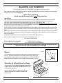
Assembly and Installation
To fully enjoy your new range, it is important that you read this booklet thoroughly.
Note: Please check for any damage that may have occurred during shipping. In the unlikely event that you find any shipping
damage, inform your dealer immediately!
Caution when unpacking:
Lift the range by the bottom skirt, do not lift by nickel trim.
Unpacking:
Note: to avoid injury, please wear safety equipement, glasses and gloves, while you are unpacking your new range.
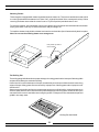
1) Unscrew the 12 screws that hold the crate onto the skid. There are 12 along the bottom and 4 along the top.
2) After the screws have been removed, carefully lift the crate over the stove and set it aside.
3) Next with a pair of tin sips cut the metal banding that holds the stove into place.Caution metal banding is under tension!
4) Carefully remove the metal banding, the 2 boards that where under the banding and the cardbord cap and styrofoam.
5) You are now ready to remove the range from the skid
For 30" units have one person at each end stand beside the skid and carefully lift the range by the bottom skirt, and a third
person pull the skid out from underneath the range. Slowly set the range down on the floor, bending you knee's not your
back!
For 48" units units have one person at each end and one side, stand beside the skid and carefully lift the range by the bottom
skirt, and a fourth person pull the skid out from underneath the range. Slowly set the range down on the floor, bending your
knee's not your back!
6) Finish unpacking the range removing packing tape around the doors and in the oven.
Both 30" and 48" Ranges consist of two main parts:The Range Body, and
The Cabinet / Exhaust Hood
Tools required for assembly:
- Phillips/Robertson Screwdriver
- 5/16" ( 8 mm) wrench or crescent wrench
You must have a qualified electrician connect the new range to be sure all electrical codes and rules are
observed except when range is equipped with a cord and plug
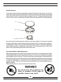
Figure 1
Gliders:
1/8"- 1/4"
The teflon glider should extend beyond the bottom of the leg by approximately
1/8"-1/4". Adjusting levelling bolts in too far will cause the leg to drag on the
floor potentially causing damage to flooring. (see figure 1). Check that gliders
and floor are free of any debris, this will ensure you do not scratch your floor.
Teflon Glider
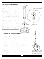
Assembly of Exhaust Hood to Range
Figure 2
See the manual entitled "Cabinet Installation Instructions
for Gas, Electric, Combination and Wood Stoves" which
is included with the cabinet .
(DO NOT REST CLOSET CORNER BRACKETS ON
PORCELAIN SURFACE, DAMAGE TO SURFACE
MAY OCCUR)
2
Positioning the Range
1. When the range is fully assembled, recheck all electrical connections especially between the exhaust hood and the back
of the range. As well, check that all nuts and bolts have been tightened.
2. Ensure teflon gliders and flooring are clean, (as described on page 2 under "Gliders").
3. Caution: On flooring with very rough surfaces or deep, large grooves the appliance may have to be lifted and slowly slid into
position.
4. Put both hands on the trim and carefully push the range into place, make sure floor is clear of all debris. Don't forget to
plug in the main power cord and the exhaust hood power cable and test the operation of the appliance, before the
range is in it's final position. See cabinet installation instructions.
5. To level the range, simply adjust the levelling screws with teflon pads located at the bottom of each leg (the ones you
assembled on page 2 under "Gliders"). Using a 5/16 (8mm) open end wrench turn the adjusting screw clockwise to raise
up the corner, and counter-clockwise to lower the corner. (Don't forget the teflon glider should extend beyond the bottom
of the leg by approximately 1/8"-1/4") Ensure the unit is perfectly level, or utensils may fall of during cooking.
6. Note: On soft kitchen flooring, the weight of the stove may cause slight depressions in the flooring. When the range is in
position and levelled, you may want to place coasters under the teflon gliders of each leg, to protect the floor. Remove the
coasters when moving the range for cleaning or servicing.
Installation Clearances
If the range must stand beside a refrigerator, it is important for proper air circulation, that there be at least 5" of space between the
two appliances.
Do not install range closer than 1/2" from adjacent surfaces.
To eliminate the risk of burns or fire by reaching over heated surface units, installation of cabinet storage space above the surface
units should be avoided. If there is existing cabinet storage space have at least 30 1/4" (768 mm) of clearance. (see fig 3)
For best cooking results, your range should be level. This can be checked with a carpenter’s level on top of the cooking surface
and across the oven rack. If levelling is required, adjust the leveller screws under one or more of the legs (see "Positioning the Range"
step 5).
0
Fig 3 Installation Clearances
0
min
30 1/4"
768 mm
0
0
m in
30 1 /4 "
7 68 m m
1"
25 m m
min 18"
457 mm
0
m in 18 "
457 m m
m in
36 "
914 m m
max
36 "
914 mm
Model 5200 / 5210 48" Installation Clearance
Model 4200 / 4210 30" Installation Clearance
Installation Clearances
Surface adjacent to cook top-left (48") 1” (25mm) Surface adjacent to cook top-right (48") .......0” (0 mm)
Surface adjacent to cook top (30")
0” (0 mm) Surface adjacent to warming oven ...............0” (0 mm)
Cook top to underside of adjacent cabinets ... 18” (457 mm)
Cook top to underside of cabinets .... 30 1/4” (768 mm)
Maximum depth of overhead cabinets ............ 13” (330 mm)
Maximum depth of counters ..................24” (610 mm)
Maximum height of counters .......................... 36” (914 mm)
Rear clearance
0” .........................................(0 mm)
The clearances in the table are also stated on the rating plate and on a reproduction of the plate on
the back page of this manual. (see "installation clearances" diagram)
3
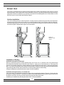
Exhaust Hood
Your range is equipped with a two speed range hood that may be either vented directly to the outside, or may be
installed ventless. A set of exhaust filters are included with your hood. The filters should be cleaned periodically in
soapy water. Extras are available from your dealer or directly from Heartland Appliances Inc. Please order 4 or more
filters at one time to save freight and handling charges.
Ventless Installation
Your unit is already set up for ventless operation. Cooking fumes are drawn through the filters and exhausted
through the rear of the hood, back into the room. Install the exhaust filters in their location under the cabinet by
first removing the light lens. Then on one side, insert one of the filters into the grooves (front and rear of the cabinet)
and slide into place. Repeat these steps for the second filter
Figure 4
Exhaust venting
options
Installation of Ducting
Installation through an outside wall
Remove air deflector (used for ventless operation only). Cut a 3 1/2 x 10 1/2 ( 88.9mm x 266.7 mm) hole through
the wall directly behind the range hood outlet (See Figure 4.), making sure no wall studs are cut. Push range into
position. From outside of the house, measure distance from the siding to the range outlet. Cut duct pipe that length,
plus 1” (25.4mm) for overlap into outlet. Attach vent hood to pipe. Caulk the back of vent hood and around pipe where
it goes through wall and into range hood outlet so caulking seals against outside siding.
Complete installation by following directions under Ventless Installation.
Installation through an attic to an outside wall
If the vent elbows are embedded in the wall, the range may be positioned as shown in Figure 4. Continue the duct
through the ceiling into the attic. Terminate duct either on an outside wall just below the sofit using a vent hood or
through the roof with a roof cap. Seal with caulking around and under cap or hood.
Complete your installation by following directions under Ventless Installation.
4
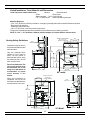
Vented Installation, Tools, Material, and Dimensions
Tools required to install vented hood:
- Hammer
- Slot screwdriver
- Pliers
- Electric drill
- Measuring tape - 3/32” (3 mm) Drill bit
- 1/2” (13 mm) Drill bit - Sabre saw OR Keyhole saw
Materials Required:
- 3 1/4" x 10" (82.55 mm x 254 mm) metal duct—enough to go through wall or attic to outside. Elbows as required.
- Roof cap or wall venthood
- Caulking to seal around duct
- #6 x 1/2” (82.55 mm x 254 mm) sheet metal screws
The above are standard parts and are available at any hardware store or heating contractor.
NOTE: A 3 1/4" x 10" (82.55mm x 254mm) exhaust adaptor is included with the exhaust hood.
Venting Safety Guidelines
R an ge H oo d O utlet
3 1/4" x 1 0"
8 3 m m x 25 4 m m
1 4.0 "
355 m m
Installation must be done in
accordance with all local and
national codes.
4 3/4 ”
12 1 m m
56 "
1 422 m m
74 9 m m
Use only materials which
conform to local codes in
effect. Be sure power is
disconnected before doing
any electrical work. All duct
work must be metal.
20 "
50 8 m m
G as Inlet-1/2” N PT
66 1/ 4"
16 82 m m
Ov en E xha ust
36 1/8 ”
91 7 m m
E x h a us t H o o d In
(f em al e rece p tac le )
30 ”
76 2 m m
Do not use plastic duct. The
range hood should never
be exhausted into a wall
cavity or an attic where an
accumulation of grease
could become a fire
hazard.
P o w e r C o rd
39 3 /4 "
47 1/2 " 10 10 m m
120 7 m m
28”
711 m m
48" model
R ange H o od O u tle t
14 7 /8 "
37 8 m m
When the installation is
completed, turn on the fan
and make sure that there are
no obstructions in the duct.
3 1/4"x 10"
83 mm x 254 m m
14 .0 "
35 5 m m
2 9 1 /2”
787 mm
56 "
1 42 2 m m
6 6 1 /4 "
1 68 2 m m
6 2 3 /8 "
1 58 5 m m
36 1 /8 "
91 7 m m
34"
864 mm
3"
76 mm
29 3 /4 "
7 56 m m
30" Model
5
28”
7 11 m m
Important Safety Instructions
1. PROPER INSTALLATION—BE SURE YOUR APPLIANCE IS PROPERLY INSTALLED AND GROUNDED BY A
QUALIFIED TECHNICIAN. Have the installer show you the location of the circuit breaker or fuse. Mark it for future
reference.
2. Never use your appliance for warming or heating the room. Use only for its intended use as described in this manual.
3. Do not leave children alone. Children should not be left alone or unattended in area where appliance is in use. Children
should never be allowed to sit or stand on any part of the appliance.
4. Do not allow children to play with controls or any part of appliance.
5. Do not climb, stand or hang on the appliance.
6. Wear proper apparel—loose-fitting or hanging garments should never be worn while using the appliance. Flammable
material could ignite on contact with hot surface units and cause severe burns.
7. User servicing—do not repair or replace any part of the appliance unless specifically recommended in the manual.
All other servicing should be referred to a qualified technician. Before performing any service, switch off circuit breaker
or remove fuse.
8. Storage in or on appliance—flammable materials should not be stored in an oven, near surface units or in range
cabinet.
9. Do not use water on grease fires – never pick up a flaming pan - smother fire or flame by covering pan with a well fitting
lid, cookie sheet, metal tray or use dry chemical or foam type extinguisher.
10. Use only dry potholders—moist or damp potholders on hot surfaces may result in burns from steam. Do not let
potholder touch hot heating elements. Do not use a towel or other bulky cloth in place of potholder. Such materials
could catch fire on hot surface unit.
11. Do not let cooking grease or other flammable materials accumulate on the cooktop.
Oven Safety
Do not touch heating elements or interior surfaces of oven—heating elements may be hot even though they are
dark in colour. Interior surfaces of an oven become hot enough to cause burns.
During and after use, do not touch, or let clothing or other flammable materials to contact heating elements or interior
surfaces of oven until they have had sufficient time to cool.
Other surfaces of the appliance may become hot enough to cause burns—among these surfaces are, for example, oven
vent openings and surfaces near these openings, oven doors.
1. Use care when opening door—let hot air or steam escape before removing or replacing food.
2. Do not heat unopened food containers—buildup of pressure may cause container to burst and result in injury.
3. Keep oven vent ducts unobstructed.
4. Placement of oven racks—always place oven racks in desired location while oven is cool. If rack must be moved while
oven is hot, do not let potholder contact hot heating element in oven.
5. Do not use aluminum foil to linethe bottom of the oven,it could result in a risk of electric shock or fire.
6
Exhaust Hood Safety
Caution:
Do not store items of interest to children in cabinet above the range or on top of range cabinet.
Children climbing on range to reach items could be seriously injured.
1. Clean exhaust hood frequently—grease should not be allowed to accumulate on hood or filter.
2. If foods catch fire under the hood, turn the fan off. The fan, if operating may spread the flame.
Warming Oven Safety
Caution:
Do not store items in the warming drawer, items stored there could be damaged if the warming control
is turned on.
Self Clean Safety Instructions
Read the instructions below and the appropriate timer instructions before attempting to operate.
Do not touch heating elements or interior surfaces of oven—heating elements may be hot even though they are dark in
colour. Interior surfaces of an oven become hot enough to cause burns.
During and after use, do not touch, or let clothing or other flammable materials to contact heating elements or interior surfaces
of oven until they have had sufficient time to cool.
Other surfaces of the appliance may become hot enough to cause burns—among these surfaces are, for example, oven vent
openings and surfaces near these openings, oven doors.
1. Remove utensils and cookware from the oven. Oven racks and rack supports should be removed from the oven. Racks and
supports left in the oven during self clean will become discoloured, but it will not affect the protective coating.
2. Remove all utensils and food from cooktop. Note: use of surface elements while range is self-cleaning is NOT
RECOMMENDED.
3. Remove all contents from the storage drawer. This includes plastic or aluminium utensils and any utensils with plastic parts
that can become over heated and melt.
4. In 48" ranges remove all contents from the storage area . This includes plastic or aluminium utensils and any utensils with
plastic parts that can become over heated and melt.
5. DO NOT clean the gasket. The door gasket is essential for a good seal. Care should be taken not to rub, damage or move
the gasket.
6. Never use a commercial oven cleaner in a self cleaning oven. This will damage the finish.
7. Make sure the convection fan is off. The convection fan switch must be turned off at the control panel at the timer. (The oven
light will automatically go off when the door is closed.)
7
Cooking Controls
Features
The cooking controls are located on the right
hand side of the cooktop; these controls
offer an infinite number of heat settings for
ease and accuracy in cooking and baking.
Control Panel
Sealed Burner Features
A) Centre Burners - are two maximum
8,000 BTU (2.34 kW) (L/P
7,000BTU)with simmer of 600
BTU (.2 kW) sealed gas burners
,easy clean, for medium duty
cooking tasks
B) Left Burners - front sealed burner
is maximum 10,000 BTU (2.93
kW) )(L/P 9,000BTU) with simmer
of 1000 BTU (.3 kW) and rear is
maximum 8,000 BTU (2.34 kW)
(L/P 7,000 BTU) with simmer of
600 BTU (.2 kW) accurately
maintain temperature.
B
A
Utensil
Drawer
C
D
E
F
Burner and
Oven Controls
Storage
G
He
ea
ea
arrt
rt
tlla
la
an
nd
C) Right Burners (48" models only) front sealed burner is maximum
10,000 BTU (2.93 kW) )(L/P
9,000BTU) with simmer of 1000
BTU (.3 kW) and rear is maximum
8,000 BTU (2.34 kW) (L/P
7,000BTU)with simmer of 600
BTU (.2 kW) , one for large jobs,
one for small, easy clean.
H
I
Figure 5
(48" Model shown)
D) Gas Burner Controls - allow an infinite selection of cooking temperatures, 4 controls on 30" models and
6 controls on 48" models. All models feature "auto-reignition", which means if for any reason the flame
goes out, it automatically begins to spark to re-ignite the burner!
Oven Features
E) Oven temperature control - With bake control, broil control
F) Self Clean latching handle - slides to the right to lock the oven door during the self clean cycle. (self clean
models only). Latch must not be used to lock door during regular cooking functions or damage to latch
may occur.
G) Convection oven:- baking, broiling
- timed baking, broiling
- convection baking, broiling
- timed convection baking, broiling
- 4 position racking
- 4 cubic feet of energy efficient baking area (.11 cubic meters)
- low maintenance high temperature self clean oven (self clean models only)
8
Warming Drawer Features
H) Located under the main oven, glides open for easy access
- sliding humidity control
- large 1 cubic foot warming area
I) Thermostatic temperature control, located just right and behind the warming drawer
Storage Features
(48" models only)
- Rack storage area: ideal for oven racks and baking trays.
- Utensil drawer: Unique storage space, keeping necessities within easy access
Control Panel
PA
U
T
O
J
K
L
M
Please Note: Warming oven is not affected by timer settings
Clock Control Panel
The timer and control panel is concealed behind the cabinet door for standard and self clean models. Note: Warming Oven is
not timer controlled
J) Digital Timer - With minute minder and automatic start and stop cooking features.
K) Rocker Switch controls the overhead light under the exhaust hood.
L) Rocker Switch controls convection fan for convection baking/broiling.
M) Three position switch controls the high / low for the exhaust fan. Center position is “OFF”.
9
Control Panel Layout
The control panel is laid out in a straight line and each control is identified by a
graphic on the right side of the knob.
Model 4200/4210
Control Panel
Model 5200/5210
Control Panel
Left Rear Burner Control
- Medium
Left Rear Burner Control
- Medium
Left Front Burner Control
- Large
Right Rear Burner Control
- Medium
Centre Rear Burner Control
- Medium
Left Front Burner Control
- Large
Centre Front Burner Control
- Medium
Right Front Burner Control
- Medium
Right Rear Burner Control
- Medium
Bake/Broil Oven Control
(see page 14)
Right Front Burner Control
- Large
Warming Drawer Indicator
Light (see page 13)
Bake/Broil Indicator Light
Bake/Broil Oven Control
(see page 14)
The operation of the controls are described
in the following pages.
Warming Drawer Indicator
Light (see page 13)
Bake/Broil Indicator Light
10
OPERATION
Top Burner Operation
Lighting the Top Burners
Your range is equipped with a spark ignition system that is electrically operated. You need only to push in and turn the knob
to any position and the burner will light. When you turn the knob, you will hear a distinct clicking noise. After the burner lights,
the clicking noise will stop. Note: when lighting any one burner, all burners will spark, but only the burner that you have selected
will light. All models feature "auto-reignition", which means if for any reason the flame goes out, it automatically begins to spark
to re-ignite the burner!
See page 12 for manual lighting procedure.
6 (HI) - Quick start for cooking, brings water to
boil.
5 (MED HI) - Fast fry, pan broil, maintain fast boil
on large amount of food.
4 (MED) - Saute and brown; maintain slow boil on
large amount of food.
3 (MED LOW) - Cook after starting at MAX; cook
with little water in covered pan.
2-1 (LOW) - Steam rice, cereal; maintain serving
temperature of most foods.
Top Burner Control
For safety reasons, always adjust the burner controls so that flames do not extend beyond the
edges of pots, pans or other cooking utensils.
Large pots or other over sized cooking utensils may cause random sparking from the burner. To
avoid this condition lower the flame size or use smaller sized cooking utensils.
Do not use a griddle directly on top of grates. To avoid random sparking, please use the Heartland
Griddle Pan Kit for Classic Ranges part #7602 (complete with griddle pan support) may be
purchased from your dealer or directly from Heartland.
11
Power Failure Operation
If electrical power is interrupted in your area, you can still cook meals on the top burners of your
Heartland gas /electric range. Of course your oven will be inoperable, however, by following
these simple directions you will be able to use the top burners without the benefit of electricity.
Caution: make sure your hands and clothing are clear of the burner you are lighting!
Manually Lighting the Top Burners
1) Remove cast grate, for unobstructed access to the burner head.
2) Hold a flame source to the desired burner head. We recommend a barbecue lighter to use
as a flame source.
3) Push in and turn the corresponding control knob to the medium setting.
4) After the burner lights, adjust flame size as required.
5) Carefully replace cast grate, keep fingers clear of the flame.
Please note that the "auto reignition" feature will not function without electricity,
therefore pay close attention to any burners in use while electrical power is interrupted!
When lighting top burners manually, set
control to the medium setting to prevent
potential injury from the flame when
replacing the grate.
Top Burner Control
12
Warming Drawer Control and Operation
To activate the warming drawer, first find the temperature control located
beside the warming drawer behind the drawer door.
Select a temperature level from low to high.("-" to "+) The temperature is
infinitely variable and ranges from 130°F to 220°F. (54°C to 104°C)
When the control is in use the indicator will glow until the temperature level
has been reached, then it will cycle on and off to maintain temperature.
Warm rolls, breads, vegetables, meats etc.
as well as plates on HIGH.
The warming drawer also features a humidity
control located along the top of the drawer
door. When the control is positioned to the
left stop, the humidity is retained in the warming drawer. If positioned to the right stop,
then air is able to circulate allowing humidity
to escape.
warming oven indicator light located right
and below main oven control
Too keep moisture in, close humidity control. To keep things crisp, open humidity control. Proof ( rise)
bread or pizza dough on LOW with humidity control closed
Heeart
H
rtllla
art
nd
aan
n
C lo s
ed
Op en
temperature control
humidity control
sliding warming drawer
Please note: Do not use the drawer as storage. Items stored there may be damaged if the temperature
control is activated. Warming drawer may be removed for easier cleaning (see "Warming Drawer
Removal" page 31")
13
Bake - Broil Control
Warming drawer
indicator light
Main oven
indicator light
Oven Bake/ Broil Control
Baking
To bake, push down and turn the oven control counter clockwise to any desired temperature.
When baking is selected, the indicator light under the bake symbol lights up, and the bake
element will activate. The element will then cycle on and off to maintain an average temperature
in the oven
Please note: that when oven is turned on to preheat, the first cycle may exceed set temperature
- please allow oven to cycle on/off before placing food in oven.
The temperature is infinitely variable between temperatures 150°F and 550°F (65°C and 290°C.)
Broiling
(do not broil with door open)
To activate broil (top element), turn oven control to broil . When broiling is selected, the indicator
light, lights up. To de-select broiling, turn the oven control knob to a temperature setting, which
resets the control to baking mode. If knob is turned past the "BROIL" position - element will not
operate. Turn back to broil position.
14
Oven Operation
Before You start:
1. Remove the oven racks and oven rack supports and clean with soap and water. (see
interior oven rack and rack support removal pg. 29 ).
2. Unwrap broiler pan and clean with soap and water.
3. Clean oven with soap and water, making sure that all adhesives have been removed.
4. Set time on the clock, clock must be set or oven will not function! (see timer section
pg. 17).
5. Turn oven on to 500°F (260°C) for 30 minutes to burn off bonding agents in the insulation.
There will be an unpleasant odour and some smoke, which is unavoidable.
Getting to Know Your Oven
The oven light will automatically activate when the oven is opened and deactivate when the
oven door is closed.
Also if the oven is set for convection mode, then the convection fan will deactivate when the
oven door is opened, and activate when the oven door is closed.
The oven features multi level regular baking/broiling in timed or un-timed modes. For energy
efficient batch baking, choose convection baking, which allows you to bake on multi levels
simultaneously. For traditional baking the convection feature should be OFF.
Your oven has a temperature range of 150° F to 550° F (65°C to 290°C). The oven Cycling
Light glows until oven reaches the high end of heating cycle, then cycles off and on during
cooking. The average of the high and low levels of the heating cycles will be approximately
within 30° F of selected temperature. This temperature fluctuation is normal and standard
in the appliance industry. See pages 19 and 21 for recommended baking and roasting times
and temperatures.
Note:
1) Self Clean Models Only - Do not engage the self clean oven door latch when not in
self clean mode, as it is possible the oven door safety interlock will activate at high
oven temperatures and damage could occur to the locking mechanism.
2) See pages 20 through 21 for recommended broil times and settings.
3) Temperatures in ovens may shift over time and it is natural for the user to gradually adapt
cooking times accordingly. Then, when baking in a new oven with proper calibration, results
may not be as expected based on previous baking habits. Oven cavity sizes also vary from
manufacturer to manufacturer and could affect cooking results slightly. Therefore, it may
take some time to familiarize yourself with your new oven and some adjustment in cooking
times may be necessary.
15
How to Select Cooking Methods
Standard Baking - To bake, turn the oven control to any desired temperature between 150°F to 500°F (65°C AND 290°C).
When baking is selected, the indicator lights up, and the bake element will activate. Always preheat the oven
approximately 5-10 minutes. During cooking, the bake element will cycle on and off to maintain temperatures. Do not
rotate control past 500°F (290°C) for bake as this is the broil position and only top element will come on.
Standard Broiling - To activate broil (top element), turn oven control to broil (end stop position). When broiling is
selected, the indicator lights up. At this setting the broil element comes on and stays on. To de-select broiling,
turn the oven control knob to a temperature setting, which resets the control to baking mode. When broiling, the oven
door should remain closed, and the grease filter installed. Please do not leave food unattended while broiling as it may
smoke or even burn.
Convection - when the rocker switch in the exhaust hood is set to this symbol, the convection fan has been
activated. The convection fan can be operated in three modes.
1) convection baking.
2) convection broiling.
3) convection drying.
Note: When using convection baking, please ensure the grease filter is not installed, otherwise, air will
not be able to properly circulate in the oven. Filter must be installed for convection broiling/roasting.
Convection Baking - select a temperature on the oven control and then select "
Oven is now in "Convection Bake Mode".
" below the rocker switch.
Convection Broiling - select "broil" on the oven control and select "
" below the rocker switch. The oven
needs to remain closed while in Convection Broil Mode. When broiling, please take care not to leave food
unattended as it may smoke or burn.
Convection Drying - leave temperature control at "OFF" and select "
fan has been activated and oven is now ready to dry spices or fruits.
"below the rocker switch. The convection
For time bake, when the rocker switch is set to this symbol "
" and the timer and temperature controls are set,
the fan will then automatically activate when the selected time has been reached. For more detail on "Time Bake"
see page 18.
16
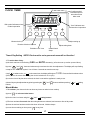
CLOCK/ TIMER
Cooking symbol
indicates oven is in
auto shut off time
bake mode
A
U
T
O
Bell symbol indicates minute
minder in operation
"Auto" indicates auto
activate timer in operation
STOP
T IM E R
S TO P
Adjust setting up
Minute minder
Duration of bake or S/C time
Adjust setting down
End bake or S/C time
Initiate/Cancel
Setup
Time of Day Setting NOTE: Clock must be set or your main oven will not function!
1. To set the time of day:
a) the clock read-out will be flashing "0:00" and "AUTO" alternately.( at first time set up or after a power failure)
b) press "
" and "
" buttons simultaneously to activate the clock time adjustment. The display will stop flashing
except for the ""AUTO" symbol. You will have 3 seconds to start the next step.
c) tap"
" to advance time, or "
" to decrease time, the display will begin at "12.00". Press and hold to advance time
quickly. Set to the correct time of day (the clock is based on a 12 hr cycle).
d) once the time of day has been entered, the clock is set and the appliance is ready to use.
e) time of day may be adjusted at any point by pressing the"
" and "
" buttons and then pressing "
" or "
buttons.
Minute Minder
1. To set timer: (the minute minder can be at any time even when in timer modes)
a) press “
“ the minute minder button.
b) Set the timer in minutes using the "
" and “
“ setting buttons.
c) The timer activates 5 seconds after the setting buttons are released, and returns to dime of day mode.
d) when the set time has been reached the timer will sound, 2 distinct beeps.
e) to see time remaining on timer press “
“ at any time.
17
" setting
2. To cancel minute minder operation:
a) press “
“.
b) press “
“ setting button and set to zero.
c) then press “
“ cancel button and the display will return to time of day mode.
Time Bake (for main oven only)
1. To set time bake:
a) if convection is desired activate the convection fan rocker switch marked "
b) press the “
" on the control panel below the timer.
“ bake duration button.
c) use the "
" and “
“ to set the length of time you want the oven to be in operation. (The "
" and “
buttons work in 1 minute intervals). The oven will now turn off after the time entered has elapsed.
d) to have the oven turn on at a specific time, next, press the “
e) use the "
" and “
STOP
“ setting adjust
“ end bake time button.
“ to set the actual time of the day you want the oven to shut off. After 5 seconds the display will
return to time of day mode. The
"AUTO" indicator will light up, showing the timer is in operation, and the “
“ symbol
will shut off, indicating the oven is off until the timer activates the oven.
f) set Temperature Dial to desired cooking temperature. The timer calculates the start time by subtracting the cook time from
the time of day you want the oven to shut off.
g) when the bake cycle begins, the “
“ symbol will light up showing that the oven is in operation.
h) when the time bake cycle is complete, the "AUTO" indicator will flash, the “
“ will shut off indicating the oven is off
and the timer will sound (4 distinct beeps).
i) the timer will sound until the “
work until the and the “
“ cancel button is depressed. The "AUTO" indicator will flash and the oven will not
“ button is depressed a second time. Remember the turn off your oven control.
2. To cancel time bake:
a) anytime during the time bake cycle depress the “
“
“ bake duration button and set the time to zero, and depress the
“ cancel button to return to time of day mode.
b) the minute minder can still be used during the time bake cycle.
18
General Cooking Guidelines
Standard & Convection Cooking
Standard Cooking:
This is the traditional “radiant heat” style of cooking. You may choose this method of
cooking for your tried and true recipes. As with all radiant style ovens, it will be
necessary to preheat the oven, especially for baked goods. When roasting meats from
frozen to finish, usually preheating is not required. However allow 1/3 to 1/2 more
cooking timedepending on the size of the cut. To assure desired degree of doneness,
use a meat thermometer for meats and poultry.
Radiant Heat Pattern Note: Bake and Broil elements are independently controlled. Broil
Diagram shows how
element will not turn on when bake element is used.
heat is radiated from the
elements, during the
cooking process
Convection Cooking:
Convection Air Pattern
Diagram shows how heat is
circulated from the convection fan,
distributing heat evenly around the
food, during the cooking process.
Convection means conveying. A fan at the back of the oven circulates the hot air thus
cooking foods from all sides, sealing in juices. The circulating air penetrates food faster
therefore you may want to cook foods for less time at the usual temperature or reduce
the temperature by 25 F/15 C and cook for approximately 10% less time or as indicated
in our cooking guides on pages 20 and 21.
With convection cooking you can cook on more than one rack at a time thus saving
time and energy. Occasionally if cooking on multi-levels you may need to remove one
pan sooner than the others. You can even cook a complete meal at the same time as
long as you choose items that cook at the same temperature, as there is no flavour
transfer; however we do not recommend an item that may spatter to cook on the same
shelf as a dessert. Be sure to stagger pans if possible on multi-levels so that one is
not directly over the other and leave at least 1" (2.5 cm) of space between the pans.
Do not place large pans directly in front of fan, at the back of oven, as this may block
the air circulation.
Note:
Please ensure grease filter is not installed when selecting
convection, otherwise fan will not circulate air properly
Convection Roasting:
This method of cooking uses both hot air and radiant heat, and is similar to rotisserie
cooking, where high heat is applied quickly and evenly around the meat, but instead
of rotating, hot air circulates around the meat.
Before beginning convection roasting, insert the grease filter at back of oven and insert
the optional raised roasting rack into broiler pan and rack. Place the cuts of meat or
poultry fat side up, uncovered on the raised roasting rack. This allows the air to circulate
around the roast, sealing in the juices. Do not use deep roasting pans or baking pans
with high sides , as air cannot circulate around the food. Insert a meat thermometer into
the thickest part of the meat, avoiding bones to accurately determine doneness.
Standard Broiling:
This method of cooking is used to transfer high heat over a short period of time to placed
in close proximity to the broiler element. Usually used to brown the surface of food,
such as meringues, steaks and roasts. Place meat on the broiler pan (add water to the
bottom of the pan to reduce smoking) and place on the third or fourth rack depending
on the food and your personal tastes. Please do not leave food being broiled unattended
- excessive smoke or burning may occur. Refer to broiling tips & cooking chart on page
21.
19
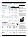
Cooking Guide
This chart is a referance guide only, as variables such as size, tempature and individual preferances may affect the cooking time.
Recipe or package directions should always take precedence. Keep a record of your results, preferred tempatures and times.
General Cooking Tips & Preferences
Meat Roasting Guide:
Oven Tem perature for R egular or
C onvection R oasting
D egree of
D oneness
Foods
Internal
C ooking
Tem perature
°F
°C
M inu tes p er lb (p er kg )
°F
°C
325
160
20-25 (45-50)
140
60
B eef
S irloin or R ib R oas ts
R are
R um p, R ound (roast)
M edium
325
160
25-30 (55-60)
160
70
W ell done
325
160
30-35 (65-70)
170
75
R are
275
140
40-45 (80-85)
140
60
M edium
275
140
45-50 (90-95)
160
70
M edium
325
160
30-35 (65-70)
160
70
W ell done
325
160
35-40 (75-80)
170
75
325
160
20-25 (45-50)
160
70
·Place oven rack in correct position before
preheating oven.
·After reading the thermometer insert another
1/2"/1 cm and read again. If it reads lower than the
first then continue cooking.
·Meat continues to cook after removal from oven Allow meat to stand about 15- 20 minutes before
carving
Convection Cooking:
·For convection roasting, insert the grease filter in
back of oven and place the raised roasting rack
over the 2 pc. broiler pan. (broiler rack is necessary
to prevent spattering).
Veal
Leg, Loin, R ib R oasts
Pork
Leg or Loin R oast
C row n R oas t
325
160
15-20 (25-30)
160
70
S houlder R oast
325
160
25-30 (35-40)
160
70
325
160
10-15 (22-25)
140
60
R are
325
160
20-25 (45-50)
140
60
M edium
325
160
25-30 (55-60)
160
70
H am
·Convection cooking may cook faster; times may
often be reduced up to 10 minutes per lb (.5 Kg) for large items meat should be checked shortly
before the suggested minimum cooking time.
·Recommended for “all” tender meats to give a
brown outside with a juicy, tender inside
·For extra browning brush lean meats with oil
·Place all roasts fat side up on raised roasting rack
S m ok ed, pre-cook ed
Lam b
Leg
Leg, S hould R oasts
W ell done
R ack (R oas t)
325
160
30-35 (65-70)
170
75
R are
400
200
10-12 (22-25)
140
60
M edium
400
200
12-18 (25-38)
160
70
4
3
2
1
Oven Rack
Positioning
Figure 1
Poultry Roasting Guide:
O ve n Tem perature for S ta ndard or
C onvection R oast
Foods
Internal
Cooking
Tem perature
General Cooking Tips & Preferences
°F
°C
M inutes p er lb (per Kg)
°F
°C
·Place oven rack in correct position before
preheating oven. Rack position is 2 or 3 for standard
roasting & rack 1 for convection roasting (refer to
Figure 1)
Turk ey
Lbs
Kg
S tuffe d
6-8
3 - 3.5
325
160
30-32 (6 0-65)
180
82
·For extra browning brush skin with oil
S tuffe d
10 - 12
4.5 - 5 .5
325
160
23-25 (4 5-50)
180
82
S tuffe d
16 - 22
7 - 10
325
160
15-20 (3 0-35)
180
82
6-8
3 - 3.5
325
160
25-30 (5 0-55)
170
77
·Insert a meat thermometer into the inner thigh
(avoid touching the bone) to accurately determine
doneness. Take a second reading inserted another 1/
2"/1 cm and read again , if it reads lower than the
first then continue cooking.
U nstu ffed
10 - 12
4.5 - 5 .5
325
160
18-23 (3 5-40)
170
77
U nstu ffed
16 - 22
7 - 10
325
160
13-15 (2 5-30)
170
77
1
50 0 (g)
325
160
60-75 m in . total
170
77
Lbs
Kg
U nstu ffed
P arts -1/2-B oneles s B reas t O R Leg
Chic ken
C apon
5-8
2.3 -3 .6
325
160
18-20 (4 0-45)
170
77
C hic ke n, W hole , U ns tuffe d
3-4
1.3 -1 .8
325
160
20-25 (4 5-50)
170
77
325
160
18-20 (4 0-45)
170
77
C hic ke n, Q uarters
20
·Poultry continues to cook after removal from oven
Allow to stand 15-20 minutes before carving.)
Convection Roasting:
·Insert the grease filter in back of oven and place
the raised roasting rack over the 2 pc. broiler pan
(broiler rack is necessary to prevent spattering).
·Convection cooking may be faster; times may
often be reduced up to 25% - for large items check
shortly before the suggested minimum cooking time.
Cooking Guide
This chart is a referance guide only, as variables such as size, tempature and individual preferances may affect the cooking time.
Recipe or package directions should always take precedence. Keep a record of your results, preferred tempatures and times.
General Cooking Tips & Preferences
Broiling Guide:
Foods
D egree of D oneness
Thickness
A pproxim ate
Tim e
R are
3/4 - 1 inc h (2 c m )
5-6 m in/s id e
M edium
3/4 - 1 inc h (2 c m )
7-8 m in/s id e
W ell done
3/4 - 1 inc h (2 c m )
6-8 m in/s id e
until no longer pink
3/4 - 1 inc h (2 c m )
5-6 m in/s id e
M edium R are
1 inc h (2 c m )
5-7 m in/s id e
·Insert the grease filter (provided) on to the fan shield to
prevent grease build up.
·Allow the oven to preheat for 8 minutes
·Prepare meat, allowing frozen meat to thaw before
broiling.
B eef
S teak s
G roun d B e ef P a tties
Pork
P ork C hops or K a bobs
Lam b
Lam b C hops or K a bobs
C hic ken
C hic ke n P a rts
B oneles s B reas ts
until juic es ru ns c lear
25-40 m in utes
until no longer pink
6-8 m in/s id e
·Slit the fat around the edge of the meat about every inch,
to prevent curling. Arrange meat on the broiler pan.
·Always use the broiler pan and rack supplied.They are
designed to allow fats to drip into the pan, reducing
smoking while the food is cooking. If desired, the broiler
pan may be lined with foil and the broiler rack may be
covered with foil. However be sure to mould the foil to the
broiler rack and cut slits in the foil to conform to the slits
in the rack to allowjuices and fat to drain into the pan.
·Broil meat on rack of broiler pan placed on oven shelf
in third or fourth position (refer to Figure 1) about 4-5
inches (10-12 cm) below the top element.
·The closer the meat is placed to the broil element, the
faster the surface browns. For rare meat, preheat the
broiler unit and place the meat as close to the unit as
possible.
·The further away the meat is placed, the slower the
surface browns and the more well done the meat will be.
Fis h
W hole or S teak s
flakes w ith a fork
B oneles s Fillets
flakes w ith a fork
5-10 m inu tes
Lobs ter T ails, Th aw ed
8-10 m inu tes
Caution: Accessible parts may become hot when the broiler is in use. Children should be kept away.
·Turn meat with tongs, not a fork so as not to pierce meat
and lose juices.
·Keep oven door closed for broiling.
Baking Guide:
F ood s
·A small amount of water placed in the broiler pan will
reduce the smoke and splattering from hot
drippings.
S in g le R a c k M u ltip le R a c k
P o s itio n fo r P o s itio n fo r
S ta n d a rd o r C o n ve c tio n
C o n ve c tio n
O N LY
C o o kin g C o n ve c tio n
S ta n d a rd
T im e
Te m p e ra tu re
Te m p e ra tu re
F
C
M in u te s
F
C
C o o kin g
T im e
M in u te s
B re a d s
Ye a s t Lo a f
2
N o t a d vise d o n
m u ltip le ra c ks
400
200
30 - 40
375
190
20 - 30
Ye a s t R o lls
2 or 3
2 & 4 or 1 & 3
375
190
15 - 20
350
180
6 - 10
F o c a cc ia o r P iz za
1 or 2
N o t a d vise d o n
m u ltip le ra c ks
400
200
15 - 20
400
200
12 - 18
M u ffin s
2 or 3
2 & 4 or 1 & 3
425
220
20 - 25
400
200
12 - 20
Tea B is cu its
2 or 3
2 & 4 or 1 & 3
450
230
12 - 15
425
220
8 - 12
General Cooking Tips & Preferences
·Place oven rack in correct position before preheating oven
(refer to Baking Guide and Figure 1on pg. 24)
·Bake most frozen foods that are in foil containers on the
aluminum baking sheet supplied with oven as shiny
surfaces reflect the heat.
Piecrusts:
- Dull metal pans absorb and conduct heat the best.
- Dark finishes and glass absorb more heat, cooking
faster and resulting in darker crusts.
- If using shiny aluminum foil pans, place on aluminum
baking sheets to conduct heat better for bottom crust.
-Shield edges with foil if getting too brown before
completely cooked
·For Layer Cakes single rack convection is recommended
C a ke s
L a ye r C ak e M ix e s
2 or 3
N o t a d vise d o n
m u ltip le ra c ks
340
175
30 - 36
300
150
25 - 30
·For Angel Food Cakes convection is recommended with 1
or 2 cakes
A n ge l F o o d M ix e s
1
N o t a d vise d o n
m u ltip le ra c ks
325
160
55 - 60
300
150
40 - 45
·If using insulated baking sheets, items may take longer
to cook.
2 or 3
2 & 4 or 1 & 3
350
180
20 - 25
325
160
15 - 20
1 or 2
N o t a d vise d o n
m u ltip le ra c ks
400
200
8 - 10
400
200
8 - 10
Convection Baking:
·Generally lids or foil covering are not recommended except
for moist casseroles (e.g. lasagna) which can be covered
half way through the cooking time to prevent drying out.
1
N o t a d vise d o n
m u ltip le ra c ks
C u p ca k e s
P ie s
S h ells w itho u t F illin g
D o u b le C r us t w ith F illin g
15
230
450
- th e n lo w e r in g to :
190
30 - 40
375
15
220
425
- th e n lo w e r in g to :
180
20 - 25
350
C o o kie s
D ro p o r S u g a r
2 or 3
2 & 4 or
2, 3 & 4
350
180
10 - 12
325
160
8 - 10
R o lle d
1 or 2
2 & 4 or
2, 3 & 4
375
190
8 - 10
350
180
8 - 12
21
·For quick breads (e.g. banana or zucchini loaves) do not
reduce temperature since they are very dense and moist.
Be sure to insert a cake tester or toothpick to see that
center is cooked.
·For cookies, tea biscuits and rolls, use aluminum baking
sheets that are supplied with stove, do not use larger ones
or ones with sides. This is so that the air can circulate
evenly. When multiple racks are cooked at once, middle
rack may take a few minutes longer to cook.
Care and Cleaning
Porcelain and Painted Enamel
Keeping it clean
The porcelain and painted enamel is very serviceable and simple to clean, but because it is
glass, it will not withstand rough handling or abuse. Avoid extreme variance of temperatures
on porcelain. Porcelain is glass and sudden changes in temperature may cause cracking. To
clean porcelain surfaces, use warm, soapy water, glass cleaner or non abrasive cleaner and
a soft cloth. Avoid abrasive cleaners.
If any acid based food or liquid, such as lemon juice or tomato juice, is spilled on the range, wipe
it at once to prevent staining.
Note: Red appliances only - a red wax coating has been added for preparation purposes which
may wear off during cleaning - this is normal and does not affect finished product.
Oven & Warming Drawer Cleaning
Standard Oven/Warming Drawer (non self clean)
Your range must be kept clean and free of accumulations of grease or spillovers which may
ignite. This is most important in the oven compartment. When cleaning the oven or warming
drawer, make sure it is turned “Off” and is cool. For simple spills, clean with a strong solution
of detergent, then wipe with a clean damp cloth and dry.
When food or grease has burned on the lining, apply a strong oven cleaning compound. Follow
directions on the package, but avoid applying a strong cleaner to the front flanges or sides of
end panels because it may destroy the door seals or plated surfaces. Under no circumstances
should an oven cleaner be used in a hot oven or warming drawer.
Oven racks, oven rack supports, broiler pan rack, oven bottoms, and broiler pan are all
removable for easy cleaning. The warming drawer is also removable for easier cleaning (see
page 31 for warming drawer removal instructions). Oven racks may be cleaned in your sink
with dish cloth and detergent. If spillage has remained on the racks for an extended period,
more vigorous cleaning with a steel wool soap pad may be required.
Self Clean Oven
Self Cleaning requires the use of the clock timer. Read the instructions below and the
appropriate timer instructions before attempting to operate. After the self clean cycle is
completed, the shiny luster of the oven cavity may diminish in some areas, this is not uncommon
and it does not affect the operation or performance of the range
1. Remove cookware from the oven. We recommend that the oven racks also be removed.
If they are left in the oven, the racks will become discoloured and rough after cleaning, but it will
not affect the protective coating. Wiping the racks down with a bit of vegetable oil can help with
the ease of sliding the racks in and out.
2. Remove any items from the warming drawer(as well as the side storage area and utensil
drawer in the 48" models). This includes utensils with plastic parts that can become overheated
and melt.
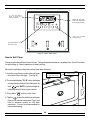
22
3. Remove all utensils and food from cooktop.
4. Wipe up heavy soil on the oven bottom.
5. Clean spills on oven front frame (A) and the oven door outside of the gasket area (B) with a damp
cloth. These areas are outside the self cleaning area and soil will become baked on.
A-oven front frame
Do not clean gasket
B-outside oven door gasket
area
DO NOT under any circumstance use a commercial oven cleaner, or surface coating
for ovens on a self clean oven. This will damage the finish.
DO NOT clean the gasket
DO NOT use surface elements while range is self-cleaning
DO NOT run the convection fan during self clean mode. The convection fan switch
must be turned off at the control panel in the exhaust hood. (The oven light will go off
automatically when the oven door is closed)
23
"P 1.30" and "AUTO
lights up when self
clean is activated
A
U
T
O
T IM E R
display will show time,
1:30 to start, adjustable
to 3:00 hours maximum
STOP
press "+" to increase
self clean time
press bake button to set
self clean mode
Figure A - Control Panel Layout
How to Self Clean
The recommended self clean time is 3 hours. The cycle can be set however, anywhere from 1 hour 30 minutes
for light soiling, to 3 hours maximum for heavy soiling.
Be sure the self clean safety instructions have been followed.
1. Lock the oven door by pushing the self clean
door latch fully to the right. (see fig. B)
latch in open position
(non self clean mode)
latch in locked position
(self clean mode)
2. The clock will display "P1.30" which indicates
one hour thirty minutes of self clean time. As
well "
" and "AUTO" symbol will light up,
indicating the self clean cycle is active.
3. Press bake "
" button on the clock
4. Tap the " " button for additional self clean
time in one minute increments. Press and
hold to advance quickly to 3:00 hour
maximum. 3 hours is recommended for
maximum cleaning.
Figure B - self clean latch positions
24
5. Turn the oven thermostat control knob clockwise until it
can no longer be turned (see fig c). Bake indicator will
come on.
Self Clean
position
6. Your oven is now in the self clean mode and will operate
in self clean mode for the time you have set.
7. At the end of the cycle the oven will shut off and the clock
will flash "P0.00" and the symbol "AUTO" alternately.
8. Turn the thermostat control knob to “0”. The clock will flash
until the the oven is unlocked.
9. The safety interlock is active until the oven has cooled to
Figure C
a safe temperature (approximately 1 hour) You will not
be able to unlock the oven door during this cool down
period. Please do not attempt to open door while locked, or damage to locking mechanism may occur.
Caution: Even after the oven door lock has released the oven may still be too hot to touch.
Use caution to avoid burns.
10. When the oven has sufficiently cooled, wipe away the remaining grey ash with a damp cloth.
DANGER:If a large amount of smoke comes out of the oven vent it is probably because you
have left something in the oven or the storage drawer. Turn off the oven thermostat control.
Allow the oven to cool and use caution when removing any utensils or debris, to avoid burns.
Note: Self clean mode may be cancelled at any time... by turning the oven thermostat control
back to "0". Unlatch the self clean door latch.
Remember, the safety interlock is active until the oven has cooled to a safe temperature - do
not attempt to force open.
Time Delay Self Clean
To set TIME DELAY self clean
1. Lock the oven door by pushing the self clean door latch fully to the right. (see fig. B)
2. The clock will display "P1.30" which indicates one hour thirty minutes of self clean time. As well "
and "AUTO" symbol will light up, indicating the self clean cycle is active.
3. Press bake "
"
" button on the clock
4. Tap the " " button for additional self clean time in one minute increments. Press and hold to advance
quickly to 3:00 hour maximum. 3 hours is recommended for maximum cleaning.
5. Next, press the "
STOP
" end time button, the display will change to show the time of day.
25
6. Use the " " or " " to set the actual time of the day you want the oven to shut
off. After 5 seconds the display will change to show self clean time remaining, the
"AUTO" indicator will remain lit, and the "
" symbol will shut off showing the oven
is not in operation and delay timer is active.
7. Turn the oven thermostat control knob, to the self clean position. (see fig C,
previous page)
8. Your oven is now in the delay self clean mode and will operate for the time you have
set.
9. When the self clean cycle begins, the "
" symbol will light up showing that the
oven is in operation and will be in the self clean cycle for the length of time on the
display.
10. At the end of the cycle the oven will shut off and the clock will flash "P0.00" and the
symbol "AUTO" alternately.
11.Turn the thermostat control knob to “0”. The clock will flash until the the oven is
unlocked.
12. The safety interlock is active until the oven has cooled (approximately 1 hour) You
will not be able to unlock the oven door during this cool down period. Please do not
attempt to open door while locked or damage to the locking mechanism may occur.
Caution: Even after the oven door lock has released the oven may still be too hot to
touch. Use caution to avoid burns.
13. When the oven has sufficiently cooled wipe away the remaining grey ash with a
damp cloth.
DANGER: if a large amount of smoke comes out of the oven vent it is probably
because you have left something in the oven or the storage drawer. Turn off the oven
thermostat control. Allow the oven to cool and use caution when removing any utensils
or debris, to avoid burns.
To cancel time delay self clean:
Turn the oven thermostat control knob, to the "0" position.
26
Nickel Plated Trim
Nickel plated surfaces may be cleaned with any non abrasive chrome and metal polish (such as Flitz)
or Windex and a soft cloth. If any acid based food or liquid, such as lemon juice or tomato juice, is
spilled on the range, wipe it at once to prevent staining.
Exhaust Hood
Exhaust filters are included with your exhaust hood. The filters may be cleaned periodically in soapy
water. The filters should be replaced every 4 months or when they begin to restrict air flow.
Replacement Filters are available from your dealer or directly from Heartland Appliances. Please
order four or more at one time to save freight and handling charges. See instructions for ordering on
page 39.
The inside of your exhaust hood should be inspected periodically for grease buildup (a fire hazard)
and cleaned as required with soap and water. Please turn off power to unit when cleaning inside the
hood.
Convection Fan Filter
Filter may be removed and washed in soap and water or washed in a dish washer. To remove the
filter, grasp the filter and pull upwards to unhook it from the deflector. Reverse the procedure to
replace. Filter to be used for Convection Broil/Roasting applications only.
Oven and Cabinet Light Replacement
Before replacing a lamp, disconnect the power at the main fuse or circuit breaker panel. When
replacing light bulbs, wait until the oven and bulb are cool. Remove oven light lens by simply
unscrewing it counter clockwise.
The bulb can then be unscrewed easily. Always handle the bulb with a dry (never wet) cloth to protect
hands. If light bulb should break, disconnect power to range by unplugging it or removing the fuse from
the panel before touching the bulb.
When replacing the bulb, use only a 40 watt oven bulb available at your local hardware store or
appliance dealer.
When cleaning the oven, do not touch lens with a wet cloth.
27
Surface Burners
Top burners require little care other than to wipe off the head of each burner. If a boilover
occurs, the burner cap can be easily lifted out so burner port holes can be cleaned in hot soapy
water with a soft brush. There are no bolts or screws to remove. The igniter must also be kept
clean to ensure quick positive starts. Simply lift the burner cap and clean. When replacing,
cap
flame spreader
burner base
be sure the tab is locked securely in position on the burner base. For normal or everyday
cleaning of light spills, wipe the burner caps with a damp cloth. For heavy duty cleaning—
cooked spills, oil stains, etc. scrub with a tub and tile type of cleaner. Rinse thoroughly after
every cleaning operation. Wipe away excess water . Avoid using abrasives on the burner
base, as they may damage the finish on the burner base.
Oven and Cabinet Light Replacement
Before replacing lamp, disconnect the power at the main fuse or circuit breaker panel. When
replacing light bulbs wait until the oven and bulb are cool. Remove oven light lens by simply
unscrewing it counter clockwise. The bulb can then be unscrewed easily. Always handle the
bulb with a dry (never wet) cloth to protect hands. If light bulb should break, disconnect power
to range by unplugging it or removing the fuse from the panel before touching the bulb.
Replace the bulb. Use only a 40 watt oven bulb available at your local hardware store or
appliance dealer.
When cleaning the oven, do not touch lens with a wet cloth.
WARNING!
Do not sit, lean, lift or stand on the
doors or drawers of this range as
possible injuries may result.
28
Interior Oven Rack
The oven rack is designed with stop-locks so that when placed correctly on the supports, it (a) will
stop before coming completely out of the oven, (b) will not tip when placing or removing food.
To install, place the rack "feet" on the rack support and push the oven rack backward along the rack
support (see 1 )
Push the oven rack all the way to the back until the oven rack slips off the end of the rack support
(see 2 )
Then pull rack support ahead slightly to engage the "feet" with the rack support (see 3 ) To remove
reverse the installation procedure.
Oven rack "feet"
1
Oven rack
Rack Support
2
3
Rack Supports
The oven rack supports are designed to interlock into the oven sides but are easy to
remove. First remove oven racks (see instructions above), then grasping the lower
portion of the rack support, swing it out to approx. 45 degrees and gently pull down.
Assemble in reverse order.
29
Removal of Oven Door
At times you may want to remove the oven door for thorough cleaning of the oven. Removal of the oven door is easy:
1) Open oven door, and latch the brass catches on to the upper leg of the hinge. (see below). Make sure the catch is
securely hinged.
2) With a hand on each side of the door lift the door slightly, and pull out.
3) The door weighs about 39 LBS (18 kg) , please exercise caution when removing the door.
4) To replace the door reverse this sequence. Please ensure
hinges are fully inserted into recptacle and that door is fully
opened to disengage brass catches. When closing door
again, please inspect brass catches to ensure that they
are completely away from hinges or damage may occur.
WARNING!
Do not sit, lean, lift or stand on the doors or
drawers of this range as possible injuries
may result.
Make sure the brass catch is
securely hinged
Upper leg
Brass catch
Oven door
2) and pull out
1) lift the door slightly
30
Warming Drawer
These ranges are equipped with a warming drawer below the main oven. They have a variable thermostat, which
is on the right side behind the drawer front. When "ON", a light will be visible on the control panel cooktop. When
removing the drawer ensure that the control is set to "0" (the off position) and the drawer is cool.
To remove the drawer, open the drawer until you see a plastic clip on the side of the track attached to the drawer.
Simply push down on the clip on each of the tracks and pull straight out.
To install the drawer simply slide the drawer back onto the track and the clips will automatically latch into place.
Note: Do not use the warming drawer as a storage area.
Push plastic clip down to
remove slider
The Broiling Pan
The broiling pan griddle allows for the proper drainage of cooking grease into the lower pan. Both the griddle
and pan should always be used when broiling.
If aluminum foil is used in the bottom of the pan, be absolutely sure it does not block the drain vents along
edges of the pan. Many grease fires are caused by improper use of broiling pans and/or improper use of
aluminum foil.
Always remove the broiler pan from the compartment as soon as you finish broiling. It makes the pan much
easier to wash and there is no chance that the pan and drippings will be forgotten. Grease left in the pan
can catch fire if the oven is used without removing the grease. Let the pan cool first, then wash the pan and
griddle in hot soapy water.
Broiling Pan and Griddle
31
SETUP AND TROUBLESHOOTING
Burner Setup & Adjustment
The range was carefully set up and inspected at the factory but some final adjustments may be necessary once the unit is
installed.
You should check the following:
i)
First check to make sure there are no gas leaks. Propane and natural gas have a very
distinct smell which is easily detected by the human nose. If in doubt, soak each pipe
joint with soapy water and look for bubbles. Do not use an open flame for testing.
ii)
Check that all the controls are operating properly by lighting each of the burners. Turn
the burners on by pushing down and turning counter clockwise. Try them at low,
medium and high settings.
iii)
Check the quality of the flame. The top burners should have a steady, relatively quiet
flame with a 1/2" (13mm) sharp blue cone. There should be no orange flame. The oven
burner should have a clean blue flame with inner cones of 1/4" to 1/2" (6.35mm to
13mm). See figure 8.
If everything checks out, you’re “cooking with gas”. If not, refer to the gas trouble shooting guide on page 34
Ou te r C one
In ner Co ne
figure 8.
32
Range Problem Solver
Oven light does not work
• Check that light switch is not jammed. The light switch
activator is located at the left side bottom of the oven
door.(to inspect: remove door as per page 30 instructions)
To save time and money before you call for service, check this
guide.
If you have a problem it may be minor. You may be able to
correct it yourself. Use this Guide to locate your problem and
then follow the suggested recommendation.
•
Light bulb is loose.
•
Bulb has blown.
Oven will not work
• Plug on range is not completely inserted in the wall
receptacle.
•
Breaker or fuse has been tripped or blown.
•
The circuit breaker in your house has been tripped or a
fuse is blown in the switch panel.
•
Plug on range is not completely inserted in the wall
receptacle.
•
The multi pin plug from the exhaust hood is not properly
or completely plugged in.
•
The circuit breaker in your house has been tripped.
•
The timer is not set, if the timer is flashing see page 17
"Time of Day Setting"
•
The timer is set for time bake. If "AUTO" is lit, then time
" button
bake function is on. Push the cancel "
•
The self clean high limit breaker has activated, The high
limit breaker is located on the bottom of the control panel
on 48" models, and in 30" models it is located under the
range on the right side midway between the front and back
legs. Reset by pushing in the red plunger.
Surface units will not work
Oven Thermostat
Oven thermostats, in time, may “drift” from the factory setting
and differences in timing between an old and new oven of 5 to
10 minutes are not unusual. Your oven control has been set at
the factory and is more apt to be accurate than the oven which
it replaced. Voltage lower than 240v will affect performance,
particularly preheat time, which increases from 10-12 minutes
to 20 - 22 minutes.
If you still require help...
Food does not broil properly
• Broil control not set properly
•
Rack position is incorrect.
•
Necessary preheating was not done.
•
Utensils are not suited for broiling.
Heartland Ranges contain standard electrical components
available from your dealer or Heartland Appliances Inc.
In case repair is required, consult your Dealer for an appliance
repair depot near you. For warranty service, please call your
dealer, or call Heartland:
Food is not roasting properly
• Oven temperature is not set correctly.
Bus. (519) 650-5501 Fax (519) 650-3773
Toll Free Phone 1-800-361-1517
•
Rack position is incorrect.
•
Roasting pan is too small.
•
Improper cookware is being used.
Have your serial number, model, and date of purchase
information ready.
•
A foil tent was not used when needed to slow down
browning.
Technical Data
Toll Free Fax 1-800-327-5609
- Voltage 240 v / 60 Hz
- Load 3.8 kW (model 5200/5210)
- Load 3.8 kW (model 4200/4210)
Food is not baking properly
• Control is not set properly.
•
Rack is not on correct shelf position.
•
The wrong cookware is being used.
•
Too many utensils in the oven.
•
Temperature setting is incorrect.
NOTE: Service amperage should be calculated by a
qualified electrician.
33
Gas Trouble Shooting Guide
If you smell gas:
Check for loose connections. Connections may loosen in transportation. If the range connections are not perfectly
tight, you can have a small leak and therefore a faint gas smell. Some leaks can only be found with the controls in
the "on" position exposing the user to serious burns. Never use a match or flame to locate a leak.
FINDING A GAS LEAK IS NOT A “DO IT YOURSELF” PROCEDURE. IF YOU SMELL GAS, TURN OFF THE
SUPPLY OF GAS TO THE RANGE AND CALL YOUR SERVICEMAN.
If you have other problems:
Before any component is replaced follow this four-step check list, then consult "Gas Trouble Shooting Chart" below.
1.
Be sure the problem is not due to improper operation.
2.
Check the basic adjustments: the correct pressure, dirt in the line, etc.
3.
Check the setting to be sure it is correct for the gas on which the range is to be used, either propane
or natural gas.
4.
If gas pressure and all adjustments seem correct, use the chart which follows to help identify the
problem and/or malfunctioning component.
Gas Trouble Shooting Chart
Problem
Cause
Remedy
A. Spark Ignition
1. No sparks when any control
knob is turned to “light”
2. No sparks when one or
some control knob(s) is
(are) turned to “light”
3. Sparking
occurs
at
electrodes when all control
knobs are turned off
4. All burners that are turned
on have lighted but
electrodes are still sparking
No power to spark module - module
switch faulty
1. Check electrical supply to spark module with voltmeter - replace module
Reignition electrode controlled by knob 2. Check high voltage wires carefully for loose connections or pinches in
switch is grounded or has a high
the wires; if connections are tight, replace high voltage wire
resistance leak
The igniter is on eccentric pin , so rotating the igniter in its place will bring
Electrode to far from burner base
the igniter closer to the burner base.
Disconnected switch lead or short
in switch lead
3. Check all switch lead connections for looseness and wires for damage
High resistance or open connection
between spark output terminal and
H.V.. wire receptacle (spark will
jump small gap but sensing current
will not)
Push receptacles firmly onto all terminals
Defective module
Replace module
Check positioning of shrink sleeving on receptacle – should be flush with end
of receptacle – trim if necessary
Ground/Earth lead to module
Check ground/earth connection of range chassis and ground/earth lead
disconnected or range chassis not
connection to module
properly connected to ground/earth by
ground/earth lead or through third prong
of power cord plug, combined with
reversed power supply polarity
5. One or more burners have Pots or cooking utensils (i.e. griddle
lighted but eletrodes are still
plates) are too large and are
sparking
smothering the flame causing the reignition to spark
Use smaller sized pots or reduce size of flame. Do not use
griddle plate directly over top of grates. Heartland Appliances
sells a griddle kit #7602 complete with griddle support.
34
Conversion Kits and Information
Converting Model 4200/4210, 5200/5210 to Natural Gas (NAT) or Propane (LP)
Normally, Model 5200/ 5210 (48") and 4200 / 4210 (30") are ordered from the factory preset for either Natural
Gas or Propane. However, they can be converted after installation by converting the pressure regulator and
replacing the orifices in the valves and burners with the appropriate orifice kit. Kits can be ordered from your
dealer or directly from Heartland. Each kit contains one orifice for each size burner and each size burner valve,
6 orifices for the 5200/ 5210 and 4 for the 4200 / 4210.
The following pages describes where the various orifices are located and how to remove and replace them.
Please note that each orifice is stamped with a numbered size. It is vitally important that the correct orifice
is installed into each burner (see orifice to control matching chart with kit) and the valves adjusted correctly
Caution! Ensure that the gas supply is shut off before proceeding with the conversion.
This installation must be performed by a licensed Gas Technician.
Pressure Regulator Conversion
This range is equipped with a convertible pressure regulator. It is located at the rear of the stove behind the
control panel. To convert the
regulator, remove the cap with
Regulator Diagram: use a screwdriver or coin
and turn the cap counter clockwise to remove.
a large flat blade screwdriver
or a quarter, turn counter
clockwise to remove. The cap
is marked "LP" on the inside
of the hollow (concave side)
and "NAT" on the face (convex
side) of the cap. (see
illustration below). The gas you
are converting to must face
outward. So if you have
"NAT" is stamped into the face
converted to propane (LP)
(convex side) of the regulator cap
then the "LP" marking should
be visible. Replace the cap
with the appropriate side
facing out and turn clockwise
to lock into place.
"LP" is stamped into the hollow
(concave side) of the regulator
cap
35
Top Burner Orifice Conversion
insert standard slot screwdiver here
After the regulator has been converted the top
burner bases require conversion:
1)To expose the burner base, remove the
porcelain cap and aluminum flame spreader.
close-up of burner orifice
shows location of numbered
size: example shown matches
with 1.29 medium burner orifice
for natural gas.
7 mm nut driver
2) Find the 7 mm oriface removal tool, included
with the kit. (The end of the tool is flattened to
accept a standard slot screw driver to make the
oriface removal easier) Insert the tool inside the
burner base and turn the orifice out of the jet
holder, COUNTER-CLOCKWISE. (Put the
orifice in a safe place, in case you need to
reconvert later.)
3) Find the appropriately numbered orifice for the
burner.
orifice removed
4) Use the tool to screw the burner orifice into
place in a clockwise motion.
remove this orifice
only with the nut
driver supplied.
Before proceeding with each step, check the
orifice with a flashlight to make sure there is no
debris blocking the opening of the orifice. Follow
the same procedure for the the rest of the burners.
burner base
Adjusting the Simmer(Flame size)
After converting the burners with new orifaces the burner valves need
to be adjusted. The gas supply should be turned on for this step:
flat screw driver
1) Remove the control knob only, the valve cover need not be
removed.
2) Turn the burner on and set to low.
valve stem
3) The flame size will have to be adjusted up or down depending on
the gas you are converting to.
To adjust flame size insert the small slot screw driver (included with
this kit) inside the valve stem (see valve illustration)
valve
4) Turn the screw driver clock wise to decrease, counter clock wise
to increase flame.
Adjust the flame size just so the flame curls around the porcelain cap.
If the igniter starts or you have problems with the flame going out you
have adjusted to low.
36
When converting to LP (liquid
propane) the flame will have to be
adjusted down
When converting to natural gas the
flame will have to be adsjusted up.
Model 4210 / 5210 Electric Self Clean Range,
Model 4200 / 5200 Electric Range Parts Chart
1325
66 77
1 59 6
60285
60288
1 61 0
1 58 8
1599
1546
1592
60283
60287
1556
60286
6522
6 6 7 6 -4 8 "
6 6 7 5 -3 0 "
60293
9234
1 55 1
7545
667 9
60316
60226
60242
60243
6198
7162
60277
60327
60239
11 2 5
60238
35 56
6197
8202
60245
8200
6202
60240
60241
8204
60244
60250
60 33 0
7590
60251
60252
60236
60 30 9
6 0 2 7 7 111 0 6 0 2 3 7
7 55 1
7 55 2
1 546
64 55
1596
80142
1599
80131
1592
30 " - 52 37
1610
1588
80138
80132
4 8 "- 52 38
80143
1556
6 0 30 7
1551
80141
7545
6 0 30 8
603 1
71 6 2
80128
60 3 27
60239
6 0 31 0
7 558
7 557
60277
11 2 5
60238
8 0 114
&
8 0 113
60237
111 0
7560
7559
60236
80151
6 0 35 03
H -976
60250
7570
7569
7571
60252
60277
7562
2
7561
37
6 0 30 6
Model 4200 / 5200 / 4210 / 5210 Range Parts Chart
9234
60236
60237
60239
60240
60241
60242
60243
60244
60245
60250
60251
60252
60254
60266
60277
60283
60285
60286
60287
60288
60293
60306
60307
60308
60309
60310
60315
60316
60327
60330
60350
60351
80113
80114
80128
80131
80132
80138
80141
80142
80143
80151
80152
H-692
TO ENSURE THE CORRECT COLOUR MATCH WHEN
ORDERING COLORED PANELS, BOTH THE COLOR
AND SERIAL NUMBER MUST BE PROVIDED.
1110
1125
1546
1551
1556
1588
1592
1596
1599
1610
3556
5222
5232
5237
5238
5241
5242
5716
60327
6171
6171
6197
6198
6202
6437
6455
6522
6675
6676
6677
6679
6884
7162
7545
7551
7552
7557
7558
7559
7560
7561
7562
7569
7570
7571
7590
8200
8202
8204
8313
Oven Door Handle Stanchion
Oven Door Thermometer (Non Functional)
Heartland nameplate/Clips
Right Cabinet Bracket
Left Cabinet Bracket
Right Cabinet Corner
Left Cabinet Corner
Right Cresting Corner
Left Cresting Corner
Cabinet Door Handle
Gas Regulator - LP/NAT
30" Combination Top
48" Combination Top
30" Combo Manifold Weldment
48" Combo Manifold Weldment
Control Cover Plate (not shown) (48" model)
Control Cover Plate (not shown) (30" model)
Installation and Operating Instruction Manual
Control Knob
Oven/Bake/Broil Indicator Light Red (48" model)
Warming Oven Light - Red (30/48" model)
2 Speed Blower Control Switch
Range Light Switch
Oven Light Bulb - 40 W
Oven Door Hinges L & R (not shown)
Broiler Pan & Cover
Exhaust Deflector
Exhaust Filter (30")
Exhaust Filter (48")
3 1/2" x 10" Exhaust Adaptor
Exhaust Blower
Storage Door Magnet Assembly
Burner Control Knob
Grate - Cast
Control Valve Medium Burner
Control Valve Large Burner
Medium Burner Cap
Large Burner Cap
Medium Flame Spreader
Large Flame Spreader
Medium Burner Base
Large Burner Base
Ignition Electrode (1200MM Lead)
Ignition Electrode (900MM Lead)
Ignition Electrode (600MM Lead)
Spark Module 0+6 (48" & 30")
Light Socket & Housing
Oven Light Assembly w/light bulb
Oven Lens
Front Band
Electronic Timer (self clean & non-self clean)
Warming Drawer Frame
Warming Drawer Bubble Panel (specify colour)
Oven Door Frame
Rack Storage Door Frame
Rack Storage Door Bubble Panel
Utensil Drawer Frame
Utensil Drawer Bubble Panel
Reservoir Front
Reservoir Bubble Panel (specify colour)
Base Leg
48" Base Front Skirt - Nickel
30"/48" Base Side Skirt
48" Base Rear Skirt - Black
48" Stove Band
30"/48" Oven/Warming Drawer Handle
48" Cabinet Door Panel (specify colour)
48" Cresting Panel (specify colour)
48" Splashback (specify colour)
Lower Cabinet Strip (48")
Upper Cabinet Strip (48")
Cabinet Wrap Weldment (48")
Oven/Broiler Control Switch (s/c & non-s/c)
Broiler Element
Oven Element
Oven Rack
Warming Oven Element
Oven Door Gasket
Warming Oven Gasket
Electric Oven Knob-single “D” New Classic
Oven Rack Support (4 position)
Warming Oven Control
Warming Control Knob
Left Hand Side Panel New Classic
Right Hand Side Panel New Classic
30" Front Band
Upper Cabinet Strip (30")
Lower Cabinet Strip (30")
30"Cabinet Door Panel(specify colour)
30" Splash back (specify colour)
30" Cresting Panel (specify colour)
Cabinet Wrap Weldment (30")
30" Base Front Skirt - Nickel
30" Base Rear Skirt - Black
Easy Glide Castor 1" Diameter (not shown)
Please order part by number. Parts may be ordered
from your dealer or direct from Heartland Appliances
Inc. Telephone for prices and ordering instruction.
Call 800-361-1517, and ask for the order desk.
38
See our complete line of kitchen appliances:
3010- 30" Classic II Series Refrigerator, 18 cubic
feet capacity, bottom mount freezer drawer, and
convienient top mount fresh food compartment.
Ice maker is available as an option. The Classic
series also offers an optional Cowl. Energy
efficiency rating 548 kwh/year. Also available in
Metro 3220 and Legacy 3060 models.
3110- 36" Classic II Series Refrigerator, 22 cubic
feet capacity, top mount freezer, counter depth
design. Ice maker is standard. The Classic series
also offers an optional Cowl. Energy efficiency
rating 552 kwh/year. Also available in Metro 3310
and Legacy 3160 models.
Model 3110:
shown with the
Optional cowl
(available only
with the Classic
Series)
3530- Legacy Gas / Electric kitchen range - 4
sealed gas burners, electric convection oven fits
in a 30" opening! Also available in stainless steel
as model 3535 Metro. Cooktop versions for both
Metro 3805 and Legacy 3800 models are available.
9720 (Built-in)- Dual oven, one convection, one
standard radiant. Also available with a self clean
oven feature, as model 9730
6200- 48" Electric kitchen range - 5 radiant burners
under Eurokera Ceramic cooktop, convection
oven. Also available with the convenience of a self
clean oven, as model 6210
3630- Legacy 36" Gas / Electric kitchen range - 6
sealed gas burners or 4 sealed burners and
centre grill! Electric convection oven come
standard. Also available in stainless steel as
model 3635 Metro. Cooktop versions for both
Metro 3825 and Legacy 3820 models are available.
8200-30" Electric kitchen range - 4 radiant burners
under Eurokera Ceramic cooktop, convection
oven, fits in a 30" opening! Also available with a
self clean oven feature, as model 8210
7100- 48" Gas or propane kitchen range - 6 sealed
gas burners, a chef's dream come true!
9100- 30" Gas or propane kitchen range - 4 sealed
gas burners, fits in a 30" opening!
1900 (Oval)- Wood burning cookstove-old
fashioned cooking available in two models with or
without water reservoir
2600 (SweetHeart)- Wood burning cookstovesame as the Oval, in a smaller version!
Model 1903
For more information please call your dealer, or
call Heartland Appliances:
Phone 1-800-361-1517 or Fax 1-800-327-5609
39