1
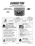
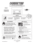
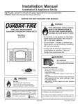
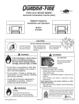
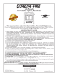
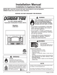
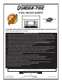
R
5100-I WOOD INSERT
Tested and
Listed by
O-T L
Beaverton
Oregon USA
C
OMNI-Test Laboratories, Inc.
This manual contains instructions for Installation, Operation & Maintenance. Please read this entire
manual before you install and use your new room heater. Failure to follow instructions may result in
property damage, bodily injury, or even death.
IMPORTANT SAFETY NOTES:
1) When installing your insert, particular attention should be paid to fire protection. If this room heater is not properly
installed, a house fire may result. To reduce the risk of fire, follow the installation instructions. Contact local building, fire
officials or authority having jurisdiction about restrictions,installation inspection and permits requirements in your area.
2) CAUTION: Never use gasoline, gasoline-type lantern fuel, kerosene, charcoal lighter fluid, or similar liquids to start or
“freshen up” a fire in this heater. Keep all such liquids well away from the heater while it is in use.
3) During operation, if any part of the insert starts to glow, the insert is in an overfired condition. Close the air controls
completely by pulling them out, until the glowing has stopped. OVERFIRING VOIDS YOUR WARRANTY!
4) Cool ashes should be disposed of carefully, using a metal container.
5) Do not burn wet or green wood. Store wood in a dry location.
6) DO NOT BURN GARBAGE OR FLAMMABLE FLUIDS SUCH AS GASOLINE, NAPHTHA OR ENGINE OIL. Do not
burn treated wood, or wood with salt (driftwood, etc.). Burning materials other than wood (including charcoal) under
adverse conditions may generate carbon monoxide in the home, resulting in illness or possible death.
7) Do not permit creosote or soot to accumulate excessively in the chimney or inside the firebox.
8) Check your chimney system thoroughly when installing into an existing metal or masonry chimney. Seek professional
advice if in doubt about its condition.
9) Do not connect this unit to a chimnney flue already serving another appliance.
10) Comply with all minimum clearances to combustibles as shown in this manual for this appliance.
11) Build fire on brick firebox floor. Do not use grates, andirons or other methods to support fuel.
12) HOT WHILE IN OPERATION! Keep children, pets, clothing and furniture away. Contact can cause skin burns.
13) Do not connect to any air distribution duct or system.
14) RISK OF FIRE! Do not operate with insert door open. Operating with door open could result in overfiring.
15) For further information refer to NFPA 211 (US) or CAN/CSA-B365 (Canada).
16) Do not operate without fully assembling all components.
17) Do not operate with broken glass.
PRIOR TO FIRST FIRE: Remove all labels from glass. Clean plated surfaces with a glass cleanser and soft cloth
to prevent staining from fingerprint oils.
SAVE THESE INSTRUCTIONS
1445 North Highway
Colville, WA 99114
Part 250-1960 Rev B
January 30, 2004
www.quadrafire.com
R
5100-I WOOD INSERT
Hearth & Home Technologies welcomes you to our tradition of excellence! In choosing a Quadra-Fire appliance, you
have our assurance of commitment to quality, durability, and performance.
This commitment begins with our research of the market, including ‘Voice of the Customer’ contacts, ensuring we make
products that will satisfy your needs. Our Research and Development facility then employs the world’s most advanced
technology to achieve the optimum operation of our stoves, inserts and fireplaces. And yet we are old-fashioned when it
comes to craftsmanship. Each unit is meticulously fabricated and gold surfaces are hand-finished for lasting beauty and
enjoyment. Our pledge to quality is completed as each model undergoes a quality control inspection. Additionally, we feel
it is important to offer you several finishing options and accessories to complement your home’s décor, individualize the
use of your appliance, and provide financial options in acquiring a quality hearth appliance. Ask your Quadra-Fire Dealer
for information on these options. From design, to fabrication, to shipping: Our guarantee of quality is more than a word,
it’s Quadra-Fire tradition, and we proudly back this tradition with a Limited Lifetime Warranty.
Prior to installation, we ask you to take a few moments to read this manual. It has been our experience that your
overall enjoyment of your new appliance will be greatly enhanced by becoming familiar with its installation, operation
and maintenance. We wish you and your family many years of enjoyment in the warmth and comfort of your hearth
appliance. Thank you for choosing Quadra-Fire.
With warm regards,
___________________________
Alan Trusler
Senior Vice President
Dealer Channel
___________________________
Dan Henry
Vice President
Research & Development
_________________________
Jason Olmstead
Vice President &
General Manager
Page 2
___________________________
Mike Derosier
Vice President
Quadra-Fire Brand Manager
_________________________
Dave Fiebelkorn
Materials Manager
250-1960 Rev B
January 30, 2004
R
5100-I WOOD INSERT
MODEL NAME
SAFETY & OVERVIEW OF APPLIANCE
Dimensions ----------------------------------------------------- 4
Minimum Clearances to Combustibles ------------------ 5
Location of Serial Number Label-------------------------- 5
Listings ---------------------------------------------------------- 6
Chimney Height & Draft and 2-10-30 Rule ------------- 6
Installation Recommendations ---------------------------- 5
General Installation Procedures -------------------------- 7
Alternate Floor Protection Worksheet ------------------- 7
Chimney Requirements ------------------------------------- 8
Ovalizing Round Stainless Steel Liners ----------------- 8
Quadra-Fire
5100-I WOOD INSERT
Serial Number
Date Purchased
INSTALLATION OPTIONS
Mobile Home --------------------------------------------------- 9
Masonry Fireplace-------------------------------------------- 10
Metal Heat Circulating Masonry--------------------------- 10
Zero Clearance Factory Built Fireplace ----------------- 11
Canadian Masonry & Heat Circulating ------------------ 12
Leveling Bolts ------------------------------------------------- 12
Securing Liner to Chimney Ring -------------------------- 12
Dealership Where Purchased
Dealer Phone
PARTS & ACCESSORY INSTALLATION
Outside Air Installation -------------------------------------- 13
Blower Cord Installation & Snap Disc Operation------ 13
Blower Replacement ----------------------------------------- 14
Fan Speed Control Adjustment---------------------------- 14
Fan Wiring Diagram ------------------------------------------ 14
Panel Sets and Trim Sets ----------------------------------- 15
Zero Clearance Adjustable Trim Support --------------- 16
Additional Information:
OPERATION OVERVIEW
Wood Selection & Storing ---------------------------------- 17
Overfiring ------------------------------------------------------- 17
Building A Fire------------------------------------------------- 17
Burn Rates & Opacity --------------------------------------- 18
Fan Operation Instructions --------------------------------- 18
Ash Removal -------------------------------------------------- 18
Air Quality ------------------------------------------------------ 19
Air Controls, Primary & Start-up -------------------------- 19
AFTER COMPLETING YOUR WARRANTY CARD, ATTACH
YOUR SALES RECEIPT AND WARRANTY STUB HERE
FOR FUTURE REFERENCE.
MAINTENANCE
Plated Surfaces ----------------------------------------------- 20
Glass Cleaning & Replacement -------------------------- 20
Creosote Formation & Removal -------------------------- 20
Chimney -------------------------------------------------------- 20
Brick Replacement ------------------------------------------- 21
Baffle Removal & Replacement--------------------------- 21
PARTS & ACCESSORIES LIST ------------------------- 22
WARRANTY POLICY--------------------------------------- 23
January 30, 2004
250-1960 Rev B
Page 3
R
5100-I WOOD INSERT
DIMENSIONS
TOP VIEW
34-3/16"
(919mm)
25-5/8"
(651mm)
SIDE VIEW
26-3/4"
(679mm)
CL
17-7/8"
(454mm)
12-7/8"
(327mm)
9-1/8"
(232mm)
12.0"
(305mm)
39-1/8"
(994mm)
22-1/4"
(565mm)
21-1/8"
(537mm)
10-1/2"
(267mm)
29-5/8"
(752mm)
FRONT VIEW
A
39-1/8"
(994mm)
Page 4
Panel
Size
STD
47”
30-1/2”
Large
51-1/4”
34-1/4”
A
B
B
250-1960 Rev B
January 30, 2004
R
5100-I WOOD INSERT
CLEARANCES TO COMBUSTIBLES
United States and Canada
In Canada a full length 6” (152mm) S635 flue liner required
as per ULC S628.
Mantel
SideWall
B
NOTE: When installling into a masonry fireplace, the fireplace must be built to UBC Chapter 37 standards. Do not
remove brick or mortar from masonry fireplace to accomodate insert. The permanent metal warning plate provided
must be attached to the back of the fireplace stating the fireplace may have been altered to accomodate the insert and
must be returned to original condition for use as a conventional fireplace.
Fascia or Trim
C
A
Insert
D
E
F
Hearth Extension
A
B
C
D
INSTALLATION: Masonry, Heat Circulating and *Zero Clearance
12" (305)
40" (1016)
35" (889)
E
F
7" (178)
16" (406)
8"(200)
18" (457) Canada
7" (178)
16" (406)
8"(200)
18" (457) Canada
7" (178)
16" (406)
8"(200)
18" (457) Canada
With 5" Mantel Deflector, Part No. 831-1520
12" (305)
29" (737)
20" (889)
With 8" Mantel Deflector, Part No. 831-1530
12" (305)
23" (585)
16" (406)
*Zero Clearance in USA Only.
THERMAL PROTECTION USA & CANADA
Thermal protection must be 1 inch (25mm) minimum thickness (“k” value = 0.84) or equivalent material.
See Alternate Floor Protection Work Sheet on page 7.
SERIAL NUMBER LABEL LOCATION:
ON RIGHT SIDE OF INSERT AS YOU FACE THE APPLIANCE
January 30, 2004
250-1960 Rev B
Page 5
R
5100-I WOOD INSERT
LISTINGS
CHIMNEY HEIGHT/DRAFT (CONT’D)
These installation instructions describe the installation and operation of the Quadra-Fire 5100-I Wood Insert. This insert meets the
U.S. Environmental Protection Agency’s 1990 particulate emission
standards. The 5100-I is listed by OMNI-Test Laboratories, Inc.
to UL Safety Standard 1482, and ULC S628, and (UM) 84-HUD.
The 5100-I is approved for mobile home installations when not
installed in a sleeping room and when an outside combustion air
inlet is provided. The structural integrity of the mobile home floor,
ceiling, and walls must be maintained. The insert must be properly
grounded to the frame of the mobile home.
AVOID FIRE: To ensure that insulation or any other combustible
material does not contact the chimney, a chimney inside the house
must have at least 2 inches (51mm) of air space clearance around
the chimney. A chimney outside the house must have at least 1
inch (25mm) clearance to the combustible structure. Noncombustible fire stops must be installed at the spaces where the chimney
passes through floors and/or ceilings. Refer to Figures 8A & 8B
on page 8. Canadian installations require a full reline of the
chimney
Check with your local building code agency before you begin your
installation to ensure compliance with local codes, including the
need for permits and follow-up inspections. Be sure local building
codes do not supersede UL specifications and always obtain a
building permit so that insurance protection benefits cannot be
unexpectedly cancelled. If any assistance is required during
installation, please contact your local dealer.
NOTE: Clearances may only be reduced by means approved by
the regulatory authority having jurisdiction.
WE RECOMMEND that a qualified building inspector and your
insurance company representative review your plans before
installation.
INSTALLATION RECOMMENDATIONS
CHIMNEY HEIGHT/DRAFT
To be sure that your Quadra-Fire insert burns properly, the chimney
draft (static pressure) should be approximately -0.10” water column
(W.C.) during a high burn and -0.04” W.C. during a low burn,
measured 6” (152mm) above the top of the insert after one hour of
operation at each burn setting.
NOTE: These are guidelines only, and may vary somewhat for
individual installations.
Your Quadra-Fire insert was designed for and tested on a 6”
(152mm) chimney, 12 ft-14 ft (360-420cm) high, measured from
the base of the insert. The further your stack height or diameter
varies from this configuration, the possibility of performance
problems increases. In addition, exterior conditions such as roof
line, surrounding trees, prevailing winds and nearby hills can
influence insert’s performance.
A masonry chimney or a listed factory-built UL103 HT Class “A”
chimney must be the required height above the roof and any other
nearby obstructions. The chimney must be at least 3 ft (91cm)
higher than the highest point where it passes through the roof and at
least 2 ft (61cm) higher than the highest part of the roof or structure
that is within 10 ft (305cm) of the chimney, measured horizontally.
See 2-10-3 Rule (Figure 6A). These are safety requirements
and are not meant to assure proper flue draft.
The Quadra-Fire 5100-I Insert has met and surpassed the most
stringent emissions standards in the United States. The sophistication of the interior firebox design requires that a proper draft be supplied by the chimney, therefore adherence to the following factors
will enable your insert to operate at its optimum capability.
REQUIRED: A minimum starter pipe reaching to the base of the
existing code approved masonry chimney and an airtight face seal,
but a full chimney liner for factory-built fireplaces is recommended
for USA and is required in Canada.
BETTER: Direct connection to the first flue liner in accordance with
the requirements of the NFPA 211.
BEST: A complete relining of the chimney system with a 6 inch
(152mm) diameter listed, stainless liner. Required for factory-built
fireplace installations in Canada, recommended in USA. The sections
must be attached to the insert and to each other with the crimped
(male) end pointing toward the insert. See Figure 6B. All joints,
including the connection at the flue collar, should be secured with
three sheet metal screws. Make sure to follow the minimum clearances to combustibles as set out on Page 5 of the manual.
LINER CONNECTOR
2-10-3 RULE
3 ft Min
(91cm)
2 ft Min (61cm)
FLUE
GAS
DIRECTION
TOWARDS
STOVE
10 ft Min
(305cm)
Figure 6B
Figure 6A
Page 6
250-1960 Rev B
January 30, 2004
R
5100-I WOOD INSERT
GENERAL INSTALLATION PROCEDURE
•
•
•
•
•
•
•
•
•
•
•
DO NOT CONNECT THIS UNIT TO A CHIMNEY FLUE SERVING ANOTHER APPLIANCE.
Install liner, if required, for your chosen installation.
Attach metal warning plate to the back of the fireplace with screws or nails.
Set appliance on the hearth (See Hearth Requirements page 5 and Support Kit information on page 16.
Complete the vent connection required for your installation type.
Relocate plate for Outside Air (Required for Mobile Home Installation). See page 13. Attach Panel Set to insert and
install Trim Set. See page 15.
Position unit into fireplace leaving width enough for fiberglass batting to be inserted around face seal.
Work unit securely into the fireplace using sheet metal shims if leveling bolts are needed. See Figure 12B on page 12.
Remove all labels from glass prior to building first fire.
Ensure that plated surfaces are cleaned prior to building first fire. See page 20.
Read Operation Instructions found on pages 18 and 19.
IF INSTALLING THIS MODEL TO A MASONRY CHIMNEY, ALWAYS BE SURE THE CHIMNEY IS IN GOOD CONDITION AND
THAT IT MEETS THE MINIMUM STANDARDS OF THE NATIONAL FIRE PROTECTION ASSOCIATION (NFPA) STANDARD 211.
A FACTORY BUILT CHIMNEY MUST BE 6 INCH (152mm) UL 103 HT AND ULC S629.
THIS APPLIANCE IS MADE WITH A 6 INCH (152mm) DIAMETER CHIMNEY CONNECTOR AS THE FLUE COLLAR ON THE
UNIT. CHANGING THE DIAMETER OF THE CHIMNEY CAN AFFECT DRAFT AND CAUSE POOR PERFORMANCE. IT IS NOT
RECOMMENDED TO USE OFFSETS OR ELBOWS AT ALTITUDES ABOVE 4000 FEET ABOVE SEA LEVEL OR WHEN THERE
ARE OTHER FACTORS THAT AFFECT FLUE DRAFT.T SEE PAGE 5.
CAUTION: THIS APPLIANCE IS HOT WHILE IN OPERATION AND MAY REMAIN SO UP TO 40 MINUTES AFTER THERE
IS NO FUEL IN THE FIREBOX. IF THIS APPLIANCE IS IN A HIGH TRAFFIC AREA OR CHILDREN MAY BE NEAR, IT IS
RECOMMENDED THAT YOU PURCHASE A DECORATIVE BARRIOR TO GO IN FRONT OF THE APPLIANCE.
ALTERNATE FLOOR PROTECTION WORKSHEET
How to determine if alternate floor protection materials are acceptable:
All floor protection must be non-combustible (i.e., metals, brick, stone, mineral fiber boards, etc.). Any organic materials (i.e., plastics, wood paper
products, etc.) are combustible and must not be used. The floor protection specified includes some form of thermal designation such as R-value
(thermal resistance) or k-factor (thermal conductivity).
PROCEDURE:
1. Convert specification to R-value:
R-value given - no conversion needed.
K-factor is given with a required thickness (T) in inches:
1
xT
k
k-factor is given with a required thickness (T) in inches: R =
1
R = K x 12 x T
r-factor is given with a required thickness (T) in inches: R =
2. Determine the R-value of the proposed alternate floor protector.
i. Use the formula in step (1) to convert values not expressed as “R”.
ii. For multiple layers, add R-values of each layer to determine overall R-value.
3. If the overall R-value of the system is greater than the R-value of the specified floor protector, the alternate is acceptable.
EXAMPLE: The specified floor protector should be 3/4 inch thick material with a k-factor of 0.84. The proposed alternate is 4” brick with an r-factor
of 0.2 over 1/8” mineral board with a k-factor of 0.29.
4" brick of r = 0.2, therefore:
1
x 0.75 = 0.893
.84
1/8" mineral board of k = 0.29, therefore:
R
R
Step (a): Use formula above to convert specification to R-value.
Step (b): Calculate R of proposed system.
brick
R=
1
xT
k
= 0.2 x 4 = 0.431
R
total
=R
brick
+R
=
mineral board
mineral board
=
1
x 0.125 = 0.431
0.29
= 0.8 + 0.431 = 1.231
Step (c): Compare proposed system Rtotal of 1.231 to specified R of 0.893. Since proposed system Rtotal is greater than required, the system
is acceptable.
2
R=
January 30, 2004
(ft )(hr)(oF)
Btu
= K x 12
k = Btu(in)
2
ft (hr)(oF)
K=
Btu(ft)
2
ft (hr)(oF)
250-1960 Rev B
2
o
r = (ft )(hr)( F)= 1
k
(Btu)(in)
Page 7
R
5100-I WOOD INSERT
CHIMNEY REQUIREMENTS
A chimney must be the required height above the roof
or other obstruction for safety and for proper draft operation. The requirement is that the chimney must be at
least 3 feet (91cm) higher than the highest point where
it passes through the roof, and at least 2 feet (61cm)
higher than the highest part of the roof or structure that
is within10 feet (305cm) of the chimney, measured horizontally. Refer to Figure 8C.
Figure 8A
OVALIZING ROUND STAINLESS STEEL
LINERS
Ovalizing round stainless steel liners to acommodate
the liner passing through the damper region of a fireplace is an allowable and acceptable practice.
Ensure that the ovalization is minimized to the extent
required to fit through the damper.
Firestopping
Non-Combustible
Firestopping
Material
Figure 8C
10 ft
(305cm)
Floor
2 inch
(51mm)
At least 2 ft
(61cm)
At least 3 ft
(91cm)
Ceiling
Caulk
Floor
(second Story)
CHIMNEY HEIGHT
Minimum 1 inch (25mm)
clearance from exterior
chimney to sheathing
Figure 8D
Figure 8B
Minimum 2 inch (51mm) clearance
from combustible material
and insulation
CHIMNEY TOP VIEW
1/2" (12.7mm) airspace
ceiling
FLUE
Non-combustible
fire stopping material
5/8" (16mm)
Fireclay Flue
Liner
Chimney Wall
4" (102mm)
Nominal
Foundation
Page 8
250-1960 Rev B
January 30, 2004
R
5100-I WOOD INSERT
INSTALLATIONS INTO ZERO CLEARANCE FIREPLACES IN MOBILE HOMES
(IN USA ONLY)
1.
An outside air inlet must be provided for combustion and must
remain clear of leaves, debris, ice and/or snow. It must be
unrestricted while unit is in use to prevent room air starvation
which can cause smoke spillage and an inability to maintain a
fire. Smoke spillage can also set off smoke alarms.
2.
Unit must be secured to the mobile home structure. Remove
bolts from each side of insert and use plumbers tape to secure
to structure (a washer may be required). Reinstall bolts.
3.
Unit must be grounded with #8 solid copper grounding wire or
equivalent and terminated at each end with N.E.C. approved
grounding device.
Spark Arestor Cap
Storm Collar
Roof Flashing
Joist Shield/Firestop
Double Wall
Connector Pipe
4.
The factory-built fireplace must meet (UM)84-HUD
requirements for outside combustion air supply to the firepalce
fire chamber and the chimney must be listed to UL103-HT
or a listed UL-1777 full length 6 inch (152mm) diameter liner
must be used. It must be equipped with a spark arrestor cap
and the outside air must be installed on the insert. (See Figure 9A and complete installation instructions
of page 13.)
5.
Refer to page 5 of this manual or the Serial label located on the right side of the insert for clearances to
combustibles.
6.
Floor protections requirements on page 5 must be followed precisely.
7.
Use silicone to create an effective vapor barrier at the location were the chimney or other component penetrates
to the exterior of the structure.
8.
Follow the chimney and chimney connector manufacturer’s instructions when installing the flue system for use
in a mobile home.
NOTE: Offsets from the vertical, not exceeding 45°, are allowed per Section 905(a) of the Uniform Mechanical Code
(UMC). Offsets greater than 45° are considered horizontal and are also allowed, providing the horizontal run does
not exceed 75% of the vertical height of the vent. Construction, clearance and termination must be in compliance
with the UMC Table 9C. This installation must also complies with NFPA 211.
NOTE: Top sections of chimney must be removable to allow maximum clearance of 13.5’ (405cm) from ground level
for transportation purposes.
9.
Burn wood only. Other types of fuels may generate poisonous gases (e.g., carbon monoxide).
Cover from rear of
stove is secured
to front of stove
See complete
instructions on
page 13
CAUTION: THE STRUCTURAL INTEGRITY OF THE MOBILE
HOME FLOOR, WALL AND CEILING/ROOF MUST BE
MAINTAINED. (i.e., DO NOT CUT THROUGH FLOOR JOIST,
WALL STUD, CEILING TRUSS, ETC.)
WARNING: DO NOT INSTALL IN SLEEPING ROOM.
January 30, 2004
Remove 2 Spring Handles
Figure 9A - Installing Outside Air
WARNING: NEVER DRAW COMBUSTION AIR FROM A WALL,
FLOOR OR CEILING CAVITY OR FROM ANY ENCLOSED
SPACE SUCH AS AN ATTIC OR GARAGE.
250-1960 Rev B
Page 9
R
5100-I WOOD INSERT
INSTALLATION OPTIONS
Refer to: Clearances to Combustibles on page 5, Canadian Installation requirements on page 12,
Hearth Requirements on page 5 and Zero Clearance Adjustable Support Kit on page 16.
MASONRY FIREPLACE
USING DIRECT-CONNECT METHOD
Masonry Chimney
Flue Tile
The Quadra-Fire 5100-I Insert conforms with the UL Standard for Safety 1482 and ULC S628 (Canada) in all respects,
and is approved to UL & ULC safety standards for installation and use within a fireplace with a masonry chimney in
accordance with NFPA No. 211, with or without a direct flue
collar connection. A starter pipe is required to reach to the
bottom of the existing flue.
Full Listed
Liner Option
Mantel
Direct Connect
Seal Option
Air-tight Face Seal
Damper Area
Minimum Starter
Pipe Option
1. Secure the fireplace damper in the open position. If this
cannot be accomplished, it will be necessary to remove the
damper.
2. Seal either the damper area around the chimney liner
with a high temperature sealant or the fireplace front with
fiberglass batting.
3. The chimney should be examined for cracks, loose mortar,
and other signs of deterioration and blockage. The insert
should not be installed until it is determined that the chimney is safe for use. Since an oversized flue contributes to
the accumulation of creosote, the size of the flue should be
checked to determine that it is not too large for the insert.
The chimney should also be checked to ensure it meets the
minimum standard of the National Fire Protection Association (NFPA) Standard 211. The following bullets list the more
critical requirements for a properly constructed chimney:
• The masonry wall of the chimney, if brick or modular
block, must be a minimum of 4 inches (102mm) nominal
thickness. A chimney of rubble stone must be at least 12
inches (305mm) thick
SEAL DAMPER AREA OR FACE SEAL
Figure 10A - Installation Into Masonry Fireplace
METAL HEAT CIRCULATING MASONRY
The Quadra-Fire 5100-I Insert conforms with the safety
standard UL-1482 and ULC S628 (Canada) in all respects
and is approved to UL & ULC safety standards for installation and use within a fireplace with masonry chimney, in
accordance with NFPA No. 211, with or without a direct flue
collar connection. A starter pipe is required into existing
chimney.
• The chimney must have a fire clay flue liner (or equivalent) with a minimum thickness of 5/8” (16mm) and must be
installed with refractory mortar. An equivalent liner must be
a listed chimney liner system or other approved material.
Mantel
Listed Liner
• A chimney inside the house must have at least 2 inches
(51mm) of clearance to the combustible structure. A chimney outside the house must have at least 1 inch (25mm)
clearance to the combustible structure. Non-combustible fire
stops must be installed at the spaces where the chimney
passes through floors and/or ceiling (See Figure 8A and 8B
on page 8).
SEAL DAMPER AREA OR FACE SEAL
NOTE: In Canada, a full reline is required.
Page 10
Figure 10B - Installation Into Metal Heat Circulating
Showing Use Of Starter Pipe
250-1960 Rev B
January 30, 2004
R
5100-I WOOD INSERT
FACTORY BUILT ZERO CLEARANCE FIREPLACE
(USA INSTALLATONS ONLY)
The Quadra-Fire 5100-I Insert is listed to UL Standards for Safety 127 and approved for installation and use in factory built
zero clearance fireplaces conforming to the following specifications:
Minimum Width of cavity opening:
36”
915mm
Minimum Height:
24”
610mm
Minimum Depth from front to rear:
19”
483mm
The following modifications of factory built fireplaces are permissible: 1) removal of damper; 2) removal of smoke shelf
or baffle; 3) removal of ember catches; 4) removal of fire grate; 5) removal of viewing screen/curtain; and, 6) removal of
doors.
NOTE: Installation into fireplaces without a permit will void the listing.
The factory built chimney must be listed per UL 127 and meet the type HT requirements of UL 103. Factory built fireplace
chimneys tested to UL 127-1998, may be at the fireplace manufacturer’s option, tested to the same criteria as UL 103 HT
requirements. If the chimney is not listed as meeting HT requirements, or if the factory built fireplace was tested prior to
1998, a full height listed chimney liner must be installed from the appliance flue collar to the chimney top. The liner must
meet type HT requirements (2100ºF) per UL 1777. The liner must be securely attached to the insert flue collar and the
chimney top. To prevent room air passage to the chimney cavity of the fireplace, seal either the damper area around the
chimney liner with high temperature sealant or the fireplace front with fiberglass batting.
The fireplace must not be altered, except that the damper may be removed to accommodate a direct-connect starter pipe
or chimney liner, and external trim pieces which do not affect the operation of the fireplace may be removed providing
they can be stored on or within the fireplace for reassembly if the insert is removed. The permanent metal warning label
provided must be attached to the back of the fireplace, with screws or nails, stating that the fireplace may have been
altered to accommodate the insert, and must be returned to
original condition for use as a conventional fireplace.
If the hearth extension is lower than the fireplace opening,
the portion of the insert extending onto the hearth must be
supported. Manufacturer designed adjustable support kit
can be ordered from your dealer. (See page 16).
Final approval of this installation type is contingent upon
the authority having jurisdiction.
Mantel
Listed Liner
SEAL DAMPER AREA OR FACE SEAL
Figure 11A - Installation Into A Factory Built
Zero Clearance Fireplace
January 30, 2004
250-1960 Rev B
Page 11
R
5100-I WOOD INSERT
INSTALLATION IN CANADA
MASONRY and HEAT-CIRCULATING
(INSTALLATIONS INTO FACTORY-BUILT FIREPLACES ARE PROHIBITED IN CANADA)
Whether installed in a masonry or heat-circulating fireplace, this fireplace insert must be installed with a continuous chimney liner of 6” (152mm) diameter extending from the fireplace insert to the top of the chimney. The chimney liner must
conform to the Class 3 requirements of CAN/ULC-S635, Standard for Lining Systems for Existing Masonry or Factory-Built
Chimneys and Vents, or CAN/ULC-S640, Standard for Lining Systems for New Masonry Chimneys.
• Do not remove bricks or mortar from fireplace to accommodate insert.
• The face of the fireplace must be sealed to prevent room air passage into the chimney cavity.
• The permanent metal warning label provided must be affixed to the back of the fireplace with screws or nails
to the fireplace, in a location readily visible should the fireplace insert by removed, stating that the fireplace may
have been altered to accommodate the insert, and must be returned to original condition for use as a conventional
fireplace.
USE OF LEVELING BOLTS
Two leveling bolts, 3/8” x 4” are shipped inside the component pack found inside the firebox.
NOTE: Not all installations will require the use of the leveling bolts. If the leveling bolts are necessary, you will also need
sheetmetal guides placed under the leveling bolts to slide insert into position.
1. Remove the bolts from the component pack.
2. Locate the weld nuts welded to each side of the insert bottom and insert the bolts.
3. Position insert on hearth with rear of insert extending into fireplace opening.
4. Extend leveling bolts downward to level insert.
SECURING LINER TO CHIMNEY RING
There are two options to secure the liner to the chimney ring: (See Figure 12A).
Option One: If there is enough room on the top of the
insert to work, hand bend the two tabs upward 90°.
Secure the liner with the supplied hex head bolts 1/420-3/4.
Option Two: Remove the manifold tubes, fiberboard
baffle and ceramic blanket. From inside the firebox,
pull liner down through the chimney ring below the
outer skin. There are two pre-drilled holes in the chimney ring 180° apart. Secure the liner with the supplied
hex head bolts 1/4-20-3/4.
2 pre-drilled holes on
chimney ring under outer skin
(access through firebox)
Attach liner with 2 tab
s
NOTE: Tabs are shipped from factory in a flat position.
Bend upwards 90 degrees.
Figure 12A
Page 12
250-1960 Rev B
January 30, 2004
R
5100-I WOOD INSERT
OUTSIDE AIR INSTALLATION
Cover from rear
of stove is
secured to front
of stove
Remove 2 Spring Handles
Figure 13A
Tools Needed: Phillips Head Screwdriver
1)
Remove cover from rear of stove by removing screws.
2)
Remove the 2 Air Control spring handles.
3)
Remove the lower grill by removing 2 screws in the center of the grill.
4)
Unplug the snap disc by-pass switch and speed control from the wiring harness for easier access to blower.
(Located on right hand side of stove as you face the unit).
5)
Mount the cover you removed from the back to the front to block room air from entering through the front lower grill.
6) Re-connect snap disc & speed control to wiring harness and replace screws in blower frame.
7)
Reinstall lower grill, replace screws & spring handles.
8)
Push insert back into the fireplace.
9)
Plug blower cord back into outlet.
NOTE: The 5100-I requires replacement of combustion air. If your home is fairly air-tight, it is receommend that
you install outside air. If you are installing into a Mobile Home, outside air is required. See page 9.
BLOWER OPERATION
The 5100-I is equipped with a 110°thermally operated snap disc which will automatically turn on the blower when the insert
reaches this temperature. The snap disc is located at the center of the insert, under the lower grille. There is a manual
override switch on the right side of the insert. The blower can be controlled manually by switching this switch to ON and
operating the blower with the speed control. If the blower does not come on automatically when the stove reaches a sufficient temperature, the snap disc might be bad and should be replaced.
BLOWER CORD LOCATION
The 5100-I Insert comes standard with 2 blowers, installed at the factory with blower cord on right side of insert (as you face
the unit). The blower cord can also be installed on the left side. Disconnect the cord from right side and reinstall on the left
side. ROUTE WIRES BEHIND THE BLOWER. Do not route cord under or in front of appliance.
January 30, 2004
250-1960 Rev B
Page 13
R
5100-I WOOD INSERT
BLOWER REPLACEMENT INSTRUCTIONS
Part 832-1991 for Serial Numbers 131586 and below
Part 832-3190 for Serial Numbers 131587 and above
TOOLS NEEDED: #2 PHILLIPS SCREWDRIVER
1)
2)
3)
4)
Unplug blower cord from outlet.
Pull insert out from the fireplace.
Remove the 2 Air Control spring handles.
Remove the lower grill by removing 2 screws in the center of
the grill.
5) Unplug the snap disc by-pass switch and speed control from
the wiring harness for easier access to blower. (Located on
right hand side of stove as you face the unit).
6) Remove screws from blower frame on side of insert.
7) Blower will then slide out through side of insert.
8) Install new blower in same fashion.
9) Re-connect snap disc & speed control to wiring harness and
replace screws in blower frame.
10) Re-install lower grill, replace screws & spring handles.
11) Push insert back into the fireplace.
12) Plug blower cord back into outlet.
Remove 2 Spring Handles
Figure 14A
FAN SPEED CONTROL ADJUSTMENT, IF NECESSARY*
*The fan Speed Control for this unit is adjusted at the factory, and normally does not require further
adjustment.
NOTE: When the speed control is turned clockwise, it will click on to high speed. Continue to turn the speed control
clockwise to decrease the speed. At full clockwise, the blower should blow gently, but should not stop.
1. With the unit plugged in, turn the Speed Control Knob to slow. (Full clockwise.)
2. Use a small screwdriver to adjust the fan speed by turning the adjustment mechanism through the hole on the
side of the Speed Control.
3. Adjust the speed so the fan runs slowly but does not stop. Turn clockwise to slow the fan and counterclockwise
to increase the speed.
Small Red Female
Small Red Female
LEFT FAN
Small Red Female
Small Red Female
RIGHT FAN
Large Blue Male
POWER IN
WIRING DIAGRAM
Figure 14B
Large Red Female
Large Blue Female
Large Blue Female
Large Blue Male
SNAP DISC
SPEED
CONTROL
Large Red Female
Large Blue Male
AUX POWER
LEFT
Large Blue Female
Large Red Female
SNAP DISC
BY-PASS SWITCH
Large Red Female
Page 14
250-1960 Rev B
January 30, 2004
R
5100-I WOOD INSERT
PANEL and TRIM SET INSTALLATION
STANDARD Size: 30-1/2” h x 47”w
LARGE Size: 34-1/4” h x 51-1/4”w
831-1452, Gold Trim
SP-51S-NL, Nickel Trim
831-1461, Gold Trim
SP-51l-NL, Nickel Trim
Kit Includes: (2) Side Panels, left & right; (1) Panel Top & Fastener package; (2) Side Trim, left & right; (1) Trim Top & Fastener package.
Tools Needed: Powered Phillips head screw driver and a long handled Phillips screw driver .
Assembling Trim
Attaching Panels to the Insert
1. Loosely install the 2 side panels, do not tighten, using the
cage nuts already attached to the stove. (Note: The sides are
not interchangeable).
2. Put top panel in place pushing straight back and then to the
right to lock onto top of side panels. Attach the top panel
to the sides using the screw already installed at the top of
side panels and the panel brackets included in the fasteners
package.
1. Place protective covering on surface to be used to assemble
the trim pieces. Lay the trim face down.
2. Attach the 2 side trim pieces to the top trim at each corner
using the “L” bracket included in fasteners package. Slide
assembled trim over panel set. See Figure 15C.
3. Tighten side panels to the stove using a long handle screw
driver. See Figure 15B.
View of "L" Bracket
installed
Panel brackets
Do not tighten sides until
top is locked into place
Figure 15A
Figure 15C
Back view of top
and side panel
assembled
Figure 13B
January 30, 2004
250-1960 Rev B
Page 15
R
5100-I WOOD INSERT
ZERO CLEARANCE ADJUSTABLE TRIM SUPPORT, 2” to 10”
Part No. ADJSPT-12, size 12” x 50”
Included in Kit: (1) Trim Top, (1) Trim Front, (2) Trim Sides, Double-Sided Tape (already installed)
Tools Needed: Phillips Head Screwdriver, Sheet Metal Shears, Measuring Tape, Gloves
EXPLODED VIEW OF SCISSORS
1. The 10 screws on each set of scissors will already be
loose when shipped. See Figure 16A.
2.
Expand scissors to desired height. Tighten screws
to hold in place using Phillips Head screwdriver. See
Figure 16B.
3. Measure front and side trims to required height to cover
scissors and mark pieces for cutting. Cut excess material from top of trim’s edge, not bottom. This edge will be
sharp; wear gloves to prevent injury to your hands. See
Figure 16B.
4. Using sheet metal shears, cut trim along the marked
edge. The cut edge fits under lip of top trim, so it allows
for some variance in your straight edge.
5. The double-sided tape that holds front and side trims
to scissors has a particularly powerful bonding adhesive. Adjustments are extremely difficult once trim has
adhered to tape. Do a dry run first without removing
paper from tape.
6. Place cut edge of trim under top lip and into position on
scissors. Place side pieces on first and then front piece.
The front piece overlaps side pieces. NOTE: The trim in
the Flush Mount Kit is one piece.
SCREWS ARE CIRCLED
DOUBLE-SIDED TAPE
Figure 16A
DOUBLE-SIDED TAPE
EXPAND SCISSORS TO DESIRED
INSTALL FRONT TRIM LAST.
CORNERS OVERLAP SIDE
TRIM PIECES
CUT TOP EDGE OF TRIM,
NOT BOTTOM EDGE
Figure 16B
7. Once you are satisfied with the positioning, remove trim
and set aside.
8. Remove the paper from double-sided tape that is to
accept trim side. Align side and then press hard against
tape to secure side piece. Repeat for other side. Install
front trim piece last.
NOTE: 3/8” ( 9.5mm) thick tile or like material can be cut to
size and fit under lip of top trim edge for a decorative touch.
See Figure 16C.
Decorative tile may
be installed
Figure 16C
Figure 16D
Page 16
250-1960 Rev B
January 30, 2004
R
5100-I WOOD INSERT
OPERATION
WOOD SELECTION AND STORAGE
Burn only dry seasoned wood. Dry, well-seasoned wood will not only minimize the chance of creosote formation but will give you the
most efficient heat output. Even dry wood contains at least 15% moisture by weight and should be burned hot enough to keep the
chimney hot enough to maintain particulate (smoke) burning. Burning unseasoned wood of any variety defeats the stoves’ efficiency.
Dead wood lying on the forest floor should be considered wet, and requires full seasoning time. Standing wood can be considered to be
about two-thirds seasoned. Wood is dry enough to burn if the ends of the logs have cracks radiating in all directions from the center. If
your wood sizzles in the fire, even though the surface is dry, it may not be fully cured.
Drying time can be reduced by splitting wood prior to storage. Since the majority of drying occurs through the cut ends rather than the
sides, stack the wood so both ends of each piece are exposed to air. Store wood under cover, such as in a shed, or covered with a tarp,
plastic, tarpaper, sheets of scrap plywood, etc.
OVERFIRING
Do not overfire. Overfiring can result in crazing, an effect causing a white, non-removable film to be deposited on the inside of the glass.
Using flammable liquids or too much wood, or burning trash in the insert, may result in overfiring. If the chimney connector or insert
glows red, or worse, white, the insert is overfired. This condition may ignite creosote in the chimney, possibly causing a house fire. If any
part of the insert starts to glow, you are in an overfire situation. If you overfire, immediately close the insert dampers and door, if open,
to reduce the air supply to the fire. Overfiring your insert voids your warranty.
BUILDING A FIRE
NOTE: Remove all labels from glass front prior to lighting the first fire.
Before lighting your first fire in the insert, make certain that the baffle is correctly positioned. It should be resting against the rear support.
Also refer to care and cleaning of gold/nickel plated surfaces on cover page before lighting your first fire.
CAUTION: Never use gasoline, gasoline-type lantern fuel, kerosene, charcoal lighter fluid, or similar liquids to start or “freshen
up” a fire in this heater. Keep all such liquids well away from the heater while it is in use.
There are many ways to build a fire. The basic principle is to light easily-ignitable tinder or paper, which ignites the fast burning kindling,
which in turn ignites the slow-burning firewood. Here is one method that works well:
1.
Place several wads of crushed paper on the firebox floor. Heating flue with slightly crumpled newspaper before adding
kindling keeps smoke to a minimum.
2.
Place several wads of crushed paper on the firebox floor.
3.
Open Start-Up Air Control (right side) and Primary Air Control (under ashcatcher) fully. See Figure 19A on page 19.
4.
Ensure that no matches or other combustibles are in the immediate area of the insert, that the room is adequately ventilated,
and the flue is unobstructed.
5.
Light the paper in the insert. NEVER light or rekindle insert with kerosene, gasoline, or charcoal lighter fluid; the results
can be fatal.
6.
Once the kindling is burning quickly, add several full-length logs 3” (76mm) or 4” (102mm) in diameter. Be careful not to
smother the fire. Stack the pieces of wood carefully: near enough to keep each other hot, but far enough away from each
other to allow adequate air flow between them.
7.
When ready to reload the insert, add more logs. Large logs burn slowly, holding a fire longer. Small logs burn fast and
hot, giving quick heat.
8. Adjust the Start-Up Air Control and Primary Air Control, maintaining flames above the fuel. The more you close down the Primary
Control, the lower and slower the fire will burn. The more you open the Primary Control the more heat will be produced. The Start-Up
Air Control (right side) is only used for the first 5 to 15 minutes.
As long as there are hot coals, repeating steps 7 and 8 will maintain a continuous fire.
NOTE: The special high temperature finish paint applied to the insert will cure as your insert heats. You will notice an odor
and perhaps see some vapor rise from the insert surface, this is normal. We recommend that you open a window until the odor
dissipates and the paint is cured.
January 30, 2004
250-1960 Rev B
Page 17
R
5100-I WOOD INSERT
OPERATING TIPS
For maximum operating efficiency with the lowest emissions, follow these operating procedures:
1.
Regardless of desired heat output, when loading stove, burn your Quadra-Fire with both air controls wide open for a minimum
of 5 to 15 minutes.
2.
Regulate burn rate (heat output) by using the Primary Control (under ashcather). The Start-Up Air Control (right side) is mainly
for initial start-up and reloading.
3.
Heat output settings: Follow burn rate instructions listed below.
4. Burn only dry, well-seasoned wood.
BTU / Hr
Below 10,000
10,000 - 15,000
15,000 - 30,000
Maximum Heat
Start-Up Air Control
Closed after 5 to 15 minutes
Closed after 5 to 15 minutes
Closed after 5 to 15 minutes
Closed after 5 to 15 minutes
Primary Control
Pull to Stop
3/4” - 1” open
1” - 2-1/2” open
Fully open
These are approximate settings, and will vary with type of wood or chimney draft.
WARNING: Do not operate with Start-Up
Air Control in the open position in excess
of 15 minutes! Risk of extreme temperatures! Prolonged operation of this
stove with the Start-Up Air Control in the
open position may cause the combustible materials around the stove to exceed
safe temperature limits.
BURN RATES
STARTING FIRE: Open both controls (push in) completely. After a wood load has been burning on high for 5 to 15 minutes or longer for
very large pieces, close the Start-Up Air Control (right side) by pulling it out.
HIGH: Leave the Primary Air Control fully open (under ashcatcher). It is especially important to fully open both controls when reloading
the insert as failure to do so could result in excessive emissions, also referred to as ‘opacity’.
After a wood load has been burning on high for 5 to 15 minutes on High to achieve the following burn rates set the
controls as listed below:
MEDIUM HIGH: Close the Primary Air Control to 1” to 2-1/2” (25mm to 64mm) open. Start-Up Air is closed.
MEDIUM: Close the Primary Air Control to 3/4” to 1” (19mm to 25mm) open. Start-Up Air is closed.
LOW: Gradually close down the Primary Air Control by pulling out making sure to maintain flames in the insert. (Start-Up Air is closed).
It is very important to maintain flames in your insert during the first few hours of a low burn to avoid excessive air pollution.
OPACITY
Opacity is the measure of how clean your insert is burning and is measured in percentages. An opacity of 100% in the smoke column
from a chimney will totally obscure an object. Whereas 0% opacity means that no smoke column can be seen. A periodic check of the
opacity emitted from your chimney will enable you to burn your insert as smoke free as possible.
FAN OPERATING INSTRUCTIONS
1. Initial (cold) startup: Leave fan off until your insert is hot and a good coal bed is established, approximately 30 minutes after fuel
is lit.
2. High Burn Setting: The fan may be left on throughout the burn.
3. Medium or Medium High Burn Setting: The fan should be left off until a good burn is established, then turned on a medium
or high rate.
4. Low Burn Setting: The fan tends to cool the insert. Leave fan off until the burn is well established; then, if you wish, turn the fan
on at a low rate.
5. The fan is equipped with a rheostat (speed control). The highest fan speed is obtained by turning the rheostat on, then adjusting back
towards “OFF” as far as possible without turning the fan off. For a low fan speed, turn the control knob clockwise as far as possible.
ASH REMOVAL
Remove cold ashes (not hot) from the insert at regular intervals, depending on your usage. Ashes should be placed in a metal container
with a tight fitting lid. The closed container of ashes should be placed on a non-combustible floor or on the ground, well away from all
combustible materials, pending final disposal. If the ashes are disposed of by burial in soil or otherwise locally dispersed, they should be
retained in the closed container until all cinders have thoroughly cooled. Always treat ashes as if they contain hot coals.
Page 18
250-1960 Rev B
January 30, 2004
R
5100-I WOOD INSERT
AIR QUALITY AND YOUR QUADRA-FIRE INSERT
In recent years there has been an increasing concern about the quality of our air. Much of the blame for poor air quality has
been placed on the burning of wood for home heating. In order to improve this situation we at Quadra-Fire have developed
cleaner burning inserts that surpass the stringent requirements for emissions established by our governing agencies. Your
4100-I, like any other appliance, must be properly operated in order to ensure that they perform the way they are designed
to perform. Improper operation and maintenance may cause any wood burning unit to release more particulate, adversely
affecting the environment.
The story of the Three Burning Stages . . .
It helps to know a little about the actual burn process, which entails three discernible burning stages. The first stage is called
the kindling stage. During this stage the fuel reaches the boiling temperature of water, 212°F, evaporating the moisture
found to some degree in all wood.
Because the process takes heat from the insert during this initial drying stage, each new load of wood reduces the chances
for a good, clean burn. For this reason it is always best to burn dry, seasoned firewood, and operate the controls properly.
The bottom control on the right side of your insert is called the Start-Up Air Control and is used primarily during this first
kindling stage of burning.
During the secondary stage, the wood gives off flammable gases which burn above the fuel with bright flames. These
flames above the fuel must be maintained until the third stage to ensure proper burning. During this stage you may adjust
your insert for a low burn rate. To achieve a low burn rate it is necessary to close down the air while still maintaining some
flames. If the flames tend to go out, the setting is too low. The Primary Control will assist you in adjusting the insert for a
low burn rate.
The third stage of burning is the charcoal stage. This happens when the flammable gases have been burned and the
charcoal remains. The coals burning with hot blue flames is a naturally clean portion of the burn. It is very important to
reload your insert while enough lively hot coals remain in order to provide the amount of heat needed to dry and rekindle
the next load of wood. Open up both controls for a short while before reloading to liven up the coal bed. You should also
break up any large chunks and distribute the coals so the new wood is laid on hot coals. Leave both controls open until
the new wood load is burning well enough to maintain the secondary stage of burning and then set controls to your desired
heat output setting.
START-UP AIR SYSTEM
The combustion air enters at the rear of the firebox through the rear air tubes. This air supply is controlled by the Start-Up
Air Control. See Figure 19A.
PRIMARY AIR SYSTEM
The primary air enters at the upper front of the firebox near the top of the glass door. This preheated air supplies the necessary fresh oxygen to mix with the unburned gases, helping to create secondary, tertiary and quaternary combustion. This
air is regulated by the Primary Air Control. For more primary air (more heat), push rod in. For less primary air (less heat),
pull rod out. See Figure 19A.
In other words . . .
Pulling either control towards you closes off the air available to the insert in that area. Pushing either control opens it, allowing air circulation to the area. A good analogy to remember for this procedure is the gas pedal on your car. Pushing in the
gas pedal makes the engine run faster. Letting off (pulling the control back) makes the car run slower.
OPEN - PUSH IN
Figure 19A
CLOSE - PULL OUT
Primary Air Control
January 30, 2004
Start-Up Air Control
250-1960 Rev B
Page 19
R
5100-I WOOD INSERT
MAINTENANCE
CARE AND CLEANING OF PLATED SURFACES
IMPORTANT: You must clean all the fingerprints and oils from the plated surfaces before firing the insert for the first time.
Use warm soapy water and a soft rag, glass cleaner and a paper towel, or vinegar and a paper towel to remove the oils.
DO NOT use abrasive cleaners! If not cleaned properly prior to lighting the first fire, the oils can cause permanent stains.
The plating will be cured upon firing of the insert and oils will no longer affect the finish. Subsequently, little maintenance
is then required. Wipe clean as needed with a soft towel.
CARE AND CLEANING OF GLASS
NOTE: Remove all labels from glass prior to lighting the first fire.
Quadra-Fire inserts are equipped with super heat resistant ceramic glass which can only be broken by impact or misuse.
Clean glass with any non-abrasive glass cleaner. Abrasive cleaners may scratch and cause glass to crack. Inspect glass
regularly. If you find a crack or break, immediately put the fire out and return the door to your authorized dealer for replacement of glass before further use. Do not substitute materials for glass replacement.
WARNING! DO NOT SLAM INSERT DOOR OR
IMPACT THE GLASS WHEN CLOSING THE DOOR.
MAKE SURE THAT LOGS DO NOT PROTRUDE
AGAINST THE GLASS.
WARNING! DO NOT OPERATE WITH BROKEN
GLASS.
WARNING! DO NOT CLEAN GLASS WHEN HOT.
GLASS REPLACEMENT INSTRUCTIONS
Replace with 5mm ceramic glass only
1.
2.
3.
4.
5.
Remove door from insert and lay on a padded flat surface.
Remove glass retainer screws using a Phillips screwdriver.
Lift glass out of the door frame and/or side frames.
Lay new glass with fiberglass tape around it into door frame and/or side frames.
Place glass retainers over the fiberglass tape on the edges of the glass and re-install screws. Be sure glass
is centered in the opening (i.e. same space top and bottom, left and right).
6. Tighten screws enough to hold frame and glass in place.
7. Check again for centering of glass in door and/or side frames and give all screws a final tightening.
CREOSOTE FORMATION AND NEED FOR REMOVAL
When wood is burned slowly it produces tar and other organic vapors which combine with expelled moisture, and, in turn
forms creosote. These creosote vapors condense in the relatively cool chimney flue when a fire is newly started, or from a
slowly burning fire, and accumulate on the flue lining of the chimney.
A build up of creosote can then be ignited by sparks rising up the chimney. When ignited, this situation makes an extremely
hot fire which may damage the chimney and even destroy your home. The chimney connector and chimney should be
inspected at least once every two months during the heating season to determine if a creosote buildup has occurred. It is
extremely important that this residue is removed at regular intervals, usually once a year depending on your burning habits,
to prevent the occurrence of a chimney fire. It is highly recommended that you contact a professional chimney cleaner for
this area of maintenance.
CHIMNEY
If your type of installation involves a full reline of the chimney, it will be necessary to either remove the baffle from the insert,
or remove the insert from the fireplace and disconnect the vent prior to cleaning the chimney. Refer to page 21 in this
manual for instructions on Baffle Brick Removal.
If your type of installation is direct connect within a masonry chimney, the insert will need to be pulled out from the fireplace
and disconnected from the flue prior to cleaning the chimney. The creosote can either be caught in a large garbage bag
secured to the pipe or swept and vacuumed out of the fireplace. Reconnect the pipe and reinstall the insert following installation instructions in this manual on page 10.
Page 20
250-1960 Rev B
January 30, 2004
R
5100-I WOOD INSERT
BRICK REPLACEMENT INSTRUCTIONS
FIREBOX BRICK SET, PART 832-1970
1.
The firebox of your Quadra-Fire 5100-I Insert is lined
with high quality firebrick which has exceptional insulating properties. There is no need for a grate, simply build
a fire on the firebox of your insert.
Nbr
1
2
3
4
5
6
7
8
9
10
2.
3.
4.
Brick Size
Qty in Set
9 x 4-1/2 x 1-1/4”
14
9 x 1-3/4 x 1-1/4”
4
8-1/2 x 2-1/4 x 1-1/4”
4
8 x 4-1/2 x 1-1/4”
1
8 x 4 x 1-1/4” (chamfered) 1
8-1/2 x 2 x 1-1/4”
2
7-1/2 x 4 x1-1/4”
2
see drawing
2
see drawing
2
see drawing
2
5.
Be certain coals are completely cold. Remove all old brick
and ash from unit and vacuum out firebox.
Remove new brick set from box and lay out to diagram as
shown.
Lay bottom bricks in unit.
Install rear bricks on the top of the bottom bricks. Slide
top of bricks under clip on back of firebox wall and push
bottom of brick back.
Install side bricks. Slide top of brick under clips on side of
firebox and push the bottom of the brick until it is flush with
the side of the unit.
Use Part #832-0550 when ordering individual brick and
provide brick dimension or copy this page and mark the
desired brick and take it to your authorized dealer.
4
1
1
6-
1/2
4
3/
8
/2
-1
1
3
7
3/4
3-1/8
2-3/4
9 3-3/4 5-5/8
3-3/4
3/4
1
1
1
1
8-1/2
10
6
3-3/4
4-1/2
2
2
1
1
7-
1/2
3-1
/2
1
7
3/4
1
2
3 /4
8
3
3
2
7-
6-
5
1
8-1/2
6
1
10
3-3/4
4-1/2
5-5/8
3-3/4 9
3-1/8
2-3/4
3-3/4
3/4
BAFFLE BRICK REMOVAL & INSTALLATION
BAFFLE BRICK SET, PART 832-1940
NOTE: The baffle is made of pumice firebrick supported by stainless
steel brackets and covered with a 1/2” ceramic blanket which contacts
the firebox on the sides and the back.
1
1
1
1
3. Slide remaining baffle brick, one at a time, to the resulting opening. Once brick is over opening, lift one side up toward stove top
and drop the other side down free from middle baffle support and
into the firebox.
1
1
4. Ceramic blanket can be removed out the front of the stove, or
dropped out through the opening to the rear of the stove.
1
1
1. Remove the manifold tube located second from the rear of the
firebox.
2. Place the two baffle bricks located second from the rear up onto
the rear baffle bricks.
5. Reinstall ceramic blanket and baffle brick in reverse order. Make
sure that the manifold tube is secured in place and that the
ceramic blanket is resting flat on the top of the baffle and is in
contact with the firebox sides and back.
January 30, 2004
250-1960 Rev B
Stainless Steel Supporting Brackets
Size of all 8 baffle bricks: 9 x 4-1/2 x 1-1/4”
Page 21
R
5100-I WOOD INSERT
ACCESSORIES
832-3100
832-3100NL
831-1520
831-1530
831-1452
831-1461
SP-51S-NL
SP-51L-NL
831-0182
ADJSPT-12
Grille Assembly, Gold
Grille Assembly, Nickel
Mantel Deflector, 5”
Mantel Deflector, 8”
Panel Set, STD, Gold, 30-1/2”h x 47”w
Panel Set, Large, Gold 34-1/4” h x 51-1/4”w
Panel Set, STD, Nickel, 30-1/2”h x 47”w
Panel Set, Large, Nickel, 34-1/4” h x 51-1/4”w
Offset Adapter
Zero Clearance Adj Trim Support, 12” x 50”, 2”-10” high
SERVICE PARTS
832-1940
832-3490
832-3190
832-0550
832-1970
832-3390
832-2810
Baffle Brick Set, Pumice
Blower Motor Replacement, SN# 131586 and below
Blower Motor Replacement, SN# 131587 and above
Brick, Single (give dimensions needed, see page 20)
Brick Set for Firebox
Ceramic Blanket, 1/2” (field cut to size, 20-1/2” x 18-1/2”)
Component Pack (includes Owner’s Manual & Warranty
DR-27GD
DR-27NL
832-1680
832-1960
832-2000
832-1980
832-0620
832-0630
Door Assembly, Gold Trim
Door Assembly, Nickel Trim
Door Rope, (field cut to length)
Glass Assembly, Door
Glass Assembly, Side, 2 pieces, Left & Right
Manifold Tube Set (4)
Spring Handle, Door, 1/2” ,Gold
Spring Handle, Door, 1/4”, Gold
Card, Touch-up Paint, (1) Gold Door Spring Handle,
2) Gold Air Controls Spring Handles, (2) leveling bolts,
Permanent Label “If Fireplace Altered”).
APPLIANCES
Page 22
830-0360
5100-I Wood Insert, Trim Door
5100I-NL
5100-I Wood Insert, Nickel Door
250-1960 Rev B
January 30, 2004
R
5100-I WOOD INSERT
Lifetime Warranty
LIMITED LIFETIME WARRANTY
The Hearth & Home Technologies limited Lifetime Warranty guarantees that the following components will work as designed
for the lifetime of the stove or Hearth & Home Technologies will repair or replace them. These items include but are not
limited to steel and cast iron components, all gas burners, gas logs, combustion chambers, heat exchanger systems,
stainless steel firebox components, plating, doors, glass damaged by thermal breakage, steel baffle supports, steel and
ceramic baffles and manifold tubes. Labor is for the first five years.
THREE YEAR WARRANTY
Our EZ Clean firepots are covered under Hearth & Home Technologies three-year warranty program. Labor is for 3 years.
TWO YEAR WARRANTY
All electrical components such as but not limited to blowers, wiring, vacuum switches, speed controls, control boxes,
thermodisc switches, pilot assembly, gas valves, thermostats and remotes are covered under Hearth & Home Technologies
two-year warranty program.
ONE YEAR WARRANTY
Porcelain finishes are warranted against manufacturer defects for one year. Labor to repair or replace these parts is
covered for one year, reimbursed per our warranty service fee schedule.
CONDITIONS
This warranty is non-transferable and is made to the original retail purchaser only provided that the purchase was made
through an authorized dealer of Hearth & Home Technologies It must be installed and operated at all times in accordance
with the Installation and Operating Instructions furnished with this product, as well as any applicable local and national
codes. Any alteration, willful abuse, accident, or misuse of the product shall nullify this warranty.
Labor to repair or replace items covered under the limited Lifetime Warranty will be covered for the first five years per our
warranty service fee reimbursement schedule. Parts covered under the limited Lifetime Warranty will be covered for the
lifetime of the appliance up to a maximum of ten (10) years after Hearth & Home Technologies discontinues the model and
two (2) years for optional accessories. Adjustments, regular maintenance, cleaning and temporary repairs do not qualify for
a service call fee and will not be covered. The replacement of consumer replaceable items and installation of upgraded
component parts do not quality for a service call fee, and will not be covered.
This limited Lifetime Warranty does not extend to or include surface finish on the appliance, door gasketing, glass gasketing,
firebrick, pellet logs, igniters, kaowool or other ceramic insulating materials. It does not cover installation or operationalrelated problems such as overfiring, use of corrosive driftwood, downdrafts or spillage caused by environmental conditions,
nearby trees, buildings, hilltops, mountains, inadequate venting or ventilation, excessive offsets, or negative air pressures
caused by mechanical systems such as furnaces, fans, clothes dryers, etc.
Any installation, construction, transportation, or other related costs or expenses arising from defective part(s), repair,
replacement, etc., will not be covered by this warranty, nor will Hearth & Home Technologies assume responsibility for them.
Further, Hearth & Home Technologies will not be responsible for any incidental, indirect, or consequential damages, except
as results in damage to the interior or exterior of the building in which this appliance is installed. This limited Lifetime
Warranty does not apply to the venting components, hearth components or other accessories used in conjunction with the
installation of this product not manufactured by Hearth & Home Technologies
This warranty is void if the stove has been overfired or operated in atmospheres contaminated by chlorine, fluorine, or other
damaging chemicals, the stove is subjected to prolonged periods of dampness or condensation, or there is any damage to
the stove or other components due to water or weather damage which is the result of, but not limited to, improper chimney
or venting installation. Hearth & Home Technologies may, at its discretion, fully discharge all obligations with respect to this
warranty by either repairing or replacing the unit, or refunding the wholesale price of the defective part(s).
This limited Lifetime Warranty is effective on all appliances sold after May 1, 2002 and supersedes any and all warranties
currently in existence.
Policy 250-8620 Rev E
January 30, 2004
250-1960 Rev B
Page 23
R
ATTENTION INSTALLER:
Please return this manual to the
homeowner when installation is
complete.
Page 24
250-1960 Rev B
January 30, 2004