1
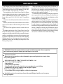
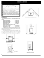
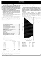
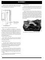
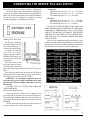
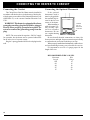
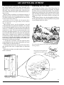
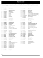
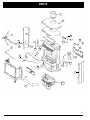
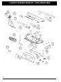
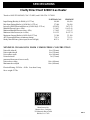
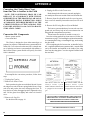
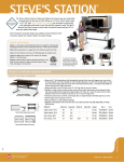
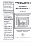
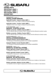
Installation & Operating Manual
The Harman Clarity 929 DV
Direct Vent Gas Stove
HA RM A N
R5
“Ce manuel est disponible en Français sur demande”
SAFETY NOTICE
PLEASE READ THIS ENTIRE MANUAL BEFORE YOU INSTALL AND USE YOUR NEW ROOM HEATER. FAILURE TO
FOLLOW INSTRUCTIONS MAY RESULT IN PROPERTY DAMAGE, BODILY INJURY, OR EVEN DEATH.
FOR USE IN THE U.S. AND CANADA. SUITABLE FOR INSTALLATION IN MOBILE HOMES
IF THIS HARMAN STOVE IS NOT PROPERLY INSTALLED, A HOUSE FIRE MAY RESULT. FOR YOUR SAFETY, FOLLOW
INSTALLATION DIRECTIONS.
CONTACT LOCAL BUILDING OR FIRE OFFICIALS ABOUT RESTRICTIONS AND INSTALLATION INSPECTION
REQUIREMENTS IN YOUR AREA.
CONTACT YOUR LOCAL AUTHORITY (SUCH AS MUNICIPAL BUILDING DEPARTMENT, FIRE DEPARTMENT, FIRE
PREVENTION BUREAU, ETC.) TO DETERMINE THE NEED FOR A PERMIT.
CETTE GUIDE D'UTILISATION EST DISPONIBLE EN FRANCAIS. CHEZ VOTRE CONCESSIONNAIRE DE HARMAN STOVE
COMPANY.
SAVE THESE INSTRUCTIONS.
R1
1
CONTENTS
INTRODUCTION ..........................................3
INSTALLATION ............................................4
Clearances...........................................4
Venting .................................................5
Requirements for Terminating the
Venting .............................................................6
Assembly .............................................7
Connecting to a Gas Supply ...............9
Connecting the Cordset .................. 10
Connecting the Thermostat ............ 10
Air Shutter Adjustment .................... 11
Monitoring the Gas Flame ............... 11
OPERATION ............................................... 12
How to Light the Fire ...................... 12
How to Turn Off the Fire ................ 12
Lighting Instructions....................... 13
M AINTENANCE......................................... 14
Removing the Glass ........................ 14
Replacing the Gasket ...................... 14
Cleaning the Glass .......................... 14
Inspecting the Venting .................... 14
Cleaning the Logset and Firebox... 14
PARTS LIST & DRAWING ................... 16-17
BURNER M ODULE ...................................18
SPECIFICATIONS ......................................19
APPENDIX A: FUEL CONVERSION ....... 20
APPENDIX B: ALTITUDE DE-RATING.. 21
VENTING REFERENCE CHARTS........22-23
WARRANTY ................................................ 24
Manufactured by:
Harman Stove Co.
352 Mountain House Road
Halifax, PA 17032
2
Tested by
Inchcape Testing/Warnock Hersey
8431 Murphy Drive
Middleton, WI 53562
INTRODUCTION
The Harman Clarity Direct Vent 929DV Gas Heater is a
listed gas-fired direct vent room heater tested by Inchcape
Testing/Warnock Hersey to ANSI standard Z21.88-2002,
CSA 2.33-M02, and CAN/CGA-2.17-M91.
The installation of the Clarity Direct Vent Gas Heater
must conform with local codes, or in the absence of local
codes, with National Fuel Gas Code, ANSI Z223.1 —
latest edition and CAN 1 B1-149.1 and .2 Installation
Code.
Also for use in mobile (manufactured) homes after home
is sited.
Mobile (manufactured) home installations must adhere
to the current edition of Title 24 CFR, part 3280, or CSA
Z240.4.
CAUTION: This appliance must be vented to the outside.
Installation and repair of the Clarity Direct Vent Gas
Heater should be done by a qualified service person. The
appliance should be inspected before use and at least annually by a qualified service person. More frequent cleaning may be required due to excessive lint from carpeting,
bedding material, etc. It is imperative that control compartments, burners, and circulating air passageways of the
Clarity be kept clean.
When operating your Harman Clarity Gas Heater, respect basic safety standards. Read these instructions carefully before you attempt to operate the heater. Failure to
do so may result in damage to property or personal injury
and may void the product warranty.
Consult with your local building code agency and insurance representative before you begin your installation to
ensure compliance with local codes, including the need for
permits and follow-up inspections.
Several issues must be addressed when selecting a suitable location for your Clarity Gas Heater. Observing required clearances to combustible materials, the proximity
to a safe chimney or venting system location, and the accessibility of the gas and electrical supply must all be considered. In addition, selecting a location that takes advantage of the building's natural air flow is also desirable to
maximize the heating effectiveness of the heater. In many
cases, this is a central location within the building.
WARNING: If the information in this manual is not followed exactly, a fire or explosion
may result causing property damage, personal injury or loss of life.
FOR YOUR SAFETY
Do not store or use gasoline or other flammable vapors and liquids in the vicinity of this
or any other appliance.
FOR YOUR SAFETY: WHAT TO DO IF YOU SMELL GAS
• Do not try to light any appliance.
• Open windows.
• Extinguish any open flame.
• Do not touch any electrical switch; do not use any phone in your building.
• Immediately call your gas supplier from a neighbor's phone.
Follow the gas supplier's instructions.
• If you cannot reach your gas supplier, call the fire department.
Installation and service must be performed by a qualified gas installer, service agency,
or the gas supplier.
3
INSTALLATION
IMPORTANT NOTICE
Due to high temperatures, the Clarity Direct Vent
Gas Heater should be located out of traffic and away
from furniture and draperies.
Children and adults should be alerted to the hazards of high surface temperatures and should stay
away to avoid burns or clothing ignition.
Young children should be carefully supervised
when they are in the same room as the appliance.
Clothing or other flammable materials should not
be placed on or near the Clarity Direct Vent Gas Heater.
4"
(1
00
m
m
)
4"
(1
m
m
)
Clearance from corner of unit to walls.
Clearances
The following clearances to combustibles must be observed:
Heater to left sidewall
9" (230 mm)
Heater to right sidewall
9" (230 mm)
Heater corner to walls
4" (100 mm)
Heater to back wall
3" (75 mm)
(measured from rear of heater to wall)
Heater to alcove ceiling
18" (460 mm)
Maximum alcove depth
14" (355 mm)
In addition to the clearances mentioned previously, adequate accessibility clearance for servicing and proper operation must be maintained.
If this appliance is installed directly on carpeting, vinyl
tile, or other combustible material other than wood flooring
the appliance shall be installed on a metal or wood panel
extending at least the full width and depth of the appliance.
18" (460 mm)
Clearance to alcove ceiling.
9" (230 mm)
9" (230 mm)
Sidewall clearance
3" (75 mm)
14" (355 mm)
Maximum alcove depth
Clearance to back wall
4
00
VENTING
The Clarity Direct Vent Gas Heater has been tested
and is listed for installation with Simpson Duravent GS venting components. The Simpson Duravent GS warranty will
be voided, and serious fire, health, or other safety hazards
may result from any of the following actions:
• Installation of any damaged Duravent GS component.
• Unauthorized modification of the Duravent GS System.
• Installation of any component part not manufactured or
approved by Simpson Duravent.
• Installation other than as instructed by Simpson Duravent
and the appliance manufacturer.
Consult your local building codes before beginning the
installation, and follow the manufacturer's instructions exactly. The following Simpson Duravent GS 4" X 6 5/8" venting components are approved for use with the Clarity Direct Vent Gas Heater.
SIMPSON DURA-VENT COMPONENT NO.
Basic Termination Kit .......................................................970
Horizontal Termination Kit A...........................................971
VerticalTermination Kit A.................................................973
Horizontal Square Termination Cap.................................984
VerticalTermination Cap ...................................................983
Snorkel Termination Cap, 36" Vertical Rise .....................981
Snorkel Termination Cap, 14" Vertical Rise .....................982
Vinyl Siding Standoff .......................................................950
Wall Thimble.....................................................................942
Round Ceiling Support/Wall Thimble Cover ..................940
Cathedral Ceiling Support Box ........................................941
Storm Collar ......................................................................953
Firestop Spacer.................................................................963
Adjustable Roof Flashing, 0/12-6/12 pitch .....................943
Steep Roof Flashing, 7/12-12/12 pitch.......................... 943S
Wall Strap .........................................................................988
Designer Series Trim Kits .......................... 3951, 3952, 3953,
3960, 3961, 3962
High Wind Vertical Termination Cap ...............................991
Low Profile Termination Cap............................................980
DIRECT VENT PIPE LENGTHS
DURA-VENT COMPONENT NO.
GALVANIZED
6" length
NA
9" length
NA
12" length
906
24" length
904
36" length
903
48" length
902
11-14 5/8" Adjustable
45° Elbow
945
90° Elbow
990
WARNING: The flow of ventilation air must not be
obstructed.
Horizontal and Vertical Venting Requirements
The maximum horizontal run allowed for the Clarity Direct Vent is 10 feet. The maximum vertical rise and maximum total vent length is 30 feet. The horizontal and vertical
lengths of venting must fall within the shaded portion of the
chart below:
Restr icto r
plates
sup plied
by
Har man
(Part No. G218) may be added in straight vertical installations only. For each 10' of vertical rise above the first 10',
one restrictor plate may be added. No more than two
restrictor plates may be used.
For venting systems that utilize one or two elbows (either 45° or 90°), restrictor plates
should not be used.
For the Clarity Direct Vent, the vent/
air intake termination clearances
above the high side of an
angled roof are as follows:
Vertical rise (feet)
Use Only Approved Venting
Horizontal run (feet)
BLACK
908B
907B
906B
904B
903B
902B
911B
945B
990B
The Clarity Direct Vent should be installed with no more
than 12 joints and 2 elbows. The elbows may be either 45°
or 90°.
The Clarity Direct Vent must not be connected to a chimney flue serving any other appliance.
Roof Pitch
Flat to 6/12
7/12 to 9/12
10/12 to 12/12
13/12 to 16/12
17/12 to 21/12
Feet
1
2
4
6
8
Meters
0.3
0.6
1.2
1.8
2.4
5
VENTING
Requirements for Terminating the Venting
As specified in CAN 1 B1-149 Installation Codes (currend
edition). Note: local codes or regulations may require different clearances.
2
A vent shall not terminate directly above a side-walk or
paved driveway which is located between two single family dwellings and serves both dwellings.
3
Only permitted if veranda, porch, deck, or balcony is fully
open on a minimum of 2 sides beneath the floor.
1
WARNING: Venting terminals must not be recessed
into a wall or siding.
In addition, the following must be observed:
A. The clearance above grade, or a veranda, porch, deck
or balcony must be a minimum of 12" (30 cm).1
B. The clearance to a window or door that may be opened
must be a minimum of 12" (30 cm).1
C. A 12" (30 cm) clearance to a permanently closed window is recommended to prevent condensation on the window.
D. The vertical clearance to a ventilated soffit located
above the terminal within a horizontal distance of 2 feet (60
cm) from the center-line of the terminal must be a minimum of 18" (46 cm).
E. The clearance to an unventilated soffit must be a minimum of 12" (30 cm).
F. The clearance to an outside corner is 9" (23 cm).
G. The clearance to an inside corner is 12" (30 cm).
H. A vent must not be installed within 3 feet (90 cm)
above a meter/regulator assembly when measured from the
horizontal center-line of the regulator.1
I. The clearance to service regulator vent outlet must be a
minimum of 6 feet (1.8 m).1
J. The clearance to a non-mechanical air supply inlet to
the building or the combustion air inlet to any other appliance must be a minimum of 12 feet (30 cm).1
K. The clearance to a mechanical air supply inlet must be
a minimum of 6 feet (1.8 m).1
L. The clearance above a paved sidewalk or a paved
driveway located on public property must be a minimum of
7 feet (2.1 m).1,2
M. The clearance under a veranda, porch, deck or balcony must be a minimum of 12 inches (30 cm).1,3
Connecting To An Existing Chimney
The Clarity may be connected to an existing masonry chimney by using a Simpson Dura-Vent conversion kit #934.
With this kit and a 4" flex linner in the chimney the
flue gases exit through the 4" linner and the outside
air comes down the chimney in the space between
the chimney and the linner. This method allows you
to install the Clarity your chimney and still get the
added efficiency provided by direct venting.
The use of an existing chimney as an
air intake is not covered under the ANSI Z21.50-1996.
CGA 2.22-M96 test methods and the resulting ITS/WHI
product certfication: The code Authority Having Jurisdiction must be consulted prior to proceeding.
I ns ide
Corner
Det ail
G
V
D
A
H
V E
C
B
LV
V
F
B
Fixed
Closed
B
V
Op enab le
V
B
B
V
V
Fixed
Closed
Openable
J
A
B
M
V
A
6
V
= Vent terminal
A
= Air supply inlet
= Area where terminal is not permitted
K
A
ASSEMBLY
The Clarity is shipped from the factory with the log set
packed inside the firebox. To prepare the stove for installation, the log set must be unpacked, the appropriate burner
system module for either natural gas or propane installed,
and the logs installed.
Removing the Glass Front
NOTE: The glass front is heavy. Be prepared for its
weight when lifting it to avoid damage during removal.
The wing doors on each side are held closed by magnets. Push on each door to open it. Loosen the wing nut on
each of the two spring-loaded levers. Grasp each lever and
push to the rear to disengage the front. To keep the levers in
the disengaged position, tighten the wing nuts. Lift the glass
front slightly and remove it from the stove. Set the glass
aside in a safe place where it will not be damaged.
Remove and Unwrap the Log Set
As shown in the photo in the right column, the log set
consists of a back log (1), a center log that has a pilot-viewing port in the left end (2), two ember strips (3), and a branch
that rests on top (4).
In addition, there are two side brick panels and a back
brick panel.
The log set components are shipped from the factory
individually wrapped and packed inside the stove. Take them
out of the stove, then carefully remove the wrapping. Handle
the logs gently as they may be damaged easily.
1
2
3
The front is released
when spring-loaded
levers on the left
and right sides are
pushed to the rear
WARNING: Do not abus e the Clarity's glass
by striking, slamming, or similar trauma. Do not
operate the Clarity Gas Heater with the glass
panel removed, cracked or broken. Use only
glass supplied by Harman and approved for use
with this heater. Do not us e substitute materials. Replacement of the panel s hould be done
by a licensed or qualified service person.
4
3
Installing the Burner System Module
The burner system module may be installed into the firebox as an integrated unit, and it may help to have an assistant
who can assist in guiding the components into position and in
making sure that the module does not sit on any wiring components.
Hold the module at a slight angle, then lower it through the
opening and rotate upright until it is in position.
Reach underneath and install one of the wing nuts, finger
tight. Then check to see that the module is seated correctly.
A sealing gasket affixed to the bottom of the module's base
plate will cause the log support plate to be elevated slightly
above the plane of the firebox bottom plate. When the two
wing nuts are tightened, this gasket will be compressed and a
correct fit will be indicated by the log support plate becoming
flush with the bottom of the firebox.
Install wing nut
on threaded stud
7
ASSEMBLY
With the module installed and secured, reach through
the side access ports and plug in the electrical connections.
(Two AMP Mate-N-Lok connectors).
Install the Branch
Orient the branch with the forked end toward the left
rear of the stove and slip it over the two locator pins, one on
top of the back log and the other on the top of the center log.
Secure the Glass Front
NOTE: The glass front is heavy. Lift it carefully to prevent damage. Center the glass on the opening and suspend
it in place by placing the the tab hooks over the top edge of
the opening. Loosen the wing nuts that hold the spring-loaded
levers in place. Press the glass slightly against the stove to
confirm that it seats properly, then press it firmly against the
front while pulling the levers forward to engage them. Tighten
the wing nuts.
The two electrical
connectors may be
reached through the
side access port
Install the Back Log and Back Brick Panel
These two components are installed as a single piece.
Rest the back brick panel on the shelf located on the back
side of the back log, and center it. Holding the two pieces as
a single unit, tilt the top forward slightly and manuever it
over the top of the rear burner—taking care that the top
corners clear the front opening. Place it snugly against the
back wall and center it.
Install the Side Brick Panels
These slide into place along each side and are held by
friction. The notch in each panel faces the back. Install one
side, and then the other.
Install the Ember Strips
The ember strips rest against the front of the firebox
and should fit snugly. Guide them toward you and to the
outside until they fit snugly. Check the air slot in the inside of
the ember strips to confirm that they do not obstruct it.
Install the Center Log
The center log goes all the way to the back and should
be centered. When properly positioned, there should be an
even gap along the front of the center burner in the cavity in
the log. A small portion of the log support frame will be
revealed.
The center log has a round viewing port in the left end
through which the pilot can be observed.
8
The complete log set with all logs in the correct position.
CONNECTING THE HEATER TO A GAS SUPPLY
Burn Only the Fuel for which the Heater is Equipped
The Clarity Direct Vent will burn either natural gas or
propane, but requires a dedicated burner system module for
either fuel. The label on the burner system module indicates
the fuel for which it is equipped. A second label, located
near the rating plate, also indicates the fuel type.
Making The Connection
The gas inlet is located at
the bottom right rear of the
stove. The inlet fitting is a 1/
2" female flare flexible pipe.
A separate gas shut-off
valve an d a 1/8" N.P.T.
plugged tapping should be
installed immediately upstream of the connection to
the appliance.
The Clarity Direct Vent
Gas Heater must be disconnected from the gas supply piping during any pressure testing of that system at pressures in excess of 1/2 psig (3.5
kPa).
The Clarity gas control valve must be in the OFF position
during any pressure testing of the gas supply system at pressures equal to or less than 1/2 psig (3.5 kPa).
WARNING: To avoid pipe compounds from entering into the gas train, apply compounds only to male
pipe threads and do not apply compound to the first
two threads.
CAUTION: TEST ALL JOINTS FOR LEAKS BEFORE OPERATING
Natural Gas:
Maximum inlet pressure 7.0" w.c. (1.74 kPa)
Minimum inlet pressure 5.0" w.c. (1.25 kPa)
Gas manifold pressure 3.5" w.c. (0.87 kPa)
LPG Gas:
Maximum inlet pressure 13" w.c. (3.24 kPa)
Minimum inlet pressure 11" w.c. (2.74 kPa)
Gas manifold pressure 10" w.c. (2.49 kPa)
DO NOT USE THIS HEATER IF ANY PART HAS
BEEN UNDER WATER OR EXPOSED TO MOISTURE
CORROSION. IMMEDIATELY CALL A QUALlFlED
SERVICE TECHNICIAN TO INSPECT THE HEATER
AND REPLACE ANY PART OF THE CONTROL SYSTEM AND ANY GAS CONTROL WHICH HAS BEEN
UNDER WATER.
Once you have installed the appropriate burner system
module, fill out the installer fuel label that was included with
the module, peel off the self-adhesive backing material, and
affix the label to the wing door near the rating plate.
RECOMMENDED GAS PIPE DIAMETER
Pipe Length Schedule 40 Pipe
(Feet)
Inside Diameter
Tubing, Type L
Outside Diameter
N.G.
L.P.
N.G.
L.P.
0-10
1/2"
1.3 cm
3/8"
1.0 cm
1/2"
1.3 cm
3/8"
1.0 cm
10-40
1/2"
1.3 cm
1/2"
1.3 cm
5/8"
1.6 cm
1/2"
1.3 cm
40-100
1/2"
1.3 cm
1/2"
1.3 cm
3/4"
1.6 cm
1/2"
1.3 cm
100-150
3/4"
2.0 cm
1/2"
1.3 cm
7/8"
2.3 cm
3/4"
2.0 cm
NOTE: NEVER USE PLASTIC PIPE. CHECK TO CONFIRM
WHETHER YOUR LOCAL CODES ALLOW COPPER
TUBING OR GALVANIZED PIPE.
Gas Pressure Requirements
Correct gas pressure and the use of a properly sized
gas supply line are essential for the safe and efficient performance of this appliance. Make sure that the plumber or
gas supplier checks the gas supply line and gas pressure at
installation.
NOTE: Improper gas pressure can affect heater performance, flame color, or cause pilot outage.
9
CONNECTING THE HEATER TO CORDSET
Connecting the Cordset
Connecting the Optional Thermostat
The Clarity Direct Vent Gas Heater must be installed in
accordance with local codes or, in the absence of local codes,
with the most recent edition of the National Electrical Code
ANSI/NFPA 70, or the current Canadian Electrical Code
C22.1.
If the o ptio nal
thermostat is used, it
must be plugged into
the terminal strip located in the left rear
corner of the heater.
Terminal
When installing a
strip for
millivolt control systhermostat
tem, use only a speconnection
cial low resistance
thermostat. Do not
use a regular heating Rear view of Clarity
thermostat.
Be sure that all electrical connections are clean, free
from corrosion, and tight. Inspect connections periodically
to confirm that no corrosion has built up over time.
When properly installed and maintained, a millivolt control system should give many years of trouble-free service.
It is important to use wire of a gauge proper for the
length of the wire:
WARNING: This heater is equipped with a threepronged grounding plug that should be plugged
directly into a properly grounded receptacle. Do
not cut or remove the grounding prong from the
plug.
NOTE: The convection fan requires a 120 VAC supply
for operation, but the heater can be operated without the
fan as in the case of a power outage.
Plug the 3-prong grounded electrical cord plug into the
wall.
RECOMMENDED WIRE GAUGES
Maximum
Wire
Length
Gauge
100'
14
60'
16
40'
18
25'
20
15'
22
10
AIR SHUTTER ADJUSTMENT
AIR SHUTTER ADJUSTMENT
Monitoring the Gas Flame
The final step of the installation is to check the flame pattern, which should resemble the pattern illustrated in the
right column: The flames should be relatively well-defined
and stable. They should be bright yellow with a blue base
where attached to the burner ports, and should not look orange or sooty.
Start the heater according to the directions on page 12
and allow the heater to burn for approximately 15 minutes.
The flames will increase in length and become more yellow
in color as the Clarity heats up.
If the flames do not resemble the description above
and the illustration in the right column, the air shutters
may be adjusted.
Three separate screws—one for each burner—are used
to adjust the flames for a particular installation. Two of them
are accessible through the side access port on the right side
of the stove. The third is accessible from the front when the
control door is open. The screws may become hot to the
touch after prolonged operation. Use a 3/16" Allen wrench
to avoid contact if hot. For best results when fine-tuning the
flame picture, initially leave the middle screw unchanged
from its factory setting. Turn the other two screws as needed
to increase or decrease the brightness and length of the
flame: turning counterclockwise will increase the flame; turning clockwise will decrease the flame.
1. To adjust the rear burner, open the right wing door,
reach through the side access port, and turn the rear screw
to adjust flame (see directions above).
2. To adjust the front burner, first open the control door,
then turn the front screw to adjust flame (see directions
above).
Repeat the procedure as needed until the desired flame
effect is achieved.
Periodically, the flames of the Clarity Direct Vent Gas
Heater should be checked while it is operation. The flames
should be relatively well-defined and stable. They should be
bright yellow with a blue base where attached to the burner
ports. The flames should not look orange or sooty. Portions
of the logs will glow red when the flames are properly adjusted.
If you find the flames to be other than that described here,
do not operate the heater. Consult a qualified service person
or your Harman dealer for advice.
The Clarity flame pattern will resemble this when the unit is
burning properly.
The properly-burning pilot will
resemble the illustration to the
right.
Rear Burner
Center burner
Front burner
Air adjustment
screws
11
OPERATION
HOW TO LIGHT THE FIRE
1. STOP! Read the safety information on the left side of
the panel on page 13.
2. If using the optional thermostat, set thermostat to the
lowest setting.
3. Turn off electric power to the appliance.
4. Turn the ON-OFF/THERMOSTAT switch to the OFF
position.
5. Push in the gas control knob slightly and turn it clock-
wise to "OFF." NOTE: The knob cannot be turned from
"PILOT" to "OFF" unless it is pushed in slightly. Do not
force it.
6. Wait five (5) minutes to clear out any gas. If you then
smell gas, STOP! Follow "B" in the safety information on
the top of page 13. If you don't smell gas, go to the next
step.
7. Set the High-Low Regulator to High by turning it fully
counterclockwise.
8. Press in the gas control knob slightly and turn counterclockwise to "PILOT."
9. Find the pilot by looking through the round opening on
the left end of the center log.
10. Push the control knob fully down and hold. Immediately push the red piezo ignitor button to light the pilot. It is
normal to have to push the red button several times before
the pilot ignites. Continue to hold the control knob in for
about one (1) minute after the pilot is lit. Release the knob
and it will pop back up. Pilot should remain lit. If it goes out,
repeat steps 5 through 9.
•If the knob does not pop up when released, stop and
immediately call your service technician or gas supplier.
•If the pilot will not stay lit after several tries, turn the
gas control knob to "OFF" and call your service technician
or gas supplier.
11. Turn the gas control knob counterclockwise to "ON."
12. Place the ON-OFF/THERMOSTAT switch in the ON
position or in the THERMOSTAT position if the optional
thermostat is used.
13. Turn on the electric power to the heater.
14. Set the optional thermostat to the desired room temperature.
12
15. Set the High-Low Regulator to desired setting: turn
fully counterclockwise for High and fully clockwise for Low.
NOTE: An odor resulting from the initial heating of new
materials in your heater is not unusual during the first fire,
and in most cases will disappear after an hour or two.
HOW TO TURN OFF THE FIRE
1. If using optional thermostat, set thermostat to the lowest position.
2. Turn off the electric power to the appliance.
3. Turn the ON-OFF/THERMOSTAT switch to the OFF
position.
4. Push in the gas control knob slightly and turn it clockwise to “OFF.”
NOTE: The knob cannot be turned from “PILOT” to
“OFF” unless it is pushed in slightly. Do not force it.
SAFETY/LIGHTING LABEL
13
MAINTENANCE
A qualified service person recommended by your Harman dealer should conduct an annual inspection and maintenance of your Clarity, its venting, and the installation to
keep it running safely and efficiently. The following procedures should be performed only by a qualified service person. The gas supply should be turned off whenever a maintenance procedure is performed.
If the glass front, side doors, or front access door are
removed for servicing, they must be replaced prior to operating the Clarity.
Removing the Glass Front for Replacement
Refer to page 7 for directions on removing the glass front.
Use only authorized Harman replacement glass components
available from your Harman dealer.
Replacing the Gasket
The Clarity has 5/8" diameter fiberglass gasket in the front
door. Should it ever need replacement, use only the proper
replacement gasket that is available from your Harman dealer.
To replace the gasket, follow this procedure.
1. Open the door
2. Remove the existing gasket and clean its channel with
a scraper or wire brush.
3. Lay a thin bead of high temperature silicone the entire
length of the channel.
4. Lay the gasket in the channel with sufficient pressure
that is stays in place.
5. Trim the excess from the end of the gasket so that it
butts snugly against the other end without leaving a gap.
Seal the end joint with high temperature silicone.
6. Close the door and apply firm pressure to seat the gasket evenly throughout.
Cleaning the Glass
The glass may be cleaned with ordinary household glass
cleaner and a soft cloth or paper towel.
WARNING: Never clean the glass when it is hot.
Do not use abrasive cleaners on the glass.
Inspecting the Venting
An inspection of both the inner and outer pipes of the
venting system should be made during the annual service
appointment. They must have no blockage and be in good
repair. The vent manufacturer's instructions may provide
specific suggestions or details on vent inspection. Any sections that are taken apart for the inspection must be reassembled and sealed as required.
14
Cleaning the Log Set and Firebox
During the annual inspection and maintenance appointment, the service person should clean dust, lint, and any light
accumulation from the logs and the firebox area. An extrasoft brush should be used on the logs as they are extremely
fragile; a vacuum cleaner may be used on the firebox. If at
any time the logs cannot be removed or installed without
forcing, the cause must be found. The logs must never be
forced.
Removing the Front
See directions on page 7.
Removal & Re-installation of the Log Set for Cleaning
CAUTION: The ceramic logs are durable when handled
and installed properly. However, they are delicate and may
be damaged easily if not handled with care. Handling damage to the ceramic logs is not covered by warranty.
DO NOT HANDLE LOGS WHILE THEY ARE HOT.
ALLOW PLENTY OF TIME FOR THE STOVE TO
COOL COMPLETELY BEFORE HANLDING.
Remove the Branch
Detach the branch from the two locator pins and remove it. Brush it gently and carefully place it to one side.
Remove the Center Log
Lift the center log and remove it. Brush it gently and
carefully place it to one side with the branch.
Remove the Ember Strips
Carefully remove the ember strips, clean them, and place
them with the other logs.
Remove the Side Brick Panels
Carefully remove first one side panel, and then the other.
Clean and place to side.
Remove the Back Log and Back Brick Panel
Finally, carefully remove these two components as a single
piece. Brush them gently and place them to the side.
Finish the procedure by vacuuming the interior of the firebox, then re-install the logs and secure the glass front following the procedures on page 8.
WIRING DIAGRAM
Clarity Direct Vent Wiring Diagram
The Clarity Direct Vent gas heater, when installed, must be electrically grounded in accordance with current
local codes or, in the absence of local codes, with the current edition of National Electrical Code, ANSI/NFPA
70 in the United States or the current Canadian Electrical Code CSA 22.1 in Canada.
15
PARTS LIST
The following replacement parts for your Harman Clarity Direct Vent are available from your Harman dealer.
ID# Part No.
1.
1-89-08250
2.
3-44-08294
3.
3-40-3849239
4.
3-40-08286
5.
6.
7.
8.
9.
10.
11.
12.
13.
14.
15.
16.
17.
18.
19.
20.
21.
22.
23.
24.
25.
26.
27.
28.
29.
30.
31.
32.
33.
34.
35.
36.
37.
38.
16
Part
DVG weldment
Starting Collar Gasket
Starting Collar
39.
40.
41.
3-40-08235
3-40-08236
3-40-08237
1/2” gasinlet flex
Rearlog
Front log
Top log
42.
43.
44.
45.
3-40-08401
3-40-08232
3-40-08233
3-40-08234
Ember strip
Left brickpanel
Right brick panel
Rearbrickpanel
46.
47.
48.
49
3-40-08693
3-40-08225
3-40-08226
3-31-965487
Front burner tube
Center burner tube
Rear burner tube
Ext. spring
50.
51.
52.
53.
3-40-00141
3-31-08225
3-20-408412
3-20-326007
Formed wire gold trim
Magnet
Snap discfan control
3-20-326004
3-20-00907
3-42-2312
3-44-1086405
3-43-4103
3-40-120
3-40-121
1-10-08285
3-44-08287
3-40-820628
3-40-82057
3-40-57356
3-40-64347
3-40-64739
3-40-57271
3-40-57356
3-40-57753
3-40-08231
3-40-08714
21” harnessw/terminal block
Powercord
Saftey switch
Glass gasket
5/8” tight knit rope for door
Gold plateddoor frame
13-3/4” X 19” glass
5-3/4” X13-3/4” glass
Distribution blower w/ends
Pilot tower gasket
NGvalve
LPvalve
#56 orifice, LP front/NG center
#47 orifice, NG front
#39 orifice, NG rear
#71 orifice, LP center
#56 orifice, LP center
#53 orifice, LP rear
Piezocable
Pilot, NG
3-40-08715
3-40-08906
3-40-08220
3-31-08282
3-31-08283
3-31-08234
3-30-310056082
3-20-326006
3-20-326005
3-20-08221
3-20-08219
2-00-08281
0-46-250
1-00-08313
1-00-08314
54a 2-00-4200
54b.. 2-00-4201
55. 1-00-08301
56. 2-00-4172
57. 2-00-4173
58a. 1-10-08265-1
58b. 1-10-08265-2
59a. 2-00-4138-1
60. 2-00-4138-2
60b. 1-10-08287
61.
62.
63.
64.
65.
66.
67.
1-10-08258
1-10-08262-1
1-10-08262-2
2-00-4162
2-00-4210
2-00-4177
2-00-4169
Pilot, LP
Thermocouple
Piezoignitor
o
90 brass elbow
1/4” tp 3/8” male compression fitting
3/8” tp 3/8” male compression fitting
BHSCS 5mm X 8mm for valve
18”valve harness
Harnessw/VSC
On-Off rocker switch
Thermopile
3/8” tubing
1/4” tubing
Valve change-overassembly, NG
Valvechange-overassembly, LP
Saftey switchbracket, lower
Safteyswitchbracket, upper
Saftey switch cable/ pin assembly
Baffle
Snap discfan control bracket
Latch arm, left
Latch arm, right
Latch cam, left
Latchcam,right
Front door assembly
Top
Left wing door
Right wing door
Control door
Control heat shield
Lower rearaccess cover
Base trim
PARTS
Clarity
Parts
3
61
62
55
17
54a
21
16
57
54b
18
17
16
66
58a
59a
56
16
27
17
59b
58b
65
60
1
64
63
24
52/53
67
17
CLARITY BURNER MODULE : EXPLODED VIEW
38
49
40
37
14
13
12
52
33
41
32
31
51
50
43
44
48
18
42
SPECIFICATIONS
Clarity Direct Vent 929DV Gas Heater
Tested to ANSI Z21.88-2002, CSA 2.33-M02, and CAN/CGA 2.17-M91.
Input Rating (Btu/hr) (0-4500 ft) (0-1375 m)
Min. Input Rating (Btu/hr) (0-4500 ft) (0-1375 m)
Injectors (DMS) (front/middle/rear) (0-4500 ft) (0-1375 m)
Manifold Pressure (in w.c./kPa)
Minimum Manifold Pressure (in w.c./kPa)
Minimum Inlet Pressure (in w.c./kPa)
Maximum Output (Btu/hr) (0-4500 ft) (0-1375 m)
AFUE (seasonal efficiency; minimum venting)
Steady State Efficiency (max. input, blower on High)
NATURAL GAS
40,000
27,000
45/56/39
3.5/0.87
1.7/0.42
5.0/1.25
31,200
71.6 %
80.2 %
PROPANE
40,000
28,000
56/71/53
10.0/2.49
5.9/1.47
11.0/2.74
32,100
73.8 %
83.3 %
MINIMUM CLEARANCES FROM COMBUSTIBLE CONSTRUCTION
Unit to left sidewall
Unit to right sidewall
Unit corner to walls
Unit to backwall
(measured from rear of stove to wall)
Unit to alcove ceiling
Maximum alcove depth
9 in. (230 mm)
9 in. (230 mm)
4 in. (100 mm)
3 in. (75 mm)
18 in. (460 mm)
14 in. (460 mm)
Electrical Rating: 120 Volts 60 Hz Less than 1 Amp
Stove weight: 237 lbs.
Manufactured by:
Harman Stove Company
352 Mountain House Road
Halifax, PA 17032
19
8-2-96
APPENDIX A
Converting the Clarity Direct Vent
from One Gas to Another in the Field
NOTE: THE CONVERSION SHALL BE CARRIED OUT IN ACCORDANCE WITH THE REQUIREMENTS OF THE PROVINCIAL OR LOCAL
AUTHORITIES HAVING JURISDICTION AND IN
ACCORDANCE WITH REQUIREMENTS OF THE
CURRENT EDITION OF THE NATIONAL FUEL
GAS CODE, ANSI Z223.1 or the CAN/CGA-B149 INSTALLATION CODES.
Conversion Kit Components
• Burner system module
• Conversion label
The Clarity is designed to burn either natural gas or
propane, but requires a dedicated burner system module for
either fuel. Conversion to the alternate fuel is a simple matter of replacing one burner system module with another. A
label on the burner system module will specify for which
fuel it is intended.
4. Unplug the Electrical Connectors
Reach through the side access port and unplug the
two multi-pin connectors and the white lead from the fan.
5. Remove from the theaded studs the two wing nuts
that secure the module from underneath, one on each
side.
6. Remove the Existing Burner System Module
The burner system module may be removed as an integrated unit, and it may help to have an assistant who can
help guide the components into position.
Tilt and rotate the module as needed to remove it.
Once the existing module has been removed, follow the
instructions on page 7 for installing the replacement module,
re-connecting the wiring, re-installing the logs, and securing
the glass front.
After completing the fuel conversion, an installer fuel label—supplied with the burner system module—must be filled
out by the installer and attached to the inside of the wing
door near the rating plate. Cover the original fuel label with
the new label.
To accomplish the conversion procedure, follow these
steps.
1. Unplug the Cordset
2. Remove the Glass Front
Push open the wing door on each side of the unit. Loosen
the wing nut on each of the two spring-loaded levers. Grasp
each lever and push to the rear to disengage the front. To
keep the levers in the disengaged position, tighten the wing
nuts. Lift the glass front slightly and remove it from the
stove.
3. Remove the Log Set
See the directions on page 14.
The abo ve l abel on the
Cl arit y's burner syst em
module indicates that the unit
is equipped to burn natural
gas.
The abo ve l abel on the
Cl arit y's burner syst em
module indicates that the unit
is equipped to burn propane.
CAUTION: LABELALLWIRES PRIOR TO DISCONNECTION
WHEN SERVICING CONTROLS. WIRING ERRORS CAN
CAUSE IMPROPER AND DANGEROUS OPERATION.
VERIFY PROPER OPERATION AFTER SERVICING.
SEE WIRING DIAGRAM ON PAGE 15.
20
APPENDIX B
De-rating for High Altitude
For U.S. installations, the Clarity Direct Vent is approved for elevations up to 2000 feet using the factory-installed burner
injectors. At elevations above 2000 feet, U.S. codes require a decrease in the input rating by changing the burner injectors to
a smaller size. The chart below lists by part numbers the appropriate injectors for both LP and natural gas at various altitudes.
For Canadian installations, the Clarity Direct Vent is approved for elevations up to 1375 meters (4500 feet). When installing
the Clarity Direct Vent at altitudes above 1375 meters (4500 feet), consult the local gas distributor or the authority having
jurisdiction for proper rating methods.
NOTE: The difference in altitude derating requirements for the U.S. and Canada is simply a result of differences in testing
standards between the two countries.
If the installer must convert the unit to adjust for varying altitudes, an information sticker like the one to the right must be
filled out and affixed to the appliance at the time of conversion.
NATURAL GAS
Altitude
0-2000'
2000-3000'
3000-4000'
4000-5000'
5000-6000'
6000-7000'
7000-8000'
8000-9000'
Front
Injector
47
48
49
49
50
50
51
51
Harman
Part No.
Standard
3-40-25848
3-40-25849
3-40-25849
3-40-25850
3-40-25850
3-40-25851
3-40-25851
Center
Injector
56
56
56
57
57
57
58
58
Harman
Part No.
Standard
Standard
Standard
3-40-25857
3-40-25857
3-40-25857
3-40-25858
3-40-25858
Rear
Injector
39
40
41
42
42
43
43
44
Harman
Part No.
Standard
3-40-25840
3-40-25841
3-40-25842
3-40-25842
3-40-25843
3-40-25843
3-40-25844
Nominal Btu
Input Rate
40,000
38,400
36,900
35,400
34,000
32,600
31,300
30,100
PROPANE
Altitude
Front
Harman
Injector Part No.
Center Harman
Injector Part No.
Rear
Harman
Injector Part No.
Nominal Btu
Input Rate
0-2000'
2000-3000'
3000-4000'
4000-5000'
5000-6000'
6000-7000'
7000-8000'
8000-9000'
56
56
56
57
57
57
58
58
71
71
71
71
71
71
71
71
53
54
54
54
55
55
56
56
40,000
36,900
36,900
35,400
32,600
32,600
30,100
30,100
Standard
Standard
Standard
3-40-25857
3-40-25857
3-40-25857
3-40-25858
3-40-25858
Standard
Standard
Standard
Standard
Standard
Standard
Standard
Standard
Standard
3-40-25854
3-40-25854
3-40-25854
3-40-25855
3-40-25855
3-40-25856
3-40-25856
THE CONVERSION SHALL BE CARRIED OUT
BY A MANUFACTURER'S AUTHORIZED REPRESENTATIVE IN ACCORDANCE WITH THE REQUIREMENTS OF THE MANUFACTURER, PROVINCIAL OR TERRITORIAL AUTHORITIES HAVIN G J URISDICTION AND IN AC COR DAN CE
WITH THE REQUIREMENTS OF THE CURRENT
EDITION OF CAN/CGA-B141.1 OR CAN/CGAB141.2 INSTALLATION CODES.
21
CROSS REFERENCE CHART - Selkirk Direct-Temp & Simpson Dura-Vent Direct Vent GS
Selkirk Direct- TempTM Simpson Dura-Vent Direct Vent GS@
Stock No.
4DT -6
4DT -6B
4DT -9
4DT -9B
4DT -12
4DT -12B
4DT -18
4DT -18B
4DT -24
4DT -24B
4DT -36
4DT -36B
4DT -48
4DT -48B
4DT -AJ
4DT -AJB
4DT -EL45
4DT -EL45B
4DT -EL90
4DT -EL90B
4DT -AA
4DT -RD
4DT -CS
4DT -CSS
4DT -WS/B
4DT -OS
4DT -WT
4DT -FS
4DT- TP
4DT -HKA
4DT -HKB
4DT -V KC
4DT -HVC
4DT -HHC
4DT -SC
4DT -AF6
4DT -AF12
4DT -VS
4DT -VSP
4DT -ST14
4DT -ST36
22
Description
6" Pipe Length, Galvanized
6" Pipe Length, Black
9" Pipe Length, Galvanized
9" Pipe Length, Black
12" Pipe Length, Galvanized
12" Pipe Length, Black
18" Pipe Length, Galvanized
18" Pipe Length, Black
24" Pipe Length, Galvanized
24" Pipe Length, Black
36" Pipe Length, Galvanized
36" Pipe Length, Black
48" Pipe Length, Galvanized
48" Pipe Length, Black
Adjustable Length, 11"-14", Galv.
Adjustable Length, 11"-14" Black
45° Elbow, Galvanized
45° Elbow, Black
90° Elbow, Galvanized
90° Elbow, Black
Appliance Adaptor, Black
Restriction Disc
Ceiling Support
Cathedral Support Box
Wall Support/Band
Offset Support
Round Wall Thimble, Black
Firestop Spacer
Trim Plate, Black
Horizontal Term. Kit A
Horizontal Term. Kit B
Vertical Termination Kit
High Wind Vertical Cap
High Wind Horizontal Cap
Storm Collar
Adjustable Flashing, 0/12-6/12
Adjustable Flashing, 6/12-12/12
Vinyl Siding Standoff
Vinyl Siding Shield Plate
Snorkel Termination 14"
Snorkel Termination 36"
Stock
908
908B
907
907B
906
906B
n/a
n/a
904
904B
903
903B
902
902B
911
911
945
945B
990
990B
n/a
929
949
941
988
989
942
963
n/a
970
971
978
991
985
953
943
943S
950
n/a
982
981
Description No.
6" Pipe Length, Galvanized
6" Pipe Length, Black
9" Pipe Length, Galvanized
9" Pipe Length, Black
12" Pipe Length, Galvanized
12" Pipe Length, Black
n/a
n/a
24" Pipe Length, Galvanized
24" Pipe Length, Black
36" Pipe Length, Galvanized
36" Pipe Length, Black
48" Pipe Length, Galvanized
48" Pipe Length, Black
Adjustable Length, 11"-14", Galv.
Adjustable Length, 11"-14", Black
45° Elbow, Galvanized
45° Elbow, Black
90° Elbow, Galvanized
90° Elbow, Black
n/a
Restrictor Disc
Round Ceiling Support / Wall Thimble Cover
Cathedral Ceiling Support Box
Wall Stap
Elbow Strap
Wall Thimble
Ceiling Firestop
n/a
Basic Horizontal Term. Kit
Horizontal Termination Kit A
Vertical Termination Kit
High Wind Termination Cap
Horiz. Square High Wind Termination
Storm Collar
Adj. Roof Flashing 0/12-6/12
Steep Roof Flash. 7/12-12/12
Vinyl Siding Standoff
n/a
Snorkel Termination Cap 14"
Snorkel Termination Cap 36"
Secure Vent Direct Vent System
Secure Vent Direct Vent System
4" X 6-5/8" AND 5" X 8"
Description
SECURE Simpson Dura-Vent SECURE Simpson Dura-Vent
VENT
Direct Vent GS
VENT
Direct Vent GS
CAT.NO.
Stock No.
4"
CAT.NO.
Stock No.
5"
Length 6" (galvalume)
SV4L6
908
SV5L6
1208
Length 6" (black)
SV4LB6
908B
SV5LB6
1208B
Length 12" (galvalume)
SV4L12
906
SV5L12
1206
Length 12" (black)
SV4LB12
906B
SV5LB12
1206B
Length 24" (galvalume)
SV4L24
904
SV5L24
1204
Length 24" (black)
SV4LB24
904B
SV5LB24
1204B
Length 36" (ga’valume)
SV4L36
903
SV5L36
1203
Length 36" (black)...
SV4LB36
903B
SV5LB36
1203B
Length 48" (galvalume)
SV4L48
902
SV5L48
1202
Length 48" (black)
SV4LB48
902B
SV5LB48
1202B
Adjustable length (galvalume) (adjustable 6")
SV4LA
N/A
SV5LA
N/A
Adjustable (black) length (adjustable 6")
SV4LBA
N/A
SV5LBA
N/A
Adjustable length (galvalume) (adjustable 12")
SV4LA12
N/A
SV5LA12
N/A
Adjustable (black) length (adjustable 12")
SV4LBA12
N/A
SV5LBA12
N/A
Adjustable length (galvalume) (adjustable 24")
SV4LA24
917
SV5LA24
1217B
Adjustable (black) length (adjustable 24")
SV4LBA24
917B
SV5LBA24
1217B
Swivel 45o elbow (galvalum e)
SV4E45
945G
SV5E45
1245G
Swivel 45 elbow (black)
SV4EB45
945BG
SV5EB45
1245BG
Rigid 45o elbow(black)
SV4EBR45
945B
SV5EBR45
1245B
Swivel 90o elbow (galvalum e)
SV4E90
990G
SV5E90
1290G
Swivel90o elbow (black)
SV4EB90
990BG
SV5EB90
1290BG
Rigid 90 elbow(black)
SV4EBR90
990B
SV5EBR90
1290B
Adjustable decorative square cathedral support
SV4CSB
941
SV5CSB
1241
Collar for decorative square cathedral support
SV4AC
N/A
SV5AC
N/A
Decorative black plate (square)
SV4PF
940
SV5PF
1240
Universal support
SV4SU
989
SV5SU
1289
Floor support
SV4SD
N/A
SV5SD
N/A
Roof Brace
SV4BS
N/A
SV5BS
N/A
Roof Support
SV4ST
NIA
SV5ST
NIA
Wall band
SV4BM
988
SV5BM
1288
Attic radiation shield
SV4RSA
N/A
SV5RSA
NIA
Wall radiation shield
SV4RSM
942
SV5RsM
1242
Firestop
SV4BF
963
SV5BF
1263
Flat roof flashing (storm collarincluded)
SV4F
943F
SV5F
1243F
Adjustableroof flashing1/12-7/12(storm collarincluded)
SV4FA
943
SV5FA
1243
Adjustable rooff1ashing 8/12 -12/12 (storm collar included)
SV4FB
943S
SV5FB
1243S
Storm Collar
SV4FC
953
SV5FC
1253
Vinyl shield protector
SV4VS
950
SV5VS
1250
Restrictordisk
SV4RD
929
SV5RD
NIA
VERTICAL TERM INATION CAP
SV4CGV
980
SV5CGV
1280
HORIZONTAL TERMINATION CAP
SV4CHC-1
984
SV5CHC-1
1284
SNORKEL CAP 14"
SV4STC14
982
SV5STC14
1282
SNORKEL CAP 36"
SV4STC36
981
SV5STC36
1281
o
o
23
HARMAN GOLD WARRANTY
HARMAN GOLD WARRANTY
6 YEAR TRANSFERABLE LIMITED
WARRANTY (Residential)
1 YEAR LIMITED WARRANTY (Commercial)
Harman Stove Company warrants its products to be free from defects in material or workmanship, in normal use and
service, for a period of 6 years from the date of sales invoice and for mechanical and electrical failures, in normal use and service,
for a period of 3 years from the date of sales invoice.
If defective in material or workmanship, during the warranty period, Harman Stove Company will, at its option, repair or
replace the product as described below.
The warranty above constitutes the entire warranty with respect to Harman Stove Company products. HARMAN STOVE
COMPANY MAKES NO OTHER WARRANTY, EXPRESSED OR IMPLIED, INCLUDING “ANY” WARRANTY OF
MERCHANTABILITY, OR WARRANTY OF FITNESS FOR A PARTICULAR PURPOSE. No employee, agent, dealer, or
other person is authorized to give any warranty on behalf of Harman Stove Company. This warranty does not apply if the product
has been altered in any way after leaving the factory. Harman Stove Company and its agents assume no liability for “resultant
damages of any kind” arising from the use of its products. In addition, the manufacturer and its warranty administrator shall be
held free and harmless from liability from damage to property related to the operation, proper or improper, of the equipment.
THERE ARE NO WARRANTIES WHICH EXTEND BEYOND THE DESCRIPTION ON THE FACE HEREOF.
THESE WARRANTIES APPLY only if the device is installed and operated as recommended in the user’s manual.
THESE WARRANTIES WILL NOT APPLY if abuse, accident, improper installation, negligence, or use beyond rated
capacity causes damage.
HOW TO MAKE A CLAIM - Any claim under this warranty should be made to the dealer from whom this appliance was
purchased. Then contact is made with manufacturer, giving the model and serial numbers, the date of purchase, your dealer’s
name and address, plus a simple explanation of the nature of the defect. Extra costs such as mileage and overtime are not covered.
Nuisance calls are not covered by these warranties.
THIS WARRANTY IS LIMITED TO DEFECTIVE PARTS - REPAIR AND/OR REPLACEMENT AT HARMAN
STOVE COMPANY’S OPTION AND EXCLUDES ANY INCIDENTAL AND CONSEQUENTIAL DAMAGES
CONNECTED THEREWITH.
WARRANTY EXCLUSIONS: Failure due, but not limited to, fire, lightning, acts of God, power failures and/or surges, rust,
corrosion and venting problems are not covered. Damage and/or repairs including but not limited to; remote controls, filters,
fuses, knobs, glass, ceramic brick panels, ceramic fiber afterburners, door packing, tile, ceramic log sets, paint, batteries or
battery back-up and related duct work are not covered. Also excluded from this warranty are consumable or normal wear items
including but not limited to; flame guides, grates, coal bars, afterburner hoods, fire brick, gaskets. Additional exclusions for corn
stoves are burnpot housing weldment, burnpot grate weldment (pellet or corn), burnpot front plate (pellet or corn), burnpot front
plate lock, corn auger extension, ceramic insert, and ceramic insert plate. Additional or unusual utility bills incurred due to any
malfunction or defect in equipment and the labor cost of gaining access to or removal of a unit that requires special tools or
equipment are not covered. Maintenance needed to keep the stove in “good operating condition” is not covered. This includes,
but is not limited to, cleaning, adjustment of customer controls and customer education. Labor, materials, expenses and/or
equipment needed to comply with law and/or regulations set forth by any governmental agencies are not covered.
This Warranty provides specific legal rights and the consumer may have other rights that vary from state to state.
In the event of change in ownership, the remaining portion of this warranty may be transferred to the new owner by sending
the new owner information and a transfer fee of $25.00 US to the Harman Stove Company.
PLEASE READ THE LITERATURE BY THE MANUFACTURER FOR THE VARIOUS ACCESSORY DEVICES.
THE MANUFACTURER WARRANTS THESE ACCESSORY DEVICES, NOT HARMAN STOVE COMPANY OR THEIR
WARRANTY ADMINISTRATOR. FURTHERMORE, THESE ACCESSORY DEVICES MUST BE INSTALLED AND
USED ACCORDING TO THE RECOMMENDATIONS OF THE MANUFACTURER.
REMEDIES - The remedies set forth herein are exclusive and the liability of seller with respect to any contract or sale or
anything done in connection therewith, whether in Contract, in tort, under any warranty, or otherwise, shall not, except as herein
expressly provided, exceed the price of the equipment or part of which such liability is based.
CLARIFY - The above represents the complete warranty, which is given in connection with stoves, manufactured by
Harman Stove Company. No other commitments, verbal or otherwise, shall apply except by a written addendum to this warranty.
24