1
PLEASE READ THIS MANUAL
BEFORE INSTALLING
AND USING APPLIANCE.
MA
@
IMPORTANT: Read all instructions and warnings carefully
before starting installation.
Failure to follow these instructions may result in a possible
fire hazard and will void the
warranty.
Vent-Free
Gas ROOID Deaters
WARNING: If the information in
this manual is not followed
exactly, a fire or explosion may
result causing property damage,
personal injury or loss of life.
UVUB26
FOR YOUR SAFETY
Installation and service must be
performed by a qualified installer, service agency, or the
gas supplier. Do not store or
use gasoline or other flammable
vapors and liquids in the vicinity
of this or any other appliance.
",:,)
,,)
FOR YOUR SAFETY
If you smell gas:
1. Open windows
2. Do not touch electrical
switches.
3. Do not try to light any appliance.
4. Extinguish any open flame.
5. Do not use the phone in your
building.
6. Immediately call your gas
supplier from a neighbor's
phone.
7. Follow your gas supplier's
instructions.
8. If you cannot reach your gas
supplier, call the fire department.
This is an unvented gas-fired
heater. It uses air (oxygen) from
the room in which it is installed.
Provisions for adequate combustion and ventilation air must
be provided.
~I~~~I~
..., ."
...,.,.
,
I
,."
,.
,.
,.
,'.
I..,..,.,.
'
..,...'
.11".n
..." #"
..", ,...~
..", ,...,
..." ,.,,~
.~: ~:I
.--.
""
"".
""
"".
'.""".
,'.",..,.
",
'.".",..
'.""""
.,,.""""
",..
...",..
,"""h,
'"""h.
"""'h.
"'I"'"
"'I"...
I~:~,
~I~~~I~
FP728
Installation and Homeowners
Operating Instructions
INSTAllER:
DO NOT DISCARD THIS MANUAL
Leavein fireplace for homeowner.
J
...>
TABLB OF
CONTENTS
General Information. . . . . . . . . . . . . . . . . 3
Specifications. . . . . . . . . . . . . . . . . . . . . . 4
Heater Installation. . . . . . . . . . . . . . . . . . .6
Parts 10
. . . . . . . . . . . . . . . . . . . . .8
Log Installation. . . . . . . . . . . . . . . . . . . . 10
Operating Instructions. . . . . . . . . . . . . . . 11
Maintenance. . . . . . . . . . . . . . . . . . . . . . 13
,..,:)
Troubleshooting - Honeywell VS8421 ... 15
Accessories
Replacement Parts.
.16
. . . . . . . . . . . . . . . . 17
)
PYROMASTER@ UVHB26 Vent-Free Heaters
GENERAL
INFORMATION
This gas room heater should be installed by a
qualified installer in accordance with local building
codes and with current National Fuel Gas Code.
ANSI Z223.1 .
This heater should not be installed in a confined
space unless provisions are made for adequate
combustion and ventilation air.
The National Fuel Gas Code defines a confined
space as "a space whose volume is less than 50
cubic feet per 1000 BTU per hour (4.83 per kw) of
the aggregate input rating of all appliances
installed in that space" and unconfined space as
"space."
.If the area in which the heater may be operated is
smaller than that defined as an "unconfined
space," provide adequate combustion and ventilation air by one of the methods described in the
National Fuel Code, ANSI Z223.1, 1992, Section
5.3.
FOR SAFE INSTAllATION AND OPERATION
OFYOURPYROMASTERVEN~FREEROOM
HEATER PLEASE NOTE THE FOllOWING:
Make it a practice to have all of your gas
heaters checked annually. More frequent
cleaning may be required due to excess lint
and dust from carpeting, bedding material, etc.
6. Control compartments, burners and air passages in this heater should be kept clean and
free of dust and lint. Make sure that the gas
valve and pilot light are turned off before you
attempt to clean this unit.
7. Under no circumstances should any solid fuels
(wood, coal, paper or cardboard, etc.) be used
in this heater.
8.
Keep the area around your heater clear of
combustible materials, gasoline and other
flammable vapor and liquids. This heater
should not be used as a drying rack for clothing, nor should Christmas stockings or decorations be hung in the area of it.
9. Upon no circumstance should this Heater be
installed in a chase or used with any other
mantel than the approved FPS1212 or
FPS1214 mantels.
10. Do not install heater in bedroom or bathroom.
SAFETY DEVICES
1. This heater gives off high temperatures and
should be located out of high traffic areas and
away from furniture and draperies.
2.
Children and adutts should be alerted to the
hazards of the high surface temperatures of
this heater and should stay away to avoid
burns or ignition of clothing.
3.
Children should be carefully supervised when
they are in the same room as your heater.
4.
Under no circumstances should this heater be
modified. Parts removed for service should be
replaced prior to operating this heater again.
5.
Installation and any repairs to this heater
should be carried out by a qualified service
person. A professional service person should
be contacted to inspect this heater annually.
Adequate combustion and ventilation air must be
provided. The flow of combustion and ventilation
air MUST NOT be obstructed.
Provide adequate clearances around the air
opening into the combustion chamber; and adequate accessibility clearance for servicing and
proper operation. NEVER obstruct the front opening of the heater or cover the top and bottom
louvres.
These heaters are equipped with a pilot system
featuring an Oxygen Depletion Sensor (O.D.S.)
shut-off device. All unvented heaters are required
to have this system. The O.D.S. pilot will shut
down the heater when there is not enough fresh
air available.
Reportanypartsdamagedin shipmenttoyour
dealer.
3
PYROMASTER@
UVHB26 Vent-Free Heaters
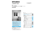
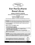
UVHB26 Series Gas Appliance
)
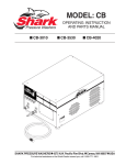
MANTEL
FPS1212
FP21214
BRASS TRIM (TOP)
BRASS TRIM
(BOTTOM)
HEARTH
BASE
3/4"
MOUNTING TABS
HEARTH
BASE
TOP VIEW
FP729
Fig. 1. UVHB26 Series specifications.
.~~:)
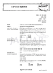
UVHB26 Series Gas Appliance
~I§§§I~
I
~I§§§
~
26.5
47.374
1
39.625
~
r=15375~
FP730
UVHB26 Series specifications
4
and dimensions.
-)
PYROMASTER@ UVHB26 Vent-Free Heaters
DESCRIPTION
The UVHB vent-free heaters is designed to be
installed into a FPS1212 or FPS1214 mantel
cabinet only. It may not be installed in any other
manner.
GAS SPECIFICATIONS
Model
Fuel
UVHB26RN Natural
The UVHB26 is available in Natural or Propane
gas, equipped with an oxygen depletion sensor
with a standing pilot.
Gas Control
Max.
Min.
Input
Input
B.T.U.H. B.T.U.H.
MillivoltsHi/lo
26,000
18.200
UVHB26RP Propane MillivoltsHi/lo
26,000
19,500
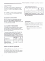
Fig. 2. Gas spectications.
MINIMUM CLEARANCES
Minimum clearance to combustibles are maintained when the UVHB26 is installed into the
FPS1212 or FPS1214 mantel cabinets. Top of unit
to ceiling minimum 42 inches.
.
'..,:,..'
'j/
GAS SUPPLY PRESSURES
PLANNING
Planning the installation is an important first step:
it will save time and money later in the actual
installation. In planning the installation, consider:
1. Where the heater will be located.
This heater must be isolated from the gas supply
piping system by closing its individual manual
shut-off valve during any pressure equal to or less
than 1/2 psig (3.45 kPa).
2. All components needed to complete the
project.
The heater and its individual shut-off valve must
be disconnected from the gas supply piping
system during any pressure testing of that system
at test pressures in excess of 1/2 psig (3.45 kPa).
NATURAL
LP
Inlet Minimum
4.5"W.e.
11"W.e.
Inlet Maximum
10.5" w.e.
13"W.e.
7.0"W.e.
11"W.e.
3.5"W.e.
10"W.e.
Input Adjustment
Manifold Pressure
Table
1. Gas supply pressures.
HIGH ELEVATION DERATING
Input ratings are shown in BTU per hour and are
for elevations up to 4,500 (1370m) feet.
For elevations above 4,500 (1370m) feet, ratings
should be reduced at the rate of four (4) percent
for each 1,000 feet above sea level.
'\
,.'
coo.'"
5
PYROMASTER@ UVHB26 Vent-Free Heaters
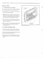
INSTAllATION
v
0 1. PREPARING THE UVHB26
, ,.,5)
.:')
To be sure that each step of the heater installation
is in order, use the check-off boxes provided.
The UVHB26 may only be used with the approved
mantel and hearth assembly.
1. After determining a location, open the mantel
hearth base carton and place into position on a
solid surface. NOTE: Be sure to level the base
before setting the UVHB26 heater in place.
, ,.,5)
r;?' '
2. Place the heater on the hearth base centering
side to side and 3/4" from the back edge of the
hearth base (See Fig. 1.)
3. Bend the lower mounting tabs down against the
hearth base and secure with two (2) wood
screws (See Fig. 1.)
r;?"
~~
BRASS TRIM
(SIDES)
FP731
Fig. 3. Insulating brass trim.
0 2. INSTALLING BRASS TRIM
1. Remove brass trim (3 pieces) from carton and
remove the protective coating from each piece.
..~.)
2. Using the provides (2) screws attached the side
pieces to the heater (See Fig.3.)
3. Mount the top trim to the heater and be sure to
overlap top trim to the front side of the side trim
pieces.
.
')
6
PYROMASTER@ UVHB26 Vent-Free Heaters
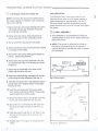
0
3.RUN GAS LINE FROM ITS SOURCE TO
THE HEATER
If gas piping from the source to the heater location has not been accomplished, install the
required pipe. Consult local plumbing code to
assure proper pipe size.
The gas pipeline can be brought in through the
right side of the heater.
NOTE: The gas line connection can be made with
properly tinned 3/8" copper tubing, 1/2" rigid pipe
or an approved flex connector, then reduced to
3/8" to the heater. Because some municipalities
have some additional local codes, it is always
best to consult your local authority. Consult the
current National Fuel Gas Code, ANSI Z223.1
A
Always check for gas leaks with a mild
soap and water solution. Do not use
an open flame for leak testing.
The gas control is equipped with a captured
screw type pressure test point, therefore it is not
necessary to provide a 1/8" test point up stream
of the control.
r
« ~)
1/2" GAS SUPPLY
c::to
, 1
r
r
1/2" NPTx 3/8"
1/2" FLEX
FLARELINE
SHUT-OFF VALVE
FP297 A
Fig. 4. Typical gas supply intallation..
7
PYROMASTER@
0
UVHB26 Vent-Free Heaters
4. OPTIONAL FK24 FAN HOOK-UP
NOTE: The FK24 fan should be installed before
the mantel cabinet is complete. Later installation
will be more difficult.
1. Remove the two (2) screws holding the screen
rods inside the bay top. Remove the screen
and rods then set aside.
2. Remove the bay top by removing three (3)
screws securing it to the combustion dome.
FAN OPERATION
The FK24 fan has a heat sensor that will not
allow the fan to come on until heater reaches a
preset temperature, approximately 100-120°F.
Once the heater reaches temperature use the
speed control knob to turn fan on and off to adjust
fan speed.
0
)
5. FINAL ASSEMBLY
1. Final assembly is accomplished by lifting the
mantel cabinet overtop of the heater behind the
brass trim pieces.
3. Tip out and lift the bay top and set aside.
2. NOTE: The mantel is designed to fit flush to
4. Remove three (3) nuts securing the fan bracket
to the back of the heater.
the wall as a freestanding unit. If desired, it
may be secured to the wall with nails or screws
(not provided).
5. Remove the (2) screws holding the bracket to
the fan. Discard this bracket.
7. Attach the fan assembly to the back of the
heater with the three (3) nuts.
8. Attach the electrical flag connectors to the fan
motor using the wire extension (See fig. 5.)
9. Feed the wire down the 1-inch diameter hole in
the left side of the radiant shield. Push plastic
bushing in hole.
10. Hook the wire extension to the wire leads
from the fan control box. NOTE: These leads
were hooked to the motor earlier.
TEMPERATURE
SENSOR,
CONTROL~
SPEED
~
~
r;.
.)
.
Extension
Wire
FP394A
Fig. 5. Wiring diagram.
/
HEXNUT
FANBRACKET
0
RADIANT
"",
SHIELD
..
11. Mount the thermo-disc to the shield under the
burner pan and secure with two (2) nuts.
-
,
(""'
/.
SCREWS
--
o!
0'
/
,0
,...
',.
V
l,:
.
FAN
. ': '
/,"
. .-/-4
':.;:;
'//~
BURNER
PAN
SHIELD
.
, /
12. Mount the fan on-off control to the base with
the studs provided and secure with two (2)
nuts.
13. Feed the plug through the 4" x 5" hole on the
left side of the heater and plug into a wall
receptacle.
~
AN
6. Remove the two (2) wires attached to the fan
and assemble the fan to the bracket as shown
in figure 6.
-:TO
RECEPT,o,C:"'O
THERMO
//.
...-
/
I
DISK
HEX NUT
'.
I
~~~~,
'1nEOSTAT
FP732
14. Repeat steps 1 through 3 to reassemble the
heater.
8
Fig. 6. Parts identification,
~",.I
)
PYROMASTER@ UVHB26 Vent-Free Heaters
A
WHEN INSTALLED, THE HEATER
MUST BEELECTRICALLY CONNECTED AND GROUNDED IN ACCORDANCE WITH LOCAL CODES
OR, IN THE ABSENCE OF LOCAL CODES:
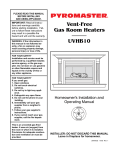
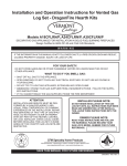
D 7. BOTTOM LOUVRE (GRILLE) REMOVAL
To remove the bottom louvre (grille), lift louvre up
and then out. See Figure 8.
U.S. INSTALLATIONS: FOLLOW LOCAL
CODES AND THE NATIONAL ELECTRICAL
CODE, ANSI/NFPA NO. 70.
VALVE
D
OPTIONAL
6. REMOTE WALL SWITCH (RN AND RP
MODELS ONLY)
1. Thread wire through the square hole located
on either side of unit. Do not cut wire or insulation on metal edges. Ensure that wire is protected. Run the other end to a conveniently
located wall receptacle box.
ON/OFF
SWITCH
FP382A
Fig. 7. Remote switch wiring.
=
2. Attach wire to switch and install switch into
receptacle box. Attach cover plate to switch.
"'J
',>,.J'/
3. Connect wiring
screws, remove
Install one lead
Install the other
A
to gas valve. Loosen the
jumper as shown in Fig 7.
from the wall switch to TH.
lead to TH/TP.
CAUTION: DO NOT WIRE MILLIVOLT REMOTE WALL SWITCH FOR
GAS HEATER TO A 120V POWER
SUPPLY. For lighting instructions, see
page 11.
"""'~
""', .~
RILLE
G
(LOUVRE)
"""
..
"""
'0'
""""
"""'~
""'.
"""" .~
"'01._..
~
""'1_'
"""'"
.."'.,,~
"""'"
""".",
T. ,.:; D
FP733
Fig. 8. Louvre installation and removal.
4. To turn the gas valve on, put the wall switch to
the 'ON' position.
9
PYROMASTER@ UVHB26 Vent-Free Heaters
~
D
~
LL
NOTCHES
LOG LOCATION
oil(
1. Set the back log on the studs attached to the
burner pan.
NOTCHES
TO LOCATE~
rtU
LOGS
~ ~~
F
2. Install the front log in-between the ember guard
and front lip of the unit. This should be a snug
fit.
3. Set the "Y"log in the notches in the front and
rear logs.
q/
REAR LOG
DIMPLES TO
LOCATE CROSS
LOGS
0
10. lOG INSTAllATION (refer to fig. 9)
:)
FOR "Y"
~
FRONT LOG
RIGHT LOG
LEFT
"Y" LOG
LOG ~REARLOG
FRONT LOG
FP734
4. Set the right cross log in the right notch of the
front log and the other end on the dimple of the
"Y" log.
5. Set the left cross log on the dimple of the "Y"
cross log and the opposite end in the groove in
the back of the front log.
D
Fig. 9. Log locations.
~"
<~:#
9. ROCK PLACEMENT
1. lava Rock
The lava rock provided with this heater must be
placed on the wire screen in the center of the
burner tube. Place just enough lava rock to cover
the screen. Do not pile the rock.
..
h
2. Volcanic rock
Spread the volcanic rock (gravel size)
on the burner pan of the fireplace. This
will give the fireplace a realistic look.
Under no circumstances should this lava rock
be placed on any part of the burner tube.
.,~)
10
PYROMASTER@ UVHB26 Vent-Free Heaters
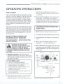
OPERATING INSTRUCTIONS
FIRST FIRING
Upon completing the gas line connection, a small
amount of air will be trapped in the line. When first
lighting the unit with pilot light, it will take a few
minutes to purge the trapped air. Once purging is
complete, the pilot and burner will light and operate as indicated in the instruction manual. Subsequent lightings of the appliance will not require
purging.
When lit for the first time, the appliance will emit a
slight odor for an hour or two. This is due to paint
and lubricants used in the manufacturing process.
After each lighting, vapor may condense and fog
the glass; this moisture disappears in a few minutes of burning.
repair it, call a qualified service technician.
Force or attempted repair may result in a fire
or explosion.
C. Do not use this appliance if any part has been
under water. Immediately call a qualified
service technician to inspect the appliance and
to replace any part of this control system and
any gas control which has been underwater.
LIGHTING INSTRUCTIONS FOR
HONEYWELL
1. STOP! Read the safety information above.
2. To access the controls, Remove lower louvre.
.
SAFETY PRECAUTIONS FOR
STANDING PilOT HEATERS
FOR YOUR SAFETY -
READ THIS SECTION
BEFORE LIGHTING!
A
WARNING: IF YOU DO NOT
FOllOW THESE INSTRUCTIONS
EXACTLY, A FIRE OR EXPLOSION MAY RESULT CAUSING PROPERTY
DAMAGE, PERSONAL INJURY OR lOSS
OF LIFE.
A. BEFORE LIGHTING smell all around the
appliance area for gas. Be sure to smell next to
floor because some gas is heavier than air and
will settle on the floor.
IF YOU SMELL
3. Turn wall switch and wireless remote OFF (if
used).
4. Push in gas control knob slightly and turn
clockwise ~
to OFF. See figure 10.
5. WAIT 5 MINUTES TO CLEAR OUT ANY GAS.
If you then smell gas, STOP! Follow A in the
safety information. If you do not smell gas, go
to next step.
BLACK
JUMPER
GAS:
1. Do not try to light any appliance.
2. Do not touch electrical switches; do not
use any phone in your building.
3. Immediately call your gas supplier from a
neighbor's phone. Follow your gas
supplier's instructions.
4. If you cannot reach your gas supplier, call
the fire department.
~
w>-,,~=
"~
HED
PILOT
B. Use only your hand to push in or turn the gas
valve control knob. Never use tools. If the
knob will not push in or turn by hand, don't try to
PIEZO IGNITOR
FP829
Fig. 10. Honeywell valve and pilot assembly.
11
PYROl'1ASTER@UVHB26 Vent-Free Heaters
6. Turn knob on gas control counterclockwise
~
to PilOT.
7. Push in control knob all the way and immediately light pilot depressing the piezo igniter
button at least once every second until a flame
appears. Continue to hold the control knob in
for about one (1) minute after the pilot is lit.
Release knob and it will pop back out. Pilot
should remain lit. If it goes out, repeat steps 4
through 7.
~)
. If the knob does not pop out when released, stop and call your service technician or gas supplier.
.
If the gas pilot will not stay lit after several
tries, turn the gas control knob OFF and
call your service technician or gas supplier.
8. After the pilot has been lit, the burner can be
turned on by turning knob counterclockwise
~
to the ON position. See figure 11.
9. Replace bottom louvre.
TO TURN OFF GAS TO APPLIANCE
,~~)
1. To access the controls, remove lower louvre.
2. Turn wall switch or wireless
remote (if used) to OFF.
3. Push in gas control knob
slightly and turn clockwise
~
to OFF. Do not force.
4. Install bottom louvre.
Fig. 11.
,.,)
12
PYROMASTER@ UVHB26 Vent-Free Heaters
MAINTENANCE
Keep the control compartment, logs and burner
area surrounding the logs clean by vacuuming or
brushing at least twice a year. THE LOGS CAN
GET VERY HOT - HANDLE ONLY WHEN
COOL.
Always turn off gas to the pilot before cleaning.
For relighting, refer to lighting instructions located
on the front cover plate.
Never obstruct the flow of combustion and ventilation air. Keep the front of the heater clear of all
obstacles and materials.
FP499A
Fig. 12. Proper pilot flame height.
Leave at least 36" clearance from front of heater
to combustibles.
CLEANING THE STANDING
PILOT CONTROL SYSTEM
The burner and control system consists of:
. main burner.
pilot burner
. gas orifice
. thermopile
. combination millivolt gas valve
Most of these components may require only an
occasional checkup and cleaning and some may
require adjustment. If repair is necessary, it
should be performed by a qualified technician.
In order to properly clean the burner and pilot
assembly, turn off the gas to the unit, remove the
logs exposing the burner and pilot assembly.
Clean all foreign materials from the top of the
burner. Check to make sure that burner parts are
clean. Visually inspect pilot. Brush or blow away
any dust or lint accumulation If pilot orifice is
plugged, disassembly may be required to remove
any foreign material from the orifice or tubing.
To obtain proper operation, it is imperative that
the pilot and burner's flame characteristics are
steady, not lifting or floating.
Typically, the top 1/8" of the thermopile should be
engulfed in the pilot flame. See Figure 12.
13
PYROMASTER@ UVHB26 Vent-Free Heaters
The air shutter is set at factory no adjustment
should be necessary.
"
)
....
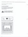
FLAME ADJUSTMENT
For units equipped with Hilla valves, flame adjustment is accomplished by rotating the Hilla adjustment knob located near the center of the gas
control. See Figure 13.
A
It is important to periodically perform
a visual check of the pilot and the
burner flames. See Figures 12 and 14.
Turn
clockwise
to increase
flame height.
~
Turn
counterclockwise
to lower
flame height.
<, : '~, ,
.
Fig. 13. Flame adjustment on Qas valve (standinQ pilot only).
~I~~~I~
- """i
"""""'"
"""~"""
:::::~::::::
"'" II"."
"'"
,"" """.
II,~,.
"'"
II,~'.
"",
"'~"
"'"
"", II,",
"""
::::I::::::
::::
:::'::::
"".,."'"
","
.."'"
,,~,'."",
""
,,~"
.~.'"",
...' ",'11'
:$:::'::::
...,."'"
...""""
..,.',II'"
' ,,'
'II" """
'II" ""'"
"'"
"",,
.."
"",'.
""
"'11,
""
'"II,
.." II,II.
,...""
.""~",,
:::::,,:::
..,.""'"
...,""'"
""'"
..."""..
......
.."
"""
"" 'II""
.."
"" '",,_,
'II""
.."
'11'."
.."
"'h'"""~"
~I~~~I~
FP;35
Fig. 14. Approximate
14
flame heights for each model.
)
'~;.;;;>
.
FP390A
.,)
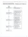
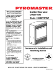
PYROMASTER@ UVHB26 Vent-free
Heaters
Uoneywell VS8421
TKOUBLESUOOTING.
START
CHECK
-NO
YES
SUPPLY LINE HOOKED UP
SHUTOFF VALVE OPEN
. LOCKOUT HAS ENGAGED. WAIT
~
PILOT LIGHTS WITH
PIElO IGNITOR
..
I-
NO
60 SECONDS AND TRY AGAIN.
.FORSPARKATELECTRODE
WHILE DEPRESSING PIElO
1/8" GAP TO PILOT HOOD
NEEDED.
ALL WIRING CONNECTIONS
REPLACE PIElO IGNITOR
..
YES
PILOT STAYS LIT
-NO-.
YES
..
..
.
.
FOR AIR IN THE LINES
THERMOPILE NEEDS A
MINIMUM 325mV. ADJUST
PILOT FLAME HEIGHT.
ALL WIRING CONNECTIONS.
REPLACE THERMOPILE
THERMOCOUPLE NEEDS A
MINIMUM OF 14mV.
DEFECTIVE VALVE. TURN TO
PILOT, METER SHOULD READ
GREATER THAN 100 mV. IF
NOT, REPLACE.
.
PilOT LIGHTSMAIN I-NO-.
BURNER
YES
VALVE IS TURNED ON
. WAll SWITCH IS NOT
TURNED ON. WATCH
FOR GROUNDED WIRES!
THERMOPilE NEEDS A
MINIMUM 325mV.
PLUGGED BURNER ORIFICE.
.
.
I SYSTEM lK:
15
PYROMASTER@
UVtfB26 Vent-Free Heaters
ACCESSORIES
')
The following accessories for these heaters are available from your local Pyromaster distributor. Each
accessory comes with a separate installation instruction for mounting to the particular heater. Be
sure to read each instruction thoroughly before installing.
ACCESSORIES - UVHB26
Accessory
ModelNumber
Description
Fan
Variable speed, heat-activated, kit
FK24
Remote Control
Wireless remote, batteries included
RM4
Wall switch
Wall switch kit
GWSK
CAUTION: This heater is a highly engineered system, and, as such, must be operated only with PYROMASTER approved components. If you use an unapproved
component to make any modifications, you may create a possible fire hazard and
will void the PYROMASTER warranty. In addition, such action may void the coverage provided by the owner's insurance.
~)
,,~,
,)
16
PYROMASTER@ UVHB26 Vent-Free Heaters
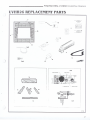
UVUB26
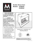
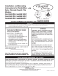
REPLACEMENT PARTS
7
~
-
~I~~~I~
=. =-.~
S
~
I~I
-if'>
18
-~
'.9
,..
,...,.."
...".
.,.".
==- 17
«::c> :>
4a
,,..."..
'"
"",'"
".
s::?------
"""..
".".'.
"""..
II"""...
..." ...
f'"
"!':~~:
10
~I~~
/",
14
12
<~ii/f:>
"~//
~~
~~
<:~~,.
11
d
13
~
'h~
.1
."",
~-=o-"--~
1>/~'\.16
:
15
6a1b
~.-=?~
2a1b
1a
~
\f. \:
'f1
~~)
3a/b
1b
"
-
.,,/
j
"
'
'-.----
'
FP736
17
PYROMASTER@ UVHB26 Vent-Free Heaters
REPLACEMENT PARTS - UVC SERIES
1.
Description
PARTNO.
Log - Assembly
3187169
1a. Log - Back
3187164
1b. Log - Front
3187165
1c. Log - Left
1d. Log - Right
1e. Log - "Y"
3187166
3187167
3187168
2a. Valve - NAT Honeywell
300000029
2b. Valve - LP Honeywell
3a. Pilot Assembly (NAT)
3b. Pilot Assembly (LP)
300000030
4a. Screen Assembly
Sa. Burner Tube Assembly (NAT)
.)
55464
55465
3187170
3187171
5b.' Burner Tube Assembly (LP)
6a. Orifice (NAT)
7535197
6b. Orifice (LP)
7. Top Trim
7535164
8.
Side Trim
3187130
9.
Volcanic Rock
7060151
10. Lava Rock
11. Fan
12. Louvre
3187132
)
.",,)
0055256
FK24
3187146
13. Electrical cord (6 ft)
14. Fan Temperature Sensor
51865
15. Speed Control
51738
16. Speed Control knob
51882
17. Remote Switch Kit
53875
18. Piezo Ignitor
""
51740
20000063
,,)
18
CFM Corporation
2695 Meadowvale Boulevard
Mississauga, Ontario L5N 8A3 Canada
(800) 668-5323
www.cfmcorp.com
PYROMASTER
®
UVHB10 Vent-Free Heaters
LIMITED 2/20 YEAR WARRANTY
For CFM Harris Systems Decorative Gas Appliances
The CFM Harris Systems extends the warranties specified
in paragraphs A and B below with respect to its Decorative
Gas Appliances (the “Gas Appliance”), including the CFM
Harris Systems supplied accessories and components
referred to in those paragraphs, subject to the following
conditions and limitations:
(1) These warranties are extended only to the Gas
Appliance installed in the continental United States,
including Alaska, and Canada; only if and so long as the
accordance with the installation and operating instructions
furnished therewith; and only if and so long as Gas
Appliance is not removed from its original installation.
(2). These warranties are limited to only the component
parts manufactured and supplied by CFM Harris Systems
The use of components manufactured by others with the
Gas Appliance (except for a listed Type B venting system
as defined in the installation instructions) could create
serious safety hazard, may result in the denial of certification by recognized national safety agencies, and could be
in violation of local building codes.
(3). The Gas Appliance must be operated at all times in
accordance with the operating instruction furnished
therewith. The Gas Appliance is designed to burn either
natural or propane gas only. Burning conventional
fireplace fuels such as wood, coal, or any other solid fuel
will cause damage to the Gas Appliance, will produce
excessive temperatures and will result in a fire hazard.
(4). These warranties are limited to repair, replacement
or furnishing a replacement for sale, as specified in
Paragraphs A and B, for a part found to CFM Harris
Systems’ satisfaction, after examination, to be defective in
materials or workmanship under normal conditions, use
and service.
(5). All obligations with respect to these warranties may
be fully discharged by CFM Harris Systems refunding the
wholesale price of a defective part.
(6). Except as otherwise expressly specified in Paragraphs A and B. NONE OF THESE WARRANTIES
COVER, AND CFM HARRIS SYSTEMS SHALL NOT BE
RESPONSIBLE FOR, ANY CONSTRUCTION, INSTALLATION, LABOR, TRANSPORTATION OR OTHER COSTS
OR EXPENSES ARISING FROM A DEFECTIVE PART,
ITS REPAIR OR REPLACEMENT OR OTHERWISE, NOR
SHALL CFM HARRIS SYSTEMS, INC. IN ANY EVENT BE
RESPONSIBLE FOR ANY INDIRECT, INCIDENTAL OR
CONSEQUENTIAL DAMAGES. EXCEPT TO THE
EXTENT PROVIDED BY LAW, THERE ARE NO IMPLIED
WARRANTIES WITH RESPECT TO THE GAS APPLIANCE, ITS COMPONENTS AND ACCESSORIES (IN-
20004232
CLUDING IMPLIED WARRANTIES OF MERCHANTABILITY OR FITNESS FOR A PARTICULAR PURPOSE), ALL
OF WHICH ARE HEREBY EXPRESSLY INCLUDED. IN
NO EVENT SHALL ANY IMPLIED WARRANTY PRESCRIBED BY LAW (NOTWITHSTANDING THE FOREGOING EXPRESS EXCLUSION) REMAIN IN EFFECT
AFTER EXPIRATIONS OF THE WARRANTIES SET
FORTH IN PARAGRAPHS A AND B.
A. Gas Appliances, electrical and manual components, glass panels, all sealants or adhesives and
optional accessories (exclusive of CFM Harris Systems
supplies decorative logs which are covered by a separate
warranty under paragraph B below):
Within two years from the date of manufacture of the gas
appliance, CFM Harris Systems will repair, or replace (at
our option) a defective part without charge.
B. Cement or ceramic fiber log components:
Within two years from the date of manufacture of the gas
appliance, CFM Harris Systems will replace a defective
part without charge. Within years three through twenty
from the date of manufacture of the gas appliance, CFM
Harris Systems will provide a replacement for a defective
part to the homeowner, but assumes no liability for
incurred labor cost.
The foregoing warranties gives you specific legal rights
and you may also have other rights which vary from state
to state. Some states do not allow limitations on how long
an implied warranty may last, so the limitation specified
above on the duration of any implied warranty prescribed
by law may not apply to you. Similarly, some states do not
permit the exclusion or limitation of incidental or consequential damages, so the above exclusion of such damages may not apply to you.
Since local building requirements may vary greatly throughout the country, users of CFM Harris Systems products
should determine in advance whether there are any building
code restrictions on the use of a specified product.
CFM HARRIS SYSTEMS MAKES NO REPRESENTATION OR WARRANTY REGARDING, AND SHALL NOT
BE RESPONSIBLE FOR, ANY BUILDING CODE COMPLIANCE.
13