1
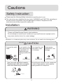
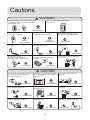
FLOOR UNIT
OPERATION MANUAL
HFU-09HA03(B)/R1
HFU-12HA03(B)/R1
HFU-09H03/R2(DB)
HFU-12H03/R2(DB)
HFU-18H03/R2(DB)
Please read this operation manual before using the air conditioner.
No.0010557172
Cautions
Disposal of the old air conditioner
Safety Instructions and Warnings
Before disposing an old air conditioner that
goes out of use, please make sure it's inoperative and safe. Unplug the air conditioner
in order to avoid the risk of child entrapment.
Before starting the air conditioner, read the
information given in the User's Guide carefully. The User's Guide contains very important observations relating to the assembly,
operation and maintenance of the air
conditioner.
It must be noticed that air conditioner system
contains refrigerants, which require specialized waste disposal. The valuable materials
contained in an air conditioner can be recycled
.Contact your local waste disposal center for
proper disposal of an old air conditioner and
contact your local authority or your dealer if
you have any question. Please ensure that
the pipework of your air conditioner does not
get damaged prior to being picked up by the
relevant waste disposal center, and contribute
to environmental awareness by insisting on an
appropriate, anti-pollution method of disposal.
The manufacturer does not accept responsibility for any damages that may arise due
to non-observation of the following
instruction.
Damaged air conditioners are not to be
put into operation. In case of doubt, consult
your supplier.
Use of the air conditioner is to be carried
out in strict compliance with the relative
instructions set forth in the User's Guide.
Installation shall be done by professional
people, don't install unit by yourself.
Disposal of the packaging of your
new air conditioner
For the purpose of the safety,the air conditioner must be properly grounded in accordance with specifications.
All the packaging materials employed in the
package of your new air conditioner may be
disposed without any danger to the
environment.
Always remember to unplug the air
conditioner before openning inlet grill. Never
unplug your air conditioner by pulling on
the power cord. Always grip plug firmly and
pull straight out from the outlet.
The cardboard box may be broken or cut into
smaller pieces and given to a waste paper
disposal service. The wrapping bag made of
polyethylene and the polyethylene foam pads
All electrical repairs must be carried out
by qualified electricians. Inadequate repairs
may result in a major source of danger for
the user of the air conditioner.
All these valuable materials may be taken to
a waste collecting center and used again after
adequate recycling.
Do not damage any parts of the air
conditioner that carry refrigerant by piercing
or performating the air conditioner's tubes
with sharp or pointed items, crushing or
twisting any tubes, or scraping the coatings
off the surfaces. If the refrigerant spurts
out and gets into eyes, it may result in
serious eye injuries.
Consult your local authorities for the name
and address of the waste materials collecting
centers and waste paper disposal services
nearest to your house.
1
Cautions
Do not obstruct or cover the ventilation
grille of the air conditoner.Do not put fingers
or any other things into the inlet/outlet and
swing louver.
Do not allow children to play with the air
conditioner.In no case should children be
allowed to sit on the outdoor unit.
The refrigerating circuit is leak-proof.
The machine is adaptive in following
situation
10.Please employ the proper power plug,
which fit into the power supply cord.
1.Applicable ambient temperature range:
Indoor
Cooling
11 .The power plug and connecting cable
must have acquired the local attestation.
o
Maximum:D.B/W.B 32 C/23 C
Minimum:D.B/W.B 18oC/14oC
12.In order to protect the units,please turn
off the A/C first, and at least 30 seconds
later, cutting off the power.
Maximum:D.B/W.B 43oC/26oC
Outdoor Maximum:D.B
18oC
27oC
15oC
Indoor
Maximum:D.B
Maximum:D.B
Outdoor
Maximum:D.B/W.B 24oC/18oC
Minimum:D.B/W.B -15oC
Heating
8. Young children should be supervised
to ensure that they do not play with
the appliance.
9. A breaker should be incorporated into
fixed wiring. The breaker should be
all-pole switch and the distance between
its two contacts should be not less than
3mm.
Specifications
o
7. The appliance is not intended for use
by young children or infirm persons
without supervision.
2. If the power supply cord is damaged, it
must be replaced by the manufacturer
or its service agent or a similar qualified
person.
3. If the fuse of indoor unit on PC board is
broken,please change it with the type of
T. 3.15A/ 250V. If the fuse of outdoor unit
is broken, change it with the type of
T.25A/250V.
4. The wiring method should be in line with
the local wiring standard.
5. After installation, the power plug should
be easily reached.
6. The waste battery should be disposed
properly.
2
Cautions
Safety Instruction
Please read the following Safety Instructions carefully prior to use
The instructions are classified into two levels, WARNING and CAUTION according to
the seriousness of possible risks and damages as follows. Compliance to the
instructions are strictly required for safety use.
Installation
WARNING
Please call Sales/Service Shop for the Installation.
Do not attempt to install the air conditioner by yourself because improper works
may cause electric shock, fire, water leakage.
Installation in a inadequate place may cause accidents. Do not install in the following place.
securely
Connect the earth
cable.
CAUTION
Do not install in the
place where there is
any possibility of
inflammable gas
leakage around the
unit.
earthing
Do not get the unit
exposed to vapor
or oil steam.
PROHIBITION
Use fuse with specified capacity.
Replacement with steel or copper
wires are absolutely prohibited.
PROHIBITION
Check proper
installation of the
drainage
STRICT
ENFORCEMENT
Grounding wire should not be connected
to that of gas pipeline, water pipeline,
lighting arrester or telephone.
FUSE
COPPERWIRE
STEEL WIRE
3
Cautions
WARNING
When abnormality such as burnt-small found,
immediately stop the operation button and
contact sales shop.
Use an exclusive power source with a
circuit breaker
STRICT
ENFORCEMENT
OFF
Connect power supply cord
to the outlet completely
STRICT
ENFORCEMENT
Do not use power supply cord
in a bundle.
After installed, the unit shall be
tested for electric leakage.
STRICT
ENFORCEMENT
Take care not to damage
the power supply cord.
PROHIBITION
Do not insert objects into the air
inlet or outlet.
PROHIBITION
PROHIBITION
PROHIBITION
Do not start or stop the
operation by disconnecting
the power supply cord and so on.
Do not use power supply cord
extended or connected in halfway
Do not channel the air flow directly
at people, especially at infants or
the aged.
Do not try to repair or reconstruct
by yourself.
PROHIBITION
PROHIBITION
CAUTION
Do not use for the purpose of storage of Take fresh air occasionally especially Do not operate the switch with
food, art work, precise equipment,
when gas appliance is running at the wet hand.
breeding, or cultivation.
same time.
STRICT
ENFORCEMENT
PROHIBITION
Do not install the unit near a fireplace
or other heating apparatus.
Check good condition of the
installation stand
PROHIBITION
Do not place animals or plants in
the direct path of the air flow
PROHIBITION
Do not pour water onto the unit
for cleaning
PROHIBITION
PROHIBITION
Do not place any objects on or
climb on the unit.
PROHIBITION
PROHIBITION
4
Do not place flower vase or water
containers on the top of the unit.
PROHIBITION
Parts and Functions
Indoor unit
1.OUTLET
2.CONTROL PANEL
3.INLET
4.FILTER (inside)
5.OUTLET
Outdoor unit
HFU-09HA03(B)/R1
HFU-12HA03(B)/R1
HFU-09H03/R2(DB)
HFU-12H03/R2(DB)
HFU-18H03/R2(DB)
OUTLET
CONNECTING PIPING AND ELECTRICAL WIRING
INLET
DRAIN HOSE
5
Parts and Functions
CAUTION
Before opening the front grille, be sure
to stop the operation and turn the
breaker OFF.
Do not touch the metal parts on the
inside of the indoor unit, as it may result
in injury.
Receiver
Signals are received from the remote
controller here.
Upon receiving a signal, there is a receiving
sound.
Air outlet selection switch
This setting blows air from upper outlet only.
This setting automatically decides a blow
pattern depending on mode and conditions.
This setting is
recommended.
The unit is shipped from the
factory with this setting.
ON/OFF button
Push once to start operation,
push once again to stop it.
Operation is set to AUTO, air
flow is set to AUTO FAN.
Use when remote controller is
not available.
Air outlet
selection
Indoor temperature sensor
Senses the air temperature around the unit.
Air flow selection
Operating
mode
Make air flow selection according to what suits you.
When setting the air flow selection
switch to
Cool
mode
Air conditioner automatically decides the
appropriate blowing pattern depending on the
operating mode/situation.
During Dry mode, so that cold air does not come
into direct contact with people, air is blown upper
air outlet.
Situation
When the room has
become fully cool, or
when one hour has
passed since turning
on the air conditioner.
At start of operation
or other times when
the room is not fully
cooled.
At times other than
below. (Normal
time.)
When setting the air outlet selection
switch to
Blowing pattern
So that air does not come
into direct contact with
people, air is blown upper air
outlet, room temperature is
equalised
Air is blown from the upper and
lower air outlets for high speed
cooling during Cool mode, and
for filling the room with warm
air during Heat mode.
Heat
mode
Regardless of the operating mode or situation, air
blows from the upper air outlet.
Use this switch when you do not want air coming
out of the lower air outlet. (While sleeping etc..)
At start or when air
temperature is low.
6
So that air does not come into
direct contact with people. Air
is blown upper air outlet.
Parts and Functions
Remote Controller
4. MODE
Used to select AUTO, COOL, DRY, FAN and
HEAT operation.
5. ON/OFF
Used for unit start and stop.
6. SWING
Used to adjust the up/down air flow direction.
7. TEMP.
Used to select your desired temperature.
8. TIMER ON display
9. SLEEP display
10. FAN SPEED display
Remote controller:
LOW
MED
HI
11. SWING UP/DOWN display
12. MODE display
Operation
mode
AUTO
Remote
controller
AUTO
COOL
DRY
FAN
HEAT
1.TIMER
Used to select TIMER ON,
TIMER OFF, TIMER ON-OFF
2.HOUR
Used to set clock and timer setting.
3.CLOCK
Used to set correct time.
Note:
1. The following functions and related
displays are not available for all models:
Display of humidifying and atmosphere
humidity.
2. There is health display with the remote
controller in this type, but without health
function.
13. SIGNAL SENDING display
14. TEMP. display
Remote controller: to display the TEMP. setting.
15. CLOCK display
16. TIMER OFF display
17. FAN
Used to select fan speed: LO,MED,HI,AUTO
18. SET
Used to confirm timer and clock settings.
19. SLEEP
Used to select sleep mode.
20. RESET
When the remote controller appears abnormal,
use a sharp pointed item to press this button
to reset the remote controller to normal condition.
21. LOCK
Used to lock buttons and LCD display. If
pressed, the other buttons will be disabled and
the lock condition display appears.
Press it once again, lock will be canceled and
lock condition display disappears.
22. LOCK display
23. POWER/SOFT
7
Parts and Functions
Clock Set
When unit is started for the first time and after replacing batteries in remote
controller, clock should be adjusted as follows:
1. Press CLOCK button,"AM" or "PM" flashes.
2. Press or
to set correct time. Each press will increase or decrease 1
min. If the button is kept depressed, time will change quickly.
3. After time setting is confirmed, press SET, "AM" or "PM" stop
flashing,
while clock starts working.
Remote controller's operation
When in use, put the signal transmission head directly to the receiver hole on the indoor unit.
The distance between the signal transmission head and the receiver hole should be within 7 m
without any obstacle as well.
Don't throw or knock the remoter controller.
When electronic-started type fluorescent lamp or change-over type fluorescent lamp or wireless
telephone is installed in the room, the receiver is apt to be disturbed in receiving the signals,
so the distance to the indoor unit should be shorter.
Loading of the battery
Load the batteries as illustrated right
2 R-03 (7#) batteries
Remove the battery cover:
Slightly press" "area and push down the cover
as illustrated.
Load the battery:
Be sure that the loading is in line with the "+" / "-".
request as illustrated on the bottom of the case.
Put on the cover again.
Confirmation indicator:
After pressing power ON/OFF, if no display, reload the batteries.
Note:
Full display or unclear display during operation indicates the batteries have been used up.
Please change batteries.
Used two new same-typed batteries when loading.
If the remote controller can't run normally during operation, please remove the batteries and
reload several minutes later.
Hint:
Remove the batteries in case unit won't be in usage for a long period. If there are any display after
taking-out, just need to press reset key.
8
Operation
Auto Operation
Remote controller
1. Unit start
Press ON/OFF on the indoor unit, or press ON/OFFon
the remote controller, unit starts.
Previous operation status appears on LCD display (no
timer and sleep), and set the operation mode.
2.Select operation mode
Press MODE button. For each press, operation mode
changes as follows:
Remote controller:
AUTO
COOL
DRY
FAN
HEAT
Then Select Auto operation
3.Select temp.setting
5
4
Press TEMP. button
Every time the button is pressed, temp.setting
o
increase 1 C,if kept depressed, it will increase
rapidly
Every time the button is pressed, temp.setting
o
decrease 1 C,if kept depressed, it will decrease
rapidly
Select a desired temperature.
4.Fan speed selection
Press FAN button. For each press, fan speed changes as
follows:
Remote controller:
LOW
MED
HI
AUTO
Air conditioner is running under displayed wind speed
When FAN is set to AUTO, the air conditioner
automatically adjusts the fan speed according to room
temperature.
5.Unit stop
Press ON/OFF button, the unit stops.
About AUTO mode
In AUTO run mode, the air conditioner will
automatically select cooling or heating
operation mode according to room temperature.
9
Operation
Cool Operation
1. Unit start
Remote controller
Press ON/OFF on the indoor unit, or press ON/OFFon
the remote controller, unit starts.
Previous operation status appears on LCD display (no
timer and sleep).
2.Select operation mode
Press MODE button. For each press, operation mode
changes as follows:
Remote controller:
AUTO
COOL
DRY
FAN
HEAT
Then Select Cool operation
3.Select temp.setting
Press TEMP. button
Every time the button is pressed, temp.setting
o
increase 1 C,if kept depressed, it will increase
rapidly
Every time the button is pressed, temp.setting
o
decrease 1 C,if kept depressed, it will decrease
rapidly
Select a desired temperature.
4.Fan speed selection
Press FAN button. For each press, fan speed changes as
follows:
Remote controller:
LOW
MED
HI
AUTO
Air conditioner is running under displayed wind speed
When FAN is set to AUTO, the air conditioner
automatically adjusts the fan speed according to room
temperature.
5.Unit stop
Press ON/OFF button, the unit stops.
10
Operation
DRY Operation
1. Unit start
Press ON/OFF on the indoor unit, or press ON/OFFon
the remote controller, unit starts.
Previous operation status appears on LCD display (no
timer and sleep).
Remote controller
2.Select operation mode
Press MODE button. For each press, operation mode
changes as follows:
Remote controller:
AUTO
COOL
DRY
FAN
HEAT
Then Select DRY operation
3.Select temp.setting
Press TEMP. button
Every time the button is pressed, temp.setting
o
increase 1 C,if kept depressed, it will increase
rapidly
Every time the button is pressed, temp.setting
o
decrease 1 C,if kept depressed, it will decrease
rapidly
Select a desired temperature.
4.Fan speed selection
Press FAN button. For each press, fan speed changes as
follows:
Remote controller:
LOW
MED
HI
AUTO
Air conditioner is running under displayed fan speed.
In DRY mode, when room temperature becomes
lower than temp.setting+2oC,unit will run intermittently
at LOW speed regardless of FAN setting.
COOL operation starts when room
temp.is higher than temp.setting.
5.Unit stop
Ultra-low air flow
Press ON/OFF button, the unit stops.
Temp.setting+2oC
Temp.setting
On reaching temp.setting +2oC
unit will run in mild DRY mode.
11
Operation
FAN Operation
1. Unit start
Remote controller
Press ON/OFF on the indoor unit, or press ON/OFFon
the remote controller, unit starts.
Previous operation status appears on LCD display (no
timer and sleep).
2.Select operation mode
Press MODE button. For each press, operation mode
changes as follows:
Remote controller:
AUTO
COOL
DRY
FAN
HEAT
Then Select FAN operation
3.Fan speed selection
Press FAN button. For each press, fan speed changes as
follows:
Remote controller:
LOW
MED
HI
4.Unit stop
Press ON/OFF button, the unit stops.
About FAN operation
In FAN operation mode, the unit will not operate in
COOL or HEAT mode but only in FAN mode. AUTO is
not available in FAN mode. And temp. setting is disabled.
In FAN mode, SLEEP operation is not available.
12
Operation
HEAT Operation
Remote controller
1. Unit start
Press ON/OFF on the indoor unit, or press ON/OFFon
the remote controller, unit starts.
Previous operation status appears on LCD display (no
timer and sleep).
2.Select operation mode
Press MODE button. For each press, operation mode
changes as follows:
Remote controller:
AUTO
COOL
DRY
FAN
HEAT
Then Select HEAT operation
3.Select temp.setting
Press TEMP. button
Every time the button is pressed, temp.setting
o
increase 1 C,if kept depressed, it will increase
rapidly
Every time the button is pressed, temp.setting
o
decrease 1 C,if kept depressed, it will decrease
rapidly
Select a desired temperature.
4.Fan speed selection
Press FAN button. For each press, fan speed changes as
follows:
Remote controller:
LOW
Regarding the ambient
temperature display during
the heating operation
In defrosting,the indoor temperature
value displayed may be reduced due
to the dropping of cooling air of the
evaporator of indoor unit under cooling
mode. It is normal phenomenon.
MED
HI
AUTO
Air conditioner is running under displayed wind speed
IN HEAT mode, warm air will blow out after a short period
of the time due to cold-draft prevention function.
When FAN is set to AUTO, the air conditioner
automatically adjusts the fan speed according to room
temperature.
5.Unit stop
Press ON/OFF button, the unit stops.
13
Operation
Adjusting the Air Flow Direction
You can adjust the air flow direction to increase
your comfort
Notes on flap angles
When SWING is selected, the flap swinging range depends
on the operation mode.(See the figure.)
Adjusting the flap
COOL/DRY
HEAT
NOTE
Unless [SWING] is selected, you should set the flap at a
near-horizontal angle in HEAT mode and at a upward
position in COOL or DRY mode to obtain the best
performance.
CAUTION
Do not try to adjust the flap by hand.
When adjusting by hand, the mechanism may not
operate properly or condensation may drip from air
outlets
ATTENTION
When adjusting the flap by hand, turn off the unit,
and use the remote controller to restart the unit.
Adjusting the louver
Hold the knob and move the louver.
(You will find a knob on the left-side and the right-side blades
ATTENTION
Be careful when adjusting the louver. Inside the air
outlet, a fan is rotating at a high speed.
14
Operation
SLEEP Operation
Before going to bed , you can simply press the
2. In HEAT mode
SLEEP button and unit will operation in SLEEP
3 hours after SLEEP
mode starts, temperature
o
mode and bring you a sound sleep.
will become 1 C lower than temperature setting.
After
another 3 hours temperature decrease by
Use of SLEEP function
o
1 C further. The unit will run for further 2 hours
After the unit starts, set the operation status,
then stops. Temperature is lower than
then press SLEEP button before which the
temperature setting so that room temperature
clock must be adjusted and time being set.
won't be too high for your sleep.
Operation Mode
1. In COOL,DRY mode
Temperature setting
Unit stop
3 hours after SLEEP
mode starts, temperature
o
will become 1 C higher than temperature setting.
o
3 hr
Decreases 1 C
After another 3 hours temperature rises by 1 C
further. The unit will run for further 2 hours then
3 hr
Decreases 1 C
stops. Temperature is higher than temperature
setting so that room temperature won't be too
low for your sleep.
Approx. 2 hrs
o
o
SLEEP
operation starts
Remote controller
SLEEP
operation stops
In HEAT mode
3. In AUTO mode
The unit operates in corresponding sleep
SLEEP mode adapted to the automatically
selected operation mode.
4. In FAN mode
It has timing off function.
5. The sleep time can be adjusted within
the range of 1-8 hours.
Push the SLEEP button. The remote
controller will display " ", and display the
timing off and detail off time in the timing
off setting area.
Push the time adjusting button to adjust the
detail sleep time.
6. If the sleep time in cooling, dehumidifying
and heating run is less than 8 hours
SLEEP operation starts
Within the set sleep time, the conditioner will
run as per the procedure described in 1 and
2. It will be switched off automatically when
the sleep time is expired.
SLEEP operation stops
Approx. 2 hrs
o
Rises 1 C
3 hr
o
3 hr
Rises 1 C
Temperature setting
Unit stop
In COOL,DRY mode
15
Operation
Timer On/Off Operation
Set clock correctly before starting TIMER operation.
Remote controller
1. After unit starts, select your desired operation mode.
Operation mode will be displayed on LCD
2. Timer mode selection
Press TMIER button to change TIMER mode. Every time'
the button pressed, display changes as follows:
Remote controller:
BLANK
TIMER ON
TIMER OFF
TIMER ON-OFF
Then select your desired TIMER mode (TIMER ON or
TIMER OFF). "
"or "
"will flash.
3.Time setting
Press HOUR
button.
Every time the button is pressed, time setting
increases 1 min, if kept depressed, it will increase
rapidly.
Every time the button is pressed, time setting
decreases 1 min, if kept depressed, it will decrease
rapidly.
It can be adjusted within 24 hours.
4.Confirming your setting
After setting correct time, press SET button to confirm
"
"or"
"on the remote controller stops flashing.
Time displayed: Unit starts or stops at x hour x min.
(TIMER ON or TIMER OFF).
5.Cancel TIMER mode
Just press TIMER button several times until TIMER
mode disappears.
Hints:
After replacing batteries or a power failure happens, time setting should be reset.
Remote controller possesses memory function, when use TIMER mode next time,just
press SET button after mode selecting if time setting is the same as previous one.
16
Operation
TIMER On-Off Operation
Remote Controller
Set clock correctly before starting TIMER operation.
1. After unit starts, select your desired operation mode
Operation mode will be displayed on LCD.
2. Timer mode selection
Press TIMER button to change TIMER mode. Every time
the button is pressed, display changes as follows:
Remote controller:
BLANK
TIMER ON
TIMER OFF
TIMER ON-OFF
Then select your desired TIMER mode (TIMER ON - OFF).
"
"will flash.
3.Time setting
Press HOUR
button.
Every time the button is pressed, time setting
increases 1 min, if kept depressed, it will increase rapidly.
Every time the button is pressed, time setting
decreases 1 min, if kept depressed, it will decrease rapidlly.
It can be adjusted within 24 hours.
4.Timer confirming for TIMER ON
After setting correct time, press TIMER button to confirm
"
" on the remote controller stops flashing.
"
" starts flashing.
Time displayed: Unit starts or stops at x hour x min.
5.Time setting for TIMER OFF
Just press HOUR button ,follow the same procedure in
"Time setting for TIMER ON"
6.Time confirming for TIMER OFF
After time setting,press SET button to confirm.
"
" on the remote controller stops blinking.
Time displayed:Unit stops at x hour x min.
To cancel TIMER mode
Just press TIMER button several times until TIMER
mode disappears.
According to the Time setting sequence of TIMER ON
or TIMER OFF, either Start-Stop or Stop-Start can be
achieved.
17
Operation
POWER/SOFT Operation
POWER Operation
When you need rapid heating or cooling, you can use this funciton.
Selecting of POWER operation
Press POWER/SOFT button. Every time the button is pressed,display
changes as follows:
BLANK
SOFT
POWER
Stop the display at
In POWER operation status:
In HEAT or COOL mode, fan speed automatically runs in HI mode
for 15 min then returns to original status setting.
To cancel POWER operation
Press POWER/SOFT button twice ,POWER/SOFT disappears.
SOFT Operation
You can use this function when silence is needed for rest or reading.
Selecting of SOFT operation
Press POWER/SOFT button. Every time the button is pressed,display
changes as follows:
BLANK
POWER
SOFT
Stop the display at
In SOFT operation mode, fan speed automatically takes"LOW"
To cancel SOFT operation
Press POWER/SOFT button twice ,POWER/SOFT disappears.
Hints:
During POWER operation, in rapid HEAT or COOL mode, the room
will show inhomogeneous temperature distribution.
Long period SOFT operation will cause effect of not too cool
or not too warm.
18
Operation
EMERGENCY OPERATION AND TEST OPERATION
EMERGENCY OPERATION
Carry out this operation only when the remote
controller is defective or lost.
POWER
TIMER
RUN
Unit start
When the emergency operation switch is
pressed, a sound you can hear, which
means the start of this operation.
ON/OFF
Follow the requirements below.
EMERGENCY SWITCH
Room
Designated Timer Air flow Operation
Anion
temperature temperature mode speed
mode
>23oC
26oC
None
AUTO
COOL
None
23oC
23oC
None
AUTO
HEAT
None
*
Unit stop (to cancel emergency operation)
Press the emergency switch and hear a sound, the unit stops.
TEST OPERATION
Use this switch in the test operation when the room
temperature is less 16oC, do not it in the normal
operation.
Unit start
POWER
Continue to press the test operation switch
for more than 5 seconds. After you hear the
"BI" sound twice, release your finger from
the switch, the test operation starts and the
air conditioner starts with the air flow speed
setting "Hi".
TIMER
RUN
ON/OFF
TEST SWITCH
Unit stop(to cancel test operation)
Push the test run switch or operate with remote controller to cancel the test run.
If you use the remote controller to cancel the test run, the conditioner will then run as
per the working mode displayed on the remote controller.
19
Operation hints
Remote monitoring
The control board of the indoor unit reserves the communication port for remote control. If
you install the peripheral equipment according to the manual of the matching remote control
detector, it can realize the computer management or remote monitoring of the conditioner.
Please refer to the manual of the " Conditioner remote control detector" for the details
Power failure resume(please set and apply as necessary)
With setting of power failure resume, if sudden power failure occurs, the unit will resume
original operation when power is supplied again.
Setting method
With ON of remote controller (except TIMER and FAN),repeatedly press SLEEP button 10
times in 5 seconds, after 4 Beep from the buzzer, the unit comes into power failure resume
mode.
To cancel:
press SLEEP button continuously 10 times in 5 seconds, the buzzer sounds Beep twice and
power failure resume function is canceled.
Note:
When sudden power failure happens during unit operation in power failure resume mode,if
the air conditioner is not desired for use in a long period, please shut off the power supply
in case that the unit automatially resume operation when power is re-supplied, or press
ON/OFF to turn off the unit when power resumes.
20
Maintenance
Cleaning of the unit
Turn off the power switch
Do not touch with wet hand
Take off the air inlet grill
First switch off the power supply, take off the
screw cap, loosen the screw with cross screwdriver.
Clean the filter
Use water or vacuum cleaner to remove
dust. If it is too dirt, clean with detergent or
neutral soap water.
Rinsing with fresh water, dry the filter and
re-assemble.
Caution:
o
Do not wash filter in hot water above 40 C,
which will damage the filter.
Do carefully wipe the filter.
Clean the indoor(outdoor) unit
Clean with warm cloth or neutral detergent,
then wipe away moisture with dry cloth. Do
o
not use too hot water(above 40 C), which will
cause discoloration or deformation. Do not
use pesticide or other chemical detergents.
21
Do not clean with hot
water or solvent
Maintenance
Maintenance at the end of application season
On a fine day, unit shall be started and operate in
FAN mode for about half a day unit the inside of
the unit becomes thoroughly dry.
Turn off the unit operation switch and power on/off.
Otherwise, there will be some electricity consumption
even the unit is in stop status.
Clean the filter and indoor, outdoor unit, cover
the units well.
Maintenance before beginning of application season
Check there are no obstacles in the air inlet and
outlet to avoid impairing of working efficiency.
Please do attach the air filter to ensure the
electrostatic filters not soiled. Otherwise,dirt
will come into and damage the unit or bring
failures.
22
Trouble shooting
Before asking for service, check the following first.
Phenomenon
Cause or check points
The system does not restart
immediately.
When unit is stopped, it won't restart
immediately until 3 minutes have elapsed
to protect the system.
When the electric plug is pulled out and
reinserted, the protection circuit will work
for 3 minutes to protect the air conditioner.
Noise is heard:
Normal
Performance
inspection
Smells are generated.
Mist or steam are blown out.
Multiple
check
Does not work at all.
Poor cooling
During unit operation or at stop, a swishing
or gurgling noise may be heard. At first 2-3
minutes after unit start, this noise is more
noticeable. (This noise is generated by
refrigerant flowing in the system.)
During unit operation, a cracking noise may
be heard. This noise is generated by the
casing expanding or shrinking because of
temperature changes.
Should there be a big noise from air flow in
unit operation, air filter may be too dirty.
This is because the system circulates smells
from the interior air such as the smell of
furniture, cigarettes.
During COOL or DRY operation, indoor unit
may blow out mist. This is due to the sudden
cooling of indoor air.
Is power plug inserted?
Is there a power failure?
Is fuse blown out?
Is the air filter dirty? Normally it should be
cleaned every 15 days.
Are there any obstacles before inlet and outlet?
Is temperature set correctly?
Are there some doors or windows left open?
Is there any direct sunlight through the
window during the cooling operation?(Use
curtain)
Are there too much heat sources or too many
people in the room during cooling operation?
23
Installation Manual of Room Air Conditioner
more than 10 cm
Installation of indoor unit
mo
re
t
ha
n1
0c
m
m
00
n1
re
mo
tha
cm
Figure.1
Figure.2
or
e
th
an
10
cm
selection of installation place
Place where it is easy to route drainage pipe
and outdoor piping.
Place, away from heat source and with less
direct sunlight.
Place where cool and warm air could be
delivered evently to every corner of the room.
Place near power supply socket.Leave enough
space around the unit.
Place, robust not causing vibration, where the
body can be supported sufficiently.
To prevent interference, place it at least 1m
away from other electric machines, such as
TV set, radio.
Installation
According to the dimension of the Figure 2 shown
nail two cement steel nails on the wall keep 2-3mm
out, then hang the back of the unit on them.
There must be no gap between the indoor unit and
wall.
Remove the front panel,then use two fastening
screws to fix the unit on the floor. As Figure 3 shown.
Once refrigerant piping and drain piping connections
are complete,fill the gap of the through hole with putty.
Attach the front panel and front grille in their orginal
positions once all connections are complete.
Figure.3
tha
re
mo
Installation of outdoor unit
selection of installation place
mo
re
th a
Place strong enough to support the unit and will
n1
0c
m
not cause vibration and noise.
Place where discharged wind and noise does not
cause a nuisance to the neighbors.
Place where is less affected by rain or direct sunlight
and is sufficiently ventilated,or to install a shield.
Place with enough space for smooth air flow.
re
mo
tha
n1
0c
m
mo
re
n6
0c
m
Figure.4
24
tha
n1
0c
m
Installation Manual of Room Air Conditioner
Tool necessary
No.
Shape and description
1.Screw driver
2.Hacksaw
3.70mm dia. hole core drill
4.Spanner(dia.17,27mm)
5.Spanner(14,17,27mm)
6.Pipe cutter
7.Flaring tool
8.Knife
9.Nipper
10.Gas leakage detector
or soap water
11.Measuring tape
12.Reamer
13.Refrigerant oil
QTY
Remote controller
1
Drain hose
1
Plastic cap
4
Drain-elbow
1
Self-tapping screw
4
Rubber pad
4
dry battery #7
2
Floor fixing dimensions of the outdoor unit(Unit:mm)
Standard accessories
256
Following parts shall be field
supplied
140
Mark
500
140
HFU-09H03/R2(DB)
HFU-12H03/R2(DB)
HFU-18H03/R2(DB)
Part name
Adhensive tape
B
Pipe clip
310
A
C
Connecting hose
D
Insulation material
E
Drain hose
500
105
550
HFU-09HA03(B)/R1
105
310
105
HFU-12HA03(B)/R1
105
Fixing of the unit
1. Position of the wall hole
Wall hole should be decided according to installation
place and piping direction.(refer to installation drawings).
Indoor side
Wall hole
Outdoor side
Thickness
of wall
2. Making a wall hole
Drill a hole of 120x70mm dia. with a little slope towards
outside.
25
(Cross section of wall hole)
Installation Manual of Room Air Conditioner
3. Piping connection
Connecting method
Apply refrigerant oil at half union and flare nut.
To bent a pipe, give the roundness as large as possible not to crash the pipe.
When connecting pipe, hold the pipe center to center then screw nut on by hand, refer to Fig.
Be careful not to let foreign matters, such as sands enter the pipe.
Forced fastening without careful
centering may damage the
threads and cause a leakage of gas.
Pipe Diameter
Fastening torque
Liquid side 6.35mm(1/4")
18N.m
Gas side 9.52mm(3/8")
42N.m
Gas side 12.7mm(1/2")
55N.m
Piping connection of the indoor unit
1. Arrangement of piping and drainage pipe
Remove the cover before working.
Cut away, with a hammer or a saw, the lid for piping according to piping direction.
insulation material
Drain hose
Copper tube
Connecting electric cable for
indoor and outdoor unit
According to the piping method, connect the piping on indoor unit with union of connection pipe.
Arrange the piping as per the wall hole and bind drain hose connecting electric cable and piping
together with polyethylene tape.
Insert the bound piping connecting electric cable and drain hose through wall hole to connect
with outdoor unit.
2. Arrangement drain hose
Drain hose shall be placed in under place.
There should be a slope when arrange drain hose. Avoid up and down waves in drain hose.
If humidity is high, drain pipe(especially in room and indoor unit) must be covered with
installation material.
26
Installation Manual of Room Air Conditioner
3. Piping connection of the outdoor unit
Connecting the connecting pipe and inlet and
outlet liquid pipe according to the piping method
Liquid Side
6.35mm(1/4")
Purging Method:(For R410A)
Detach the service port's cap of 3-way valve, the
valve rod's cap for 2-way valve and 3-way's, connect
the service port into the projection of charge hose
(low) for gaugemanifold. Then connect the projection
of charge hose (center) for gaugemanifold into
vacuum pump.
Gas Side
9.52mm(3/8")
12.7mm(1/2")
3-way valve
2-way valve
Gaugemanifold(for R410A)
Anti countercurrent joint
Vacuum pump(for R410A)
Tube(for R410A)
Open the handle at low in gaugemanifold, operate
vacuum pump. If the scale-moves of gause (low)
reach vacuum condition in a moment, check
again.
Open
Vacuumize for over 15min. And check the level gauge
which should read -0.1 MPa (-76 cm Hg) at low
pressure side. After the completion of vacuumizing,
close the handle 'Lo' in gaugemanifold and stop the
operation of the vacuum pump.
Check the condition of the scale and hold it for 1-2min.
If the scale-moves back in spite of tightening, make
flaring work again, the return to the beginning of
.
Close
Open the valve rod for the 2-way valve to an angle of
anticlockwise 90 degrees.
After 6 seconds, close the 2-way valve and make
the inspection of gas leakage.
No gas leakage?
3-way valve
2-way valve
Open
90o
Service port
90ofor 6 sec.
If it does not stop gas leakage, discharge
whole refrigerants from the service port.
After flaring work again and vacuumize,
fill up prescribed refrigerant from the gas
cylinder
In case of gas leakage, tighten
parts of pipe connection. If
leakage stops, then proceed
steps.
Detach the charge hose from the service port, open
2-way valve and 3-way. Turn the valve rod anticlockwise
until hitting lightly.
2-way valve
Liquid Side
3-way valve
6.35mm(1/4")
2-way valve
To prevent the gas leakage, turn the service port's
cap, the valve rod's cap for 2-way valve and 3-way's
a little more than the point where the torque increases
suddenly.
2-way valve
3-way valve
Gas Side
9.52mm(3/8")
12.7mm(1/2")
3-way valve
HFU-09H03/R2(DB)
HFU-12H03/R2(DB)
HFU-18H03/R2(DB)
Valve rod cap
Service port cap
After attaching the each caps, check the gas leakage
around the caps.
CAUTION:
1.If the refrigerant of the air conditioner leaks, it is necessary to
discharge all the refrigerant. Vacuumize first, then charge the liquid
refrigerant into air conditioner according to the amount marked on
the name plate.
27
Valve rod cap
2.Please do not let other cooling medium, except specified one (R410A),
or air enter into the cooling circulation system. Otherwise, there will be
abnormal high pressure in the system to make it crack and lead to
personal injuries.
Installation Manual of Room Air Conditioner
3. Piping connection of the outdoor unit
Connecting the connecting pipe and inlet and
outlet liquid pipe according to the piping method
3-way valve
Purging Method:(For R407C)
2-way valve
Detach the service port's cap of 3-way valve, the
valve rod's cap for 2-way valve and 3-way's, connect
the service port into the projection of charge hose
(low) for gaugemanifold. Then connect the projection
of charge hose (center) for gaugemanifold into
vacuum pump.
Gas Side
12.7mm(1/2")
Liquid Side
6.35mm(1/4")
Gaugemanifold
Vacuum pump
Open the handle at low in gaugemanifold, operate
vacuum pump. If the scale-moves of gause (low)
reach vacuum condition in a moment, check
again.
Open
Vacuumize for over 15min. And check the level gauge
which should read -0.1 MPa (-76 cm Hg) at low
pressure side. After the completion of vacuumizing,
close the handle 'Lo' in gaugemanifold and stop the
operation of the vacuum pump.
Check the condition of the scale and hold it for 1-2min.
If the scale-moves back in spite of tightening, make
flaring work again, the return to the beginning of
.
Close
3-way valve
Service port
Open the valve rod for the 2-way valve to an angle of
anticlockwise 90 degrees.
After 6 seconds, close the 2-way valve and make
the inspection of gas leakage.
No gas leakage?
90ofor 6 sec.
2-way valve
Open
90o
If it does not stop gas leakage, discharge
whole refrigerants from the service port.
After flaring work again and vacuumize,
fill up prescribed refrigerant from the gas
cylinder
In case of gas leakage, tighten
parts of pipe connection. If
leakage stops, then proceed
steps.
3-way valve
Detach the charge hose from the service port, open
2-way valve and 3-way. Turn the valve rod anticlockwise
until hitting lightly.
2-way valve
To prevent the gas leakage, turn the service port's
cap, the valve rod's cap for 2-way valve and 3-way's
a little more than the point where the torque increases
suddenly.
3-way valve
2-way valve
Service port cap
Valve rod cap
After attaching the each caps, check the gas leakage
around the caps.
Valve rod cap
3-way valve
12.7mm(1/2")
CAUTION:
1.If the refrigerant of the air conditioner leaks, it is necessary to
discharge all the refrigerant. Vacuumize first, then charge the liquid
refrigerant into air conditioner according to the amount marked on
the name plate.
28
2-way valve
6.35mm(1/4")
HFU-12HA03(B)/R1
2-way valve
6.35mm(1/4")
3-way valve
9.52mm(3/8")
HFU-09HA03(B)/R1
Installation Manual of Room Air Conditioner
Note: When additional refrigerant is necessary, first purge air out of connecting pipe by external gas,
then drive out the excessive refrigerant by purging method..
Brand new unit is charged 80g more refrigerant than spec. This is only for first installation to purge air
in the indoor unit and connecting pipe.
When piping is longer than 5m, change additional refrigerant specified in this list.
Pipe length
5m
Refrigerant charge(g)
10m
15m
90
180
Electric wiring
Note:
Electric wiring must be done by qualified person.
Use copper wire only.
The parameter of the connecting cable is H05RN-F or H07RN-F
-mod 09-12: 3G1.5mm2+1x0.75mm2
-mod 18 : 3G2.5mm2+1x0.75mm2
Wiring of indoor unit
Insert the cable from outside the wall hole where piping already exist.
Pull it out from front.
Loose terminal screw and insert cable end fully into terminal block, then tighten it
Pull the cable gently to make sure it is tight.
Replace cover after wiring.
Indoor unit
1(N) 2(L)
3(C)
N
L
Terminal block
Wire clip
White
Wire loop
power
Black
Yellow/Green
Red
Outdoor unit
Wiring of outdoor unit
Insert the cable from inside the wall hole where piping already exist.
Pull it out from front.
Loose terminal screw and insert cable end fully into terminal block, then tighten it
Pull the cable gently to make sure it is tight.
Replace cover after wiring.
Note:
When connecting indoor and outdoor wire, check the number on indoor and outdoor terminal
blocks. Terminals of same number and same color shall be connected by the same wire.
Incorrect wiring may damage air conditioner's control or cause operation failure.
29
Installation Manual of Room Air Conditioner
Others
1. Power supply
Air conditioner must use an exclusive line(over 20A) .
2
The type of power supply wire is HF05VV-3G2.5mm .
When installation air conditioner in a wet place, try to use a circuit breaker against current
leakage.
For installation in other places, use circuit breaker as for as possible.
2. Piping cutting and flaring
Be sure to carry out deburring after cutting with a pipe cutter.
Insert flaring tool to make a flare
A
For cooling medium R410A
Flare tool for R410A
0~0.5mm
Flare tooling die
1.Cut pipe
2.Remove burs
Conventional flare tool
clutch-type(Rigid-type) Wing-nut type (Imperial-type)
Clutch-type
1.0~1.5mm
1.5~2.0mm
For cooling medium R407C
Liquid side
Pipe diameter
6.35mm(1/4")
Size A (mm)
0.8~1.5
Gas side
9.52mm(3/8")
1.0~1.8
Gas side
12.7mm(1/2")
1.2~2.0
3.Insert the flare nut
Correct
Incorrect
4.Flare pipe
Lean Damage of flare Crack
Installation inspection and test run:
Please operate unit according to this Manual
Items to be checked during test run. Please made a "
" in "
"
Are there any gas leakage?
How is insulation at piping connection carried out?
Are electric wires of indoor and outdoor unit firmly inserted into terminal block?
Is electric wiring of indoor and outdoor securely fixed?
Is drainage securely carried out?
Is earth line(grounding) securely connected?
Is power supply voltage abided by the code?
Is there any noise?
Is control display normal?
Is cooling operation normal?
Is room temp. regulator normal?
30
Partial
Too outside