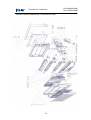
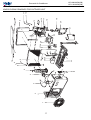
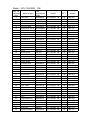
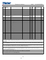
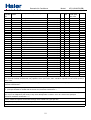
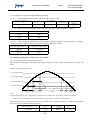
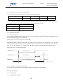
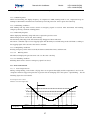
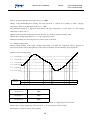
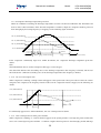
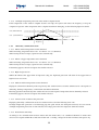
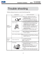
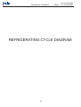
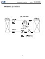
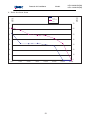
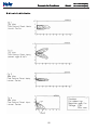
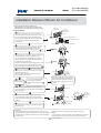
1
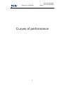
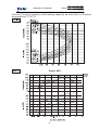
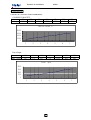
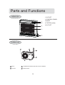
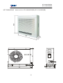
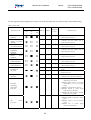
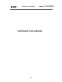
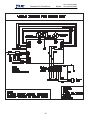
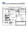
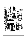
Domestic Air Conditioner
SERVICE MANUAL
Models
HFU-09H03/R2(DB)
HFU-12H03/R2(DB)
Features
International well-known compressor,economic and convenience.
Novelty appearance,beautiful and generous.
Anti-fungus filtration, multi-layer of fresh air.
Powerful operation,adjust temperature quickly.
CFC free refrigerant for environmental protection.
Serial Number: 0010540329
Version
n:04.00
Edition: 2004-12-24
Domestic Air Conditioner
Model: HFU-09H03/R2(DB)
HFU-12H03/R2(DB)
Content
1.
2.
3.
4.
Description of product model coding and series introduction--3
Specifications -------------------------------------------------------------5
Curves of performance---------------------------------------------------8
Description,net dimensions and functions of main components
and accessories------------------------------------------------------------12
5. Knock-down drawings and part lists---------------------------------15
6. Brief introduction to electrical control functions-------------------22
7. Wiring diagram ----------------------------------------------------------34
8. Circuit diagram------------------------------------------------------------ 36
9. Abnormity diagnose-------------------------------------------------------38
10. Trouble shooting------------------------------------------------------------40
11. Refrigerating cycle diagram------------------------------------------42
12. Noise level test chart and air veloc ity distribution-------------------------44
13. Installation manual -----------------------------------------------------47
1
Domestic Air Conditioner
Model:
HFU-09H03/R2(DB)
HFU-12H03/R2(DB)
Features
1.comfortable:wide-angle airflow
The vertical dual-flap and horizontal wide-angle louvers ensure the cool(warm air reaches every
corner of the room.
2.Quiet operation
Fan With Random-pitched Blades.
Random-pitched blades help reduce operating noise while maintaining a high airflow rate.
3.Engergy efficient
The design of inner-grooved copper tube greatly increases the refrigerant contact area and the
efficiency of cooling/heating functions.
4.Convenience
Auto restart and washable panel:
The grille can be removed easil y and washed when necessary.Any series have the function then
even if the power falls when the unit is operating unit will automatically return to the operating
settings in use before the power failure when power is restored.
5.Wide variety of functions
24-Hour Timer:
24-hour timer allows users to select the exact time they would like the air conditioner to turn on
and to turn off.Timers on previous models operation based on the number of hours of desired
operation.
6.Night-set models
When the air conditioner is operationg on the timer-off circuit.The preset room temperature
gradually rises(going down in heating)before the unit stops as shown delow.Users can sleep
comfortably without sudden change in temperature.
7.Program”dry”
This function automatically reduces the level of humidity while maintaining the preset indoor
temperature.
2
Domestic Air Conditioner
Model: HFU-09H03/R2(DB)
HFU-12H03/R2(DB)
Description of product model
coding and series introduction
3
Model: HFU-09H03/R2(DB)
HFU-12H03/R2(DB)
Domestic Air Conditioner
Introductory Remarks
A. Description of coding rules of unit model
Coding rules and descriptions are as follows:
2
1
3
4
5
6
7
8
9
10
11
Refrigerant type:R1(R407C),R2(R410A)
Applicable voltage:3(220~230V),4(240V)
Applicable frequency:0(50HZ),1(60HZ)
Developing sequence :A,B,C,D...
L/C-cooling only
Function code R/H-heat pump
E-electric aided heating
Nominal cooling capacity (BTU/h)with the first two
numbers based on thousand unit
The structure code of indoor & outdoor unit: S(wall-mounted),W(window type),P (cabinet type)
H-Abbreviation of Haier
Examples:
H2SM-18HS03/R2,It represents wall-mounted split type heat pump air conditioner .The cooling
capacity is 18000BTU/h,and the power supply is 220-230V/50Hz,”S” means the developing
sequence,"2"means one by two,and"R2" means the refrigerant is R410A.
B.Standard Situation/Conditions
WB C
outdoor air status
DBOC
WBOC
27 C
19 OC
35 OC
24 OC
Norminal heating
20 OC
not control
7 OC
6C
Norminal electrical
heating
---
---
---
No.
Operating condition
indoor air status
DBOC
1
Norminal cooling
2
3
O
O
---
4
O
Domestic Air Conditioner
Model: HFU-09H03/R2(DB)
HFU-12H03/R2(DB)
Specifications
5
Model: HFU-09H03/R2(DB)
HFU-12H03/R2(DB)
Domestic Air Conditioner
Model: HFU-09H03/R2(DB)
Cooling capacity(W)
2800
Heating capacity(W)
3150
Cooling coefficient(W/W)
3.46
Heating coefficient(W/W)
3.62
Cooling power input(W)
810
Heating power input(W)
870
1.0X10⁻³
Frequency range(Hz)
50
3
Moiture removal(m /h)
Operating voltage range (V)
O
Operating temp. range ( C )
O
220-230 ~
Refrigerant type
-7-43
Air sending angle
Variation of temp. adjust ( C )
+1
Climate type:
T1
Indoor unit noise
40/36/31
Net dimensions mm
(indoor unit)
Packaging dimensions mm
(indoor unit)
Net/gross weight (kg)
(indoor unit)
720*205*630
780*280*690
17/20
Max. mounting height
difference(m)
10
Refrigerant charge(g)
(R410A)
640
Fan type
R410A
O
60
indoor unit
Cross flow fan
outdoor unit
Axial flow fan
Class of electric shock
Outdoor unit noise
Net dimensions mm
(outdoor unit)
Packaging dimensions mm
(outdoor unit)
Net/gross weight (kg)
(outdoor unit)
Piling layers
Current entering side
(indoor/outdoor)
Indoor
TOSHIBA
DA89X1C-20FZ
Compressor oil type
Refrigerant recharged(Length
of connecting pipe is more
than 5 meter)
Cap. tube type muffle
model:
Fan speed(H/M/L)(r/min)
(indoor unit)
Fan speed(r/min)
two-way
Cut-off vavle(inch)
three-way
Max. operating pressure at
warm side(Mpa)
Compressor protector type
NMOCZE-Gles RB68EP or
Equivdent
B130-150-241E
length(mm)
2000
diametre(mm)
16
drain hose
20g per meter
TP2Y
1000/900/800
900
(outdoor unit)
30/35
4
Compressor model
15
930*340*620
outdoor unit
Compressor manufacturer
Maxi. length of connecting
pipe (m)
780*245*540
8
Once/2 weeks
270
48
indoor unit
Frequency of filter cleaning
Compressor oil charge (cc)
I
1/4
3/8
4.15
Type of tube of evaporator
and condenser
Size of tube of evaporator and
condenser(mm)
Appearance features of indoor
unit
Appearance features of outdoor
unit
Max. operating pressure at cool
side(Mpa)
6
Internal treaded
Dia. 7 / 7
console type
Metal type
4.15
Model: HFU-09H03/R2(DB)
HFU-12H03/R2(DB)
Domestic Air Conditioner
Model: HFU-12H03/R2(DB)
Cooling capacity(W)
3900
Heating capacity(W)
4100
Cooling coefficient(W/W)
3.51
Heating coefficient(W/W)
3.42
Cooling power input(W)
1110
Heating power input(W)
3
1.3X10⁻³
Moiture removal(m /h)
Operating voltage range (V)
O
Operating temp. range ( C )
O
220-230 ~
Refrigerant type
-7-43
Air sending angle
Variation of temp. adjust ( C )
+1
Climate type:
T1
Indoor unit noise
41/37/31
Net dimensions mm
(indoor unit)
Packaging dimensions mm
(indoor unit)
Net/gross weight (kg)
(indoor unit)
Frequency range(Hz)
720*205*630
780*280*690
17/20
Max. mounting height
difference(m)
15
Refrigerant charge(g)
(R410A)
640
Fan type
50
R410A
O
60
indoor unit
Cross flow fan
outdoor unit
Axial flow fan
Class of electric shock
Outdoor unit noise
Net dimensions mm
(outdoor unit)
Packaging dimensions mm
(outdoor unit)
Net/gross weight (kg)
(outdoor unit)
Piling layers
1200
I
53
780*245*540
930*340*620
30/35
indoor unit
8
outdoor unit
4
Current entering side
(indoor/outdoor)
Indoor
Frequency of filter cleaning
Once/2 weeks
Compressor manufacturer
SANYOO
Compressor model
C-6RZ092H1A
Compressor oil type
FV-68S
Compressor oil charge (cc)
350
Maxi. length of connecting
pipe (m)
15
Refrigerant recharged(Length
of connecting pipe is more
than 5 meter)
Cap. tube type muffle
model:
Fan speed(H/M/L)(r/min)
(indoor unit)
Fan speed(r/min)
two-way
Cut-off vavle(inch)
three-way
Max. operating pressure at
warm side(Mpa)
---------------
length(mm)
2000
diametre(mm)
16
drain hose
20g per meter
TP2Y
1000/900/800
900
(outdoor unit)
Compressor protector type
1/4
3/8
4.15
Type of tube of evaporator
and condenser
Size of tube of evaporator and
condenser(mm)
Appearance features of indoor
unit
Appearance features of outdoor
unit
Max. operating pressure at cool
side(Mpa)
7
Internal treaded
Dia. 7 / 7
console type
Metal type
4.15
Domestic Air Conditioner
Model:
HFU-09H03/R2(DB)
HFU-12H03/R2(DB)
Curves of performance
8
Domestic Air Conditioner
Model:
HFU-09H03/R2(DB)
HFU-12H03/R2(DB)
Curves of cooling capacity and heating capacity as a function of outdoor
temperature(-7OC~43OC)
9
Domestic Air Conditioner
Model:
C-6RZ092H1A
CURVES OF CAPACITY AND POWER INPUT.
COOLING CAPACITY
Hz
Cooling
30
1244
50
2321
60
2833
80
3983
90
4502
110
5565
120
6246
COOLING CAPACITY
8000
6000
4000
2000
0
1
2
3
4
30
387
50
570
60
691
5
6
7
Power Input
Hz
Power Input
80
973
90
1109
110
1465
120
1605
Power Input
2000
1500
1000
500
0
1
2
3
4
10
5
6
7
HFU-09H03/R2(DB)
Domestic Air Conditioner
Model: HFU-09H03/R2(DB)
Curves of compressor performance
Compressor: DA89X1C-20FZ
DA89XIC-20FZ
Model:HFU-09H03/R2(DB)
SUCTION GAS TEMP OC
35
UNDER COOL OC
8.3
Ambient temp OC
35
60.0
60.0
55.0
50.0
45.0
5.5
4.5
3.5
2.5
input (W)
1200
1000
60.0
800
55.0
50.0
45.0
capacity (W)
600
4000
45.0
50.0
55.0
60.0
3500
3000
2500
2000
1500
1000
500
-5
5
-0
evaporating temp C
O
11
10
Condensing temp OC
curent (A)
6.5
Domestic Air Conditioner
Model:
HFU-09H03/R2(DB)
HFU-12H03/R2(DB)
Description,dimension and function of
main components and accessories
12
Parts and Functions
Indoor unit
1.OUTLET
2.CONTROL PANEL
3.INLET
4.FILTER (inside)
5.OUTLET
Outdoor unit
INLET
CONNECTING PIPING AND ELECTRICAL WIRING
OUTLET
DRAIN HOSE
13
HFU-09H03/R2(DB)
HFU-12H03/R2(DB)
630
NET DIMENSIONS: Indoor unit for HFU-09H03/R2(DB) HFU-12H03/R2(DB)
720
5
68
540
20
140
500
780
62
845
15
123
55
256
286
14
67
Domestic Air Conditioner
Model:
HFU-09H03/R2(DB)
HFU-12H03/R2(DB)
Knock-down drawings
15
Domestic Air Conditioner
el
KNOCK-DOWN DRAWINGS FOR INDOOR UNIT
16
HFU-09H03/R2(DB)
HFU-12H03/R2(DB)
Domestic Air Conditioner
HFU-09H03/R2(DB)
HFU-12H03/R2(DB)
el
19
22
25 26
1
2
3
4
23
5
7
10
8
24
6
27 28 29
15
16
30
21
20
9
13
18
14
17
11
12
KNOCK-DOWN DRAWINGS FOR OUTDOOR UNIT
17
Model: HFU-09H03/R2
NO. In
exploded
view
1
2
3
4
5
6
7
8
9
10
11
12
13
14
15
16
17
18
19
20
21
22
23
24
25
26
27
28
29
30
31
32
33
34
35
36
37
38
39
40
41
42
43
DB
Name of part
Part
specialized
code
Model
Front grille
Air purifying filter
Button
Front panel
Heat exchanger
Temperature sensor
DOWN Motor cover
Bearing
Bearing
Flap
Air outlet assy
Bottom plate
Plate cushion
Back panel
Screw
Screw
Screw washer
Screw
Swing motor
Motor
Display board
UP Motor cover
Control box shell
Control box
Main board
Power board
Service cover
Teminal block
Wiring clamp
Screw
Screw
Hand switch
Slect board
Motor
Flap
Drain pan assy
Wires
DOWN Below fan
Up fan
Cover panel
Screw
Power wire
Remote controller
0010800954
0010201169
0010201288
0010800923
0010706830
001A3900059
0010800928
0010201176
0010201176
0010201191
0010800930
0010800924
0010800932
0010100571
5002008
5002116
5401031
5002118
0010400935
0010400933
-----0010800926
0010100572
0010201188
0010403628
-----0010201189
0010400931
0010201269
5002099
5002236
0010201275
-----0010400934
0010201209
0010201208
0010400932
0010201184
0010201175
0010201281
5002236
4200094
0010401605
HFU-09H03/R2
HFU-09H03/R2
HFU-09H03/R2
HFU-09H03/R2
HFU-09H03/R2
HFU-09H03/R2
HFU-09H03/R2
HFU-09H03/R2
HFU-09H03/R2
HFU-09H03/R2
HFU-09H03/R2
HFU-09H03/R2
HFU-09H03/R2
HFU-09H03/R2
HFU-09H03/R2
HFU-09H03/R2
HFU-09H03/R2
HFU-09H03/R2
HFU-09H03/R2
HFU-09H03/R2
HFU-09H03/R2
HFU-09H03/R2
HFU-09H03/R2
HFU-09H03/R2
HFU-09H03/R2
HFU-09H03/R2
HFU-09H03/R2
HFU-09H03/R2
HFU-09H03/R2
HFU-09H03/R2
HFU-09H03/R2
HFU-09H03/R2
HFU-09H03/R2
HFU-09H03/R2
HFU-09H03/R2
HFU-09H03/R2
HFU-09H03/R2
HFU-09H03/R2
HFU-09H03/R2
HFU-09H03/R2
HFU-09H03/R2
HFU-09H03/R2
HFU-09H03/R2
DB
DB
DB
DB
DB
DB
DB
DB
DB
DB
DB
DB
DB
DB
DB
DB
DB
DB
DB
DB
DB
DB
DB
DB
DB
DB
DB
DB
DB
DB
DB
DB
DB
DB
DB
DB
DB
DB
DB
DB
DB
DB
DB
QTY.
remark
1
1
1
1
1
1
1
2
2
1
1
1
1
1
1
1
1
1
1
1
1
1
1
1
1
1
1
1
1
1
1
1
1
1
1
1
1
1
1
1
1
1
1
indoor unit
indoor unit
indoor unit
indoor unit
indoor unit
indoor unit
indoor unit
indoor unit
indoor unit
indoor unit
indoor unit
indoor unit
indoor unit
indoor unit
indoor unit
indoor unit
indoor unit
indoor unit
indoor unit
indoor unit
indoor unit
indoor unit
indoor unit
indoor unit
indoor unit
indoor unit
indoor unit
indoor unit
indoor unit
indoor unit
indoor unit
indoor unit
indoor unit
indoor unit
indoor unit
indoor unit
indoor unit
indoor unit
indoor unit
indoor unit
indoor unit
indoor unit
indoor unit
Model: HFU-12H03/R2
NO. In
exploded
view
Name of part
DB
Part
specialized
code
Model
QTY.
remark
1
Front grille
0010800954
HFU-12H03/R2
DB
1.00
indoor unit
2
Air purifying filter
0010201169
HFU-12H03/R2
DB
1.00
indoor unit
3
Button
0010201288
HFU-12H03/R2
DB
1.00
indoor unit
4
Front panel
0010800923
HFU-12H03/R2
DB
1.00
indoor unit
5
Heat exchanger
0010706824
HFU-12H03/R2
DB
1.00
indoor unit
6
Temperature sensor 001A3900059 HFU-12H03/R2 DB
1.00
indoor unit
7
DOWN Motor cover
0010800928
HFU-12H03/R2
DB
1.00
indoor unit
8
Bearing
0010201176
HFU-12H03/R2
DB
2.00
indoor unit
9
Bearing
0010201176
HFU-12H03/R2
DB
2.00
indoor unit
10
Flap
0010201191
HFU-12H03/R2
DB
1.00
indoor unit
11
Air outlet assy
0010800930
HFU-12H03/R2
DB
1.00
indoor unit
12
Bottom plate
0010800924
HFU-12H03/R2
DB
1.00
indoor unit
13
Plate cushion
0010800932
HFU-12H03/R2
DB
1.00
indoor unit
14
Back panel
0010100571
HFU-12H03/R2
DB
1.00
indoor unit
15
Screw
5002008
HFU-12H03/R2
DB
1.00
indoor unit
16
Screw
5002116
HFU-12H03/R2
DB
1.00
indoor unit
17
Screw washer
5401031
HFU-12H03/R2
DB
1.00
indoor unit
18
Screw
5002118
HFU-12H03/R2
DB
1.00
indoor unit
19
Swing motor
0010400935
HFU-12H03/R2
DB
1.00
indoor unit
20
Motor
0010400933
HFU-12H03/R2
DB
1.00
indoor unit
21
Display board
------
HFU-12H03/R2
DB
1.00
indoor unit
22
UP Motor cover
0010800926
HFU-12H03/R2
DB
1.00
indoor unit
23
Control box shell
0010100572
HFU-12H03/R2
DB
1.00
indoor unit
24
Control box
0010201188
HFU-12H03/R2
DB
1.00
indoor unit
25
Main board
0010403628
HFU-12H03/R2
DB
1.00
indoor unit
26
Power board
------
HFU-12H03/R2
DB
1.00
indoor unit
27
Service cover
0010201189
HFU-12H03/R2
DB
1.00
indoor unit
28
Teminal block
0010400931
HFU-12H03/R2
DB
1.00
indoor unit
29
Wiring clamp
0010201269
HFU-12H03/R2
DB
1.00
indoor unit
30
Screw
5002099
HFU-12H03/R2
DB
1.00
indoor unit
31
Screw
5002236
HFU-12H03/R2
DB
1.00
indoor unit
32
Hand switch
0010201275
HFU-12H03/R2
DB
1.00
indoor unit
33
Slect board
------
HFU-12H03/R2
DB
1.00
indoor unit
34
Motor
0010400934
HFU-12H03/R2
DB
1.00
indoor unit
35
Flap
0010201209
HFU-12H03/R2
DB
1.00
indoor unit
36
Drain pan assy
0010201208
HFU-12H03/R2
DB
1.00
indoor unit
37
Wires
0010400932
HFU-12H03/R2
DB
1.00
indoor unit
38
DOWN Below fan
0010201184
HFU-12H03/R2
DB
1.00
indoor unit
39
Up fan
0010201175
HFU-12H03/R2
DB
1.00
indoor unit
40
Cover panel
0010201281
HFU-12H03/R2
DB
1.00
indoor unit
41
Screw
5002236
HFU-12H03/R2
DB
1.00
indoor unit
42
Power wire
4200094
HFU-12H03/R2
DB
1.00
indoor unit
43
Remote controller
0010401605
HFU-12H03/R2
DB
1.00
indoor unit
Domestic Air Conditioner
Model:
HFU-09H03/R2(DB)
Edition:2005/03/14
No. in
explode
d view
1
2
3
4
5
6
Spare parts
number
Spare parts description in english
Model
001A0100017
001A1101009
0010203662
0010403487
0010100419
0010706498
Front grille
Front panel
Fan
Motor
Frame for motor
Heat exchanger
HFU-09H03/R2(DB)
HFU-09H03/R2(DB)
HFU-09H03/R2(DB)
HFU-09H03/R2(DB)
HFU-09H03/R2(DB)
HFU-09H03/R2(DB)
1
1
1
1
1
1
7
001A5736055
Fixed clip
sensor
HFU-09H03/R2(DB)
1
8
9
10
11
12
13
14
15
16
17
18
19
20
21
22
23
24
25
26
27
28
29
30
001A3800082
0010101388
001A1101010
001A3900056
001A3900055
0010706509
0010706497
0010403022
0010704488
0010705988
0010705255
001A5102050
0010706492
001A17621544
001A1101014
001A1436042
0010804196
001A0100427
0010403365
0010403368
0010403521
0010403520
001A4000105
Temperature sensor
Back panel
Top panel
Compressor temperature sensor
Tube temperature sensor
Entering gas pipe
Capillary Tube
4-way valve coil
4-way valve
Stop valve
Stop valve
Flange Nut
Compressor
Cushion
Bottom plate
Service cover
Separating plate
Reactor box
Reactor
Power Module
PCB
Capacitor board
Terminal Block
HFU-09H03/R2(DB)
HFU-09H03/R2(DB)
HFU-09H03/R2(DB)
HFU-09H03/R2(DB)
HFU-09H03/R2(DB)
HFU-09H03/R2(DB)
HFU-09H03/R2(DB)
HFU-09H03/R2(DB)
HFU-09H03/R2(DB)
HFU-09H03/R2(DB)
HFU-09H03/R2(DB)
HFU-09H03/R2(DB)
HFU-09H03/R2(DB)
HFU-09H03/R2(DB)
HFU-09H03/R2(DB)
HFU-09H03/R2(DB)
HFU-09H03/R2(DB)
HFU-09H03/R2(DB)
HFU-09H03/R2(DB)
HFU-09H03/R2(DB)
HFU-09H03/R2(DB)
HFU-09H03/R2(DB)
HFU-09H03/R2(DB)
1
1
1
1
1
1
1
1
1
1
1
3
1
1
1
1
1
1
1
1
1
1
1
forenviroment
temp.
QTY Failure
.
rate
The proportion remark
of the spare part
stock
*
*
*
*
*
*
*
*
*
*
*
1,The failer rate and the proportion of the spare-part stock are regarded as the reference of the stock for spare-parts;The first
time should be stocked accroded with the proportion of the spare-parts,and it should be adjusted with the actual quantity 3
months later.
2,easy-damaged;The spare-part which is often damaged and the customer must stock in the spare-parts warehouse,and
should be marked with"*"
3,possible damaged:The spare-part which is not often damaged like the easy damaged one and the customer may stock in
the spare-part warehouse accord with the actual case,should be marked with " ".
4,not need provided :The spare-part which is seldom damaged or the maintenance man could not maitmains.The spare
parts may be air freighted by the factory if they were damaged.The customer nees not stock in the spare-part
warehouse,should be marked with " x ".
5,Above should be improved accord with the reply of the market half a year per time.
6.The spare parts price on net is FOB Qingdao term.
20
26
Domestic Air Conditioner
Model:
HFU-12H03/R2(DB)
Edition:2004/09/20
No. in
exploded
view
1
2
3
4
5
6
7
8
9
10
11
12
13
14
15
16
17
18
19
20
21
22
23
24
25
26
27
28
29
30
Spare parts
number
Spare parts description in english
Model
001A0100017
001A1101009
0010203662
0010403508
0010100419
0010706505
001A5736055
001A3800082
0010101388
001A1101010
001A3900056
001A3900055
0010706502
0010706504
001A2500076
0010703501
0010705256
0010705255
001A5102050
0010706499
001A17621544
001A1101014
001A1436042
0010804196
001A0100427
0010403365
0010403368
0010403519
0010403520
001A4000105
Front grille
Front panel
Fan
Motor
Frame for motor
Heat exchanger
Fixed clip forenviroment temp. sensor
Temperature sensor
Back panel
Top panel
Compressor temperature sensor
Tube temperature sensor
Entering gas pipe
Capillary Tube
4-way valve coil
4-way valve
Stop valve
Stop valve
Flange Nut
Compressor
Cushion
Bottom plate
Service cover
Separating plate
Reactor box
Reactor
Power Module
PCB
Capacitor board
Terminal Block
HFU-12H03/R2(DB)
HFU-12H03/R2(DB)
HFU-12H03/R2(DB)
HFU-12H03/R2(DB)
HFU-12H03/R2(DB)
HFU-12H03/R2(DB)
HFU-12H03/R2(DB)
HFU-12H03/R2(DB)
HFU-12H03/R2(DB)
HFU-12H03/R2(DB)
HFU-12H03/R2(DB)
HFU-12H03/R2(DB)
HFU-12H03/R2(DB)
HFU-12H03/R2(DB)
HFU-12H03/R2(DB)
HFU-12H03/R2(DB)
HFU-12H03/R2(DB)
HFU-12H03/R2(DB)
HFU-12H03/R2(DB)
HFU-12H03/R2(DB)
HFU-12H03/R2(DB)
HFU-12H03/R2(DB)
HFU-12H03/R2(DB)
HFU-12H03/R2(DB)
HFU-12H03/R2(DB)
HFU-12H03/R2(DB)
HFU-12H03/R2(DB)
HFU-12H03/R2(DB)
HFU-12H03/R2(DB)
HFU-12H03/R2(DB)
QTY Failure The proportion remark
.
rate
of the spare
part stock
1
1
1
*
1
*
1
1
1
1
*
1
1
1
*
1
*
1
1
1
*
1
1
1
3
1
*
1
1
1
1
1
1
*
1
*
1
*
1
*
1
1,The failer rate and the proportion of the spare-part stock are regarded as the reference of the stock for spare-parts;The first
time should be stocked accroded with the proportion of the spare-parts,and it should be adjusted with the actual quantity 3
months later.
2,easy-damaged;The spare-part which is often damaged and the customer must stock in the spare-parts warehouse,and
should be marked with"*"
3,possible damaged:The spare-part which is not often damaged like the easy damaged one and the customer may stock in
the spare-part warehouse accord with the actual case,should be marked with " ".
4,not need provided :The spare-part which is seldom damaged or the maintenance man could not maitmains.The spare
parts may be air freighted by the factory if they were damaged.The customer nees not stock in the spare-part
warehouse,should be marked with " x ".
5,Above should be improved accord with the reply of the market half a year per time.
6.The spare parts price on net is FOB Qingdao term.
21
Domestic Air Conditioner
Model:
HFU-09H03/R2(DB)
HFU-12H03/R2(DB)
Brief introduction to electrical
control function
22
Domestic Air Conditioner
HFU-09H03/R2(DB)
HFU-12H03/R2(DB)
Model:
1. Introduction to electrical control function
Including brief introduction to air conditioners of series models and electrical control function as well as the technical
information.
1.1 Brief introduction to electrical function
1.1.1 Status conversion
As the following figure:
Press Emergency 10-15
Unit stops
Remote
Control Stops
Malfunction meter
Press Emergency or
Remote Control to stop
Timer
Operation
Timer
Trial running
Abnormity Diagnose
Cool
Emergency Cool
Sensor Abnormity
Dehumidify
Emergency Heat
Heat
1.1.2
Automatic function (automatic running function is selected after pressing emergency button 0-5s)
1.1.2.1 Status conversion under automatic running
As the following figure:
Ambient Temp.
Cool (setting temp. 26嘙C)
23嘙C
Heat (setting temp. 23嘙C)
When running in the automatic emergency status, indoor unit can receive the remote controller’ s signal to convert
status.
1.1.2.2 Air volume control under automatic running
Wind speed of indoor fan is automatically adjusted when automatic running, refer to air volume control under
cool/heating running for details.
1.1.2.3 Frequency control for compressor under automatic running
It is the same as the frequency control for compressor under cool/heating running.
23
Domestic Air Conditioner
HFU-09H03/R2(DB)
HFU-12H03/R2(DB)
Model:
1.1.2 Cooling running
1.1.2.1 Air volume control under cooling running (Cool compensation temp. – 0.33嘙C)
When setting manual control, wind speed will run accord to the setting value during compressor running, and run
in the speed of setting value minus 60rpm during compressor stopping.
When setting automatic wind speed, its velocity is related to temperature difference
compensation temp. setting temp. ). See the following table for details:
Temperature difference
(嘙C)
T> 4.3
Wind speed
4.3
High
T
0.3
T (
ambient temp.
T < 0.3
Middle
Low
1.1.2.2 Compressor control under cooling running
1.1.2.2.1 when running in normal status, control of compressor frequency:
Temperature difference
C)
(嘙
4.3
T> 4.3
Maximum frequency (Hz)
T
High frequency
T
1.3
1.3
Mid. frequency
-1
T < -1
Compressor
stop
Low frequency
1.1.2.2.2 when running in cool mode, the setting air volume restricts frequency as follows:
Setting air volume
Maximum frequency (Hz)
Middle
90 Hz
Low
52 Hz
1.1.2.2.3 when running in cool mode, the outdoor ambient temperature restricts frequency as follows: (only
applying to the machine models with outdoor ambient temperature sensor).
Outdoor ambient temp. (嘙C)
T
Maximum frequency (Hz)
No limitation
26
60 Hz
T < 26
1.1.3 Dehumidification running
1.1.3.1 Air volume control under dehumidification running (Cool compensation temperature – 0.33嘙C)
Except for the first running that fan runs in low speed during compressor stopping, fan stops during compressor
OFF.
When setting manual control, wind speed runs according to the following table during compressor running:
Temperature difference
C)
(嘙
Wind speed
T
0.3
T < 0.3
Setting
Low
When setting automatic wind speed, its velocity is related to temperature difference (ambient temp. setting
temp.). See the following table for details:
Temperature difference
Wind speed
(嘙C)
T> 4.3
High
24
4.3
T
Middle
0.3
T < 0.3
Low
Domestic Air Conditioner
HFU-09H03/R2(DB)
HFU-12H03/R2(DB)
Model:
1.1.3.2 Compressor control under dehumidification running
1.1.3.2.1
When running in normal status, control of compressor frequency:
Temperature difference
C)
(嘙
Maximum frequency (Hz)
1.1.3.2.2
T
4.3
T> 4.3
High frequency
T
1.3
1.3
Mid. frequency
-1
T < -1
Compressor
stop
Low frequency
When running in dehumidify mode, the setting air volume restricts frequency as follows:
Setting airflow
Maximum frequency (Hz)
Middle
90 Hz
Low
52 Hz
1.1.3.2.3 When running in dehumidify mode, the outdoor ambient temperature restricts frequency as follows:
(only applying to the machine models with outdoor ambient temperature sensor).
Maximum frequency (Hz)
Outdoor ambient temp. (嘙C)
T
No limitation
26
60 Hz
T < 26
1.1.4 Heating running (heat compensation temp. 4.67嘙C)
1.1.4.1 Air volume control under heating running
When heating running starts, defrosting stops. When compressor restarts, it shall be warm start to prevent cold
wind.
Thermal conversion temperature:
35.1嘙C (undetermined)
35.1嘙C (undetermined)
25.2嘙C (undetermined)
15 嘙C (undetermined)
* Select higher wind speed after 4 minutes
stop
Lower
Low
setting
Low
Lower stop
Note:
For different machine type, the “ undetermined” parameters is also different, here only take this example for illustration.
“ * ” Indicating that if unit maintains in this wind speed for more than 4 minutes, it then select higher speed.
When setting automatic wind speed, its velocity is related to the temperature difference (including compensation
temperature), see the following table for details:
Temperature difference
Wind speed
(嘙C)
T> 4.3
High
25
4.3
T
Middle
0.3
T < 0.3
Low
Domestic Air Conditioner
HFU-09H03/R2(DB)
HFU-12H03/R2(DB)
Model:
1.1.4.2 Compressor control under heating running
1.1.4.2.1 When running in normal status, control of compressor frequency:
Temperature difference
C)
(嘙
Maximum frequency (Hz)
T
4.3
T> 4.3
1.3
1.3
High frequency
Mid. frequency
T
-1
Low frequency
T < -1
Compressor
stops
1.1.4.1.2 When running in dehumidify mode, the outdoor ambient temperature restricts frequency as follows:
(only applying to the machine models with outdoor ambient temperature sensor).
Maximum frequency (Hz)
Outdoor ambient temp. (嘙C)
T
60 Hz
15
No limitation
T < 15
1.1.5 Defrosting running
1.1.5.1 Defrosting process
When defrosting during heating operation, frequency is not controlled according to the temperature difference, and
the maximum heating frequency is displayed.
Compressor does not stop in the process of defrosting.
Defrosting beginning conditions: Heat mode, the first power on operation or the lasting time to the previous
defrosting finishing is more than 47 minutes, and the outdoor ambient temperature is continuously found to be less
than -4嘙C ( model: 26, 28) or -5嘙C (model: 32, 36, 40) during compressor running, and then defrosting starts.
Defrosting process as following illustration:
Outdoor fan
Defrosting process
4-way valve
Defrosting process
Compressor
55S
5S
55S
Defrosting process
60S
Defrosting finish
compressor restart
1.1.5.2 Air volume control during defrosting
20 seconds Low wind is firstly selected during defrosting, then indoor fan stops running.
1.1.6 Special function
1.1.6.1 Trial running
1.1.6.1.1 Beginning conditions
26
Domestic Air Conditioner
HFU-09H03/R2(DB)
HFU-12H03/R2(DB)
Model:
Pressing emergency button 5-10 seconds and buzzer sounding twice, then starts.
1.1.6.1.2 Running status
When in trial running, the display frequency of compressor is 58Hz, running mode is cool, compressor keeps on
running for 30 minutes and will not be restricted by low-load protection (refer to protection function).
1.1.6.1.3 Finishing conditions
Trial running will stop when remote control or emergency signal is received. After 30 minutes trial running,
emergency running (automatic running) starts.
1.1.6.2 Abnormity diagnose
When displaying abnormity, using indicator to express the previous error.
When having no error code record, show nothing.
The abnormity indicating mode will automatically disappeared 30 seconds later.
The remote controller only receives stopping signal and abnormity record indicating mode will finish according to
the stopping signal of the switch or the remote controller.
1.1.6.2.1 Beginning conditions
Pressing emergency switch 10-15 seconds, the buzzer sounds three times, and then start.
1.1.6.2.2 Running status
The indicator displays the previous error code (see the error code list).
1.1.6.2.3 Finishing condition
Finishing when remote control or emergency signal is received.
1.1.7 Protection function
1.1.7.1 Low-load protection
During cooling running, if the indoor coil-pipe does not evaporate thoroughly and the temperature is too low, the
compressor must be stopped for protection to prevent it from damaging due to the system “ liquid hitting” . See the
following figure for action details:
Low-load protection control:
Thermal conversion temperature:
2º C
-0.5º C
frequency
Normal
Normal
Min. frequency
27
Stop
Min
Limit
Domestic Air Conditioner
Model:
HFU-09H03/R2(DB)
HFU-12H03/R2(DB)
Indoor coil pipe temperature sensor type: R (25º C)=10Kȍ
During cooling-dehumidification running, low-load protection is carried out according to indoor coil-pipe
temperature; whereas, the displayed frequency is “ 58Hz” .
The minimum frequency is displayed when indoor coil- pipe temperature is lower than 2º C and coil-pipe
temperature is above -0.5º C.
When thermal conversion temperature is lower than 0.5º C, selecting 3 minutes stand-by status.
When indoor coil-pipe temperature is 2.1º C, the compressor restarts.
During trial running, the low-load protection control can be overlooked.
1.1.7.2 High-load protection
During heating running, if the indoor coil-pipe temperature is too high, the compressor must be stopped for
protection to prevent it from damaging due to the system overheating. See the following figure for details:
Thermal conversion temperature
67º C (undetermined)
62º C (undetermined)
51º C (undetermined)
49.2º C (undetermined)
47º C (undetermined)
45.2º C (undetermined)
Indicate
frequency
HFU-12H03(B)/R1
Stop
C
3 minutes standby
Frequency A
Parameters
80Hz
Frequency B
Frequency C
72Hz
50Hz
Frequency D
30Hz
C
B
A
B
C
Stop
When high-load protection is limited to act twice within 30 minutes, it is high-load protection alarm.
When indoor coil pipe temperature is lower than 45º C, it comes back to normal control.
The frequency of high load protection is priority.
28
Domestic Air Conditioner
Model:
HFU-09H03/R2(DB)
HFU-12H03/R2(DB)
1.1.7.3 Compressor discharge temperature protection
When air conditioner is running, the discharge temperature need not to be detected within the first 10 minutes and
starts to detect after 10 minutes. If the detected temperature is found too high, the compressor shall be protected
from damaging by decreasing frequency or stopping, see the following figure for details:
120º C (undetermined)
113º C (undetermined)
108º C (undetermined)
80º C (undetermined)
release
normal
limit
stop (3 minutes stand-by)
stop
restore(compressor restarts)
If the compressor continuously stops twice within 30 minutes, the compressor discharge temperature protection
alarms.
Note:
The undetermined data are for the example machine type, not for all types.
The dotted line indicates the descending curve of the discharge temperature after frequency is limited, and the real
line indicates the continuous ascending curve of the discharge temperature after frequency is limited.
1.1.7.4 AC over-current protection
When compressor is running, overhigh current will appear if the system load is heavy. In order to reduce the current
and protect the compressor, the frequency must be reduced or the compressor must be stopped, see the following for
details:
7.2A (undetermined)
5.8A (undetermined)
5.1A (undetermined)
normal
limit
reduce
frequency
unit stops (3 minutes stand-by)
restore
If continuously appears twice within 30 minutes, AC over-current protection alarms.
1.1.7.5 Over-current protection of the power module
When compressor is running, if “ rotation obstacle”appears or the system pressure is too high, the power module will
send “over-current signal of power module” to outdoor computer board to protect it from damaging and the unit stops
29
Domestic Air Conditioner
Model:
HFU-09H03/R2(DB)
HFU-12H03/R2(DB)
and alarms.
1.1.7.6 Overhigh temperature protection of the outdoor computer board
If the temperature of the outdoor computer board is too high, the system will reduce the frequency or stop the
compressor to protect other components on the computer board from damaging, see the following figure for details:
75ºC (undetermined)
75ºC (undetermined)
normal
1.1.8
reduce
frequency
unit stop ( 3 minutes stand-by)
restore
Abnormity confirmation alarm
1.1.8.1 Indoor ambient temperature sensor abnormal
When in running, temperature above 126º C or below -31º C is abnormal.
When leaving the above ranges, operation resets automatically.
1.1.8.2 Indoor coil pipe temperature sensor abnormal
When in running, temperature above 196º C or below -53º C is abnormal.
When leaving the above ranges, operation resets automatically.
If abnormity appears, the low-load protection shall be released.
1.1.8.3 High-load protection
Within 30 minutes after upper limit of high-load acting, the high-load protection will alarm if the upper limit of
high-load acts once more.
1.1.8.4 Outdoor ambient temperature sensor abnormal
Displayed as thermistor abnormity mode respectively after outdoor unit received the abnormal error code signals of
defrosting, discharge temperature, control board and outdoor thermistor.
Resetting operation automatically after outdoor unit received the signal of temperature sensor abnormity released.
If abnormity appears, the low-load protection shall be released.
1.1.8.5 Control action of outdoor unit protection
Displaying abnormity confirmation mode since outdoor unit received the following error code:
Overhigh temperature protection of air discharge pipe, DC peak current, CT wiring disconnected, AC over-current,
overhigh temperature protection of control board, low-voltage protection and compressor abnormal rotation.
1.1.8.6 Transmission abnormity
According to the communication between indoor unit and outdoor unit, it is considered abnormal if outdoor unit
cannot receive signals within 20 seconds after indoor unit’ s sending. (Except for the first 2 minutes after power on).
30
Domestic Air Conditioner
Model:
HFU-09H03/R2(DB)
HFU-12H03/R2(DB)
It is regarded as transmission abnormity after outdoor unit receives the signal of transmission abnormity.
Transmission abnormity is released by running stopping.
1.1.8.7 EEPROM
When power on, EEPROM is abnormal if the control parameters and the checking total amount are not identical.
EEPROM is considered abnormal since the outdoor received the abnormal signal of EEPROM.
At the same time, remote control and emergency running are not accepted.
It is only can be released by power blackout.
List of error code
Error display
Abnormity mode
Powe
r
Time
r
Run
ning
Abnormity of indoor
thermistor
Abnormity of thermal
conversion thermistor
Abnormity of defrosting
thermistor
Abnormity
of
discharging thermistor
Abnormity of control
board thermistor
Abnormity of module
thermistor
Abnormity of outdoor
thermistor
Indoor
Outdoor
Automatic
restore
*
*
*
*
*
*
*
*
*
*
*
*
*
*
*
Transmission abnormity
*
Compressor
running
abnormity
Overhigh
discharging
temperature protection
*
*
AC current protection
*
DC current protection
*
Insufficient
current
protection
Outdoor control board
temperature protection
Module
temperature
rising protection
*
*
*
High-load protection
*
CT wiring disconnected
protection
*
*
EEPROM abnormity
*
Note:
: Lightening
: Flashing
: Blackout
* Indicating that this function
is provided.
31
Domestic Air Conditioner
Model:
HFU-09H03/R2(DB)
HFU-12H03/R2(DB)
Parameter list of the main components
No.
Name
Type
Unit
Indoor
unit
Outdoor
unit
1
1
Optical coupler
TLP371
Piece
1
2
Optical
silicon
controlled rectifier
TLP3526
Piece
1
3
Rectifying bridge
S15VB60 (15A 600V)
Piece
4
Rectifying bridge
SINB60
Piece
5
Power module
TM-03
Piece
6
Relay
G4A-1A DC12V (20)A
Piece
7
Ceramic resonator
CST10.0MTW-TF01
Piece
8
Receiver
HS0038A2M
Piece
32
2
1
1
1
1
1
1
Remarks
Domestic Air Conditioner
Model:
HFU-09H03/R2(DB)
HFU-12H03/R2(DB)
For the appeared abnormal phenomena, please refer to the following table for trouble analysis and troubleshooting:
List of error code:
Error display
Po
we
r
Abnormity mode
Ti
m
er
Run
ning
Indoor
Outdoor
Automatic
restore
Possible reason
Abnormity of indoor
thermistor
*
*
1. Inserter does not contact well or
control board is not good.
Abnormity
of
thermal conversion
thermistor
*
*
1. Inserter does not contact well or
control board is not good.
*
*
1. Inserter does not contact well or
control board is not good.
*
*
1. Inserter does not contact well or
control board is not good.
*
*
1. Inserter does not contact well or
control board is not good.
Abnormity
of
module thermistor
*
*
1. Inserter does not contact well or
control board is not good.
Abnormity
of
outdoor thermistor
*
*
1. Inserter does not contact well or
control board is not good.
Abnormity
of
defrosting thermistor
Abnormity
discharging
thermistor
Abnormity
control
thermistor
of
of
board
*
Transmission
abnormity
*
Compressor running
abnormity
Overhigh
discharging
temperature
protection
AC
protection
current
33
1. There is great interference source
around
2. Incorrect wire connection or control
board is not good.
*
1. Check if compressor shaft is seized.
2. Whether power module is damaged
*
1. Whether system gas is insufficient or
charged gas is too much.
2. Whether system voltage is too high
(above242V) or too low (below
187V)
3. Whether capillary tube is blocked.
4. Whether sensors or control board
components are abnormal.
5. Whether the indoor/outdoor ambient
temperature is too high.
*
1. Whether system is charged too many
gases.
2. Whether voltage is too low (below
187V).
3. Whether CT or control board
component is abnormal.
Domestic Air Conditioner
Model:
HFU-09H03/R2(DB)
HFU-12H03/R2(DB)
It is regarded as transmission abnormity after outdoor unit receives the signal of transmission abnormity.
Transmission abnormity is released by running stopping.
1.1.8.7 EEPROM
When power on, EEPROM is abnormal if the control parameters and the checking total amount are not identical.
EEPROM is considered abnormal since the outdoor received the abnormal signal of EEPROM.
At the same time, remote control and emergency running are not accepted.
It is only can be released by power blackout.
List of error code
Error display
Abnormity mode
Powe
r
Time
r
Run
ning
Abnormity of indoor
thermistor
Abnormity of thermal
conversion thermistor
Abnormity of defrosting
thermistor
Abnormity
of
discharging thermistor
Abnormity of control
board thermistor
Abnormity of module
thermistor
Abnormity of outdoor
thermistor
Indoor
Outdoor
Automatic
restore
*
*
*
*
*
*
*
*
*
*
*
*
*
*
*
Transmission abnormity
*
Compressor
running
abnormity
Overhigh
discharging
temperature protection
*
*
AC current protection
*
DC current protection
*
Insufficient
current
protection
Outdoor control board
temperature protection
Module
temperature
rising protection
*
*
*
High-load protection
*
CT wiring disconnected
protection
*
*
EEPROM abnormity
*
Fan motor abnormity
Note:
*
: Lightening
: Flashing
: Blackout
* Indicating that this function
is provided.
34
Domestic Air Conditioner
Model:
HFU-09H03/R2(DB)
HFU-12H03/R2(DB)
OUTDOOR UNIT PART
Chapter I: Indoor Unit and Main board for Outdoor Unit
Notice:
During operations under any mode, if short circuit, open circuit and other
malfunctions of the temperature sensors are detected, the main engine should
come to a halt immediately.
1. Outdoor-board:
1.1.Forced cooling operation switch:
Short circuit this switch before electrifying, data communication to indoor unit
will be ignored:
Forced cooling will function, the 3-minute delay will be cancelled, and the
following output will be ON simultaneously:
High wind volume (H) for outdoor fan motor;
Compressor operates at the frequency of 80Hz.
1.2.Forced heating operation switch:
Short circuit this switch before electrifying, data communication to indoor unit
will be ignored:
Forced heating will function, the 3-minute delay will be cancelled, and the
following output will be ON simultaneously:
High wind volume (H) for outdoor fan motor;
Compressor operates at the frequency of 80Hz.
CPU checks all A/D ports
B When safeguarding action happens outdoors, the actions in A should be
OFF, and other inputs are independent of the actions in A.
C LED output: Goes along even if safeguarding action happens outdoors;
Cut this switch and go back to the original state. (The out-door safeguarding
action will continue)
Chapter II: Basic Functions
3. Cooling mode
3.1.The four-way valve does not work (not electrified)
3.2.The discharge temperature sensor will not be tested within five minutes
after the compressor is started
3.3.Outdoor fan motor control: The fan motor starts five seconds after the
compressor starts, switching conditions for the two gears of wind volume are
as follows:
T ambient temp. <21 , Low wind volume
T ambient temp. >21
, High wind
volume
When the fan motor starts up, and
the ambient temperature is at the return difference ( 2 ), it runs at the low
wind volume.
3.4.Compressor control: Frequency range: 30HZ---------120HZ
T ambient temp. <16 , the maximum frequency is
65HZ
16
T ambient temp. 30
the maximum
frequency is 90HZ
30
T ambient temp. 41
the maximum frequency is
110HZ
T ambient temp. 41
the maximum frequency is 85HZ
Actual temperature and frequency maybe adjusted through EEPROM
35
34
Domestic Air
Domestic
Air Conditioner
HFU-12H03/R2(DB)
Model: HFU-09H03/R2(DB)
4.Heating mode
4.1.The four-way valve is electrified 2 seconds after the compressor is
electrified
4.2.Malfunctions of the discharge temperature sensor will not be tested within
five minutes after the compressor is started
4.3.Outdoor fan motor control: The fan motor starts five seconds after the
compressor starts, switching conditions for the two gears of wind volume are
as follows:
T ambient temp. <16
, High wind
volume
T ambient temp.
16 , Low
wind volume
When the fan motor
starts up, and the ambient temperature is at the return difference ( 2 ), it
runs at the low wind volume.
4.4.Compressor control: Frequency range: 30HZ---------120HZ
T ambient temp. >22 , the maximum frequency is 70HZ
9
T ambient temp. 22
the maximum frequency is 90HZ
2
T ambient temp. 9
the maximum frequency is
100HZ
T ambient temp. <2
the maximum frequency is 110HZ
Actual temperature and frequency can be adjusted through EEPROM
4.5.Conditions to enter into the defrosting stage:
A
Conditions to enter into the defrosting stage
After the heating operation has begun, and the operation time of the compressor
adds up to 45 minutes (The total operation time of the compressor will be reset
to zero after defrosting or the operating mode switched into cooling), through
examining the defrosting sensor TE (Examining the frosting status of the outdoor
heat exchanger) and the ambient temperature sensor TA, if the following
conditions are met continuously up to 5 minutes, then defrosting operation is
entered:
TE C TA
Of which C TA 0
C=0.8
TA 0
C=0.3
maybe adjusted through EEPROM
For places easy to frost, set
as H; For places not easy to frost, set
as L; It
is set as M when leaving factory.
Temperature limit to enter into the defrosting stage -15 E C TA
2 E
B
Time interval of defrosting
While the calculated data of C TA
fall within the range of -15 E C
TA
, the time interval between two defrosting operation is 45 minutes
While the calculated data of C TA
fall within the range of C TA
-15 E, the time interval between two defrosting operation is 55 minutes
C Defrosting operation
When defrosting begins, the compressor and the outdoor fan motor stops,
and the four-way valve turns OFF 50 seconds later.
The compressor starts and stays at the frequency of 60HZ for 30 seconds,
then operates towards the target frequency (Can be adjusted through
EEPROM)
The current safeguard and the compressor discharge safeguard and
other means of safeguard remain valid while defrosting. If the compressor
36
35
Domestic Air Conditioner
HFU-12H03/R2(DB)
Model: HFU-09H03/R2(DB)
halts during the defrosting stage, remain still for 30 seconds, then
conducts defrosting operation if it is still within the defrosting stage, the
compressor starts according to the demand of the startup of the
defrosting compressor.
Entering into the defrosting stage, it must be guaranteed that the
minimum operation time of the compressor should amount at least to 2
minutes before exit defrosting.
D. Conditions to exit the defrosting stage
The defrosting operation will return to heating operation if any of the following
conditions is met.
1 The temperature of the outdoor heat exchanger remains above
7
(Can be adjusted through EEPROM) for over 80 seconds
continuously.
2
Keep defrosting operation for 9 minutes (Can be adjusted
through EEPROM) continuously.
E
After the condition to exit defrosting operation is met, work as
follows.
The compressor stops, the outdoor fan motor stops 50
seconds later, the four-way valve turns on, the compressor starts
according to the starting process.
Time sequence of the defrosting operation is as follows:
Compressor
Outdoors fan motor
Four-way valve
60
9Max
5.Outdoor condensation temperature control while cooling:
5.1.When the operation frequency F 40HZ, if the temperature of the
outdoor coiled pipe T outdoor coil 52 , decrease the operation frequency
of the compressor by 2Hz then examine the temperature of the outdoor
coiled pipe at 10-second intervals, if T outdoor coil 52 , decrease the
operation frequency further by 2Hz until the frequency is the lowest;
During the frequency-decreasing operation, if 47
T outdoor coil 52 , the
compressor and the fan motor keep their original states;
the compressor runs at the normal operating frequency, and the outdoor fan
motor returns to its original state,
5.2.When the operation frequency F 40HZ, if the temperature of the outdoor
coiled pipe T outdoor coil 57 , decrease the operation frequency of the compressor
by 2Hz then examine the temperature of the outdoor coiled pipe at 10-second
intervals, if T outdoor coil 57 , decrease the operation frequency further by 2Hz
until the frequency is the lowest;
During the frequency-decreasing operation, if 52
T outdoor coil 57 , the
compressor and the fan motor keep their original states;
When T outdoor coil 51 , the compressor runs at the normal operating frequency,
637
Domestic Air Conditioner
HFU-12H03/R2(DB)
Model: HFU-09H03/R2(DB)
and the outdoor fan motor returns to its original state;
The above temperature points, frequency-decreasing step and time interval can
all be adjusted through EEPROM
III. Anti over-loading operation while heating:
5.3.When the operation frequency F 40HZ, if the temperature of the outdoor
coiled pipe T outdoor coil 52 , the outdoor fan motor performs forced high-speed
operation and the operation frequency of the compressor should be decreased by
2Hz then examine the temperature of the outdoor coiled pipe at 10-second
intervals, if T outdoor coil 52 , decrease the operation frequency further by 2Hz
until the frequency is the lowest;
During the frequency-decreasing operation, if 47
T outdoor coil 52 , the
compressor and the fan motor keep their original states;
When T outdoor coil 46 , the compressor runs at the normal operating frequency,
and the outdoor fan motor returns to its original state;
5.4.When the operation frequency F 40HZ, if the temperature of the outdoor
coiled pipe T outdoor coil 57 , the outdoor fan motor performs forced high-speed
operation and the operation frequency of the compressor should be decreased by
2Hz then examine the temperature of the outdoor coiled pipe at 10-second
intervals, if T outdoor coil 57 , decrease the operation frequency further by 2Hz
until the frequency is the lowest;
During the frequency-decreasing operation, if 52
T outdoor coil 52 , the
compressor and the fan motor keep their original states
When T outdoor coil 51 , the compressor runs at the normal operating frequency,
and the outdoor fan motor returns to its original state;
The above temperature points, frequency-decreasing step and time interval can
all be adjusted through EEPROM
6.. Compressor discharge safeguard:
5 minutes after the compressor starts, when the compressor temperature
rises above 105 , decrease the compressor frequency by 2HZ/stop for 10
seconds, until the compressor temperature falls below 90 , the compressor
returns to normal operation;
When the compressor temperature rises above 115 , the compressor
should stop at once, wait until the compressor temperature falls below 90
and the waiting time period exceeds 3 minutes, the compressor returns to
normal operation;
After the compressor restarts, if the compressor temperature rises above
115 once more within 15 minutes, the compressor should stop at once
and give an alarm.
The temperature points are stored in EEPROM
38
37
Domestic Air Conditioner
HFU-12H03/R2(DB)
Model: HFU-09H03/R2(DB)
WIRING DIAGRAM
39
Domestic Air Conditioner
40
Model:
HFU-12H03/R2(DB)
HFU-09H03/R2(DB)
Domestic Air Conditioner
Model:
HFU-12H03/R2(DB)
HFU-09H03/R2(DB)
WIRING DIAGRAM OF OUTDOOR UNIT
WARNING
CAUTION
COMPRESSOR
DON'T TOUCH CAPACITOR, EVEN AFTER
PLUG-OFF ( DANGER OF ELECTRIC
SHOCK)
SPDU
INDUCTANCE
The capacitor retains high voltage even after
the plug-off. For your safety, be sure to wait at
least 5 minutes. after plug off and use a tester
to confirm the voltage between connector CN1
and CN2 is less than DC 10V before start
servicing.
4-WAY VALVE
AMBIENT TEMP.SENSOR
1
TEMP.SENSOR OF HEAT
COMP.TEMP.SENSOR
FAN MOTOR
B BLACK
R RED
OR ORANGE
BL BLUE
W WHITE
GR GRAY
Y/G YELLOW
/GREEN
A
2
FAN MOTOR
TERMINAL
BLOCK
CAPACITOR PCB BOARD
TO INDOOR UNIT
41
FAN MOTOR
IS FOR“9000BTU”UNITS
FAN MOTOR
IS FOR“12000BTU”UNITS
Domestic Air Conditioner
Model:
CIRCUIT DIAGRAM
42
HFU-12H03/R2(DB)
HFU-09H03/R2(DB)
•••••••••
••
•••••••
•••
•••
+5
•••
•••
•••••
+5v
••••••••••
3
2
1
••••
•• •••
12V
•
1
•••
1
•••
•••
•••
•••
•••
••••••
•••
•••
••••
••
••••••••
•••
•••••••••
12V
•••
•••
•••••••••
2
1
•••
1
2
3
4
5
6
7
•••
•••
••••
•••
•••
•
•
12V
4
3
2
1
+5V
••
••••
•••
••
•
•
••••
••
•••••••••
•••••••••
•••
•••
•••
••••
••
•••
••••••••
•••
1
2
3
4
5
•••
5
SDA
6
SCL
7
8 •••••
••••
+5V
••••
••••
•••
•••
•••
••••
••••••••
•• •••
+5
•••
•••
+5
•••
8
7
6
5
4
3
2
1
•••
•••
••••
•••
••
•••
•••• ••
••• •••
•••
••••••
•••••••••••
•
•••
•••••••••
3
2
1
••••
••••
PTB6/IRQ2
•••••
•••
•••••••••
••••••
••• ••
•••
••• ••
•••••••••
••• ••
•••••••••
•••• •
••••
•••• ••
••••
••
••••
••
•••
••
•
•
•
•
••••••••••
•
•••••••••
•
•••••••••
•
•• •••••••••
••••
•
30
•
1
2
3
••••
•••
•••••
•••••
1
2
3
•••
••••••
•
••
•••••••
• • •• •••••••••
• ••
•••••••••
• ••
•••••••••
• ••
•••••••••
•••
••
•••
••••••
•••
•••••
•••••
+5
•••
••
•••
•••
•
•
••••
••••
•••
•••
•••
•••
•••
•••
••• •••
•••••••••
•••
•••
••••••
•
+5
•••
•••
••
••
+5
•••••••••
•••••••••
+5
•••••••••••
••••
1
•••
••
•••
•••••••
30P
30P
12V •••
9
10
11
12
13
14
15
16
3
•••
•••
•••
••
•••
••
•••
•••
••
•••
2
••••••••
IC1
••
•••••••••
•••••••••
••••••••••
••••••••••
••••••••••
••••••••••
•••••••••
••••••••••••
OPIN1/ATD0
•••••••••
•••••••••••••
•••
••
••
••
••
••
••
••
••
••
••
••
•••
••
••••••
••
••••
•••••••••
•••••••••
•••••••••
•••••••••
•••••••••
•••••
•••••
••
••
••
••
••
••
••
••
••
•••••••
•••••••••
•••••••••••••
•••••••••••••
•••
7
6
5
4
3
2
1
•••
•
•
•
•
••••
••••
•••
•••
•••
+5
•••••••
•••
•••
•••
+5
•••
•••
••••
•••
12V •••
2
1
••••
•••
•••
•••
•••••
•••
•••
•••
••••
•••
•••
•••
•••
•••
••••
+5
•••
••
•••
••••••
•••
••••
•••
••
••
•••
•••••••
••
+5
••
4
•••
•••
••
•••
••••
••
••••
••
•••
1
•••
•••
•••
•••
•••
•••
••
••
2
•••••
1
••
••••
••
•••
••
••
•••
•••
•••
•••
••
+5
••
•••
•••
12V
•••
•••
•••
•••
+5
•
•
•
•
+5
+5
••••
•••
••
••••
•••
•••
••
•••
•••
••
•••
••••••
••• ••• •••
•• •••• ••••
T3.15A
•••••
•
••••
S14K350/550NR-14D
••••
•••
•••
•••
••
•••••••
•••
220V-L
•••••••••
••
••••
••
474/275V
•••
••••••••
•••
+5
••••••
1
2
3
4
••••
••
•••••
12V
••
••
••
••••
••••••••••
+5
•••••••••
•••••••••
••• •••
••• •••
LX1
••
•••••••
8
7
6
5
4
3
2
1
9
10
11
12
13
14
15
RL2-DRIVE' 16
1
2
3
4
5
6
7
1
3
•••
•••
•••
•••
•••
+5
•••
•••
•••••••
••••
1
•
•
2
1
•••
+5V
••
•••
•••
••
•••
••
••
••• ••••••••
+5
••••••••
•••••••••
•••
•••
•••
•••
•••
••••
•••
•••
•••
••
•••
+5V
••
•••••••
••
••••••
•••
•••
•••
•••••
••
••••••
•••
••••
••••
••
••••••••
•••• •
•••••••
••••
•••••••
••
••••
•
•
220VL
•••
220V-N
•••
•••
IR
•••
+5V
GND
L
A
B
C
D
•••••
••••••
••
2
1
+12V
••••••
•
••••
1
•••
••••••••
•••••••
•••
+5
Domestic Air Conditioner
OUTDOOR UNIT:
43
Model:
HFU-12H03/R2(DB)
HFU-09H03/R2(DB)
Domestic Air Conditioner
Model:
HFU-12H03/R2(DB)
HFU-09H03/R2(DB)
ABNORMITY DIAGNOSE
44
Domestic Air Conditioner
Model:
HFU-12H03/R2(DB)
HFU-09H03/R2(DB)
OUTDOOR UNIT PART
.LED output:
Twinkling times of
LED
1
2
3
4
5
6
7
8
9
10
11
12
13
14
15
16
17
Possible cause of the malfunction
Outdoor temperature sensor abnormity
Outdoor defrosting sensor abnormity
Compressor discharge temperature abnormity
High compressor discharge temperature
Indoor-outdoor communication abnormity
Abnormal communication to IPDU module
E2PROM data abnormity
IPDU abnormity: Maximum revolving rate exceeded
IPDU abnormity: Vibration
IPDU abnormity: Displaced
IPDU abnormity: Speeding up abnormity
IPDU abnormity: G-TR short circuit
IPDU abnormity: Position-testing loop abnormity
IPDU abnormity: Current sensor abnormity
IPDU abnormity: Compressor locked
IPDU abnormity: Compressor damaged
IPDU abnormity: Case thermo action
45
Domestic Air Conditioner
Model:
HFU-12H03/R2(DB)
HFU-09H03/R2(DB)
TROUBLE SHOOTING
46
Domestic Air Conditioner
Model:
HFU-12H03/R2(DB)
HFU-09H03/R2(DB)
Trouble shooting
Before asking for service, check the following first.
Phenomenon
Cause or check points
The system does not restart
immediately.
When unit is stopped, it won't restart
immediately until 3 minutes have elapsed
to protect the system.
When the electric plug is pulled out and
reinserted, the protection circuit will work
for 3 minutes to protect the air conditioner.
Noise is heard:
Normal
Performance
inspection
Smells are generated.
Mist or steam are blown out.
Multiple
check
Does not work at all.
Poor cooling
During unit operation or at stop, a swishing
or gurgling noise may be heard. At first 2-3
minutes after unit start, this noise is more
noticeable. (This noise is generated by
refrigerant flowing in the system.)
During unit operation, a cracking noise may
be heard. This noise is generated by the
casing expanding or shrinking because of
temperature changes.
Should there be a big noise from air flow in
unit operation, air filter may be too dirty.
This is because the system circulates smells
from the interior air such as the smell of
furniture, cigarettes.
During COOL or DRY operation, indoor unit
may blow out mist. This is due to the sudden
cooling of indoor air.
Is power plug inserted?
Is there a power failure?
Is fuse blown out?
Is the air filter dirty? Normally it should be
cleaned every 15 days.
Are there any obstacles before inlet and outlet?
Is temperature set correctly?
Are there some doors or windows left open?
Is there any direct sunlight through the
window during the cooling operation?(Use
curtain)
Are there too much heat sources or too many
people in the room during cooling operation?
47
Domestic Air Conditioner
Model:
HFU-12H03/R2(DB)
HFU-09H03/R2(DB)
REFRIGERATING-CYCLE DIAGRAM
48
Domestic Air Conditioner
49
Model:
HFU-12H03/R2(DB)
HFU-09H03/R2(DB)
Domestic Air Conditioner
Model:
HFU-12H03/R2(DB)
HFU-09H03/R2(DB)
NOISE LEVEL TEST CHART
& AIR VELOCITY DISTRIBUTION
50
Domestic Air Conditioner
HFU-09H03/R2(DB)
HFU-12H03/R2(DB)
Model:
$ǃNoise level test chart
G%$
G%$
LQGRRU
XQLW
RXWGRRU
XQLW
+]
+]
+]
+]
+]
51
+]
+]
+]
Domestic Air Conditioner
52
Model:
HFU-12H03/R2(DB)
HFU-09H03/R2(DB)
Domestic Air Conditioner
Model:
HFU-09H03/R2(DB)
HFU-12H03/R2(DB)
Installation manual
53
Domestic Air Conditioner
Model:
HFU-09H03/R2(DB)
HFU-12H03/R2(DB)
Installation Manual of Room Air Conditioner
Tool necessary
1.Screw driver
2.Hacksaw
3.70mm dia. hole core drill
4.Spanner(dia.17,27mm)
5.Spanner(14,17,27mm)
6.Pipe cutter
7.Flaring tool
8.Knife
9.Nipper
10.Gas leakage detector
or soap water
11.Measuring tape
12.Reamer
13.Refrigerant oil
No.
Shape and description
Adhensive tape
B
Pipe clip
C
Connecting hose
D
Insulation material
E
Putty
F
Drain hose
Drain hose
1
Refrigerant oil
1
Drain-elbow
Self-tapping screw
Part name
A
1
Wire clip
Following parts shall be field
supplied
Mark
Remote controller
Putty
Standard accessories
QTY
1
4
1
3
Rubber pad
4
Wall hole cover
1
dry battery #7
2
Note: There isn't connecting wire with this unit.
Fixing of the unit
1. Position of the wall hole
Wall hole should be decided according to installation
place and piping direction.(refer to installation drawings).
Indoor side
Wall hole
Outdoor side
Thickness
of wall
2. Making a wall hole
Drill a hole of 120x70mm dia. with a little slope towards
outside.
54
(Cross section of wall hole)
Domestic Air Conditioner
HFU-09H03/R2(DB)
HFU-12H03/R2(DB)
Model:
Installation Manual of Room Air Conditioner
3. Piping connection
Connecting method
Apply refrigerant oil at half union and flare nut.
To bent a pipe, give the roundness as large as possible not to crash the pipe.
When connecting pipe, hold the pipe center to center then screw nut on by hand, refer to Fig.
Be careful not to let foreign matters, such as sands enter the pipe.
Forced fastening without careful
centering may damage the
threads and cause a leakage of gas.
Pipe Diameter
Fastening torque
Liquid side 6.35mm(1/4")
18N.m
Gas side 9.52mm(3/8")
42N.m
Gas side 12.7mm(1/2")
55N.m
Piping connection of the indoor unit
1. Arrangement of piping and drainage pipe
Remove the cover before working.
Cut away, with a hammer or a saw, the lid for piping according to piping direction.
insulation material
Drain hose
Copper tube
Connecting electric cable for
indoor and outdoor unit
According to the piping method, connect the piping on indoor unit with union of connection pipe.
Arrange the piping as per the wall hole and bind drain hose connecting electric cable and piping
together with polyethylene tape.
Insert the bound piping connecting electric cable and drain hose through wall hole to connect
with outdoor unit.
2. Arrangement drain hose
Drain hose shall be placed in under place.
There should be a slope when arrange drain hose. Avoid up and down waves in drain hose.
If humidity is high, drain pipe(especially in room and indoor unit) must be covered with
installation material.
55
Domestic Air Conditioner
HFU-09H03/R2(DB)
HFU-12H03/R2(DB)
Model:
Installation Manual of Room Air Conditioner
3. Piping connection of the outdoor unit
Connecting the connecting pipe and inlet and
outlet liquid pipe according to the piping method
Liquid Side
6.35mm(1/4")
Purging Method:
Detach the service port's cap of 3-way valve, the
valve rod's cap for 2-way valve and 3-way's, connect
the service port into the projection of charge hose
(low) for gaugemanifold. Then connect the projection
of charge hose (center) for gaugemanifold into
vacuum pump.
Gas Side
9.52mm(3/8")
12.7mm(1/2")
3-way valve
2-way valve
Gaugemanifold(for R410A)
Anti countercurrent joint
Vacuum pump(for R410A)
Tube(for R410A)
Open the handle at low in gaugemanifold, operate
vacuum pump. If the scale-moves of gause (low)
reach vacuum condition in a moment, check
again.
Open
Vacuumize for over 15min. And check the level gauge
which should read -0.1 MPa (-76 cm Hg) at low
pressure side. After the completion of vacuumizing,
close the handle 'Lo' in gaugemanifold and stop the
operation of the vacuum pump.
Check the condition of the scale and hold it for 1-2min.
If the scale-moves back in spite of tightening, make
flaring work again, the return to the beginning of
.
Close
Open the valve rod for the 2-way valve to an angle of
anticlockwise 90 degrees.
After 6 seconds, close the 2-way valve and make
the inspection of gas leakage.
No gas leakage?
3-way valve
2-way valve
Service port
Open
90o
90ofor 6 sec.
If it does not stop gas leakage, discharge
whole refrigerants from the service port.
After flaring work again and vacuumize,
fill up prescribed refrigerant from the gas
cylinder
In case of gas leakage, tighten
parts of pipe connection. If
leakage stops, then proceed
steps.
Detach the charge hose from the service port, open
2-way valve and 3-way. Turn the valve rod anticlockwise
until hitting lightly.
2-way valve
3-way valve
Liquid Side
6.35mm(1/4")
To prevent the gas leakage, turn the service port's
cap, the valve rod's cap for 2-way valve and 3-way's
a little more than the point where the torque increases
suddenly.
2-way valve
3-way valve
2-way valve
Gas Side
9.52mm(3/8")
12.7mm(1/2")
3-way valve
Valve rod cap
Service port cap
After attaching the each caps, check the gas leakage
around the caps.
CAUTION:
1.If the refrigerant of the air conditioner leaks, it is necessary to
discharge all the refrigerant. Vacuumize first, then charge the liquid
refrigerant into air conditioner according to the amount marked on
the name plate.
56
Valve rod cap
2.Please do not let other cooling medium, except specified one
(R410A),
or air enter into the cooling circulation system. Otherwise, there will be
abnormal high pressure in the system to make it crack and lead to
personal injuries.
Domestic Air Conditioner
Model:
HFU-09H03/R2(DB)
HFU-12H03/R2(DB)
Installation Manual of Room Air Conditioner
Note: When additional refrigerant is necessary, first purge air out of connecting pipe by external gas,
then drive out the excessive refrigerant by purging method..
Brand new unit is charged 80g more refrigerant than spec. This is only for first installation to purge air
in the indoor unit and connecting pipe.
When piping is longer than 5m, change additional refrigerant specified in this list.
Pipe length
Refrigerant charge(g)
5m
10m
15m
90
180
Electric wiring
Note:
Electric wiring must be done by qualified person.
Use copper wire only.
The parameter of the connecting cable is H05RN-F or H07RN-F
2
2
HFU-09H03/R2(DB) :3G1.5mm 2+1x0.75mm 2
HFU-12H03/R2(DB) :3G2.5mm +1x0.75mm
Wiring of indoor unit
Insert the cable from outside the wall hole where piping already exist.
Pull it out from front.
Loose terminal screw and insert cable end fully into terminal block, then tighten it
Pull the cable gently to make sure it is tight.
Replace cover after wiring.
Indoor unit
Terminal block
1(N) 2(L)
3(C)
N
L
Wire clip
Wire loop
White
Black
power
Yellow/Green
Red
Outdoor unit
Wiring of outdoor unit
Insert the cable from inside the wall hole where piping already exist.
Pull it out from front.
Loose terminal screw and insert cable end fully into terminal block, then tighten it
Pull the cable gently to make sure it is tight.
Replace cover after wiring.
Note:
When connecting indoor and outdoor wire, check the number on indoor and outdoor terminal
blocks. Terminals of same number and same color shall be connected by the same wire.
Incorrect wiring may damage air conditioner's control or cause operation failure.
57
Domestic Air Conditioner
Model:
Installation Manual of Room Air Conditioner
Others
1. Power supply
Air conditioner must use an exclusive line(over 20A) and there is not power plug with this type,
2
the type of power supply wire is HF05VV-3G2.5mm .
When installation air conditioner in a wet place, try to use a circuit breaker against current
leakage.
For installation in other places, use circuit breaker as for as possible.
2. Piping cutting and flaring
Be sure to carry out deburring after cutting with a pipe cutter.
Insert flaring tool to make a flare
Pipe diameter
Size A (mm)
A
0.8~1.5
Liquid side 6.35mm(1/4")
Flare tooling die
Correct
Gas side
9.52mm(3/8")
1.0~1.8
Gas side
12.7mm(1/2")
1.2~2.0
Incorrect
Lean Damage of flare Crack
Installation inspection and test run:
Please operate unit according to this Manual
Items to be checked during test run. Please made a "
Partial
" in "
Too outside
"
Are there any gas leakage?
How is insulation at piping connection carried out?
Are electric wires of indoor and outdoor unit firmly inserted into terminal block?
Is electric wiring of indoor and outdoor securely fixed?
Is drainage securely carried out?
Is earth line(grounding) securely connected?
Is power supply voltage abided by the code?
Is there any noise?
Is control display normal?
Is cooling operation normal?
Is room temp. regulator normal?
58
Sincere Forever
Haier Group
Haier Industrial Park, No.1, Haier Road
266101, Qingdao, China
http://www.haier.com


![HFU B-Series -40C ULT User Manual [EN]](http://vs1.manualzilla.com/store/data/005939149_1-8517e65aa5244e7ea01bb15f66a7a44b-150x150.png)
![HFU B Series -86C ULT User Manual [EN]](http://vs1.manualzilla.com/store/data/005885768_1-df34a564309849efc50e986ca044a806-150x150.png)