1
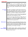
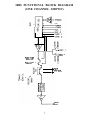
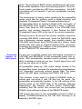
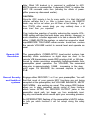
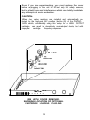
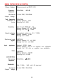
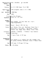
Hafler Iris Preamplifier
It is a good habit to turn down BOTH remote and main
panel volume controls upon system shut-down. This
will avoid possible sudden and unexpected changes in
volume when system is re-activated.
TABLE OF CONTENTS
Introduction .................................................................
Page 1
installation ..................................................................
Page 2
Operation ....................................................................
Page 5
IRIS Block Diagram ....................................................
Page 7
Using the IRIS Remote System
Introduction ...............................................................
Page 10
Operation .................................................................
Page 14
Specifications ...........................................................
Page 16
Warranty ...................................................................
Page 18
INTRODUCTION
Your IRIS preamplifier combines superb, all-discrete, J-FET
amplification stages with unique control methods allowing
unprecedented flexibility and convenience. In this manual,
beyond telling you how to use IRIS, we will try to convey the
spirit and method of how this unusual combination was achieved.
The J-FET devices share many technical and sonic characteristics with the best of vacuum triodes. They also allow things
vacuum tubes don't easily allow, such as high speed and very
low noise.
INSTALLATION
The gloss black insert on the face-plate of your new Hafler
Equipment has been packaged with a removable protective
coating. Please peel off this protective coating following installation.
When cleaning the face-plate, we advise a soft cotton cloth with
a non-abrasive cleaner that is safe for lexan and painted
surfaces. DO NOT use paper towels or any coarse material to
clean the face-plate as these materials may scratch the insert.
IRIS is shipped with styled end caps on its front panel. Rackmounting ears are available from the factory for standard 19”wide racks.
In locating IRIS, keep these factors in mind:
1) All preamplifiers with high-gain moving-coil phono circuitry
can be susceptible to pickup of hum from strong external
magnetic fields. Such fields are usually strongest from power
amplifiers, but can also come from other equipment. When
stacking or racking your equipment, you may have to do so as
to minimize this potential problem.
2) The IR (infrared) “eye” for the IRIS remote system is behind
the dark red screen above the Record 1 switch. The IRIS
remote system combines a powerful transmitter and very
sensitive receiver, resulting in highly reliable communication
under conditions where many remotes will not work. However,
best operation usually results if the preamplifier is located AT or
ABOVE the height at which you will typically use the transmitter.
3) It is also desirable that the IR “eye” not have to look directly
at extremely bright light sources, particularly those of fluorescent nature. Such conditions can impede communication reliability.
2
Power
Connections
IRIS is internally connectable for virtually all AC line-power
systems. Units not marked otherwise, on the rear panel, are
connected for 120 Vofts, 50-60 Hz.
Two SWITCHED outlets and one UNSWITCHED outlet (U.S.
120 Volt standards) are provided on the rear panel. The
UNSWITCHED outlet is provided for powering certain mechanical equipment, if so recommended by its manufacturer.
The SWITCHED outlets can be used for all other devices up to
a total (for all outlets) of 580 Watts (continuous-rating).
The IRIS power switch is very rugged and can sustain the turnon surge of large amplifiers. However, some audio purists
prefer to connect large power amplifiers through alternate linesupply arrangements to minimize any added magnetic fields in
the low-signal environment of their preamplifier.
Input
Connections
and Selection
(Phono)
IRIS employs a very low-noise, high-gain, complementarysymmetry phono circuit of selectable gain, derived from our
U.S. patent 4,496,910. The phono stage output is selected by
the PHONOKEY and then, processed the same as other HIGH
LEVEL inputs.
The phono inputs (gold jacks) are compatible with normal
MOVING-MAGNET and HIGH-OUTPUT MOVING-COIL
cartridges (typically 2-5 mV), and LOW-OUTPUT MOVINGCOIL cartridges (typically 0.2-0.5 mV). Input impedance is 47k
ohms, except when optional cartridge loading is employed.
This is discussed at the end of this manual.
The rear-panel (MM/MC) switch (next to the phono jacks), when
depressed, increases phono-stage gain by 20dB for LOWOUTPUT MOVING-COIL cartridges.
CAUTION:
Never operate this switch, either way, unless the VOLUME
control is turned full down, as the very high gain present can
result in switching transients able to blow fuses in amplifiers or
loudspeakers, or damage some types of loudspeakers.
3
The usual ground thumbscrew is provided for turntable-frame
grounding via the extra ground wire provided on most turntables.
High Level
Inputs
(Oval Key
selected)
IRIS has seven pairs of main HIGH LEVEL inputs, selected by
the seven (oval) KEYS to the right of the phono KEY. All of these
inputs proceed at unity gain to the attenuator/line-amplifier
system, which has a maximum gain of 20dB.
All of these basically identical inputs are selectable by the input
KEY switches. The KEY switches activate a digital system
which effects audio-signal selection by FET switches, followed
by matched J-FET buffers.
Excepting phono, all input impedances, for the entire preamplifier, are in the 15-28k ohms range.
To get you to the basic operation of IRIS as quickly as possible,
we have deferred the discussion of EPL and TAPE loops to a
later section.
Main Outputs
and
Mono switch
The MAIN output jacks are used to feed the power amplifier.
Their low output impedance of 316 ohms allows driving long
cables if necessary.
The MONO switch effects a passive combining of the stereo
channels into monaural, fed through the attenuator system to
both line amplifiers. Although rarely used today, this switch is
provided for the optimum reproduction of treasured mono
recordings, and can be employed to check for exact system
balance.
It is highly recommended that where you may have a constant
monaural source, such as a mono TV, that you secure a “Y”
splitter from an electronics store and feed both preamp channels in parallel. This makes remote operation easier, and
avoids accidentally leaving MONO engaged when you switch
back to a stereo source.
OPERATION
CAUTION:
The EPL switch and the tape MONITOR switches, explained
later, are often the cause of an apparently “dead” system, when
they have accidentally been left engaged. Always check them
first if a system is found “dead” on turn-on. For now, make sure
that all six of the group of round-button switches are in theirOUT
position.
Turn-On/Off
logic
When IRIS is powered-up, the MUTE legend will light alone,
along with a small GREEN indicator, between the knobs, called
the VOLUME/BALANCE (V/B) indicator. The V/B indicator
shows that the IRIS panel knobs are determining VOLUME and
BALANCE. Its operation is explained in the remote section.
During this period, none of your KEY inputs will be accepted into
memory. This period is about five seconds, during which the
MAIN outputs of the preamplifier are muted.
At the end of this turn-on safety period, the MUTE indicator will
go out and the TUNER legend will light. TUNER mode is
designed as a reset state to facilitate easiest turn-on for
background music etc. Any of the other seven inputs may now
be selected by their appropriate KEY.
Muting System The MUTE KEY causes the MUTE light to illuminate, and the
preamp to fade down approximately 20dB. This mode is used
for phono cueing and at any other convenient time, such as
answering a phone etc. Depressing the NORMal KEY restores
normal level. The two-key format is used so that you always
know whether you are muting or de-muting.
Volume/ The level-control system in IRIS is unusual and uniquely suited
Balance System to our goal of combining superb sound with high convenience.
It is an indirect type in which no audio signals are passed
through the panel controls.
The actual audio attenuation elements are passive opticallycontrolled resistors, arranged in a special CYBER-OPTIC
control circuit (patent applications in progress) which allows a
combination of very low distortion and stereo tracking accuracy
(typically 0.1dB) not previously possible in a passive, continuous control system.
The BALANCE control produces approximately 13dB maximum cut in one channel, while boosting the other channel by
3dB-to maintain constant music power during control panning.
The EPL and This simplified signal flow diagram can be very helpful in
Tape Loop understanding the discussion of the EPL and TAPE loops.
Systems
In IRIS, the EPL output jacks and RECORD output jacks are
activated only when the related panel switch is engaged. This
completely disconnects the inputs of unpowered accessoriesoften a cause of distortion. These buffer-fed jacks have 2.15k
ohms output impedance.
The EPL (External-Processing-Loop) system consists of the
EPL switch and the EPL output and EPL input jacks. When the
EPL switch is engaged, you may use the EPL outputs to feed
into an external accessory, and receive its returning output on
the EPL input jacks. You can alternatively employ the EPL input
jacks as an 8th HIGH Level input.
The tape system on IRIS comprises two pairs of TAPE input
jacks, two pairs of RECORD output jacks and six related control
switches.
Note that the TAPE input jacks are selectable either by the input
selector KEYS, or by the tape MONITOR switches. These jacks
receive the OUTPUTS of tape decks.
For PLAYING tapes you will likely prefer to use the tape KEYS
for selection-particularly as these functions are accessible
from the IRIS remote.
The four round buttons associated with tape functions are not
needed for normal tape playback.
6
IRIS FUNCTIONAL BLOCK DIAGRAM
(ONE CHANNEL SHOWN)
bREC
MON I TOR
SWITCH
1
MON I TOR 2
SWITCH
0
e
A
7
0
CUT
IN
EPL
MAIN
OUT
7
2
Recording
System
Any recording requires that you activate either the RECORD 1
jacks, the RECORD 2 jacks (or both) using the RECORD 1 or
RECORD 2 switches on the panel.
As seen in the signal flow diagram, this makes any input
selectable by the KEYS available to these outputs.
EXAMPLE: KEY-selecting TUNERwith RECORD 1 depressed
will send both TUNER channels out the RECORD 1 jacks to the
INPUTS of the tape deck.
The diagram also shows that if you have two decks you can
select either as a PLAYER using the TAPE KEYS and send it
to the other deck for recording.
EXAMPLE: Select deck 1 as PLAYER with TAPE KEY 1 and
send to deck 2 through the RECORD 2 switch and jacks.
1OR: Select deck 2 as PLAYER with TAPE KEY 2 and send to
deck 1 through the RECORD 1 switch and jacks.
CAUTION:
Engaging either RECORD switch on IRlS brings into action
special safety logic which you may easily interpret as faulty
operation, until you understand its put-pose:
1) IRIS refuses TAPE
KEY 1 if RECORD 1 is engaged. Likewise
for TAPE KEY 2 and RECORD 2. These are potentially dangerous sources of unexpected high-energy positive feedback
loops, having been known to destroy more than a few loudspeakers.
2) These switches automatically restrict certain remote control
actions, as explained later.
~Thus always leave these switches OUT, unless actually recording.
Tape
Monitoring
Switches
The tape MONITOR switches at first appear to allow only a
redundant selection of what you hear from your deck(s) when
you use the TAPE KEY(s). The important difference is that
MONITOR switches actually BREAK the audio path inside the
preamplifier, allowing you to listen to the deck’s OUTPUT while
its INPUT is being fed from any source selectable by the KEYS.
This feature is necessary for selectable by the KEYS. This
feature is necessary for real-time monitoring in three-head
decks, but can be of some value for signal-path verification in
two- head decks.
Engaging both tape MONITOR 1 and tape MONITOR 2 switches
results in the selection of tape MONITOR 2.
Make it a habit after recording to check that all six of the round
buttons are back OUT-unless you are using EPL or MONO.
USING THE IRIS
REMOTE SYSTEM
Infrared Remote Integrated System
INTRODUCTION
The IRIS preamplifier achieves its infrared (IR) remote capability by the addition of the IRIS remote RECEIVER board, which
plugs into a keyed male connector at the top of the preamplifier’s
Command/Memory/Display (CMD) board, containing the frontpanel key switches and legend LED's.
IRIS employs a "carrier" of bright IR
IR pulses modulated in
frequency (25/35 kHz) by a 32-bit Pulse-Code-Modulation (PCM)
signal. The carrier is also amplitude modulated for clocking
synchronization. This code must pass stringent format checking at the receiver, to ensure communication security.
The IR pulses radiate from the two clear LEDs arranged in a”V”
formation, protruding through the remote’s bezel. Dominant
radiation is to the front, where the minute lenses are located, but
considerable radiation is available to the sides and rear of the
array. Thus you will likely find that the remote will communicate
well to most preamplifier locations without having to aim the
transmitter-but every room is different in the IR world, so you
should experiment for best results, possibly also re-reading the
preamplifier location recommendations earlier in this manual.
Key Command
Transmissions
The top eight KEYS operate much like the input selector KEYS
on your preamplifier. However, from REMOTE, you must hold
the KEY long enough to get at least one flash from the RED
(Completed-Frame) LED at the top front of the remote. The
bottom KEYS, MUTE and NORMAL, operate similarly. The
remaining two KEYS, CLR and SX are explained later.
volume/
Both of the remote’s knobs are connected to a capacitive touchsensing circuit. Touching either knob ALONE causes the remote
to transmit the position of BOTH knobs to the IRIS receiver. The
process takes approximately 1/8 second. At each successive
1/8 second, a new 32-bit frame of knob-position data is transmitted, tracking your knob-motion-until slightly after you release
the knob.
Balance (V/B)
Command
Transmissions
10
Note: The touching of BOTH knobs simultaneously will sometimes inhibit operation of the touch-sensing system. The knobtouch system overrides any KEY-type command-so that KEY
commands will not transmit, if you are accidentally touching
either knob.
The transmission of analog control positions to the preamplifier
works much like the process used in digital recording and
playback. Duringeachof these 1/8-second transmission frames,
the transmitter takes an Analog-to-Digital (A/D) conversion of
the BALANCE knob position, transmits it twice, in different
forms, then takes an A/D conversion of the VOLUME knob
position, and similarly transmits it, then flashes the RED
(Completed-Frame) LED at the top of the remote transmitter.
During the same 1/8 second, the receiver carefully checks the
incoming BALANCE code-format, loads the BALANCE data
into a temporary storage register, then carefully checks the
VOLUME code-format, and if BOTH pass ALL checks, finally
sends both data sets to Digital-to-Analog (D/A) conversion
overriding the analog DC Voltages of the preamplifier’s knobs
to the CYBER-OPTIC attenuator system.
Automatic
Transfer of
V/B Control
To give you completely natural and safe analog command of
VOLUME and BALANCE at both preamplifier panel and remote, IRIS automatically transfers control authority immediately to whichever knob-set you use. Control stays there until
you use the other set of knobs.
At preamplifier power-up, V/B control always reverse to the
preamplifier’s knobs, because the unpowered preamplifierdoes
not “remember” previously entered remote data. The green
panel V/B LED lights, indicating this PANEL V/B mode.
This indicator is also used in a bright FLASHING mode to
indicate each new arrival of valid V/B data from the remote. The
preamplifier automatically transfers to the V/B settings of the
remote knobs on the FIRST flash of this indicator. After the
transmission, this indicator will then remain UNLIGHTED,
indicating that V/B control has moved from the preamplifier
PANEL knob settings to those of the REMOTE knobs.
V/B control will return to the preamplifier’s knobs if either is
slightly TURNED-indicated by the V/B LED returning to its
statically LIGHTED state.
11
Note: Which V/B knob-set is in command is unaffected by ANY
KEYS-remote or preamplifier. It depends ONLY in where the
LAST V/B command came from (including the effects of preamplifier power-up discussed earlier).
CAUTION:
Since the IRIS remote is fun for many adults, it is likely that small
children will also find it so. After a system turn-on, the REMOTE
knobs may not be set where you left them at last listening. If you
then TOUCH either remote knob, you may suddenly have a lot
more level than you expected!
Your instinctive reaction of quickly reducing the remote VOLUME setting will take this level down very quickly. However, in
such situations, a better approach is to use a remote KEY to
either (-20dB) MUTE the system, or select an unused or dead
input-BEFORE TOUCHING either remote knob then restore
the remote VOLUME control to normal level and operate as
usual.
Remote V/B
Resolution
Record Security
and Umbilical
systems
The preamplifier’s CYBER-OPTIC level-control system has
essentially infinite resolution-as no digital steps are used. In the
remote V/B transmission mode IRIS employs 8-bit or 256-step
format to obtain resolution essentially indistinguishable from
preamplifier panel operation. For VOLUME, the command
step-size is approximately 0.25dB, increasing in the deepcutoff region. For BALANCE, the command step-size is typically
0.1dB.
Engage either RECORD 1 or 2 on your preamplifier. You will
find that most of your remote KEY functions are not being
accepted at the preamplifier, but VOLUME BALANCE, MUTE
AND NORMal are working as usual. This unique IRIS feature
allows you to retain convenient remote control of those functions
which come AFTER the RECORD OUTPUT jacks in the
preamplifier signal path, but keeps you from accidentally inputting any commands which would spoil your recording process.
An INTERRUPTED flashing of the preamplifier’s MUTE indicator tells you which functions it will not accept during this safety
mode.
12
The rear of the IRIS receiver card has a recessed, keyed male
connector which carries needed digital signals for allowing the
IRIS system to be connected to coming Hafler IRIS-compatible
accessories, in a manner similar to which dispersed computer
terminals can share the same data lines without confusion.
The TUNER legend commands already on the remote will
automatically route to the soon coming IRIS-compatible TUNER,
after you have selected TUNER, if it is powered. Similar logic
exists on the CD selection. The CLR (CLeaR) KEY allows you
to return to normal preamplifier input selection.
A STEADY flashing of the MUTE LED tells you that automatic
command out-routing is in effect. If RECORD SECURITY is also
ineffect, the INTERRUPTED flashing will override the STEADY
flashing, telling you that IRIS refuses to enter TUNER (or CD)
changes from the remote, during recording.
sx (Serial
eXternal KEY
This KEY is included to minimize the risk of system obsolescence by allowing for future accessories which may require
more detailed instructions than can be provided by IRIS’ usual
easy single keystroke commands.
You can preview this operation, and also observe the STEADY
MUTE LED flashing discussed above, by KEYing SX and
following with any sequence of the top 8 KEYS depressed within
3 second intervals.
All IRIS-compatible accessories will also have a similar (synchronously) flashing indicator showing when they are RESPONDING to out-routed commands.
Battery
Replacement
The RED (Completed-Frame) indicator, on the transmitter, is
arranged to grow dimmer rapidly, when batteries are approaching end-of-life. Even though the remote will still work, its range
will be less and corrosion could begin to set in-if this condition
is left too long.
Replacement batteries: (4) AA type, preferably Alkaline.
13
1) Remove the 4 screws on the bottom cover of the transmitter,
and pull the cover off.
2) The battery polarities are clearly marked in the plastic holder,
visible when the batteries are removed.
Carefully observing these polarity markings, replace all 4
batteries.
3) Check IMMEDIATELY for normal transmitter operation by
observing the RED transmitter indicator. It should now flash
brightly.
4) Replace the bottom cover, making sure to orient it for the
screw pattern, and replace the 4 screws.
OPTIONAL CARTRIDGE LOADING
Optional cartridge loading is a “fine-turning” matter, and many
cartridges work quite well without it. ONLY a cartridge’s
manufacturer can provide proper recommendations for this
process, as every cartridge is different. And ONLY you can say
for sure whether or not it produces meaningful sonic improvement-for you. For those who wish to change the factory
installed loading, we have included a very flexible system which
automatically switches loading components when MM or MC is
selected.
Your preamplifier has been supplied with 100 ohm resistors and
220 pF capacitors installed in the appropriate sockets. While
these values are suitable for most cartridges, you may wish to
alter them as described below.
InstructionsFor Qualified
Personnel only
The preamplifier must always be UNPLUGGED from AC before
removing its cover. Full AC line voltage is present at numerous
locations inside the unit.
Remove the 4 screws under the unit which securethetopcover,
and slide it off, to the rear. The diagram below shows how to cut,
form and plug-in optional loads. Observe carefully which sockets are for MM (capacitors) and for MC (resistors).
14
Even if you are experimenting, you must replace the cover
before re-plugging in the unit to AC-not only for safety reasons,
but to shield hum and interference which can totally invalidate
any attempts at sonic evaluation.
CAUTION:
When low value resistors are installed and automatically selected by the high-gain MC position (button IN) of the PHONOGAIN switch, accidentally using this setup for a HIGH OUTPUT
cartridge can result in deceptively normaloutput levels, but with
improper
cartridge
frequency-response.
MC
RES
I STOR
CAPACITOR
1tt11.
II
88 0
0
bflrr
IRIS
0
0
0
0
IRIS WITH COVER REMOVED.
SHOWING LOCATION OF OPTIONAL
CARTRIDGE LOADING PLUG-INS.
15
IRIS SPECIFICATIONS
Phono Section:
Output
(Measurements at REC OUT)
Frequency
Response:
20Hz-20kHz,
Maximum
Voltage:
5 Volts RMS, 20Hz-20kHz
Totul Harmonic
Distortion &
Noise
Sensitivity:
±0.1 dB
20Hz-20kHz
Moving Magnet: .002%
Moving Coil: .009%
(For 0.5 volts RMS @ 1 kHz
Moving Magnet: 6.0 mV RMS
Moving Coil: 600 p V RMS
Signal to Noise
Ratio:
(A-weighted, relative to 0.5 V RMS)
Moving Magnet: -87dB
Moving Coil: -8OdB
Maximum Input
Signal:
(@1kHz)
Moving Magnet: 65 mV RMS
Moving Coil: 6.5 mV RMS
Input
Impedance:
Gain:
LINE SECTION
Frequency
Response:
Bandwidth:
Output
Maximum
Voltage:
Nominal 47,000 ohms
Moving Magnet: 220 pF as supplied, user adjustable
Moving Coil: 100 ohm as supplied, user adjustable
(@1kHz)
Moving Magnet: +38.5dB
Moving Coil: +58.5dB
20Hz-20kHz,
6Hz- 1 50kHz,
$0.1 dB
-3dB, into 1 Ok ohm load
8 volts RMS, 20Hz-20kHz
16
.005%, 20Hz-20kHz
Total Harmonic
Distortion &
Noise:
Sensitivity:
(For 0.5 V RMS Output): 75 mV RMS
Signal to Noise
Input
@ 2 volts RMS
-97dB (A-weighted, relative to 2.0 V RMS)
Ratio:
Impedance:
15-28k Ohms
+20dB
Gain:
I
Output
Impedance:
GENERAL
Inputs
Line Out: 316 ohms
Record Out: 2150 ohms
Phono (Mv/MM), CD, Tuner, Video, Aux 1, Aux 2,
Tape 1,Tape 2,EPL In
Outputs:
Record 1, Record 2, EPL Out, Line
Controls:
input Selectors, Phono gain, Mute/Normal, Record Send 1,
Record Send 2, Tape Monitor 1, Tape Monitor 2, External
Processor Loop engage, Mono, Balance, Volume, Power
convenience
(Polarized) 1 Unswitched,
Outlets: 72 amp surge
Size:
TRANSMITTER
Controls:
Size:
Batteries:
2 Switched, 5 amp continuous,
17” wide x 3” high x 8 1/2” deep
Input Selectors (or as redefined when IRIS compatible unit(s)
are present), SX/Clear, Mute/Normal, Volume & Balance Knobs
2 7/8” wide, 11 1/2” high, 7 1/2” long
4 x AA Alkaline
17
FACTORY SERVICE AND LIMITED WARRANTY
If you encounter anydifficultyor have anyquestionsconcerning
your IRIS preamplifier, please call our Customer Service Department weekdays, 8 am to 3:30 pm Mountain Standard time,
at 602-967-3565.
Before returning any unit to the factory for service, please call
us. All units being returned (regardless of warranty status) must
receive a Return Authorization (RA) Number. In addition, we
can offer trouble-shooting assistance that may often simplify or
even eliminate the need for factory service.
The Hafler IRIS is warranted for 3 years from date of purchase,
including parts, labor, and return shipping costs from the factory
to the owner within the Continental USA.
It is the owner’s responsibility to pay shipping (preferably UPS)
to the factory: collect shipments will not be accepted. Units
under warranty should be accompanied by a copy of a dated Bill
Of Sale. Use the original carton and all packing material, and be
sure to include a return address, and a brief description of the
difficulty, including whether it is intermittent.
This warranty gives you specific legal rights. You may also have
other rights which vary from state to state.
18