1
Alice A I R 2 0 0 0 U s e r M a n u a l
THE CONCEPT
The ALICE AIR 2000 Broadcast mixer is designed specifically for rigorous use by
professional broadcasters. Over three years of research and development, together
with extensive consultation with engineers and presenters at a large number of radio
stations world wide, have resulted in numerous features not normally available
without expensive customisation, or external ‘black boxes’.
The AIR 2000 has been designed to require minimum maintenance and to provide
excellent reliability for many years of hard service. All component parts have been
carefully selected to ensure that their life expectancy is no less than that appropriate
for the job. Only high quality conductive plastic faders are used. High quality VCA's
remove audio signals from channel faders maximising their life, eliminating
'scratching' and ensuring tight stereo tracking.
Headphone and speaker controls, normally notorious for early failure, employ the
same VCA technology, together with DC control derived from paralleled
potentiometers for maximum reliability.
All ICs are fitted in gold plated, turned pin holders for ease of servicing and reliable
contact. Two part, gold plated locking, module connectors eliminate unreliable edge
connectors. All illumination is achieved by high brightness LED clusters, eliminating
bulb failures. Large heavy duty, high quality switches are provided for main functions
and the result is a mixing console on which we are confident to offer an ten-year
limited warranty.
A blank sheet approach to circuit design has resulted in many innovative circuitry
developments, which extensively overcome previous shortcomings in commonly
used circuit configurations.
A totally new electronic floating balanced output stage gives a ‘ruler flat’ frequency
response and a full 28dB wide band headroom performance unbeaten by even the
best transformer based outputs. This proprietary design achieves an output
impedance of less than 1 ohm, uniquely guaranteeing constant output level into
balanced or unbalanced loads, irrespective of their impedance. In comparison, a
typical 75 ohm output would suffer a gain error of over 1 dB and commonly also
results in changes to the frequency response when the load is changed from high
impedance bridging to 600 ohms.
Many active balanced outputs do not allow unbalanced connection without causing
considerable gain error and/or gross distortion and in some cases may even damage
the shorted output driver. Others which attempt to overcome these problems are
prone to instability when driving long lines, still give unbalanced gain errors of around
0.2dB and rely on sensitive adjustment pots to achieve acceptable output balance.
Naturally, these tend to drift with time and result in additional maintenance work for
the already overstretched engineer. With no fewer than 8 balanced output stages on
the main output module and others on insert points and telephone sends, the total
elimination of output balance adjustment pots is a major advantage.
interstage
Phistersvej 31, 2900 Hellerup, Danmark
Telefon 3946 0000, fax 3946 0040
www.interstage.dk
- pro audio with a smile
A unique pan pot design ensures perfect centre balance and provides 25-3OdB
better final attenuation than conventional designs. New level control and EQ circuitry
utilising centre-tapped pots and zero impedance buffers forces predictable
performance, irrespective of pot tolerances, ensuring outstanding stereo tracking.
Mix busses are differentially balanced for improved crosstalk performance, rejection
of unwanted interference and ground loops. Totally silent solid state audio switching
completely removes inactive input channels from the mix busses, preventing
unnecessary build up of mix noise and providing virtually unmeasurable inter-channel
crosstalk.
DUAL MICROPHONE INPUT - Two separate, state of the art mic pre-amps give
individual gain preset and phantom power for different microphone configurations.
Remote control of channel ON, OFF, COUGH, & REVERSE TALKBACK is steered
through the A/B switch to allow connection of illuminated remote buttons at the
selected microphone position. Loudspeaker muting and on- air lights are separately
programmable between control room and studio.
DUAL STEREO LINE INPUT - Two electronically floating balanced stereo inputs,
with individual gain preset accept signals from varying sources, including domestic
equipment, without additional level matching interfaces. Remote switching is steered
through the A/B input select switch and steady state or pulsed control outputs may be
programmed separately for each input. Left and right buttons allow either the left or
right channel to be directed to the stereo output, (selecting both switches the channel
to mono).
MACHINE & MICROPHONE TIMERS - are fitted as standard, and a further optional
timer unit can be fitted to all but the smallest frames for use with the off air record
mix.
METERING - Three PPM meters are fitted as standard (VU meters are available to
special order). The metering is configured so that the stereo meters show PGM
output and the mono meter follows the source selected on the Control Room monitor
module and overridden by CUE. Additional meter modules may be fitted to mixer
frames (space permitting) to monitor REC, AUX and MONITOR outputs - these can
be ordered with the mixer or easily user-fitted later.
PFL/CUE may be jumper selected to automatically cancel when channels are put to
air, allowing easy junctioning into network feeds and preventing accidental cueing of
open channels.
LOGIC Opto isolated start/stop outputs allow connection to almost any logic levels,
virtually eliminating the need for engineers' 'black boxes' to interface differing makes
of studio equipment. The A and B inputs are separately programmable with either
steady state or pulse signals to allow for dissimilar machine start/stop requirements,
even on the same channel. Provision is made for control of start/stop logic functions
by external remote control buttons. Microphone channels can also be remote
controlled with external remote button provision for ON, OFF, COUGH and
REVERSE TALKBACK to operator. This extensive remote control can allow a
newsreader at a remote position to play in his carts
interstage
Phistersvej 31, 2900 Hellerup, Danmark
Telefon 3946 0000, fax 3946 0040
www.interstage.dk
- pro audio with a smile
FRONT PANEL CONTROLS
DUAL INPUT STEREO LINE MODULE (2002/2102)
GENERAL
The dual input stereo line module is designed to accept stereo or mono line level
inputs. Non standard levels are allowed for by means of internal pre-sets, with a gain
range of -10dB to +20dB, with reference to the normal unity gain setting. The A & B
inputs may be lined up separately allowing normal professional line levels on one
input, whilst low level domestic equipment may be used on the other input.
Logic control is extremely flexible, and may be programmed independently for each
input. Start and stop commands are fully opto-isolated, allowing almost any external
machine logic to be interfaced without the need for custom black boxes.
Controls have been kept simple and uncluttered so as to allow self-operation by
relatively non-technical staff. Large illuminated push buttons are provided for major
functions.
TRIM
Allows +/- 10dB gain adjustment. The pot has a centre detent to allow easy location
of 'unity gain' position.
INPUT SELECT
Selects between the “A” and “B” stereo line inputs and also steers the programmable
control logic to the appropriate machine. Separate high brightness LED’s are situated
adjacent to the A/B switch to give clear indication of which input is selected.
LEFT/RIGHT/MONO
The LEFT button routes the left leg of the input signal to both sides of the channel
output. The RIGHT button routes the right leg of the input signal to both sides of the
channel output. Selecting both LEFT and RIGHT buttons together will mono the
input.
OPTIONAL EQ SECTION
Provides 15dB boost or cut at 60Hz (IF) and 12kHz (HF) with a shelving
characteristic, and 15dB boost or cut at 1 kHz (MF) with a Bell characteristic and a
"Q" (bandwidth factor) of 1.5. Centre detents allow for easy location of the flat
position. An EQ in/out switch with LED indication is provided.
OUTPUT SELECT
The REC button diverts the main channel output to the off-line record mix. It also
routes the channel's clean feed outputs to the off-line clean feed busses producing
an appropriate feed for any telco channels that are similarly routed to the REC mix
rather than the main PGM mix. This therefore allows completely independent off-line
stereo production and recording to-take place whilst the mixer is on-air.
AUX
The AUX button selects the channel output to the aux. mix, providing a convenient
method of generating an additional stereo clean feed for effects, studio foldback and
reverse cue for remote broadcasts.
BALANCE
± 3dB of adjustment is provided to allow for stereo imbalance on programme material
or for effect. A centre detent allows easy location of the calibrated position.
CUE
Cue mode is activated on and off by successive presses of the button. Indication of
cue is provided by high brightness LED illumination of the switch. Various auto-reset
functions can be programmed to suit user requirements. Cue is derived after the
balance pot, but before the channel's stereo VCA section. This allows the balance
pot to be set up whilst in cue ('stereo in place cueing'). Please refer to logic preprogramming section.
FADER
A high quality conductive plastic 104mm unit is fitted. The fader controls a DC
voltage, which in turn controls the channel VCA’s and provides bottom of track
switching functions for logic control and final audio muting.
FADER START
Enables fader start facility for machine control. Opening the fader then becomes
equivalent to simultaneously pressing the ON button and closing the fader becomes
equivalent to simultaneously pressing the OFF button.
ON / OFF
Please refer to logic pre-programming section.
DUAL INPUT MICROPHONE MODULE (2001/2101)
GENERAL
The dual input microphone module features two, separate, state of the art,
transformerless pre-amplifiers with a noise figure, at full gain, within 0.5dB of
theoretical limits and a common mode rejection typically better than 1 OODB.
Individually adjustable internal pre-sets allow for differing microphone types and
working distances at the A and B mic positions. Gain is adjustable in the range of 4OdB to -7OdB, with a further +/- 10dB gain available from the front panel trim pot,
giving a total range of -3OdB to -8OdB. High level audio switching after the pre-amps
prevents switch clicks.
The comprehensive logic control may be programmed independently for each input.
Remote control of ON, OFF, COUGH and REVERSE TALKBACK commands are
available together with LED drivers for remote button illumination. These are
automatically steered to and from the appropriate mic position via the A/B switch.
Controls have been kept simple and uncluttered so as to allow self-operation by
relatively non-technical staff. Large illuminated push buttons are provided for major
functions.
TRIM
Allows +/- 10dB gain adjustment. The pot gives continuous gain adjustment, whilst
maintaining maximum headroom at all gain positions.
INPUT SELECT
Selects between the A or B mic inputs and also steers the programmable control
logic to and from the appropriate mic position, Separate high brightness LED’s are
situated adjacent to the A/B switch to give clear indication of which input is selected.
OPTIONAL EQ SECTION
Provides 15dB boost or cut at 60Hz (LF) and 12kHz (HF) with a shelving
characteristic, and 15dB boost or cut tuneable from 700Hz to 1OkHz with a bell
characteristic and a "Q' (bandwidth factor) of 1.5. Centre detents allow for easy
location of the flat position. An EQ in/out switch with LED indication is provided.
OUTPUT SELECT
The REC button diverts the main channel output to the off-line record mix. It also
routes the channel's clean feed outputs to the off-line clean feed busses producing
an appropriate feed for any telco channels that are similarly routed to the REC mix
rather than the main PGM mix. This therefore allows completely independent off-line
stereo production and recording to take place whilst the mixer is on-air.
AUX
The AUX button selects the channel output to the aux-mix, providing a convenient
method of generating an additional stereo clean feed for effects, studio foldback and
reverse cue for remote broadcasts.
PAN
Allows the channel output to be placed at any point within the stereo image. The
detented centre position presents a loss of 3dB giving a substantially constant sound
level no matter where the signal is positioned within the stereo image.
CUE
Cue mode is activated on and off by successive presses of the button. Indication of
cue is provided by high brightness LED illumination of the switch. Various auto-reset
functions can be programmed to suit user requirements. Cue is derived after the pan
pot but before the channel's stereo VCA section. This allows the pan pot to be set up
whilst in cue ('stereo in place cueing'). Please refer to logic pre- programming
section.
FADER
A high quality conductive plastic 104mm unit is fitted. The fader controls a DC
voltage, which in turn controls the channel VCA’s and provides bottom of track
switching functions for logic control and final audio muting.
ON / OFF
Please refer to logic pre-programming section.
TELCO INPUT MODULE (2003)
GENERAL
The Telco input module is designed to allow the connection of phone-in lines via an
external telephone hybrid. Many hybrids incorporate a changeover relay between a
normal telephone instrument and the hybrid line connection. This can be remote
operated from the channel.
Controls have been kept simple and uncluttered so as to allow self-operation by
relatively non-technical staff. Large illuminated push buttons are provided for major
functions.
TRIM
Allows +/- 10dB gain adjustment. The pot has a centre detent to allow easy location
of ‘unity gain’ position.
HOLD
Produces the necessary signal for telephone hybrids that incorporate a changeover
function between the normal telephone handset and the channel input.
OUTPUT SELECT
The REC button diverts the main channel output to the off-line record mix. This
therefore allows completely independent off-line stereo production and recording to
take place whilst the mixer is on-air.
AUX
The AUX button selects the channel output to the aux-mix, providing a convenient
method of generating an additional stereo clean feed for effects, studio foldback and
reverse cue for remote broadcasts.
PAN
Allows the channel output to be placed at any point within the stereo image. The
detented centre position presents a loss of 3dB which gives a substantially constant
sound level no matter where the signal is positioned within the stereo image.
CUE
Cue mode is activated on and off by successive presses of the button. Indication of
cue is provided by high brightness LED illumination of the switch. Various auto-reset
functions can be programmed to suit user requirements. Cue is derived after the pan
pot but before the channel's stereo VCA section. This allows the pan pot to be set up
whilst in cue ('stereo in place cueing'). Please refer to logic pre- programming
section.
FADER
A high quality conductive plastic 104mm unit is fitted. The fader controls a DC
voltage, which in turn controls the channel VCA’s and provides bottom of track
switching functions for logic control and final audio muting.
CONTROL ROOM MONITOR MODULE (2007)
GENERAL
The control room is normally defined as the room in which the desk is situated. The
module controls allow the operator to select which source the control room speakers,
headphones and metering follow.
SWITCHES 1 to 5 are provided for user definable sources such as other studios,
external lines, or tape machine return feeds.
AIR allows for the connection of a receiver for off-air monitoring.
PGM allows for the direct monitoring of the main stereo programme mix.
REC allows for the direct monitoring of the off line record mix.
AUX allows for the direct monitoring of the aux mix.
(N.B. The REC selection carries PGM monitoring as its default setting; therefore if
there are no channels selected to REC its output mimics the PGM bus).
METER SELECT SWITCHES
Allows the operator to select which source the desk's metering follows. Metering can
follow the control monitor selection directly, or can be selected to follow the PGM,
REC, or AUX mixes.
GUEST PHONES
Separate level control for guest headphones, which are not interrupted by cue or
talkback.
CONTROL PHONES
Separate level control for operator's headphones.
CUE TO SPEAKERS
Allows Cue to be sent to the control room monitor speakers. Without this facility
selected the speakers will continue to follow the control room monitor selection.
STEREO CUE
This control allows full stereo cue to be heard on the operator's headphones (and, if
CUE TO SPEAKERS is engaged, on the control room monitor speakers), whenever
an input module is put into cue mode. Without STEREO CUE selected, split cue is
heard, mono cue being fed to the left side and a dimmed, mono programme (as
selected by the source selection switches) to the right.
CONTROL SPEAKERS
VCA controlled level pot for monitor speakers.
DIM
Dims monitor speakers by a fixed 2OdB thus avoiding the need to change the control
room monitor pot from the preferred setting.
MONO
This control switches the monitor speakers and operator's headphones into mono for
phase compatibility checks.
STUDIO MONITOR MODULE (2005)
GENERAL
The studio is normally defined as a remote talks studio or news booth. The bank of
switches allows the operator to select which source the studio monitor speakers and
headphones follow.
SWITCHES 1 to 5 are provided for user definable sources such as other studios,
external lines, or tape machine return feeds.
AIR allows monitoring of the station's off-air signal from a receiver.
PGM allows for the direct monitoring of the main stereo programme mix.
REC allows for the direct monitoring of the off line record mix.
AUX allows for the direct monitoring of the aux mix.
(N.B. The REC selection carries PGM monitoring as its default setting; therefore if
there are no channels selected to REC its output mimics the PGM bus).
GUEST PHONES
Separate level control for guest headphones, which are not interrupted by cue, but
can be interrupted by talkback from the operator.
HOST PHONES
Separate level control for the host's headphones, which are not interrupted by cue,
but can be interrupted by talkback from the operator.
AUX F/B
This switch allows the aux mix to be fed directly to the studio speakers and overrides
the normal microphone mute functions. This allows a selection of sources to be
derived and fed to speakers and is intended for production use.
STUDIO SPEAKERS
VCA controlled level pot for monitor speakers.
STUDIO TALKBACK
Talkback to studio speakers, and by pre-selecting the appropriate buttons, to either
or both the HOST and GUEST headphones, is provided by depressing the TALK
button. During live mic situations, when the speakers are muted, talkback can still be
sent to either or both the HOST and GUEST headphones.
OUTPUT & ON AIR CONTROL MODULE (2006/2007)
Three large non latching push buttons are fitted at the top of the module for
connection to the ALICE AIRSWITCH studio switching matrix, controlling the
switching of up to three studios to air on an 'offer/accept' basis, and to control the
station's profanity delay equipment. The buttons feature high brightness LED
illumination and are marked:
ON AIR
OFFER
DELAY
A further 5 unmarked non latching switches, also with LED illumination are fitted to
allow for user definable status and transmitter alarms. Momentary switches are fitted
to allow for accept or reset functions.
DUMP instructs delay unit, if fitted, to dump delay and return to real time, thereby
removing any unwanted programme material contained within the delay period.
Jumper selects are available on the telco modules to automatically reset the channel
to OFF when dump button is pressed, ensuring that an offending caller having
already been edited is not left live to air.
DUAL INPUT SELECTOR MODULE
This module provides dual selection of eight stereo signals into one stereo output.
Typical applications include use as a line pre-selector ahead of input modules,
allowing selection of several remote outside audio sources. Two banks of switches
are provided each fed with identical sources. This allows cross fading between
sources when connected to two stereo input modules.
TAPE REMOTE MODULE (2009)
Up to three machines may be remotely operated via this module. All switches may be
illuminated for status indication.
TALKBACK MODULE (2010)
This module allows the AIR 2000 to be linked to an ALICE TLK-10 talkback system,
designed for instant communication between studios, newsrooms and other areas.
10 push to talk buttons allow selection of individual destinations as well as a 'talk to
all' facility. The buttons illuminate to indicate the source of incoming talkback.
LOGIC PROGRAMMING & AUDIO LEVEL
DUAL INPUT STEREO LINE MODULE (2002/2102)
AUDIO LEVEL PRE-SET CONTROLS
"A" INPUT
RV1 (marked 'LA’) pre-sets the LEFT channel input gain
RV6 (marked 'RA') pre-sets the RIGHT channel input gain
"B" INPUT
RV2 (marked 'LB') pre-sets the LEFT channel input gain
RV7 (marked 'RB') pre-sets the RIGHT channel input gain
The controls above allow the user to compensate for domestic level equipment being
connected directly to the channel and eliminates the need for interface equipment.
LOGIC OPTIONS
CUE RESET
It is possible to pre-programme three alternative methods of resetting from cue to
normal monitoring. LINK 1 (marked “cue reset”) controls the options.
1. Link set to 'A': Cue will reset when the channel is ON and the fader then opened.
Cue mode can therefore only be selected if fader is closed, or channel is OFF with
the fader open.
2. Link set to 'B': Cue will reset when the channel is either ON or OFF and the fader
is then opened. Cue mode can therefore only be selected with fader closed.
3. Link Removed: Cue mode can be selected or deselected via front panel switch
regardless of channel status.
N.B. With either option 1 or 2 the operator is prevented from selecting “cue" if the
fader is open thus preventing accidental cueing of open channels.
TIMER
SW11 (marked "TIM A"). INPUT A SELECTED. With this switch in the ON position
the machine timer will reset and automatically begin counting up when the front panel
ON switch is pressed with the fader opened; or when the fader is opened with "fader
start” selected. (With this switch in the OFF position the timer will ignore all
operations.)
SW11 (marked "TIM B") INPUT B SELECTED. As above for B input.
STOP/START
SW11 (marked “STDY A"). With this switch selected to OFF, a pulse will be sent to
the ‘A’ input opto each time the front panel channel ON button is pressed, regardless
of whether the channel fader is open or closed. (To allow remote starting of machines
whilst channel is in cue mode.) With SW11 selected to ON the ‘A’ input opto will
directly mimic the front panel ON button, producing a steady-state signal when the
channel is ON. Similarly, when the FADER START button is selected, either a pulse
or steady signal (as selected above) will be sent to the appropriate machine when the
fader is opened.
SW11 (marked “STDY B") works exactly as above for the ‘B’ input.
LINK 2 (marked “OFF RDY") controls the operation of the OFF button on the front
panel. In position ‘A’ the front panel button will operate and indicate normally allowing
the operator to turn the channel OFF.
In the B position the channel OFF function can also be made to work in conjunction
with an outside OFF signal source. The OFF switch used to stop the machine and
the OFF lamp can then be used to indicate a machine's readiness to start. (Certain
machines produce a flashing 'ready" indication which the OFF button will mimic)
LINK 3 (marked 'OFF RDY') works exactly as above for the ‘B’ input.
The following additional pre-set controls will be found on the board. They are all
factory pre-set controls and should therefore not be adjusted.
RV8 (marked “DIST R") is the VCA distortion trim for the right channel audio
path.
RV5 (marked “DIST L”) is the VCA distortion trim for the left channel audio path.
RV9 (marked "VCA GAIN”) fine tunes the VCA gain pre the fader.
DUAL INPUT MICROPHONE MODULE (2002/2102)
AUDIO LEVEL PRE-SET CONTROLS
“A” INPUT
RV1 pre-sets the channel input gain
“B” INPUT
RV2 pre-sets the LEFT channel input gain
The controls above provide a coarse gain pre-set to compensate for differing makes
of microphone and user techniques. The front panel trim provides an additional 10dB
of fine control.
LOGIC OPTIONS
Cue Reset
It is possible to pre-programme three alternative methods of resetting from cue to
normal monitoring. LINK 3 controls the options.
1. Link set to “A”: Cue will reset when the channel is ON and the fader then opened.
Cue mode can therefore only be selected if fader is closed, or channel is OFF with
the fader open.
2. Link set to “B”: Cue will reset when the channel is either ON or OFF and the fader
is then opened. Cue mode can therefore only be selected with fader closed.
3. Link Removed: Cue mode can be selected or deselected via front panel switch
regardless of channel status.
N.B. With either option 1 or 2 the operator is prevented from selecting “cue” if the
fader is open thus preventing accidental cueing of open channels.
LOUDSPEAKER MUTE / RED LIGHT
SW8 Controls the following options:
SW8 (1): When selected to ON, the CONTROL ROOM speaker output will be muted
and the CONTROL ROOM RED LIGHT output activated when the A input
microphone is live.
SW8 (2): When selected to ON, the CONTROL ROOM speaker output will be muted
and the CONTROL ROOM RED LIGHT output activated when the B input
microphone is live.
SW8 (3). When selected to ON, the STUDIO speaker output will be muted and the
STUDIO RED LIGHT output activated when the ‘A’ input microphone is live.
SW8 (4). When selected to ON, the STUDIO speaker output will be muted and the
STUDIO RED LIGHT output activated when the ‘B’ input microphone is live.
N.B. The CONTROL ROOM is defined as the room in which the mixer is installed
and the STUDIO is defined as an adjacent room.
48V PHANTOM POWER
LINK 1 activates the 48V phantom power supply to the A microphone input when set
to the B position.
LINK 2 activates the 48V phantom power supply to the B microphone input when set
to the B position.
The following additional pre-set controls will be found on the board. They are all
factory pre-set controls and should therefore not be adjusted.
RV11 is the VCA distortion trim for the right channel audio path.
RV12 is the VCA distortion trim for the left channel audio -path.
RV4 fine tunes the VCA gain pre the fader.
TELCO INPUT MODULE (2003)
AUDIO LEVEL PRE-SET CONTROLS
RVI pre-sets the channel input gain.
LINK 1 (marked “Filter”): Set to the A position, the internal bandpass filter will be
activated, filtering out unwanted signals below 300Hz and above 3kHz. Set to the B
position the module will operate with the normal "flat" frequency response.
LOGIC OPTIONS
Cue Reset
It is possible to pre-programme three alternative methods of resetting from cue to
normal monitoring. LINK 2 (marked "cue") controls the options.
1. Link set to ”A”: Cue will reset when the channel is ON and the fader then opened.
Cue mode can therefore only be selected if fader is closed, or channel is OFF with
the fader open.
2. Link set to “B”: Cue will reset when the channel is either ON or OFF and the fader
is then opened. Cue mode can therefore only be selected with fader closed.
3. Link Removed: Cue mode can be selected or deselected via front panel switch
regardless of channel status.
N.B. With either option 1 or 2 the operator is prevented from selecting “cue” if the
fader is open thus preventing accidental cueing of open channels.
SW8 (1) Controls the options for use with a profanity delay unit. Set to the OFF
position, the channel will switch to OFF when the DUMP button is pressed, thereby
removing the channel from air but keeping the call on hold. Set to the ON position,
the channel will both switch OFF and drop the line hold when the DUMP button is
pressed.
SW8 (2) When set to ON the front panel HOLD button is defeated. This allows
interfacing to certain makes of telephone systems.
SW8 (3) When set to ON this switch allows a caller to hear the presenter, via the
talkback microphone, when the caller is on hold and the channel is in cue.
SW8 (4) Allows the telco channel to be assigned to the MIC TIMER when set to the
ON position, the MIC TIMER will reset and count when the channel is ON and the
fader opened, or the channel is switched on with the fader already open.
The following additional pre-set controls will be found on the board. They are all
factory pre-set controls and should therefore not be adjusted.
RV4 is the VCA distortion trim for the right channel audio path.
RV5 is the VCA distortion trim for the left channel audio path.
RV7 fine tunes the VCA gain pre the fader.
OUTPUT ‘On-AIR’ MODULE (2006)
This module has a single link, which controls the way in which the OFF-LINE
RECORD bus works. With the link in position “A” the output of the record bus will
follow that of the main programme bus when none of the input channels are diverted
to it. Once an input module is diverted to the bus (via the front panel switch) the bus
only carries the output of those channels diverted to it.
With the link selected to position “B” the off-line record bus only carries the output of
those channels selected to it. Therefore if no channels are diverted to the bus there
will be no output.
TALKBACK MODULE (2010)
This module has a single link which in position “A” activates the control-room red light
when talkback is operated form the control room. This position also prevents talkback
from being heard in the presenter's headphones when any microphones are “live”.
In position “B” operation of talkback does not operate the control-room red light and
incoming talkback will interrupt the presenter's headphones when microphones are
“live”.
CONTROL ROOM MONITOR (2007)
This module has a single link which in the “A” position will give a mono cue on the
mono meter (the stereo meters will continue to show programme output during cue).
In position “B” cue will be presented on the left and right meters in stereo. (The mono
meter will continue to show a mono of programme output during cue)
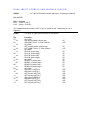
DUAL INPUT STEREO LINE MODULE (2002R)
AUDIO
2 x 3 pin XLR female sockets per input - 2 inputs per channel
BALANCED
Pin 1 – Screen
Pin 2 – Audio + (HOT)
Pin 3 – Audio - (COLD)
(For unbalanced use connect 'HOT' to pin 2, screen to pin 1 and link pins 1 & 3
together)
LOGIC
- 25 Way 'D' type female socket on rear panel
Pin
01
.... 14
02
.... 15
03
.... 16
04
.... 17
05
.... 18
06
.... 19
07
.... 20
08
.... 21
09
.... 22
10
.... 23
11
.... 24
12
.... 25
13
Function
0v LOGIC
ON remote switch (active low)
ON LAMP TALLY (1 2Vdc 3OmA)
0v LOGIC
OFF remote switch (active low)
OFF LAMP TALLY (1 2Vdc 3OmA)
0v LOGIC
PLAY A (active low)
PLAY A (active high)
PLAY B (active low)
PLAY B (active high)
0v LOGIC
READY A (active low)
READY A (active high)
READY B (active low)
READY B (active high)
0v LOGIC
ON input A (OPTO+)
ON input A (OPTO-)
OFF input A (OPTO+)
OFF input A (OPTO-)
ON input B (OPTO+)
ON input B (OPTO-)
OFF input B (OPTO+)
OFF input B (OPTO-)
I/P
0/P
I/P
0/P
I/P
I/P
I/P
I/P
I/P
I/P
I/P
I/P
I/P
O/P
O/P
O/P
O/P
O/P
O/P
O/P
O/P
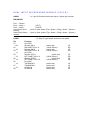
DUAL INPUT MICROPHONE MODULE (2001 R)
AUDIO
1 x 3 pin XLR female socket per input, 2 inputs per channel.
BALANCED
Pin 1 – Screen
Pin 2 – Audio +
Pin 3 – Audio Insert Point Send
screen)
Insert Point Return
screen)
LOGIC
Pin
01
.... 09
02
.... 10
03
.... 11
04
.... 12
05
.... 13
06
.... 14
07
.... 15
08
('HOT')
(‘COLD’)
3 pole ‘A’ jack socket (Tip = Audio +; Ring = Audio -; Sleeve =
3 pole ‘A’ jack socket (Tip = Audio +; Ring = Audio -; Sleeve =
- 15 Way 'D' type female socket on rear panel
Function
0v LOGIC
Remote ON A
ON LAMP TALLY A
Remote ON B
ON LAMP TALLY B
0v LOGIC
Remote OFF A
OFF LAMP TALLY A
Remote OFF B
OFF LAMP TALLY B
0v LOGIC
TALKBACK A
TALKBACK B
COUGH A
COUGH B
(active low)
(12Vdc 3OmA)
(active low)
(12Vdc 3OmA)
I/P
0/P
I/P
0/P
(active low)
(12Vdc 3OmA)
(active low)
(12Vdc 3OmA)
I/P
0/P
I/P
0/P
(active low)
(active low)
(active low)
(active low)
I/P
I/P
I/P
I/P
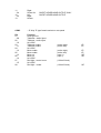
TELCO MODULE (2003R)
AUDIO
SEND
RETURN
(to hybrid) 3 PIN XLR Male
(from hybrid) 3 PIN XLR Female
BALANCED
Pin 1 – Screen
Pin 2 – Audio +(HOT)
Pin 3 – Audio - (COLD)
(For unbalanced use connect 'HOT' to pin 2, Screen to pin 1 and link pins 1 & 3
together)
LOGIC
- 15 Way 'D' type female socket on rear panel
Pin
01
.... 09
02
.... 10
03
.... 11
04
.... 12
05
.... 13
(constant)
06
(constant)
.... 14
07
.... 15
08
Function
0v LOGIC
ON remote
ON LAMP TALLY
0v LOGIC
OFF remote
OFF LAMP TALLY
0v LOGIC
HOLD
0v LOGIC
EXT LINE HOLD
(active low)
(12Vdc 3OmA)
I/P
0/P
(active low)
(12Vdc 3OmA)
I/P
0/P
(active low)
I/P
(active low)
I/P
EXT LINE HOLD
(active high)
I/P
N/C
LINE HOLD
LINE HOLD
N/C
(OPTO+)
(OPTO-)
0/P
0/P
CONTROL ROOM MONITOR MODULE (2007R)
CON1
25 Way 'D' type male connector on rear panel
Pin
01
…14
02
…15
03
…16
04
…17
05
…18
06
…19
07
…20
08
…21
09
…22
10
…23
11
…24
12
…25
13
Function
Screen
+ audio
‘Definable input 1’ LEFT
- audio
Screen
+ audio
‘Definable input 2’ LEFT
- audio
Screen
+ audio
‘Definable input 3’ LEFT
- audio
Screen
+ audio
‘Definable input 4’ LEFT
- audio
Screen
+ audio
‘Definable input 5’ LEFT
- audio
Screen
+ audio
‘AIR’ LEFT
- audio
Screen
Left
Control Room Monitor Speakers Output (unbalanced)
Right
Screen
Cue/incoming talkback Output (muted by CR Red Light) (unbalanced)
Screen
N/C
CON2
- 25 Way 'D' type male connector on rear panel
Pin
01
…14
02
…15
03
…16
04
…17
05
…18
06
…19
07
…20
08
…21
09
…22
10
…23
Function
Screen
+audio
- audio
Screen
+ audio
- audio
Screen
+ audio
- audio
Screen
+ audio
- audio
Screen
+ audio
- audio
Screen
+ audio
- audio
Screen for
Left
‘Definable input’ RIGHT
‘Definable input 2’ RIGHT
‘Definable input 3’ RIGHT
‘Definable input 4’ RIGHT
‘Definable input 5’ RIGHT
‘AIR’ RIGHT
CONTROL ROOM HEADPHONE OUTPUT ONLY
CONTROL HEADPHONE OUTPUT
11
…24
12
…25
13
Right
Screen for
Left
Right
Screen
CON3
- 15 Way 'D' type female socket on rear panel
Pin
01
…09
02
…10
03
…11
04
…12
05
…13
06
…14
07
…15
08
Function
Audio ground
Talkback + audio inject
Talkback - audio inject
0v LOGIC
Talkback enable
Talkback enable
0v LOGIC
Mute enable
Mute enable
Mute out
Mute out
0v LOGIC
Red light - control room
0v LOGIC
Red light – studio
GUEST HEADPHONE OUTPUT ONLY
GUEST HEADPHONE OUTPUT
(active high)
(active low)
I/P
I/P
(active high)
(active low)
(opto +)
(opto -)
I/P
I/P
0/P
0/P
(12Vdc 3OmA)
(12Vdc 3OmA)
0/P
STUDIO MONITOR (2005R)
CON4
- 25 Way 'D' type male connector on rear panel
Pin
01
…14
02
…15
03
…16
04
…17
05
…18
06
…19
07
…20
08
…21
09
…22
10
...23
11
...24
12
...25
13
Function
Screen
+ audio
‘Definable input’ LEFT
- audio
Screen
+ audio
‘Definable input 2’ LEFT
- audio
Screen
+ audio
‘Definable input 3’ LEFT
- audio
Screen
+ audio
‘Definable input 4’ LEFT
- audio
Screen
+ audio
‘Definable input 5’ LEFT
- audio
Screen
+ audio
‘AIR’ LEFT
- audio
Screen
Left STUDIO MON SPEAKERS (unbalanced)
Right
N/C
N/C
N/C
N/C
CON5
- 25 Way 'D' type male socket on rear panel
Pin
01
...14
02
...15
03
...16
04
...17
05
...18
06
...19
07
...20
08
...21
09
...22
10
...23
11
Function
Screen
+ audio
‘Definable input 1’ RIGHT
- audio
Screen
+ audio
‘Definable input 2’ RIGHT
audio
Screen
+ audio
‘Definable input 3’ RIGHT
- audio
Screen
+ audio
‘Definable input 4’ RIGHT
- audio
Screen
+ audio
‘Definable input 5’ RIGHT
- audio
Screen
+ audio
‘AIR’ RIGHT
- audio
Screen for HOST HEADPHONES ONLY
Left HOST HEADPHONES OUTPUT
Right
...24
12
...25
13
Screen for GUEST HEADPHONES ONLY
Left GUEST HEADPHONES ONLY
Right
N/C
CON
- 9 Way 'D' type female socket on rear panel
Pin
01
...06
02
...07
03
...08
04
...09
05
Function
Ground
Mute
Mute
Mute
Mute
N/C
N/C
Ground
Studio Red light
(active high)
(active low)
(OPTO +)
(OPTO -)
(12Vdc 40A)
I/P
I/P
0/P
0/P
0/P
OUTPUT/ON AIR MODULE (2006R)
MATRIX LOGIC
- 9 way 'D' type female socket on rear panel (Switched
momentary to 0v logic)
Pin
Function
01
...06
02
...07
03
...08
04
...09
05
0v LOGIC
AIR LED
AIR Switch
OFFER LED
OFFER Switch
DELAY LED
Delay Switch
DUMP LED
DUMP Switch
(active low)
(active low)
(active low)
(active low)
USER DEFINABLE SWITCHES
- 25 Way 'D' type female socket on rear panel
Pin
Function
01
...14
02
…15
03
...16
04
...17
05
...18
06
...19
07
...20
08
...21
09
...22
10
...23
11
...24
12
...25
13
GROUND
LED 1
LED 1
SWITCH 1 pole
SWITCH 1 pole
GROUND
LED 2
LED 2
SWITCH 2 pole
SWITCH 2 pole
GROUND
LED 3
LED 3
SWITCH 3 pole
SWITCH 3 pole
GROUND
LED 4
LED 4
SWITCH 4 pole
SWITCH 4 pole
GROUND
LED 5
LED 5
SWITCH 5 pole
SWITCH 5 pole
(active high)
(active low)
I/P
I/P
(active high)
(active low)
I/P
I/P
(active high)
(active low)
I/P
I/P
(active high)
(active low)
I/P
I/P
(active high)
(active low)
OUTPUT/ON AIR MODULE (2006R)
MAIN OUTPUTS
Pin
…01
14
…02
15
...03
16
...04
17
…05
18
...06
19
...07
20
...08
21
...09
22
...10
23
...11
24
...12
25
…13
- 25 Way 'D' male connector on rear panel
Function
Screen
+
Screen
+
Screen
+
Screen
+
Screen
+
Screen
+
Screen
+
Screen
+
N/C
PGM 1 OUTPUT LEFT
PGM 1 OUTPUT RIGHT
PGM 2 OUTPUT LEFT
PGM 2 OUTPUT RIGHT
RECORD OUTPUT LEFT
RECORD OUTPUT RIGHT
AUX OUTPUT LEFT
AUX OUTPUT RIGHT
8 WAY INPUT EXTENDER (2008R)
AUDIO INPUTS - LEFT - 25 Way 'D' type female socket on rear panel
Pin
...01
14
...02
15
...03
16
...04
17
...05
18
...06
19
...07
20
...08
21
...09
22
...10
23
...11
24
...12
25
...13
Function
Screen
+ audio
- audio
Screen
+ audio
- audio
Screen
+ audio
- audio
Screen
+ audio
- audio
Screen
+ audio
- audio
Screen
+ audio
- audio
Screen
+ audio
- audio
Screen
+ audio
- audio
N/C
INPUT 1 LEFT
INPUT 2 LEFT
INPUT 3 LEFT
INPUT 4 LEFT
INPUT 5 LEFT
INPUT 6 LEFT
INPUT 7 LEFT
INPUT 8 LEFT
AUDIO INPUTS - RIGHT - 25 Way 'D' type female socket on rear panel
Pin
01
...14
02
...15
03
...16
04
...17
05
...18
06
...19
07
...20
08
...21
09
...22
10
...23
Function
Screen
+ audio
- audio
Screen
+ audio
- audio
Screen
+ audio
- audio
Screen
+ audio
- audio
Screen
+ audio
- audio
Screen
+ audio
- audio
Screen
+ audio
INPUT 1 RIGHT
INPUT 2 RIGHT
INPUT 3 RIGHT
INPUT 4 RIGHT
INPUT 5 RIGHT
INPUT 6 RIGHT
INPUT 7 RIGHT
11
...24
12
...25
13
- audio
Screen
+ audio
- audio
N/C
INPUT 8 RIGHT
AUDIO OUTPUTS
- 1 5 Way 'D' type male connector on rear panel
Pin
01
...09
02
...10
03
...11
04
...1 2
05
...13
06
...14
07
...15
08
Function
Screen
+ audio
- audio
Screen
+ audio
- audio
Screen
+ audio
- audio
Screen
+ audio
- audio
N/C
N/C
Chassis
0/P A LEFT
0/P B LEFT
0/P A RIGHT
0/P B RIGHT
TAPE REMOTE (Where fitted) (2009R)
TAPE 1/2/3 LOGIC - 25 Way 'D' type female socket on rear panel
Pin
01
...14
02
…15
03
...16
04
...17
05
...18
06
...19
07
...20
08
...21
09
...22
10
...23
11
...24
12
...25
13
Function
Ground
REC
REC
STOP
STOP
PLAY
PLAY
REW
REW
F/F
F/F
REC
REC
STOP
STOP
PLAY
PLAY
REW
REW
F/F
F/F
N/C
N/C
N/C
Ground
Tape 1/Tape 2/Tape 3
(active low)
(active high)
(active low)
(active high)
(active low)
(active high)
(active low)
(active high)
(active low)
(active high)
closing pair
closing pair
closing pair
closing pair
closing pair
closing pair
closing pair
closing pair
closing pair
closing pair
J5
J10
J15
J6
J11
J16
J7
J12
J17
J8
J13
J18
J9
J14
J19