1
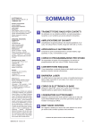
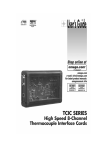
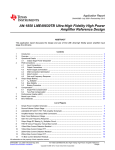
9303 / 9505 Installation & Operation ® ® a v o n s n a tr MAD IN T E HE USA PROFESSIONAL POWER AMPL AMPLIFIER NOTICE - IMPORTANT SAFETY INFORMATION CAUTION RISK OF ELECTRIC SHOCK DO NOT OPEN The lightning flash with arrowhead symbol within an equilateral triangle is intended to alert the user to the presence of uninsulated "dangerous voltage" within the product's enclosure, that may be of sufficient magnitude to constitute a risk of electric shock to persons. ! WARNING: TO PREVENT FIRE OR SHOCK HAZARD, DO NOT EXPOSE THIS EQUIPMENT TO RAIN OR MOISTURE. ! The exclamation point within an equilateral triangle is intended to alert the user of the presence of important operating and maintenance (servicing) instructions in the literature accompanying the appliance. 1. READ INSTRUCTIONS All the safety and operating instructions of your Hafler equipment should be read before power is applied to the equipment. 2. RETAIN OWNER'S MANUAL These safety and operating instructions should be retained for future reference. ment. Furthermore, extension cords or power strips must provide the same three wire grounded connection. It is important that the blades of the equipment’s plug be able to fully insert into the mating receptacle. Never remove the round grounding pin on the plug in an attempt to mate to a two wire ungrounded receptacle: use a grounding adaptor with the grounding tab or wire suitably connected to earth ground. 3. HEED WARNINGS All warnings on the equipment and in the operating instructions are important and should be followed. 11. NON-USE PERIODS During periods of extended non-use, the power cord should be unplugged from the power source. 4. FOLLOW INSTRUCTIONS All operating and use instructions are important and should be followed. 12. CLEANING The equipment should be cleaned only as detailed in the operating instructions. 5. HEAT The equipment should be kept away from areas of high temperature, i.e., heater vents, radiators, stoves/ovens, fireplaces, etc. 6. VENTILATION The equipment should be used in an area suitable for proper ventilation. Care should be taken not to impede airflow in and around the cabinet. Do not mount on a carpeted shelf or in a sealed enclosure. Allow for proper clearance above the equipment. 13. OBJECT AND LIQUID ENTRY Care should be taken so that objects and/or liquids, such as cleaning fluids or beverages, are not spilled into the enclosure of the equipment. 7. 8. 9. 14. DAMAGE REQUIRING SERVICE Hafler equipment should be serviced by qualified service personnel when: A. The power supply cord or plug has been damaged, or WATER AND MOISTURE The equipment should not be used in or around water, such as a bathtub, sink, or swimming area. Also, the equipment should not be used in areas prone to flooding, such as a basement. B. Objects have fallen, or liquid has been spilled into the equipment, or C. The equipment has been exposed to rain, or POWER SOURCES The equipment should be connected only to a power source of the same voltage and frequency as that listed on the rear panel above the power cord entry point. D. The equipment does not appear to operate normally or exhibits a marked change in performance, or E. The equipment has been dropped, or the enclosure has been damaged. POWER CORD PROTECTION Power cords should be arranged so they do not interfere with the movement of objects in the room: people, fan blades, utility carts, etc. Also, care should be taken that the cord is not pinched or cut, and placed so it is not in danger of being pinched or cut, as in under a rug, around a tight corner, etc. 15. SERVICING The user should not attempt to service the equipment beyond that which is described in the operating instructions. All other service should be referred to qualified service personnel. 16. CARTS AND STANDS The equipment should be used with carts or stands only of sufficient strength and stability for the use intended. 10. POWER CORD GROUNDING The power supply cord is of a three wire grounded type, designed to reduce the risk of electric shock sustained from a live cabinet. It is assumed to be of suitable length for most uses of the equipment. The use of extension cords and power strips is discouraged unless they are of suitable rating to deliver the required total current for safe operation of all connected equip- An equipment and cart combination should be moved with care. Quick stops and starts, excessive force, and uneven surfaces may cause the equipment and cart combination to topple. –i– PERFORMANCE SPECIFICATIONS 9303/9505 Full Power Bandwidth: 0.15Hz to 300kHz Signal-to-Noise: >100dB “A” Weighted Slew Rate: 150 V/µs CMRR: 75dB at 1kHz Gain: +29dB max. 9303 Power Rating: 150 wpc @8 Ω, 225 wpc @ 4Ω, 450 Watts mono @ 8Ω Distortion: 0.07% THD 20-20Hz, Typically 0.005% THD 1kHz, at rated power into 8Ω Damping Factor: 800 (to 1kHz); 80 (to 20kHz); 20 (to 100kHz) into 8Ω Input Sensitivity Range: 1.22 Vrms for 150W into 8Ω, 1.06Vrms for 225W into 4Ω Dimensions: 19"W x 12-1/2"D x 3-1/2"H (excluding feet) Weight: 36 lbs. (16.4kg) Power Consumption: Quiescent, 84 VA; at rated power, 612 VA (150W into 8Ω, both channels driven) 9505 Power Rating: 250 wpc @8 Ω, 375 wpc @ 4Ω, 750 Watts mono @ 8Ω Distortion: 0.1% THD 20-20Hz, Typically 0.005% THD 1kHz, at rated power into 8Ω Damping Factor: 1000 (to 1kHz); 100 (to 20kHz); 20 (to 100kHz) into 8Ω Input Sensitivity Range: 1.58 Vrms for 250W into 8Ω, 1.37Vrms for 375W into 4Ω Dimensions: 19"W x 12-1/2"D x 5-1/4"H (excluding feet) Weight: 50 lbs. (22.7kg) Power Consumption: Quiescent, 132 VA; at rated power, 1020 VA (250W into 8Ω, both channels driven) – ii – TABLE OF CONTENTS SAFETY PRECAUTIONS ........................................................................................................................................... i PERFORMANCE SPECIFICATIONS ......................................................................................................................... ii INTRODUCTION ................................................................................................................................................... 1 INSTALLATION Location ........................................................................................................................................................... AC Line ............................................................................................................................................................ Input ................................................................................................................................................................. Balanced Input: 1/4" Tip Ring Sleeve .......................................................................................................... Balanced Input: XLR ................................................................................................................................... Unbalanced Input ...................................................................................................................................... Unbalanced Source with Balanced Input ................................................................................................... Output Connections ......................................................................................................................................... Monophonic Use .............................................................................................................................................. 1 1 2 2 2 2 2 2 2 OPERATION Power Switch ................................................................................................................................................... Balanced/Unbalanced Input Switch .................................................................................................................. Ground Switch ................................................................................................................................................. Mono Switch .................................................................................................................................................... Load Fault Protection ........................................................................................................................................ Warm Up ......................................................................................................................................................... Cleaning and Maintenance ............................................................................................................................... Schematic Diagram .......................................................................................................................................... PC Board Layout ............................................................................................................................................... Parts List ........................................................................................................................................................... 9303/9505 Functional Block Diagram .............................................................................................................. 3 3 3 3 3 3 3 4 6 7 8 TECHNICAL INFORMATION Theory and Operation of trans•nova ................................................................................................................ 9 Circuit Implementation ..................................................................................................................................... 9 Calibration ..................................................................................................................................................... 10 Common Mode Rejection ........................................................................................................................ 10 Bias .......................................................................................................................................................... 10 WARRANTY ......................................................................................................................................................... 11 INTRODUCTION The Hafler 9303 and 9505 are two channel professional power amplifiers. Passive cooling with large heatsinks is used for low mechanical noise. Our patented trans•nova circuit topology and MOSFET output stage ensures trouble free, long term operation and is backed by our seven year warranty. This manual contains information on using the 9303 and 9505 amplifiers. It is organized into three main sections. “Installation” covers the location and connection of the amplifier in the system. Like many precision components careful attention to the initial setup can yield dividends in higher performance and trouble-free use. “Operation” covers the controls and features of the amplifiers and how to use them to get the best effect. The “Technical Information” section contains information on the circuit implementation and the schematic diagram and parts list. We strongly urge reading over the Installation and Operation portions of this manual before putting the amplifier into service. The circuitry used in the 9303 and 9505 is the latest refinement of our trans•nova (TRANSconductance NOdal Voltage Amplifier, US Patent 4,467,288) circuit. The 9303 and 9505 utilize our proprietary DIABLO (patent application in progress) transconductance driver stage which combines the linearity of Class A operation with the current headroom of a Class B system. When used in combination with the robust output stage used with these models, DIABLO yields lower high frequency distortion without the sonic penalties associated with increasing the negative feedback. The 9303 and 9505 have fully differential inputs for use in balanced line systems. The balanced input terminals work with either 1/4" TRS phone or XLR plugs. Gold-plated RCA phono jacks are available for use with unbalanced source components. The output terminals are gold-plated binding posts, spaced on 3/4" centers for use with dual banana plugs. For high power applications, the amplifier can run in bridged mono for double the output voltage. Using state-of-the-art surface mount assembly equipment in our manufacturing facility ensures consistency and reliability. INSTALLATION LOCATION The 9303 and 9505 can produce considerable heat in normal operation so the primary consideration when determining a location for the amplifiers is to allow for adequate ventilation. The large heatsinks provide unrestricted airflow, but care must be taken to keep the slots in the bottom panel and top cover clear, as well. If the amplifier is mounted in an equipment rack, make sure adjacent equipment does not impede cool air flow through the amplifier bottom and out the top. The attached feet provide sufficient clearance for the bottom when the amplifier is resting on a hard surface. Inadequate ventilation can shorten component life, especially when other equipment raises the ambient air temperature, so a circulating fan should be considered in tight quarters. The power transformer can generate a substantial magnetic field, so caution should be exercised in the placement of low level components such as a tape deck, mixer or mic preamp to avoid inducing noise in the low level circuitry. AC LINE The 9303 and 9505 operate from a 120 volt, 60Hz AC power line. Connection is made by an IEC Type 320, grounded line cord. For safety considerations only a properly grounded (earthed) receptacle should be used. If a grounded circuit is not available do not break off the ground pin; use the proper adapter plug for a two wire receptacle. Located inside the amplifier is the line fuse which interrupts the power to the amplifier. If this fuse blows replace it only with the same type and rating fuse. The correct replacement fuse value is included in the parts list in the “Technical Information” section of this manual. If the replacement fuse blows, this is an indication of a fault with the amplifier. Servicing should be performed only by a qualified technician. –1– INPUT The 9303 and 9505 have input jacks for both balanced and unbalanced input signals. The unbalanced inputs use conventional RCA phono jacks. When using the RCA inputs, the rear panel BALANCED/UNBALANCED switch must be set to the UNBALANCED position. The balanced input jacks are dual function connectors which accept 1/4" TRS (Rip Ring Sleeve) phone or XLR plugs. Set the BALANCED/UNBALANCED switch to the BALANCED Position to use these jacks. The connector pin-out is printed on the rear panel of the amp. Balanced Input: 1/4" Tip Ring Sleeve The 1/4" balanced input jack is connected according to conventional usage with the Tip high (+), Ring return (–) and the Sleeve ground shield. Balanced Input: XLR The XLR balanced input jack is connected according to the IEC International Standard, with pin 2 high (+), pin 3 return (–) and pin 1 ground shield. When preparing to use the amplifier, check the output configuration of the source unit to maintain the proper signal polarity. Unbalanced Input Many popular mixers use unbalanced RCA phono jacks for the monitor outputs. For short cable runs RCA audio patch cable can be used without any system performance penalty. Check the mixer specs for the maximum cable length it will drive. Make sure the BALANCED/UNBALANCED switch is set for UNBALANCED operation. Unbalanced Source with Balanced Input Better noise rejection for long cable runs can be achieved by using a twisted pair balanced cable from the unbalanced source. At the source end of the cable, connect an RCA plug with the return (–) wire and shield connected to the ground shell of the plug. Wire the plug at the amplifier end of the cable the same as for the regular balanced input connection. OUTPUT CONNECTIONS The speaker output connectors are dual binding posts. These binding posts will directly accept 12 AWG wire or banana plugs and are spaced on 3/4" centers to accept dual banana plugs. MONOPHONIC USE For systems with high power requirements, the amplifiers can be configured for single channel bridged mono operation. To bridge the amplifier, set the rear panel STEREO/MONO switch to the Mono position; use only the left channel input, and connect the speaker to the red output binding posts. When the amplifier is bridged, the output is floating. Any speaker which requires a common ground from the amplifier output cannot be used in this application. Since a bridged amplifier shares the load between the two channels, the amplifier will effectively drive half of the load. Therefore, for bridged mono operation we recommend using an eight ohm load as the minimum impedance. –2– OPERATION POWER SWITCH The POWER switch is located on the front panel of the amplifier. An internal lamp indicates when it is turned on. Standard practice is to turn the amplifier on last and off first when switching components individually to prevent sending damaging transients, generated in the source components, to the speakers. It is possible to leave the power switch in the on position and switch the amplifier remotely through a power distribution block or preamp switched outlet. When doing so make sure the switch is rated for the current required by the amplifier. BALANCED/UNBALANCED INPUT SWITCH The BALANCED/UNBALANCED switch configures the input grounding when using the RCA phono input jacks. In the UNBALANCED position the balanced differential input return (–) port is grounded inside the amplifier. This prevents noise pickup or unstable amplifier operation caused by the open input. In the BALANCED position the differential amplifier inputs are connected to the hot (+) and (–) incoming signal connectors. GROUND SWITCH Ground loops are characterized by a hum or buzz in the system and are caused by a voltage potential difference between two points in a ground circuit. Ground loops are aggravated when multiple paths exist for a given circuit. Mounting components in a rack with metal rails may introduce ground loops between associated equipment, because the rails can establish an additional ground path. The CHASSIS/FLOAT switch allows you to select the amplifier grounding scheme for best system compatibility. With the switch in the CHASSIS position all signal grounds are referred to the chassis and power line ground. In the FLOAT position the signal ground is decoupled from the chassis. The position of the switch is determined by the overall noise in the system; choose the position which gives the lowest hum. MONO SWITCH Conventional two-channel stereo operation is obtained with the STEREO/MONO switch in the STEREO position. For high powered single channel use, set the switch to MONO and use the left channel input and the RED binding posts only for the output. For thermal considerations we do not recommend using less than an eight ohm load on the amplifier when running it in mono. When the switch is set in the mono position the left channel (+) and (–) inputs are connected to the right channel in reversed polarity, which inverts the right channel output. LOAD FAULT PROTECTION Because of the self-protecting properties and fault tolerance of the lateral MOSFETs used in the 9303 and 9505, elaborate voltage and current limiting protection schemes are not necessary. To prevent damage to the amplifier from a fault in the loudspeaker load, the power supply B+ and B– rails are fused. Check these fuses if the sound is garbled or there is no output. The fuses should not blow under normal use and a blown fuse is usually an indication of a fault. The fault could be a bad connection, a problem with the speaker or a short in the speaker line. Disconnect power to the amplifier before removing the cover. WARM UP In order to achieve the best sonic performance from the amplifier, we recommend letting it warm up for 1 hour before beginning any critical listening. The amplifier will not deliver its full potential sound quality before this time has passed. CLEANING AND MAINTENANCE There is no requirement for regular maintenance on the electronic components of the amplifier. If the case becomes soiled it can be cleaned using a soft cloth and a mild detergent, such as spray window or glass cleaner. If the amplifier is located in a particularly dusty environment cleaning the inside with compressed air or vacuuming every 18 to 24 months is sufficient. –3– SCHEMATIC DIAGRAM NOTES: Unless specified otherwise 1. All resistors in ohms 2. All capacitors in microfarads 3. Component Designators: 1-99: Left Channel 101-199: Right Channel 201-299: Common Parts 301-399: Chassis/Power Supply 4. Left Channel Only Shown 5. Stereo/Mono Switch Shown in Stereo 6. Balanced/Unbalanced Switch Shown in Balanced Position 7. Chassis/Float Ground Switch Shown in Float Position –4– –5– PC BOARD LAYOUT –6– PARTS LIST DESIGNATOR VALUE ALL RESISTORS IN OHMS PART # R1, R101 R2, R102 R3, R103 R4, R104 R5, R105 R6, R106 R7, R107 R8, R108 R9, R109 R10, R110 R11, R111 R12, R112 R13, R113 R14, R114 R15, R115 R16, R116 R17, R117 R18, R118 R19, R119 R20, R120 R21, R121 R22, R122 R23, R123 R24, R124 R25, R125 R26, R126 R27, R127 R28, R128 R29, R129 R30, R130 R31, R131 R32, R132 R33, R133 R34, R134 R35, R135 R36, R136 R37, R137 R38, R138 R39, R139 R40, R140 R41, R141 R42, R142 R43, R143 R44, R144 R45, R145 R46, R146 R47, R147 R48, R148 R49, R149 R50, R150 R51, R151 R52, 152 R53, R153 R54, R154 R55, R155 R56, R156 R57, R157 R58, R158 R202 R203 R205 R206 R207 R208 R209 R210 R211 R212 RM/4-4752C RM/4-4752C RM/4-102C RM/4-102C RM/4-225C RM/4-101C RM/4-223C RM/4-101C RM/4-101C RM/4-3320C RM/4-101C RM/4-3320C RM/4-0221C RM/4-0221C RM/4-0221C RM/4-0221C RM/4-102C RM/4-2802-03 RM/4-9090C RM/4-101C RM/4-3320C RM/4-4750C RM/4-3320C RM/4-560C RM/4-560C RM/4-3321C RM/4-202C RM/4-103C RM/4-101C RM/4-102C RM/4-101C RM/4-101C RM/4-202C RM/4-102C RM/4-102C RM/4-102C RM/4-101C RM/4-102C RM/4-101C RM/2802-03 RM/4-101C RM/4-101C RM/4-102C RM/4-0475C RM/4-102C RM/4-101C RM/4-101C RM/4-0475C RM/4-4750C RM/4-4750C RM/4-4750C RM/4-4750C RMP/4-5622-03 RM/4-221C RM/4-221C RM/4-221C RM/4-221C RM/4-000C RM/4-3921C RM/4-3921C RM/4-223C RM/4-223C RM/4-223C RM/4-223C RM/4-6043C RM/4-474C RM/4-102C RM/4-102C 47.5k, 1/4W, 1% 47.5k, 1/4W, 1% 1k, 1/4W, 5% 1k, 1/4W, 5% 2.2M, 1/4W, 5% 100, 1/4W, 5% 22k, 1/4W, 5% 100, 1/4W, 5% 100, 1/4W, 5% 332, 1/4W, 1% 100, 1/4W, 5% 332, 1/4W, 1% 22.1, 1/4W, 1% 22.1, 1/4W, 1% 22.1, 1/4W, 1% 22.1, 1/4W, 1% 1k, 1/4W, 5% 28k, 1/4W, 1% 909, 1/4W, 1% 100, 1/4W, 5% 332, 1/4W, 1% 475, 1/4W, 1% 332, 1/4W, 1% 56, 1/4W, 5% 56, 1/4W, 5% 3.32k, 1/4W, 1% 2k, 1/4W, 5% 10k, 1/4W, 5% 100, 1/4W, 5% 1k, 1/4W, 5% 100, 1/4W, 5% 100, 1/4W, 5% 2k, 1/4W, 5% 1k, 1/4W, 5% 1k, 1/4W, 5% 1k, 1/4W, 5% 100, 1/4W, 5% 1k, 1/4W, 5% 100, 1/4W, 5% 28k, 1/4W, 5% 100, 1/4W, 5% 100, 1/4W, 5% 1k, 1/4W, 5% 47.5, 1/4W, 1% 1k, 1/4W, 5% 100, 1/4W, 5% 100, 1/4W, 5% 47.5, 1/4W, 1% 475, 1/4W, 1% 475, 1/4W, 1% 475, 1/4W, 1% 475, 1/4W, 1% 56.2k, 1/4W, 1% 220, 1/4W, 5% 220, 1/4W, 5% 220, 1/4W, 5% 220, 1/4W, 5% 0, 1/4W, 1% 3.92k, 1/4W, 1% 3.92k, 1/4W, 1% 22k, 1/4W, 1% 22k, 1/4W, 1% 22k, 1/4W, 1% 22k, 1/4W, 1% 604k, 1/4W, 1% 470k, 1/4W, 4% 1k, 1/4W, 5% 1k, 1/4W, 5% –7– DESIGNATOR VALUE PART # R213 R214 R215 220, 1/4W, 5% 220, 1/4W, 5% 10k, 1/4W, 5% RM/4-221C RM/4-221C RM/4-103C P1, P101 P2, P202 200, Trim Pot 200 Trim Pot RVH-201 RVH-201 D1, D101 D2, D102 D3, D103 D4, D104 D5, D105 D6, D106 D7, D107 D201 D202 D203 D204 BAV99L BAV99L BAV99L BAV99L BAV99L BAV99L BAV99L 1N5245B 15V BAV99L 1N5245B 15V 1N5245B 15V SS-260SM SS-260SM SS-260SM SS-260SM SS-260SM SS-260SM SS-260SM SS-212 SS-260SM SS-212 SS-212 U1, U101 U9, U109 U201 U202 U203 NPDS5566 NPDS5566 TL072CD LM337 LM317 SS-0865 SS-0865 SS-143SM SS-240-056 SS-240-056 C1, C101 C2, C102 C3, C103 C4, C104 C5, C105 C6, C106 C7, C107 C8, C108 C9, C109 C10, C110 C11, C111 C12, C112 C13, C113 C14, C114 C15, C115 C16, C116 C17, C117 C18, C118 C19, C119 C20, C120 C21 C201, 202 C203 C204 C205 C206 C207 C208 C209 C210 C211 C215 330pF, 500V 330pF, 500V 0.47µF, 50V 0.1µF, 50V 100µF, 50V 0.1µF, 50V 100µF, 50V 0.1µF, 50V 0.1µF, 50V 7pF, 500V 100pF, 500V 100pF, 500V 0.047µF, 50V 22pF, 500V 680pF, 500V 47pF, 500V 4.7µF, 160V 4.7µF, 160V 20,000µF, 100V 20,000µF, 100V 0.01µF, 1000V 0.1µF, 50V 1000µF, 50V 1000µF, 50V 0.1µF, 50V 0.1µF, 50V 100µF, 50V 100µF, 50V 10µF, 50V 4.7µF, 160V 4.7µF, 160V 0.01µF, 1600V CM-331-024 CM-331-024 CYV-474 CYV-104-024 CER-107C-024 CYV-104-024 CER-107C-024 CYV-104-024 CYV-104-024 CM-070-024 CM-101-024 CM-101-024 CYV-473-024 CM-220-024 CM-681-024 CM-470-024 CPP-475MC CPP-475MC CER-209E CER-209E CD-103/20-024 CDS-104CCDB CER-108C-024 CER-108C-024 CYV-104-024 CYV-104-024 CER-107C-024 CER-107C-024 CER-106C-024 CTR-475A-024 CTR-475A-024 CD-103A-024 SW1 SW2 SW3 DPDT Switch DPDT Switch DPDT Switch SW-0280 SW-0280 SW-0280 S201 Power Switch SWH-152B TS-201 Inrush Limiter SSH-618 Q2, Q102 Q3, Q103 Q4, Q104 Q5, Q105 Q6, Q106 Q7, Q107 MMBT5088L MMBT5088L MMBT5088L MMBT5087L MMBT5088L MMBT5087L SS-0114 SS-0114 SS-0114 SS-0115 SS-0114 SS-0115 DESIGNATOR Q8, Q108 Q10, Q110 Q11, Q111 Q12, Q112 Q13, Q113 Q14, Q114 Q15, Q115 Q16, Q116 Q17, Q117 Q45, Q145 Q46 Q146 Q47, Q147 Q48, Q148 Q49, Q149 Q50, Q150 Q51, Q151 Q52, Q152 Q201 Q202 Q203 VALUE MMBT5087L MMBT5088L MMBT5087L MMBT5088L MMBT5087L MPS-A56 MPS-A56 MPS-A06 MPS-A06 2SK1058 2SK1058 2SK1058 2SK1058 2SJ162 2SJ162 2SJ162 2SJ162 MMBT5087L MMBT5088L MMBT5088L PART # SS-0115 SS-0114 SS-0115 SS-0114 SS-0115 SS-101A SS-101A SS-102A SS-102A SSH-741T SSH-741T SSH-741T SSH-741T SSH-740T SSH-740T SSH-740T SSH-740T SS-0115 SS-0114 SS-0114 F1, F101 F2, F102 F201 F203, F204 AGC 10A Fuse AGC 10A Fuse 15A Slo/Blo 2.5A Fast Mini FS-010 FS-010 FS-015SB FS-0390 DESIGNATOR BR201 BR301 BR-302 VALUE Bridge Rectifier Bridge Rectifier Bridge Rectifier PART # SS-222 SSH-609 SSH-609 IEC Connector IEC Line Cord Dual Binding Post MOSFET Insulator CC-0918 FA-0209 CC-0867 HWH-442 IEC Line Cord FAH-146 C19, C119 C20, C120 15000µf, 75V 15000µf, 75V CER-159ES CER-159ES F201 10A, Slo/Blo FS-010SM Q47, Q147 Q50, Q150 Not Used 2SK/1058 2SJ/162 9303 Differences 9303 / 9505 F UNCTIONAL B LOCK D IAGRAM SERVO INTEGRATOR (+) (+) BUFFER (+) LEFT INPUT (–) (–) BUFFER (–) LEFT CH. AMPLIFIER LEFT OUTPUT BALANCED/ UNBALANCED SWITCH SERVO INTEGRATOR (+) (+) BUFFER (+) RIGHT INPUT (–) (–) BUFFER (–) RIGHT CH. AMPLIFIER RIGHT OUTPUT STEREO/MONO SWITCH RIGHT CH. HIGH VOLTAGE POWER SUPPLY LEFT CH. HIGH VOLTAGE POWER SUPPLY –8– LOW VOLTAGE POWER SUPPLY SOFT TURN ON/OFF SYSTEM TECHNICAL REFERENCE THEORY AND OPERATION OF trans•nova The (TRANSconductance NOdal Voltage Amplifier) principle is based on our 1984 U.S. Patent 4,467,288. This patent describes the advantages of audio power amplifiers in which a MOSFET output stage is connected in a grounded source configuration. In this connection the output stage has its full voltage gain of typically 20dB (ten times), instead of the usual 1dB loss of voltage follower designs. It is an inevitable result of electrical physics that this output with gain inherently increases the power gain (for the same bandwidth) of the output stage by typically ten times over the conventional follower connection, using exactly the same MOSFET devices. The output stage is thus now ten times less wasteful of its incoming drive power. The driver stage can now be of a low voltage (±24 volts) nature and be designed along the same principles always used in high quality preamplifiers: Class A operation, high linearity, and wide bandwidth. A topology utilizing an output stage with gain yields a much simpler, shorter total signal path than that of the usual high voltage driver designs. The number of serial stages is reduced from five or more, to only three. But all of the above does not make an amplifier trans•nova. The output stage is further refined into a trans-impedance stage (current-to-voltage converter), to achieve extremely short loop (fast) negative feedback. The output stage is driven cooperatively by a transconductance stage (voltage-to-current converter). The 9303and 9505are the most sophisticated amplifiers we have yet developed utilizing the basic trans•nova principle. And, although the measured specifications are very good, the numbers do not describe the realistic sound of the amplifiers. CIRCUIT IMPLEMENTATION Earlier models of amplifiers we have offered using the trans•nova topology have earned the reputation for clean, natural sounding reproduction. A conservative, purist design approach was used to avoid compromising the desirable characteristics of the trans•nova circuits. Circuit innovation was not prevented by this conservatism; as is evident in the discoveries which resulted in development of the DIABLO circuitry to be discussed shortly, and the novel balanced input system. Many “balanced” amplifiers are merely conventional unbalanced designs with a Balanced-to-Unbalanced converter (usually IC op-amp based) preceding the power amplifier. The 9303 and 9505, however, are true differential input power amplifiers. Each (+) and (–) input port has been buffered to allow direct signal access to the differential amplifier, without conversion to unbalanced form. Deactivating the Balanced Mode is accomplished via a rear panel switch that grounds the (–) inputs, effectively converting the amplifier to unbalanced operation. The input stage is a JFET differential amplifier. This circuit configuration results in excellent front end headroom and extremely low intermodulation effects. The ultra low noise characteristic of the JFETs virtually eliminates noise “mixing” (intermodulation) with the music signal, reducing discordant product frequencies known as “noise grain” or “noise fuzz.” A servo integrator has been employed to establish minimal DC offset. This circuit monitors the DC offset at the output of the amplifier, and injects an equal but opposite DC voltage into the (+) port of the differential input, thereby cancelling the offset. This method eliminates the need for a sonically degrading electrolytic capacitor in the audio path, and provides superior subsonic frequency response. –9– The final output stage utilizes lateral MOSFETs; four pairs are used for each channel in the 9505 and three pairs in the 9303. These devices, unlike conventional bipolar transistors do not exhibit “thermal runaway.” Thermal runaway is a phenomenon whereby a transistor heats up as it draws more current, which causes it to get hotter, and conduct more current, and so on until the device self destructs. Since the MOSFETs are inherently self protecting, no sonically degrading, complex circuitry is required to monitor and protect the devices. The lateral MOSFETs also have a linear input to output transfer function. Their connection in circuits and their operating characteristics are very similar to vacuum tubes, which is perhaps responsible for their widely recognized sonic trait of being “musical” and non-fatiguing. Operation of the transconductance stage is a major factor in the reproduction quality of the amplifier. The number of MOSFETs used at the output stage of the 9303 and 9505 imposes sufficient capacitive load on the transconductance stage that if a conventional Class A stage were used (having intrinsically a 2:1 limit on peak-to-quiescent current) it would begin to show “stress” at the higher audio frequencies. The newly perfected DIABLO driver system (Dynamically Invariant A-B Linear Operation; patent application in progress) satisfies the current headroom requirement by smoothly and continuously varying the current transfer ratios of the two transconductance paths, under the control of the signal current itself. This implementation allows the current transfer ratio of one path to be smoothly and continuously reduced to zero while the other is smoothly and continuously increased by a factor of two. What is remarkably new here is that when this normally-limiting 2:1 value is reached there is now about 14dB of additional, perfectly linear current headroom left to drive the MOSFETs! The result is a dramatic decrease in high-frequency distortion combined with higher ultrasonic stability – the “Holy Grail” of amplifier design. The power supply utilizes a UI style transformer with a separate primary for each channel. The transformer has a separate secondary for each channel high voltage power supply, each feeding a conventional split full wave bridge rectifier. High voltage power supply capacitance is 20,000µF per rail for each channel for the 9505 and 5,000 for the 9303. The third transformer secondary feeds a regulated supply for the input stage and driver circuitry. Low voltage power supply capacitance is 1,000µF per rail, with additional decoupling for each channel. CALIBRATION Common Mode Rejection: The input common mode null is adjusted by the trim pot R1 (R101 for the left channel). The CMRR should be greater than 75dB below rated output. If the CMRR requires adjustment, feed the amplifier input with a common mode signal and adjust R1. Disconnect the power to the amplifier before removing the cover. Use a sinewave generator set to 1 volt output at 1kHz. Connect the generator signal output to the tip and ring of a 1/4" plug and ground to the sleeve. Plug this into the amplifier input. Connect an AC voltmeter to the amplifier output binding posts. Adjust R1 to give the lowest voltage output from the amplifier. For a temporary adjustment when a signal generator and voltmeter are not available, use an FM tuner and tune it to an unused station as your signal source, and connect the output to the amplifier as described above. Connect the amplifier output to a small full range speaker and adjust R1 for the lowest output from the speaker. Bias: The bias control establishes the quiescent Class AB output current of the amplifier. The bias should not need readjustment from the factory setting; however, if the amplifier is repaired and output devices have been changed, or if the two channels of the amplifier do not run at the same temperature, calibrating the bias is necessary. Disconnect the power to the amplifier before removing the cover. To adjust the bias, disconnect the input and speakers and remove the B+ fuse for that channel. Connect an amp meter across the now vacant fuse clips and adjust R45 (R145 for the left channel) to get a current reading of 300mA for the 9303, 400mA for the 9505. – 10 – SERVICE POLICY AND LIMITED WARRANTY If you encounter any difficulty or have any question concerning your 9303 and 9505 Amplifier, please call our Technical Support Department weekdays, 8:00 a.m. to 3:30 p.m., Mountain Standard Time, at 800-795-2385. Should you have any doubts as to whether the amplifier is malfunctioning and requires service, please call us before sending it in for repair. All units being returned (regardless of warranty status) must receive a Return Authorization (RA) number. In addition, we can offer troubleshooting assistance that may simplify or even eliminate the need for factory service. The Hafler 9303 and 9505 Amplifiers are warranted to the original owner (non-transferrable) for seven years from the date of purchase, including parts, labor, and return shipping costs within the Continental United States, Alaska, and Hawaii. This warranty applies only to products sold in the United States Of America. For warranties outside the U.S.A., please contact your local agent. It is the owner’s responsibility to pay shipping (preferably United Parcel Service, UPS) to the factory: collect shipments will not be accepted. Units under warranty should be accompanied by a copy of the dated Bill Of Sale. Use the original carton and all packing material, with the RA number clearly marked on the outside of the package. Be sure to include a return address, the RA number, a daytime telephone number, and a brief description of the difficulty, including whether it occurs continuously or intermittently. This warranty gives you specific legal rights. You may also have other rights which may vary from state to state. – 11 – HAFLER PROFESSIONAL A DIVISION OF ROCKFORD CORPROATION 546 SOUTH ROCKFORD DRIVE TEMPE, ARIZONA 85281 U.S.A. IN U.S.A. (602) 967-3565 IN EUROPE, FAX (49) 4207-801250 IN JAPAN, FAX (81) 559-79-01265 MAN-0587-D 4/95