1
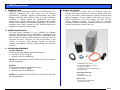
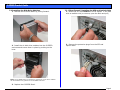
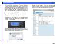
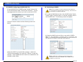
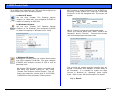
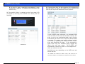
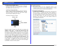
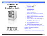
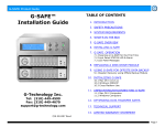
G-SPEED Product Guide
G-SPEED™
Product Guide
TABLE OF CONTENTS
1. INTRODUCTION
2. SAFETY PRECAUTIONS
3. SYSTEM REQUIREMENTS
4. WHAT’S IN THE BOX
5. G-SPEED OVERVIEW
6. LED Indicators
7. INSTALLING G-SPEED
7.1 Installing ATTO HBA
7.2 Installing Disk Drive modules
7.3 Installing SFP and Optical Cable (FC version)
7.4 Installing SCSI Terminator and Cables (SCSI version)
7.5 Setting SCSI ID
7.6 Formatting G-SPEED
8. MANUAL CONFIGURATION
8.1
8.2
8.3
8.4
Connecting to the GUI
Setting SCSI ID via the GUI (SCSI version)
Initializing G-SPEED / Creating a RAID Set
Deleting a RAID Set
9. HARDWARE MONITORING
9.1 Silencing the Audible Alarm
10. SYSTEM CONTROL
G-Technology Inc.
Tel: (310) 449-4599
Fax: (310) 449-4670
[email protected]
10.1 Silencing the Audible Alarm
10.1 Alert by Mail Config
10.1 View Events / Mute Beeper
11. TECHNICAL SUPPORT
12. LIMITED WARRANTY
APPENDIX
Description of RAID Levels
P/N GSPEED120506
Page 1
G-SPEED Product Guide
Page 2
G-SPEED Product Guide
Page 3
G-SPEED Product Guide
1. INTRODUCTION
Thank you for purchasing G-SPEED from G-Technology, Inc.
(G-Tech)! Designed from the ground up for creative
professionals, G-SPEED supports uncompressed HD video
editing workflows with multiple levels of RAID protection.
G-SPEED is ideally suited for deployment into high
performance creative environments including audio & video
editing, motion graphics and digital photography. G-SPEED is
available with a Fibre Channel or SCSI interface and with a
standard or redundant power supply.
4. WHAT’S IN THE BOX
Take a moment to ensure that the following items are
included in the box. If anything is missing, please call G-Tech
at (310) 449-4599. Please keep the shipping container and
packing materials. In the unlikely event that you need to
return G-SPEED to us for any reason, you must use the
G-Tech shipping container. If the Product is returned
damaged caused by improper packaging, the warranty will be
void and liability will rest with the user.
2. SAFETY PRECAUTIONS
The disk drives contained in your G-SPEED are delicate
electronic instruments and are susceptible to damage due to
excessive physical shock. Place the unit in a vented area away
from moisture or liquids. Please handle the unit with care. Do
not open the case. Doing so will void the warranty. If the
Product is returned with damage caused by improper
handling, the warranty will be void and liability will rest with
the user.
3. SYSTEM REQUIREMENTS
A. Fibre Channel
Fibre Channel Host Adapter Equipped Computer
• Mac OS X 10.2.4 or higher
• Windows 2000 or Windows XP
NOTE: We recommend the ATTO Celerity 4Gb Fibre Channel
Host Bus Adapters.
B. SCSI
SCSI Host Bus Adapter Equipped Computer
• Mac OS X 10.2.4 or higher
• Windows 2000 or Windows XP
NOTE: We recommend the ATTO Ultra 320 Express PCI SCSI
Host Bus Adapters.
•
•
•
•
•
G-SPEED storage system
6 removable SATA drive modules
RS 232 9-pin Cable
Configuration Utility & Installation CD
AC Power cable
Fibre Channel Version:
• SFP Module
• 3m Fibre Channel Cable
SCSI Version:
• 1M HD-HD U320 SCSI Cable
• HD SCSI Terminator
Page 4
G-SPEED Product Guide
5. G-SPEED OVERVIEW
6. LED Indicators
LCD Panel
Removable
Bezel
G-SPEED is equipped with three LED’s located on the front
panel. The top blue LED indicates the system is powered, the
bottom blue LED will flash when the data is being read from
or written to the array and the middle LED will glow RED
when a hardware fault has been detected.
Power LED
Removable Drive
Modules
Status LED
Activity LED
Fibre Channel
Ports
SCSI
Ports
Ethernet
Port
RS232 Port
Removable
Fans
Power
Switch
AC Input
Power Supply
Fault Alert
Reset Button
Removable/Redundant
Power Supply
7. INSTALLING G-SPEED
G-SPEED comes pre-configured in RAID 3 mode and
formatted for MAC OSX. Connecting G-SPEED to your
computer and configuring your system takes just a few
steps…
If an ATTO Host Bus Adapter was included in your kit:
7.1 Install the ATTO HBA:
1. Install the adapter into an empty PCI-X or PCI-E slot in
your system.
2. Install the appropriate ATTO driver (located on the Product
CD) for your operating system
(For detailed installation instructions consult the ATTO Installation Guide
located on the Product CD)
Standard
Power Supply
Page 5
G-SPEED Product Guide
7.2 Installing the Disk Drive Modules
1. Remove the G-SPEED Bezel by pulling forward.
2. Install the six disk drive modules into the G-SPEED
enclosure and secure them in place by pushing on the
lever.
7.3 (Fibre Channel) Installing the SFP and Optical Cable
1. Install the SFP into PORT 0 of the G-Speed. It will seat
with an audible click (to remove, open the latch and pull)
2. Remove the protective plugs from the SFP and
optical cable.
Note: The G-SPEED writes a signature to each drive so the drive modules
can be installed in any position in the G-SPEED enclosure.
3. Replace the G-SPEED Bezel.
Page 6
G-SPEED Product Guide
3. Insert the optical cable into the SFP, it will seat with an
audible click.
4. Remove the protective plug from PORT 0 of the SFP
installed in the ATTO HBA and insert the free end of the
optical cable. It will seat with an audible click.
7.4 (SCSI) Installing the SCSI Cable and Terminator
1. Attach the 68pin HD SCSI terminator to the lower SCSI
port on the G-SPEED as shown.
Tighten the
thumbscrews to hold the terminator in place.
2. Attach the 68pin HD cable to the upper connector on the
G-SPEED as shown. Tighten the thumbscrews to hold
the cable in place.
3. Attached the other end of the SCSI cable to your
system’s SCSI Host adapter.
7.5 (SCSI) Setting the SCSI ID
1. The G-SPEED is set at the factory with a default SCSI ID
of 0, which is perfect for most applications where there
is only one device connected to your SCSI Adapter. If
you have multiple G-SPEEDs (or other devices)
connected to your system you will need to change the
SCSI ID so all the attached devices have different ID’s.
This setting is modified through the web GUI or the front
panel LCD. See section 8.1 for information on
connecting to the G-SPEED GUI and section 8.2 for
information on changing the SCSI ID via the GUI.
To set the SCSI ID via the front panel LCD, follow the
steps on the next page.
Page 7
G-SPEED Product Guide
2. Enter the system through the LCD panel by pressing the
“ENTER” button once. You will be prompted for your
password. Use the UP / DOWN buttons to change the
characters and ENTER button to move the cursor to the
right.
ESCAPE / BACK
UP
ENTER /FORWARD
DOWN
For example, using the default password, hit the UP
button once and “0” will appear on the LCD screen.
Press ENTER to move the cursor right and repeat this
process until four (0) zeros are visible. Hit ENTER 12
more times to move the cursor completely to the right
and you will be logged in.
7.6 Formatting G-SPEED
Now that G-SPEED is physically connected to your computer,
it must be formatted for use with your operating system.
Attention Mac OS X Users!
G-SPEED is set up at the factory for use with Mac
OS X systems. If you are running Mac OS X,
G-SPEED will mount on the OS X desktop right out
of the box. If it becomes necessary to re-format G-SPEED
for Mac OS X, refer to your system documentation.
Attention Windows Users!
G-SPEED must be formatted using Windows Disk
Manager. Please refer to your system documentation
to format G-SPEED for the NTFS file system.
NOTE: Windows XP currently does not support disk volumes
over 2TB in capacity (2048 GB). If your G-SPEED is larger
than 2TB see section 8.3 for information on configuring
G-SPEED to work around this limitation.
Hit the DOWN button until “Volume Set Functions” is
displayed in the window. Hit ENTER once and “Create
Volume Set” should appear. Hit the DOWN button 2
times and Modify Volume Set Attribute” will appear.
Hit ENTER 3 times and the current RAID level will be
displayed (default is RAID3). Hit the DOWN arrow 3
times and SCSI ID will be displayed. Hit ENTER once
and then hit the UP or DOWN buttons to adjust the SCSI
ID.
Hit ENTER when you are satisfied. Hit the BACK button
and you will be prompted to confirm your action. Hit
ENTER 2 times to accept your changes or ESCAPE to exit
without changing.
Page 8
G-SPEED Product Guide
8. MANUAL CONFIGURATION
This section will describe how to manually configure
G-SPEED using the web GUI. The G-SPEED employs a very
sophisticated controller with many advanced options. Some
of these options can erase data on the G-SPEED, so be
careful and backup your data if the G-SPEED has been in
use. These operations are identical on MAC and Windows
systems.
4. After entering the correct username and password the
G-SPEED GUI will appear.
There are many advanced
features accessible through the GUI that are not covered in
this manual. Consult your Dealer for more information.
8.1 Connecting to the G-SPEED GUI
1. Connect the G-SPEED to your computer or network by
connecting an Ethernet cable from the Ethernet port on the
G-SPEED to your host computer or network.
2. G-SPEED will auto configure to your network or direct
attached computer and display the IP address of the
G-SPEED on the LCD panel.
3. Enter this IP address into a web browser to connect to
the G-SPEED GUI. When the login prompt appears type the
default username “admin” and password “0000”.
Note: See section 10.4 to customize the login username / password
Page 9
G-SPEED Product Guide
8.2 (SCSI) Configuring G-SPEED SCSI ID
To set the SCSI ID of G-SPEED select “Modify Volume Set”
on the left NAV bar under “Volume Set Functions.” On the
next page select the volume you wish to set the SCSI ID.
8.3 Initializing G-SPEED
Note: If the G-SPEED is currently configured with a RAID Set.
You must delete the RAID Set before continuing. See Section 8.4
for instructions on deleting a RAID Set.
1. To create a RAID/Volume set on the G-RAID select “Quick
Create” under “Function Menu” on the left navigation bar of
the G-SPEED GUI. The following screen will appear:
Click the “submit” button and the following screen will
appear:
2. Select the RAID level you’d like to use with G-SPEED.
Note: For video applications in protected mode we recommend using
RAID 3. For maximum performance and capacity we recommend RAID 0.
See Appendix A for details on other RAID levels supported
Select the SCSI ID you would like to assign. Check the
“Confirm the Operation” box and click “Submit” to save the
changes. The G-SPEED and will need to be restarted for the
changes to take effect.
Note: G-SPEED with capacities over 2TB require special
initialization covered next in Item 3. Skip to Item 4 if your
G-SPEED is less than 2TB.
Page 10
G-SPEED Product Guide
3. G-SPEED with capacities over 2TB must be configured to
work properly with your operating system.
a. Mac OS X Users:
Set the item “Greater Two Terabyte Volume
Support” to “64bit LBA”, this configures G-SPEED to
report full capacity in MAC OSX
b. Windows 64 Users:
Set the item “Greater Two Terabyte Volume
Support” to “for Windows”, this configures G-SPEED
to report full capacity in Windows 64 (or Vista)
c2. Continue to create Volumes on the G-SPEED by
selecting “Create Volume Set” under the “VolumeSet
Functions” on the left navigation bar. This screen will
appear:
c3. Hit “submit” to enter the configuration page.
Select your desired RAID level, check “Confirm the
Operation” and hit “Submit”. Continue this process
until all available space has been used.
c. Windows XP Users:
Windows XP currently does not support disk volumes
over 2TB in capacity (2048 GB). You must configure
G-SPEED with multiple volumes of 2TB or less as
described here:
c1. Choose “Quick Create”, select your RAID level
and leave the default setting of “No” under
“Greater Two Terabyte Volume Support”. This will
create the maximum Volume size of 2047.97GB
(2199GB from disk) allowed in 32bit systems.
This process will create multiple Volumes that will
appear in Windows Disk Manager as disks ready to
be formatted. It is possible to create one large
Volume in Windows by “spanning” these logical
disks. Refer to your OS documentation for details.
Skip to Item 5
Page 11
G-SPEED Product Guide
4. Accept all other default settings on the Quick Create
page. To complete the process and create the RAID/Volume
Set, check the “Confirm The Operation” check box and hit
the “Submit” button.
This will begin the initialization
process.
8.4 Deleting a RAID set
1. Select “Delete Raid Set” under the “RaidSet Functions”
on the left navigation bar. The following screen will appear:
Check the “Confirm The Operation” checkbox and hit the
“Submit” button.
WARNING: THIS OPERATION WILL DELETE THE
RAID SET AND ANY DATA ON THE G-SPEED!!
5. The initialization process can take from a few seconds to
over 3 hours depending on the RAID level chosen and the
size of the array.
Drives
(6) 250GB Drives
(6) 500GB Drives
(6) 750GB Drives
RAID 0
<1min
<1min
<1min
RAID 3
1h 18m
2h 49m
3h 19m
6. Once the initialization is complete, reboot your computer
system and the array will appear as a blank disk, ready to
be formatted. Refer to your system documentation for
instructions on formatting G-SPEED for your operating
system.
The G-SPEED is now ready to be re-configured. See Section
8.2 for details on configuring a RAID Set on G-SPEED.
9. HARDWARE MONITORING
1. Should hardware fail in your G-SPEED the system alerts
the user in the following ways:
A. The Status LED will flash:
Status LED
Flashing
B. An audible alarm will sound (audible alarm is enabled
by default – to disable see Section 10.1)
Page 12
G-SPEED Product Guide
C. An email is sent to specified email address if email
notification is enabled. (To enable email notification see
Section 10.2)
3. If a hard drive fails, the drive position will be indicated on
the LCD panel, the LED on the failed drive will flash and the
GUI will also report the failed drive and its position.
2. The specific failure is reported on the front panel LCD
(accessed by removing the G-SPEED front bezel) and the
web GUI.
LCD Panel
G-SPEED GUI
If the G-SPEED was configured in a protected RAID
mode the data on the array will be safe, however, the
array is now in an unprotected state* and a further
drive failure will result in loss of the array and the data
it contains. The system can be fully restored to failsafe mode by replacing the failed disk drive module
drive and rebuilding the array. If you purchased a
spare drive with your G-SPEED simply replace the
failed drive with your spare.
The G-SPEED will
automatically rebuild the RAID in the background –
while you continue to work.
Rebuild times vary depending on the RAID level and
size of the unit.
*If G-SPEED was initialized in RAID 6 mode, data would still be
protected as RAID 6 can withstand two simultaneous drive failures.
Page 13
G-SPEED Product Guide
9.1 Silencing the Audible Alarm
During a Failure event, the audible alarm is silenced
through the web GUI or by the LCD panel. (to disable
the audible alarm see section 10.1)
1. Silencing Through Web GUI
Select “View Events/Mute Beeper” under the “System
Control” section on the left navigation bar. This will
silence the beeper and open the “View Events” page
with information regarding the failure.
2. Silencing Through LCD Panel
ESCAPE / BACK
10. SYSTEM CONTROL
This section outlines the user configurable options in the
“System Control” section of the G-SPEED web GUI. Clicking
on the links will bring up windows described below.
10.1 Disable Audible Alarm
G-SPEED has an audible alarm that sounds in the event of a
disk drive failure. To disable this alarm select “Disabled” in
the System Beeper Setting pull-down menu as shown below.
We recommend that you leave all other settings in this menu
at the preset values. You must click the “Confirm The
Operation” box and then click on the “Submit” button for
your changes to take effect.
UP
ENTER /FORWARD
DOWN
Enter the system through the LCD panel by pressing the
“ENTER” button once.
You will be prompted for your
password. Use the UP / DOWN buttons to change the
characters and ENTER button to move the cursor to the right.
For example, using the default password, hit the UP button
once and “0” will appear on the LCD screen. Press ENTER to
move the cursor right and repeat this process until four (0)
zeros are visible. Hit ENTER 12 more times to move the
cursor completely to the right and you will be logged in. Hit
the DOWN button until “Raid System Functions” is displayed
in the window. Hit ENTER and “Mute the Alert Beeper” will
be displayed. Hit ENTER one more time to mute the beeper.
Hit ESCAPE 2 times to exit the system.
Page 14
G-SPEED Product Guide
10.2 Alert By Mail Config
In the event of a system failure G-SPEED can alert up to four
individuals of the problem via an email message. Enter the
applicable information in to the window shown below, click
the “Confirm The Operation” box and then click on the
“Submit” button.
10.3. View Events/Mute Beeper
G-SPEED keeps a log of events that may be viewed by
clicking this link. If a hardware failure occurs and the audible
alarm is enabled, clicking on this link will mute the alarm.
4. Modify Password
Click on this link to modify the login password for G-SPEED.
You must click the “Confirm The Operation” box and then
click on the “Submit” button for your change to take effect.
Page 15
G-SPEED Product Guide
11. TECHNICAL SUPPORT
If you encounter any difficulties while installing G-SPEED,
please contact G-Tech Technical Support via one of the
following ways:
Telephone: (310) 449-4599
Fax: (310) 449-4670
E-mail: [email protected]
Internet: http://www.g-technology.com/support
When contacting Technical Support, make sure to be in front
of your computer and have the following information readily
available:
•
•
•
•
•
•
Your G-SPEED serial number (on bottom of unit)
Operating system and version
Computer brand and model
Fibre Channel host adapter brand and model
Amount of memory installed
Other devices attached to your computer
Thank you for purchasing G-SPEED. If you have any
comments or questions about this manual or the Product,
please call (310) 449-4599, or send an email to
[email protected].
12. LIMITED WARRANTY
G-Technology Inc. (G-Tech) warrants your Product against any
defect in material and workmanship, under normal use, for
the designated warranty period.
If the Product should
become defective within the warranty period, G-Tech, will at
its discretion, repair or replace the Product.
Repair or
replacement parts or Products will be furnished on an
exchange basis and will be either new or reconditioned. All
replaced parts or Products shall become the Property of GTech. This warranty shall not apply if the Product has been
damaged by accident, misuse, abuse or as a result of
unauthorized service or parts. Warranty service is available to
the purchaser by obtaining a Return Material Authorization
number (RMA) and by delivering the Product during the
warranty period to an authorized G-Tech service facility or to
G-Tech. The purchaser shall bear all shipping, packing and
insurance costs and all other costs, excluding parts and labor,
necessary to effectuate repair, replacement or refund under
this warranty. All returned Product must be shipped to
G-Tech in the original shipping container.
For more information on how to obtain warranty service, an
RMA number or to acquire shipping materials, contact G-Tech
at 1653 Stanford Street, Santa Monica, CA 90404,
(310) 449-4599 or [email protected].
IN THE EVENT A PRODUCT BECOMES DEFECTIVE DURING
THE WARRANTY PERIOD, THE PURCHASER’S EXCLUSIVE
REMEDY SHALL BE REPAIR OR REPLACEMENT AS PROVIDED
ABOVE. INCIDENTAL OR CONSEPROUENTAL DAMAGES,
INCLUDING WITHOUT LIMITATION LOSS OF DATA, ARISING
FROM BREACH OF ANY EXPRESS OR IMPLIED WARRANTY ARE
NOT THE RESPONSIBILITY OF G-TECH AND, TO THE EXTENT
PERMITTED BY LAW, ARE HEREBY EXCLUDED BOTH FOR
PROPERTY
DAMAGE,
AND
TO
THE
EXTENT
NOT
UNCONSCIONABLE, FOR PERSONAL INJURY DAMAGE.
Page 16
G-SPEED Product Guide
APPENDIX A
RAID
Level
0
Description
Disk striping
Advantage
Offers the highest
performance and
useable storage
capacity
Disadvantage
No fault tolerance failure of one drive
in the array results
in complete data
loss
Ideal For…
Content creation
applications
1
Mirroring
High level of fault
tolerance
Not the most
efficient in regards
to capacity as
useable storage
space is cut in half
Applications in
which data
security is
paramount
3
Disk striping
with
dedicated
parity drive
High level of
read/write
performance, faulttolerant, disk
failure has
insignificant impact
on performance
5
Disk striping
with
distributed
parity
High read
performance,
medium write
performance, faulttolerant
Disk failure results
in drop in
performance
File servers,
database
applications
6
Disk striping
with dualdistributed
parity
An extension of
RAID 5 with a
second
independent
distributed parity
scheme. High level
of fault tolerance.
Two drives in the
array can fail
without data loss.
Lower performance
than RAID 3 or
RAID 5
Mission critical
data
Just-abunch-ofdisks
Each drive can be
accessed as an
individual volume.
No fault tolerance
Audio
applications
JBOD
Content creation
applications
requiring highperformance and
data security
Page 17