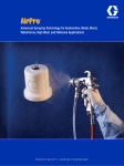
1
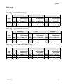
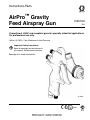
Instructions-Parts
AirPro™ Gravity
Feed Airspray Gun
312579H
ENG
Conventional, HVLP, and compliant guns for specialty industrial applications.
For professional use only.
100 psi (0.7 MPa, 7 bar) Maximum Air Inlet Pressure
Important Safety Instructions
Read all warnings and instructions in
this manual. Save these instructions.
See page 3 for model information.
ti11095A
ll 2 G
Related Manuals
Contents
Related Manuals . . . . . . . . . . . . . . . . . . . . . . . . . . .
Models . . . . . . . . . . . . . . . . . . . . . . . . . . . . . . . . . . .
Gravity Feed without Cup . . . . . . . . . . . . . . . . . .
Gravity Feed with Plastic Cup . . . . . . . . . . . . . . .
2
3
3
3
Gravity Feed with 3M™ PPS™ Cup . . . . . . . . . . .
Warnings . . . . . . . . . . . . . . . . . . . . . . . . . . . . . . . . .
Gun Selection . . . . . . . . . . . . . . . . . . . . . . . . . . . . .
Conventional Guns . . . . . . . . . . . . . . . . . . . . . . .
HVLP Guns . . . . . . . . . . . . . . . . . . . . . . . . . . . . .
Compliant Guns . . . . . . . . . . . . . . . . . . . . . . . . .
Setup . . . . . . . . . . . . . . . . . . . . . . . . . . . . . . . . . . . . .
Ground the Gun . . . . . . . . . . . . . . . . . . . . . . . . .
Flush Before Using Equipment . . . . . . . . . . . . . .
Adjust Spray Pattern . . . . . . . . . . . . . . . . . . . . . .
Operation . . . . . . . . . . . . . . . . . . . . . . . . . . . . . . . . .
Pressure Relief Procedure . . . . . . . . . . . . . . . . .
Apply Fluid . . . . . . . . . . . . . . . . . . . . . . . . . . . . .
Volatile Organic Compounds (VOC) Regulation .
3
4
5
5
5
5
6
6
6
7
8
8
8
8
Daily Gun Maintenance . . . . . . . . . . . . . . . . . . . . . . 9
General Tasks . . . . . . . . . . . . . . . . . . . . . . . . . . . 9
Flush . . . . . . . . . . . . . . . . . . . . . . . . . . . . . . . . . . 9
Clean Gun and Cup . . . . . . . . . . . . . . . . . . . . . . . 9
Clean Nozzle and Air Cap . . . . . . . . . . . . . . . . . 10
Compliant Cleaning Methods . . . . . . . . . . . . . . 10
Troubleshooting . . . . . . . . . . . . . . . . . . . . . . . . . 12
Repair . . . . . . . . . . . . . . . . . . . . . . . . . . . . . . . . . . . 14
Disassembly . . . . . . . . . . . . . . . . . . . . . . . . . . . 14
Fluid Inlet Fitting Replacement . . . . . . . . . . . . . 14
Reassembly . . . . . . . . . . . . . . . . . . . . . . . . . . . . 15
Parts . . . . . . . . . . . . . . . . . . . . . . . . . . . . . . . . . . . . 16
Accessories . . . . . . . . . . . . . . . . . . . . . . . . . . . . . . 18
Repair Kits . . . . . . . . . . . . . . . . . . . . . . . . . . . . . . . 19
Technical Data . . . . . . . . . . . . . . . . . . . . . . . . . . . . 20
Graco Standard Warranty . . . . . . . . . . . . . . . . . . . 22
Graco Information . . . . . . . . . . . . . . . . . . . . . . . . . 22
Related Manuals
2
Manual
Language
313089
Chinese
313091
Dutch
313092
Finnish
313093
French
313094
German
313096
Italian
313097
Japanese
313098
Korean
313100
Portuguese
313101
Russian
313102
Spanish
313103
Swedish
312579H
Models
Models
Gravity Feed without Cup
Conventional
Orifice
Size
in. (mm)
HVLP
Compliant
Max.
Max.
Max.
HVLP/Compliant
HVLP/Compliant
HVLP/Compliant
Air Pressure
Air Pressure
Air Pressure
Model Series psi (MPa, bar) Model Series psi (MPa, bar) Model Series psi (MPa, bar)
0.055 (1.4) 289002
A
N/A
289005
A
29 (0.2, 2.0)
289008
A
35 (0.24, 2.4)
0.070 (1.8) 289003
A
N/A
289006
A
29 (0.2, 2.0)
289009
A
35 (0.24, 2.4)
Gravity Feed with Plastic Cup
Conventional
Orifice
Size
in. (mm)
HVLP
Compliant
Max.
Max.
Max.
HVLP/Compliant
HVLP/Compliant
HVLP/Compliant
Air Pressure
Air Pressure
Air Pressure
Model Series psi (MPa, bar) Model Series psi (MPa, bar) Model Series psi (MPa, bar)
0.055 (1.4) 289011
A
N/A
289014
A
29 (0.2, 2.0)
289017
A
35 (0.24, 2.4)
0.070 (1.8) 289012
A
N/A
289015
A
29 (0.2, 2.0)
289018
A
35 (0.24, 2.4)
Gravity Feed with 3M™ PPS™ Cup
Conventional
Orifice
Size
in. (mm)
HVLP
Compliant
Max.
Max.
Max.
HVLP/Compliant
HVLP/Compliant
HVLP/Compliant
Air Pressure
Air Pressure
Air Pressure
Model Series psi (MPa, bar) Model Series psi (MPa, bar) Model Series psi (MPa, bar)
0.055 (1.4) 289020
A
N/A
289023
A
29 (0.2, 2.0)
289026
A
35 (0.24, 2.4)
0.070 (1.8) 289021
A
N/A
289024
A
29 (0.2, 2.0)
289027
A
35 (0.24, 2.4)
312579H
3
Warnings
Warnings
The following warnings are for the setup, use, grounding, maintenance, and repair of this
equipment. The exclamation point symbol alerts you to a general warning and the hazard
symbols refer to procedure-specific risks. Refer back to these warnings. Additional, productspecific warnings may be found throughout the body of this manual where applicable.
WARNING
FIRE AND EXPLOSION HAZARD
Flammable fumes, such as solvent and paint fumes, in work area can ignite or explode.
To help prevent fire and explosion:
• Use equipment only in well ventilated area.
• Eliminate all ignition sources; such as pilot lights, cigarettes, portable electric
lamps, and plastic drop cloths (potential static arc).
• Keep work area free of debris, including solvent, rags and gasoline.
• Do not plug or unplug power cords or turn lights on or off when flammable fumes
are present.
• Ground all equipment in the work area. See Grounding instructions.
• If there is static sparking or you feel a shock, stop operation immediately. Do not
use equipment until you identify and correct the problem.
• Keep a working fire extinguisher in the work area.
PRESSURIZED EQUIPMENT HAZARD
Fluid from the gun/dispense valve, leaks, or ruptured components can splash in the
eyes or on skin and cause serious injury.
• Follow Pressure Relief Procedure in this manual, when you stop spraying and
before cleaning, checking, or servicing equipment.
• Tighten all fluid connections before operating the equipment.
• Check hoses, tubes, and couplings daily. Replace worn or damaged parts
immediately.
EQUIPMENT MISUSE HAZARD
Misuse can cause death or serious injury.
• Do not exceed the maximum working pressure or temperature rating of the lowest
rated system component. See Technical Data in all equipment manuals.
• Use fluids and solvents that are compatible with equipment wetted parts. See
Technical Data in all equipment manuals. Read fluid and solvent manufacturer’s
warnings.
• Check equipment daily. Repair or replace worn or damaged parts immediately.
• Do not alter or modify equipment.
• Use equipment only for its intended purpose. Call your Graco distributor for
information.
• Route hoses and cables away from traffic areas, sharp edges, moving parts, and
hot surfaces.
• Do not kink or overbend hoses or use hoses to pull equipment.
• Keep children and animals away from work area.
• Comply with all applicable safety regulations.
4
312579H
Gun Selection
WARNING
PERSONAL PROTECTIVE EQUIPMENT
You must wear appropriate protective equipment when operating, servicing, or when in
the operating area of the equipment to help protect you from serious injury, including
eye injury, inhalation of toxic fumes, burns, and hearing loss. This equipment includes
but is not limited to:
• Protective eyewear
• Clothing and respirator as recommended by the fluid and solvent manufacturer
• Gloves
• Hearing protection
Gun Selection
Conventional Guns
Compliant Guns
Excellent atomization and high production
rates typically with some reduction in transfer
efficiency.
A compliant gun is a high transfer efficiency
gun which has been tested to have a transfer
efficiency greater than or equal to HVLP guns.
The Graco compliant guns have no restrictions
on air cap pressures, but the gun inlet pressure must remain under 35 psi (0.24 MPa,
2.4 bar) to remain in compliance.
HVLP Guns
An HVLP gun is a high transfer efficiency gun
which limits the air pressure at the air cap to
10 psi (0.07 MPa, 0.7 bar) maximum. In some
areas, an HVLP gun is required for compliance
with environmental standards.
312579H
5
Setup
Setup
5. Connect the fluid supply to the fluid inlet
fitting.
fluid inlet
•
Check that your shop air provides
adequate air flow. See Technical
Data, page 20, for minimum cfm
requirements.
•
Recommended 5/16 in. (7.9 mm) ID
hose, optional 3/8 in. (10 mm) ID air
hose.
•
Set shop air pressure regulator (not
supplied) according to paint manufacturer’s recommendation. See
maximum compliant air pressure on
air cap.
•
Make sure no air restrictions, such as
low-volume cheater-valves, obstruct
the air flow. If an air adjusting valve is
desired, use a Graco adjustable air
valve (234784).
1. Shut off the air supply.
2. Install a shutoff valve (not supplied) downstream of the air regulator to shut off gun
air.
3. Install an inline air filter (not supplied) to
clean and dry the gun air supply.
4. Connect a clean, dry, filtered air supply to
the air inlet fitting. See FIG. 1.
6
air inlet
ti11306A
FIG. 1
Ground the Gun
Check your local electrical code for detailed
grounding instructions.
Ground the gun through connection to a
Graco-approved conductive air supply hose.
Flush Before Using Equipment
The equipment was tested with lightweight oil,
which is left in the fluid passages to protect
parts. To avoid contaminating your fluid with
oil, flush the equipment with a compatible solvent before using the equipment. See Flush,
page 9.
312579H
Setup
Adjust Spray Pattern
1. Rotate the air cap to achieve desired spray
pattern. See FIG. 2.
6. To reduce fluid flow, turn the fluid control
valve clockwise.
•
•
ti4839a
If the fluid control valve is turned clockwise all the way, the gun will emit only
air.
If you cannot achieve the correct fluid
flow with the fluid control valve, a different sized nozzle may be necessary. For
smaller fluid flow, use the next size
smaller nozzle. For a larger fluid flow,
use the next size larger nozzle.
7. Spray a test pattern. Evaluate the spray
pattern size and atomization.
FIG. 2
2. To achieve full fan pattern, open the air
control valve by turning the knob fully counterclockwise. See FIG. 3.
3. To create a round pattern, turn the pattern
air off by turning the air control valve fully
clockwise. See FIG. 3.
8. To achieve a narrow spray pattern, turn air
control valve clockwise.
9. To improve atomization, reduce the fluid
flow rate. Increasing the air pressure can
improve atomization but may result in poor
Transfer Efficiency (TE) or non-compliant
operation.
4. Trigger gun and adjust gun air pressure.
Refer to Technical Data, page 20, for inlet
air pressure.
5. To establish the correct fluid flow, turn the
fluid control valve counterclockwise until no
restriction of the trigger movement is felt,
then turn out another half turn.
air control valve
fluid control valve
air inlet valve
ti11097a
FIG. 3
312579H
7
Operation
Operation
Pressure Relief Procedure
1. Turn off the gun air supply.
2. Trigger the gun to relieve pressure.
When using the HVLP spray gun, instead of a
conventional airspray gun, you may need to
use a slightly slower hand movement and
make fewer passes with the gun to coat a part.
This is due to the reduced spray velocity produced by lower HVLP air pressures, along with
a larger fluid particle size because there is less
air to blow off solvents than is produced by
conventional airspray. Take care to avoid runs
or sags as you spray.
Apply Fluid
CAUTION
Excessive atomizing air pressure can
increase over-spray, reduce transfer
efficiency, and result in a poor quality finish.
Regulatory agencies in certain states prohibit
the operation of a spray gun above 10 psi
(69 kPa, 0.7 bar) atomizing air cap pressure.
Volatile Organic Compounds
(VOC) Regulation
1. Fill the cup with material. Do not fill past the
full markings on cup.
In certain states, spraying solvents that release
VOCs into the atmosphere when cleaning a
spray gun is prohibited. To comply with these
air quality laws, you must use a cleaning
method that prevents the escape of VOC
vapors into the atmosphere. See Compliant
Cleaning Methods, page 10.
2. Turn on the shop air to the gun. Set atomizing pressure with the gun fully triggered.
Clean air line filters as directed by the
manufacturer.
3. Adjust the pattern size and shape. See
page 7.
4. To achieve the best results when applying
fluid:
•
Keep the gun perpendicular and
6 to 8 inches (150 to 200 mm) from the
object being sprayed.
•
Use smooth, parallel strokes across the
surface to be sprayed with 50% overlap.
See Troubleshooting, page 11, if you
experience an irregular pattern.
8
312579H
Daily Gun Maintenance
Daily Gun Maintenance
2. Dispose of any paint in the cup.
3. Fill the cup with a small amount of solvent.
4. Spray into a grounded metal waste
container until the equipment is clean.
General Tasks
Follow the Pressure Relief Procedure,
page 8.
•
Frequently lubricate the gun moving
parts with a drop of non-silicone oil.
•
Do not disassemble the spray gun if you
are having a spray pattern problem. See
Troubleshooting, page 11, for information
on how to correct the problem.
•
Clean the fluid and air line filters daily.
•
Check for fluid leakage. Tighten fittings
or replace equipment as needed.
CAUTION
Solvent left in gun air passages could result
in a poor quality paint finish. Do not use any
cleaning method that may allow solvent into
the gun air passages.
•
•
•
Do not point gun up while cleaning it.
Do not wipe gun with a cloth soaked in
solvent; wring out the excess.
Do not immerse the gun in solvent.
Flush
5. Follow Pressure Relief Procedure,
page 8.
Clean Gun and Cup
CAUTION
• Do not submerge gun in solvent. Solvent
dissolves lubricant, dries out packings, and
clogs air passages.
• Do not use metal tools to clean air cap
holes as this may scratch them and distort
the spray pattern.
• Use a compatible solvent.
1. Flush, page 9.
2. Dampen a soft cloth with solvent and wring
out the excess. Point the gun down and
wipe off the outside of the gun and cup.
3. Make sure cup lid vent hole is clear.
4. Blow dry gun inside and out. Lubricate.
See Compliant Cleaning Methods,
page 10, to comply with air quality laws if
applicable.
Flush before using the equipment, before
changing colors, and when you are done
spraying. Use solvent that is compatible with
gun wetted parts and with the fluid that will be
sprayed.
See Compliant Cleaning Methods,
page 10, to comply with air quality laws if
applicable.
1. Follow Pressure Relief Procedure,
page 8.
312579H
9
Daily Gun Maintenance
Clean Nozzle and Air Cap
Compliant Cleaning Methods
1. Remove air cap (13), trigger gun, remove
nozzle (11), and soak both in a compatible
cleaning solution.
1. Place spray gun in a gun washer that completely encloses the gun and components
during cleaning, rinsing, and draining.
CAUTION
Trigger the gun whenever you tighten or
remove the nozzle. This keeps the needle tip
away from the nozzle seating surface and
prevents the tip from being damaged.
2. Spray solvent through the spray gun into
a closed gun cleaning station.
2. Clean air cap, nozzle, and front of the gun
with a soft-bristle brush dipped into compatible solvent. Do not use a wire brush or
metal tools.
3. Use a soft implement, such as a toothpick,
to clean out air cap holes.
4. Trigger the gun while you install the fluid
nozzle with the gun tool. Tighten the nozzle
securely to 155-165 in-lb (17.5-18.6 N•m)
to obtain a good seal.
5. Install the retaining ring (14) and
air cap (13).
When reassembling, make sure the
air cap matches the color etched onto
the side of the nozzle (gold, brown, grey,
blue, etc.).
6. After cleaning the gun, lubricate the following parts with lubricant 111265 daily:
•
•
•
10
fluid control valve threads
trigger pivot pin
fluid needle shaft
312579H
Daily Gun Maintenance
312579H
11
Daily Gun Maintenance
Troubleshooting
Problem
Spray Pattern
Right
Spray Pattern
Cause
Normal pattern.
Solution
No action necessary.
Dirty or damaged air cap or fluid
nozzle.
Rotate air cap 180°.
Wrong
Heavy top
or bottom
Spray Pattern
Wrong
Split pattern
Spray Pattern
Pressure too high for viscosity of
material being sprayed.
If pattern follows air cap, problem is in air
cap (13). Clean and inspect. If pattern is
not corrected, replace air cap.
If pattern does not follow the air cap, the
problem is with the fluid nozzle. Clean
and inspect the nozzle. If the pattern is
not corrected, replace nozzle.
Reduce air pressure and increase material viscosity.
Correct pattern by narrowing fan size with
fluid control valve (8).
Dirty or distorted air horn holes.
Clean and inspect air cap. If pattern is not
corrected, replace air cap.
Air getting into paint stream.
Check if cup is empty and fill.
Wrong
Gun spitting
Tighten fluid nozzle (11).
Check and tighten needle packing nut (17).
Check fluid nozzle (11) for damage.
Will not spray
12
Damaged fluid nozzle seal (19).
Cup is empty.
Fluid control valve (8) turned too
far clockwise.
Replace fluid inlet gasket (3)
Replace seal (19).
Fill cup.
Adjust valve (8) counterclockwise.
312579H
Daily Gun Maintenance
Problem
Excessive air
blowing back
Cause
Loose fluid nozzle (11).
Damaged fluid nozzle seal (19).
Excessive air leak Worn u-cups/air valve.
behind
trigger.
Worn trigger.
312579H
Solution
Tighten fluid nozzle (11).
Replace seal (19).
Repair gun (Kit 289408). Be sure to use
all included parts.
Replace trigger (part 289140). If leak persists repair gun (Kit 289408).
13
Repair
Repair
Fluid Inlet Fitting Replacement
Follow Pressure Relief Procedure, page 8.
PRESSURIZED EQUIPMENT HAZARD
See Parts, page 16, for callout references.
•
Disassembly
1. Unscrew retaining ring (14) to remove air
cap (13b). Check o-rings (13a and 13c)
and replace if necessary.
2. Trigger gun while unscrewing nozzle (11) to
prevent needle damage.
3. Check o-ring (19) and replace if necessary.
4. Remove fluid control valve (8), spring (26),
needle (9), and nut (7). Inspect. Replace
tip (9c), needle (9), and u-cup seal (20) as
necessary. If replacing needle tip, use low
strength thread adhesive on needle tip
threads.
5. Remove spring (28) and push the air valve
assembly (6) out the back of the gun.
Inspect. Replace air valve assembly (6)
and u-cup seal (20) as necessary. Use tool
(33) to install u-cup seal.
•
Fluid inlet gasket (3) must be replaced if
fluid inlet fitting (4) is removed from spray
gun.
Failure to replace gasket (3) may result in
air leakage into the fluid section causing a
non-vented gravity cup to become
pressurized.
1. Remove fluid inlet fitting (4).
2. Remove fluid inlet gasket (3) from gun body
and discard.
3. Apply thread sealant to replacement fluid
inlet fitting (4) threads.
4. Snap the fluid inlet gasket (3) securely onto
the fluid inlet fitting (4).
5. Screw in fluid inlet fitting (4) and torque to
155-165 in.-lb (17.5-18.6 N•m).
6. Replace washer (28) as required.
6. Remove trigger nut (22), trigger pin (21),
wave washer (18), and trigger (10).
7. Unscrew needle packing nut (17) and
remove u-cup packing (16) and
spreader (15).
8. Remove air control valve assembly (5).
Inspect and replace as necessary.
9. Remove air inlet valve assembly (27).
Inspect and replace as necessary.
14
312579H
Repair
Reassembly
1. Install air control valve assembly (5) with
valve turned fully counterclockwise to outermost position. Torque to 85-90 in-lb
(9.6-10.2 N•m).
2. Install air inlet valve assembly (27) with
valve turned fully counterclockwise to outermost position. Torque to 205-215 in-lb
(23.2-24.3 N•m).
3. Lubricate u-cup spreader (15) and u-cup
packing (16). Install spreader (15) with
tapered end facing rear of gun. Install u-cup
packing (16) with open end facing front of
gun. Install packing nut (17). Torque to
3 in-lb (0.3 N•m).
17 16 15
312579H
4. Install wave washer (18) with cupped side
toward the gun body. Lubricate and apply
thread retainer to trigger pin (10). Install trigger (10), trigger pin (21), and trigger
nut (22). Torque to 15-20 in-lb
(1.7-2.2 N•m).
5. Install air valve assembly (6), spring (28),
and nut (7). Torque to 175-185 in-lb
(19.8-20.9 N•m).
6. Install needle (9) and spring (26). Lightly
lubricate and install fluid control valve (8).
7. Trigger gun while replacing nozzle (11).
Torque to 155-165 in-lb (17.5-18.6 N•m).
8. Install air cap assembly (13) and retaining
ring (14).
ti11226a
15
Parts
Parts
8
7
3
8
28 3
20 3
56
10
37
4
5
9
20
3
3
18
6
3
21
3
19
11
9
1
13b
3
13c
26
9a
9b
4
3
9c
4
7
22
1
12
17
2
3
16
11
23
15
2
13a
10
11 10
27
36
3
14
11
ti11224a
1
2
3
4
5
6
7
8
9
10
11
12
16
Pull trigger before installing nozzle
(11).
Insert spreader (15) with tapered end
facing rear of gun. Insert u-cup (16) with
open end facing front of gun.
Apply lubricant.
Apply low strength thread retainer.
Apply thread sealant.
Torque to 85-90 in-lb (9.6-10.2 N•m).
Torque to 15-20 in-lb (1.7-2.2 N•m).
Torque to 175-185 in-lb (19.8-20.9 N•m).
Torque to 155-165 in-lb (17.5-18.6 N•m).
Install with valve assembly turned fully
counterclockwise to outermost position.
Torque to 205-215 in-lb (23.2-24.3 N•m).
Torque to 3 in-lb (0.3 N•m).
312579H
Parts
Ref.
1❄
3❄†
4❄
Part No. Description
Qty.
--BODY, gun
1
--GASKET, fluid inlet
1
289792 FITTING, fluid inlet,
1
includes gasket
(item 3)
5
289796 VALVE, air control
1
assembly
6*★
289039 VALVE, air, assembly 1
7*
289052 NUT, air valve, u-cup
1
assembly
8
289097 VALVE, fluid control
1
9
See p. 19 NEEDLE, assembly
1
--9a
NUT, needle
1
--9b
NEEDLE
1
9c
See p. 19 TIP, needle
1
10
289140 TRIGGER
1
11
See p. 19 NOZZLE, fluid
1
13
See p. 19 AIR CAP, assembly
1
(includes 13a-13c)
--WASHER
1
13a★◆✓
--13b★◆✓
O-RING
1
13c
See p. 19 AIR CAP
1
--14✓
RING, retaining
1
--15★+
SPREADER, u-cup
1
--16★+
PACKING, u-cup
1
17
289793 NUT
1
--18✖
WASHER, wave
1
19★
111457 O-RING
1
--PACKING, u-cup
1
20*
--21✖
PIN, pivot
1
--22✖
NUT, pivot pin
1
23
289451 FITTING, air inlet
1
--26•
SPRING, compression 1
Ref.
27
Part No. Description
Qty.
289142 VALVE, assembly,
1
air inlet
--28*
SPRING, compression 1
29
289794 TOOL, gun
1
--33*★
TOOL, installation,
1
seal
36
289452 NUT, air plug,
1
not assembled
--37❖★
WASHER, uhmw
1
38
289770 CUP, gravity, 650 cc
1
38a
289195 FILTER, cup
(not shown)
★ Included in Gun Repair Kit 289790.
✖ Included in Trigger Repair Kit 289143
(contains 5 of each part).
+ Included in Needle Packing Repair Kit
289455 (contains 5 of each part).
* Included in Air Valve Repair Kit 289408.
◆ Included in Air Cap Seal Kit 289791
(contains 5 of each part).
✓ Included in Retaining Ring Kit 289079.
❖ Included in Cup Gasket Repair Kit 289213
(pack of 10).
❄ Included in Gun Body Kit 289022.
† Included in Fluid Inlet Gasket Kit 24A560,
package of 5 (purchase separately).
--- Not sold separately.
312579H
17
Accessories
Accessories
Cups
Part No.
289797
289802
289770
192407
3M™ PPS™ Cups and Accessories
Description
Cup, aluminum, 23 oz (650 cc)
Cup, aluminum, 34 oz (1 liter)
Cup, plastic, 23 oz (650 cc)
Cup Holder
Repair Kits
Part No.
289455
289790
289791
289143
289408
289213
289079
289022
24A560
24C310
Description
Needle Packing Repair Kit
Gun Repair Kit
Air Cap Seal Kit
Trigger Repair Kit
Air Valve Repair Kit
Cup Gasket Kit, 10 pack
Retaining Ring Kit
Gun Handle Replacement Kit
Fluid Inlet Gasket Kit, 5 pack
Nozzle O-Ring Kit, 5-pack
Air Valves
Part No.
234784
235119
239655
Description
Air Control Valve with Gauge
Gun Air Regulator Assembly
Swivel Air Valve
Cleaning Kit
Part No.
105749
111265
15C161
18
Description
Cleaning Brush
Gun Lubricant
Ultimate Gun Cleaning Kit
Part No.
234941
234771
234937
234940
234772
234938
234942
15F531
234939
289486
289795
15E470
15E469
15E467
Description
Cup and Collar, 6 oz, 8-pack
Cup and Collar 25 oz, 8-pack
Cup and Collar 32oz, 4-pack
Lid and Liner, 6 oz, 50-pack
Lid and Liner, 25 oz, 50-pack
Lid and Liner, 32 oz, 25-pack
Ratio Film, insert, 6 oz, 50-pack
Ratio Film, insert, 25 oz, 100-pack
Ratio Film, insert, 32 oz, 100-pack
Gravity Cup Assembly, 25 oz,
includes cup, collar, lid, liner, and
adapter
Gravity Feed Adapter
Lid Dispenser
Liner Dispenser
Gun Tray
Test Gauge
Part No. Description
289803 HVLP Verification
Hoses
Part No.
239631
239636
239637
Description
4 ft Air Whip Hose Assembly (5/16 in.)
15 ft Air Hose Assembly (5/16 in.)
25 ft Air Hose Assembly (5/16 in.)
Tips
Part No. Description
24E484 .030 SST Needle Tips (Pack of 5)
312579H
Repair Kits
Repair Kits
Without Gravity Cup
Model
Spray Type
Nozzle
Size
in. (mm)
Air Cap Nozzle
Needle
Needle/
Needle Tip
Kit
Kit
Assembly Kit Nozzle Kit
Kit
(13a-13c) (11, 19)
(9a-9c)
(9a-9c, 11, 19) (9c, 5-pack)
289002
Conventional
0.055 (1.4)
289773
289780
289799
289493
288185
289003
Conventional
0.070 (1.8)
289773
289767
289786
289494
289001
289005
HVLP
0.055 (1.4)
289771
289776
289786
289495
289001
289006
HVLP
0.070 (1.8)
289771
289801
289786
289496
289001
289008
Compliant
0.055 (1.4)
289772
289779
289799
289497
288185
289009
Compliant
0.070 (1.8)
289772
289559
289799
289498
288185
Nozzle
Kit
(11, 19)
Needle
Assembly Kit
(9a-9c)
Needle/ Nozzle
Kits
(9a-9c, 11, 19)
Needle Tip Kit
(9c, 5-pack))
With Gravity Cup
Nozzle Size Air Cap Kit
in. (mm)
(13a-13c)
Model
Spray Type
289011
Conventional
0.055 (1.4)
289773
289780
289799
289493
288185
289012
Conventional
0.070 (1.8)
289773
289767
289786
289494
289001
289014
HVLP
0.055 (1.4)
289771
289776
289786
289495
289001
289015
HVLP
0.070 (1.8)
289771
289801
289786
289496
289001
289017
Compliant
0.055 (1.4)
289772
289779
289799
289497
288185
289018
Compliant
0.070 (1.8)
289772
289559
289799
289498
288185
Nozzle
Kit
(11, 19)
Needle
Assembly Kit
(9a-9c)
Needle/ Nozzle
Kits
(9a-9c, 11, 19)
Needle Tip Kit
(9c, 5-pack))
With 3M PPS Cup
Nozzle Size Air Cap Kit
in. (mm)
(13a-13c)
Model
Spray Type
289020
Conventional
0.055 (1.4)
289773
289780
289799
289493
288185
289021
Conventional
0.070 (1.8)
289773
289767
289786
289494
289001
289023
HVLP
0.055 (1.4)
289771
289776
289786
289495
289001
289024
HVLP
0.070 (1.8)
289771
289801
289786
289496
289001
289026
Compliant
0.055 (1.4)
289772
289779
289799
289497
288185
289027
Compliant
0.070 (1.8)
289772
289559
289799
289498
288185
Needle Tips
Grooves
Grooves
Needle Tip Kit
(5-pack)
4
288185
7
289001
ti14043a
312579H
19
Technical Data
Technical Data
Maximum Air Inlet Pressure . . . . . . . . . . . . . . . . . . . . . 100 psi (0.7 MPa, 7 bar)
Maximum HVLP/Compliant Inbound Air Pressure:
HVLP gravity feed . . . . . . . . . . . . . . . . . . . . . . . . . . . . . 29 psi (0.2 MPa, 2.0 bar)*
Compliant gravity feed. . . . . . . . . . . . . . . . . . . . . . . . . . 35 psi (0.24 MPa, 2.4 bar)*
Air Consumption:
Conventional Gun . . . . . . . . . . . . . . . . . . . . . . . . . . . . . 13.3 CFM at 43 psi (0.3 MPa, 3.0 bar)
HVLP Gun . . . . . . . . . . . . . . . . . . . . . . . . . . . . . . . . . . . 14.4 CFM at 29 psi (0.2 MPa, 2.0 bar)
Compliant Gun . . . . . . . . . . . . . . . . . . . . . . . . . . . . . . . 11.2 CFM at 35 psi (0.24 MPa, 2.4 bar)
Fluid and Air Operating Temperature Range
32°F to 109°F (0°C to 43°C)
Spray Gun:
Air Inlet . . . . . . . . . . . . . . . . . . . . . . . . . . . . . . . . . . . . . 1/4 npsm (R1/4-19)
Weight with cup . . . . . . . . . . . . . . . . . . . . . . . . . . . . . . . 1.3 lbs (0.6 kg)
Sound Data:
Conventional
Sound pressure at 43 psi (0.3 MPa, 3.0 bar). . . . . . . . 79.52 dB(A)**
Sound power at 43 psi (0.3 MPa, 3.0 bar) . . . . . . . . . . 88.05 dB(A)**
HVLP
Sound pressure at 29 psi (0.2 MPa, 2.0 bar). . . . . . . . 83.9 dB(A)**
Sound power at 29 psi (0.2 MPa, 2.0 bar) . . . . . . . . . . 90.8 dB(A)**
Compliant
Sound pressure at 35 psi (0.24 MPa, 2.4 bar). . . . . . . 81.8 dB(A)**
Sound power at 35 psi (0.24 MPa, 2.4 bar) . . . . . . . . . 88.7 dB(A)**
Gravity Cup Size. . . . . . . . . . . . . . . . . . . . . . . . . . . . . . . 23 oz (0.68 liter) cup
Wetted Parts . . . . . . . . . . . . . . . . . . . . . . . . . . . . . . . . . . 303 stainless steel, 17-4 PH stainless
steel, PEEK, acetal, UHMWPE
* Produces 10 psi (0.07 MPa, 0.7 bar) spraying pressure at air cap.
** All readings were taken with the fan valve fully open (fan full size) at the assumed operator
position. Sound power was tested per ISO 9614-2.
20
312579H
Technical Data
312579H
21
Graco Standard Warranty
Graco warrants all equipment referenced in this document which is manufactured by Graco and bearing its name to be free from
defects in material and workmanship on the date of sale to the original purchaser for use. With the exception of any special,
extended, or limited warranty published by Graco, Graco will, for a period of twelve months from the date of sale, repair or replace
any part of the equipment determined by Graco to be defective. This warranty applies only when the equipment is installed,
operated and maintained in accordance with Graco’s written recommendations.
This warranty does not cover, and Graco shall not be liable for general wear and tear, or any malfunction, damage or wear caused
by faulty installation, misapplication, abrasion, corrosion, inadequate or improper maintenance, negligence, accident, tampering,
or substitution of non-Graco component parts. Nor shall Graco be liable for malfunction, damage or wear caused by the
incompatibility of Graco equipment with structures, accessories, equipment or materials not supplied by Graco, or the improper
design, manufacture, installation, operation or maintenance of structures, accessories, equipment or materials not supplied by
Graco.
This warranty is conditioned upon the prepaid return of the equipment claimed to be defective to an authorized Graco distributor
for verification of the claimed defect. If the claimed defect is verified, Graco will repair or replace free of charge any defective parts.
The equipment will be returned to the original purchaser transportation prepaid. If inspection of the equipment does not disclose
any defect in material or workmanship, repairs will be made at a reasonable charge, which charges may include the costs of parts,
labor, and transportation.
THIS WARRANTY IS EXCLUSIVE, AND IS IN LIEU OF ANY OTHER WARRANTIES, EXPRESS OR IMPLIED, INCLUDING
BUT NOT LIMITED TO WARRANTY OF MERCHANTABILITY OR WARRANTY OF FITNESS FOR A PARTICULAR PURPOSE.
Graco’s sole obligation and buyer’s sole remedy for any breach of warranty shall be as set forth above. The buyer agrees that no
other remedy (including, but not limited to, incidental or consequential damages for lost profits, lost sales, injury to person or
property, or any other incidental or consequential loss) shall be available. Any action for breach of warranty must be brought within
two (2) years of the date of sale.
GRACO MAKES NO WARRANTY, AND DISCLAIMS ALL IMPLIED WARRANTIES OF MERCHANTABILITY AND FITNESS
FOR A PARTICULAR PURPOSE, IN CONNECTION WITH ACCESSORIES, EQUIPMENT, MATERIALS OR COMPONENTS
SOLD BUT NOT MANUFACTURED BY GRACO. These items sold, but not manufactured by Graco (such as electric motors,
switches, hose, etc.), are subject to the warranty, if any, of their manufacturer. Graco will provide purchaser with reasonable
assistance in making any claim for breach of these warranties.
In no event will Graco be liable for indirect, incidental, special or consequential damages resulting from Graco supplying
equipment hereunder, or the furnishing, performance, or use of any products or other goods sold hereto, whether due to a breach
of contract, breach of warranty, the negligence of Graco, or otherwise.
FOR GRACO CANADA CUSTOMERS
The Parties acknowledge that they have required that the present document, as well as all documents, notices and legal
proceedings entered into, given or instituted pursuant hereto or relating directly or indirectly hereto, be drawn up in English. Les
parties reconnaissent avoir convenu que la rédaction du présente document sera en Anglais, ainsi que tous documents, avis et
procédures judiciaires exécutés, donnés ou intentés, à la suite de ou en rapport, directement ou indirectement, avec les
procédures concernées.
Graco Information
For the latest information about Graco products visit www.graco.com.
TO PLACE AN ORDER, contact your Graco distributor or call to identify the nearest distributor.
Phone: 612-623-6921 or Toll Free: 1-800-328-0211 Fax: 612-378-3505
All written and visual data contained in this document reflects the latest product information available at the time of
publication. Graco reserves the right to make changes at any time without notice.
Original instructions. This manual contains English. MM 312579
Graco Headquarters: Minneapolis
International Offices: Belgium, China, Japan, Korea
GRACO INC. P.O. BOX 1441 MINNEAPOLIS, MN 55440-1441
Copyright 2007, Graco Inc. is registered to ISO 9001
www.graco.com
Revised 07/2010