1
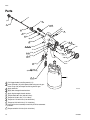
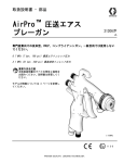
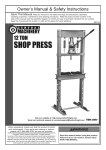
Instructions - Parts List
RAZOR® Siphon
Feed Gun
312106F
ENG
A premier gun for the automotive refinish market for use with thin to medium viscosity
materials (14-20 seconds Zahn #2 cup). If spraying heavier materials, use a pressure or
gravity feed spray gun.
Includes HVLP, Compliant, and Conventional Series.
See page 2 for List of Models and maximum working pressures.
See page 10 for Parts.
Important Safety Instructions
Read all warnings and instructions in this
manual. Save these instructions.
This manual is available in the following languages.
English
Spanish
French
German
Italian
312106
312107
312108
312109
312110
Contents
Models . . . . . . . . . . . . . . . . . . . . . . . . . . . . . . . . . . . . 2
Warnings . . . . . . . . . . . . . . . . . . . . . . . . . . . . . . . . . . 3
Setup . . . . . . . . . . . . . . . . . . . . . . . . . . . . . . . . . . . . . 4
Operation . . . . . . . . . . . . . . . . . . . . . . . . . . . . . . . . . 4
Maintenance . . . . . . . . . . . . . . . . . . . . . . . . . . . . . . . 5
Repair . . . . . . . . . . . . . . . . . . . . . . . . . . . . . . . . . . . . 6
Troubleshooting . . . . . . . . . . . . . . . . . . . . . . . . . . . . 7
Technical Data . . . . . . . . . . . . . . . . . . . . . . . . . . . . . 8
Accessories . . . . . . . . . . . . . . . . . . . . . . . . . . . . . . . 9
Parts . . . . . . . . . . . . . . . . . . . . . . . . . . . . . . . . . . . . 10
Graco Standard Warranty . . . . . . . . . . . . . . . . . . . 12
Graco Information . . . . . . . . . . . . . . . . . . . . . . . . . 12
TI8222A
II 2 G
Models
Models
Part
Number Series
Spray Type
Max HVLP/
Comp
Pressure psi Nozzle
(MPa, bar)
(mm)
Application
Air Cap
Nozzle
Needle
Assy
Needle
Tip
Air Cap
with
Retaining
Ring
288588
A
HVLP
30 (0.21, 2.1)
2.2
Clear, Base
253827
253778 253777 234779
289504
288589
A
Compliant
35 (0.24, 2.4)
1.0
Clear, Base
288454
288301 288640 288751
289510
288590
A
Compliant
35 (0.24, 2.4)
1.2
Clear, Base
288454
288302 288641 234778
289510
288591
A
Compliant
35 (0.24, 2.4)
1.3
Clear, Base
288454
288303 288641 234778
289510
288592
A
Compliant
35 (0.24, 2.4)
1.4
Clear, Base
288454
288304 288642 288752
289510
288593
A
Compliant
35 (0.24, 2.4)
1.6
Clear, Base
288454
288305 288642 288752
289510
288594
A
Compliant
35 (0.24, 2.4)
1.8
Primer
288454
288306 288643 253917
289510
288595
A
Conventional
N/A
1.5
Clear, Base
288455
288307 288642 288752
289511
288596
A
Conventional
N/A
1.8
Clear, Base
288455
288308 288642 288752
289511
288597
A
Conventional
N/A
2.0
Primer
288456
288309 253777 234779
289512
288598
A
Conventional
N/A
2.5
Primer
288457
288310 253777 234779
289513
Needle Tips
Grooves
Needle Tip
0
234779
3
288751
4
288752
6
234778
7
253917
Grooves
ti14043a
2
312106F
Warnings
Warnings
The following warnings are for the setup, use, grounding, maintenance, and repair of this
equipment. The exclamation point symbol alerts you to a general warning and the hazard
symbols refer to procedure-specific risks. Refer back to these warnings. Additional, productspecific warnings may be found throughout the body of this manual where applicable.
WARNING
FIRE AND EXPLOSION HAZARD
Flammable fumes, such as solvent and paint fumes, in work area can ignite or explode.
To help prevent fire and explosion:
• Use equipment only in well ventilated area.
• Eliminate all ignition sources; such as pilot lights, cigarettes, portable electric
lamps, and plastic drop cloths (potential static arc).
• Keep work area free of debris, including solvent, rags and gasoline.
• Do not plug or unplug power cords or turn lights on or off when flammable fumes
are present.
• Ground all equipment in the work area. See Grounding instructions.
• If there is static sparking or you feel a shock, stop operation immediately. Do not
use equipment until you identify and correct the problem.
• Keep a working fire extinguisher in the work area.
PRESSURIZED EQUIPMENT HAZARD
Fluid from the gun/dispense valve, leaks, or ruptured components can splash in the
eyes or on skin and cause serious injury.
• Follow Pressure Relief Procedure in this manual, when you stop spraying and
before cleaning, checking, or servicing equipment.
• Tighten all fluid connections before operating the equipment.
• Check hoses, tubes, and couplings daily. Replace worn or damaged parts
immediately.
EQUIPMENT MISUSE HAZARD
Misuse can cause death or serious injury.
• Do not exceed the maximum working pressure or temperature rating of the lowest
rated system component. See Technical Data in all equipment manuals.
• Use fluids and solvents that are compatible with equipment wetted parts. See
Technical Data in all equipment manuals. Read fluid and solvent manufacturer’s
warnings.
• Check equipment daily. Repair or replace worn or damaged parts immediately.
• Do not alter or modify equipment.
• Use equipment only for its intended purpose. Call your Graco distributor for
information.
• Route hoses and cables away from traffic areas, sharp edges, moving parts, and
hot surfaces.
• Do not kink or overbend hoses or use hoses to pull equipment.
• Keep children and animals away from work area.
• Comply with all applicable safety regulations.
312106F
3
Setup
WARNING
PERSONAL PROTECTIVE EQUIPMENT
You must wear appropriate protective equipment when operating, servicing, or when in
the operating area of the equipment to help protect you from serious injury, including
eye injury, inhalation of toxic fumes, burns, and hearing loss. This equipment includes
but is not limited to:
• Protective eyewear
• Clothing and respirator as recommended by the fluid and solvent manufacturer
• Gloves
• Hearing protection
Setup
•
Check that your shop air provides
adequate air flow.
•
Use a minimum 3/8 in. (10 mm) ID air
hose.
•
Set shop air pressure regulator (not
supplied) according to paint manufacturer’s recommendation. See
maximum pressures and compliant
air pressures on page 2.
•
Make sure no air restrictions, such as
low-volume cheater-valves, obstruct
the air flow. If an air adjusting valve is
desired, use a Graco Air Adjusting
Valve (288744 or 234387).
•
Install a shutoff valve (not supplied)
downstream of the air regulator to
shut off gun air.
•
Install an inline air filter (not supplied)
to clean and dry the gun air supply.
1. Shut off the air supply.
2. Connect a clean, dry, filtered air supply to
the air inlet fitting (25). See page 10.
3. If this is the first time using the equipment,
flush the gun. See page 5.
Operation
Pressure Relief Procedure
1. Turn off the gun air supply.
2. Trigger the gun to relieve pressure.
Spraying
CAUTION
Excessive atomizing air pressure can
increase over-spray, reduce transfer
efficiency, and result in a poor quality finish.
Regulatory agencies in certain states
prohibit the operation of a spray gun above
10 psi (69 kPa, 0.7 bar) atomizing air cap
pressure.
1. Fill the cup with material. Do not fill past the
shoulder on cup.
2. Turn on the shop air to the gun and set
atomizing pressure with the gun fully
triggered.
3. Adjust the pattern size and shape with the
fluid adjust knob (8). Fluid adjust knob (8) is
factory set for maximum needle trigger
travel and material flow. Turn knob
clockwise to reduce pattern size/ fluid flow
and counterclockwise to increase it.
See Troubleshooting, page 7, if you experience an irregular pattern.
4
312106F
Maintenance
Volatile Organic Compounds
(VOC) Regulation
Cleaning Gun and Cup
In certain states, spraying solvents that release
VOCs into the atmosphere when cleaning
a spray gun is prohibited. To comply with these
air quality laws, you must use a cleaning
method that prevents the escape of VOC
vapors into the atmosphere. See Compliant
Cleaning Methods, page 5
•
•
•
CAUTION
Do not submerge gun in solvent. Solvent
dissolves lubricant, dries out packings,
and clogs air passages.
Do not use metal tools to clean air cap
holes as this may scratch them and distort
the spray pattern.
Use a compatible solvent.
.
Clean air line filters as directed by the
manufacturer.
Maintenance
1. Flush, page 5.
2. Use a rag moistened in solvent to wipe
outside of gun and cup.
3. Make sure cup lid vent hole is clear.
4. Blow dry gun inside and out. Lubricate, see
Maintenance, page 5.
•
Frequently lubricate the gun moving
parts with a drop of non-silicone oil.
•
Do not disassemble the spray gun if you
are having a spray pattern problem. See
Troubleshooting, page 7, for information
on how to correct the problem.
•
Check for fluid leakage. Tighten fittings
or replace equipment as needed.
Flush
Flush before using the equipment, before
changing colors, and when you are done
spraying. Use solvent that is compatible with
gun wetted parts and fluid that will be sprayed.
See Compliant Cleaning Methods, page 5,
to comply with air quality laws if applicable.
1. Relieve pressure, page 4.
2. Dispose of any paint in the cup.
See Compliant Cleaning Methods, page 5,
to comply with air quality laws if applicable.
Cleaning Nozzle and Air Cap
1. Remove air cap (13), trigger gun, remove
nozzle (11), and soak both in a compatible
cleaning solution.
2. Clean them and the front of the gun with
a soft-bristle brush dipped into compatible
solvent. Do not use a wire brush or metal
tools.
3. Use a soft implement, such as a toothpick
to clean out air cap holes.
Compliant Cleaning Methods
1. Place spray gun in a gun washer that completely encloses the gun and components
during cleaning, rinsing, and draining.
3. Fill the cup with a small amount of solvent.
4. Spray into a grounded metal waste
container until the equipment is clean.
2. Spray solvent through the spray gun into
a closed gun cleaning station.
5. Relieve pressure, page 4.
312106F
5
Repair
Repair
See Parts, page 10, for callout references.
Needle Replacement
1. Remove knob (8), spring (29), and needle
(9). Inspect. Replace tip (9a) or needle (9)
as necessary. See page 2.
2. Insert needle (9), spring (29), and knob (8).
4. Inspect u-cup seals (22) and replace if
necessary.
5. Lubricate gun as described in Maintenance, page 5.
6. Insert replacement air valve assembly (6).
Replace spring (31) and nut (7).
Nozzle Replacement
7. Replace trigger (10), wave washer (18),
trigger pin (23), trigger nut (24), needle (9),
spring (29), and knob (8).
1. Unscrew retaining ring (14) to remove air
cap assembly (13).
Needle Packing Replacement
2. Trigger gun while unscrewing nozzle (11) to
prevent needle damage.
1. Remove trigger nut (24), trigger pin (23),
wave washer (18), and trigger (10).
3. Check o-ring (21) and replace if necessary.
2. Remove knob (8), spring (29), and needle (9).
4. Trigger gun while replacing nozzle (11).
3. Unscrew nut (17) and remove u-cup (16)
and spreader (15).
5. Insert air cap assembly (13) into gun.
6. Screw retaining ring (14) into place.
Air Control Valve Replacement
1. Remove air control valve assembly (5).
4. Insert replacement spreader (15) facing
back of gun, u-cup (16) facing front of gun,
and nut (17).
5. Replace trigger (10), wave washer (18),
trigger pin (23), trigger nut (24), needle (9),
spring (29), and knob (8).
2. Insert replacement assembly (5) into gun.
Air Valve Replacement
1. Remove trigger nut (24), trigger pin (23),
wave washer (18), and trigger (10).
2. Remove knob (8), spring (29), needle (9)
and nut (7).
3. Remove spring (31) and push the air valve
assembly (6) out the back of the gun.
6
312106F
Troubleshooting
Troubleshooting
Problem
Cause
Normal pattern.
Solution
No action necessary.
Dirty or damaged air cap or fluid
nozzle.
Rotate air cap 180°.
Right
Wrong
Heavy top
or bottom
pattern
Pressure too high for viscosity of
material being sprayed.
If pattern does not follow the air cap, the
problem is with the fluid nozzle. Clean
and inspect the nozzle. If the pattern is
not corrected, replace nozzle.
Reduce air pressure and increase
material viscosity.
Correct pattern by narrowing fan size with
spray width adjustment knob (8).
Wrong
Split pattern
Wrong
Gun spitting
If pattern follows air cap, problem is in air
cap (13). Clean and inspect. If pattern is
not corrected, replace air cap.
Dirty or distorted air horn holes.
Clean and inspect air cap. If pattern is not
corrected, replace air cap.
Air getting into paint stream.
Check if cup is empty and fill.
Tighten fluid nozzle (11).
Check and tighten needle packing nut (17).
Will not spray
Excessive air
blowing back
312106F
Cup is empty.
Fluid adjustment knob (8) turned
too far clockwise.
Loose fluid nozzle (11).
Damaged fluid nozzle seal (21).
Check fluid nozzle (11) for damage.
Fill cup.
Adjust knob (8) counterclockwise.
Tighten fluid nozzle (11).
Replace seal (21).
7
Technical Data
Technical Data
Maximum Air Inlet Pressure . . . . . . . . . . . . . . . . . . . . . .
Maximum HVLP/Compliant Inbound Air Pressure
HVLP. . . . . . . . . . . . . . . . . . . . . . . . . . . . . . . . . . . . . . . .
Compliant . . . . . . . . . . . . . . . . . . . . . . . . . . . . . . . . . . . .
Air Consumption
HVLP. . . . . . . . . . . . . . . . . . . . . . . . . . . . . . . . . . . . . . . .
Compliant . . . . . . . . . . . . . . . . . . . . . . . . . . . . . . . . . . . .
Conventional . . . . . . . . . . . . . . . . . . . . . . . . . . . . . . . . . .
Fluid and Air Operating Temperature Range. . . . . . . . .
Spray Gun:
Air Inlet . . . . . . . . . . . . . . . . . . . . . . . . . . . . . . . . . . . . . .
Fluid Inlet. . . . . . . . . . . . . . . . . . . . . . . . . . . . . . . . . . . . .
Weight with cup . . . . . . . . . . . . . . . . . . . . . . . . . . . . . . . .
Sound Data:
HVLP sound pressure at 30 psi (0.21 MPa, 2.1 bar). . . .
HVLP sound power at 30 psi (0.21 MPa, 2.1 bar). . . . . .
Compliant sound pressure at 35 psi (0.24 MPa, 2.4 bar)
Compliant sound power at 35 psi (0.24 MPa, 2.4 bar) . .
Conventional sound pressure at 43 psi (0.3 MPa, 3.0 bar)
Conventional sound power at 43 psi (0.3 MPa, 3.0 bar) .
Siphon Cup Size . . . . . . . . . . . . . . . . . . . . . . . . . . . . . . . .
Wetted Parts . . . . . . . . . . . . . . . . . . . . . . . . . . . . . . . . . . .
100 psi (0.7 MPa, 7 bar)
30 psi (0.21 MPa, 2.1 bar)
35 psi (0.24 MPa, 2.4 bar)
11.2 CFM at 30 psi (0.21 MPa, 2.1 bar)
10.4 CFM at 35 psi (0.24 MPa, 2.4 bar)
12.2 CFM at 43 psi (0.3 MPa, 3.0 bar)
32°F to 109°F (0°C to 43°C)
1/4 npsm (R1/4-19)
3/8 npsm (R3/8-19)
2.1 lbs (1.0 kg)
81.8 dB(A)**
88.7 dB(A)**
74.68 dB(A)**
83.07 dB(A)**
78.22 dB(A)**
86.68 dB(A)**
1 qt. (0.95 liter)
303 SST, 17-4 PH SST, PEEK, acetal,
UHMWPE
Produces 10 psi (0.07 MPa, 0.7 bar) spraying pressure at air cap.
** All readings were taken with the fan valve fully open (fan full size) at the assumed operator
position. Sound power was tested per ISO 9614-2.
*
8
312106F
Accessories
Accessories
Repair Kits
Part No.
253748
253783
253784
253785
253933
253934
24C269
24C310
Description
Needle Packing Repair Kit
Gun Repair Kit
Air Cap Seal Kit
Trigger Repair Kit
Air Inlet Fitting Repair Kit
Air Valve Repair Kit
Fluid Inlet Fitting Kit
Nozzle O-Ring Kit, 5-Pack
Air Valves
Part No.
288744
234387
Description
High Volume Air Adjusting Valve with Gauge
High Output Precision Air Valve
Test Gauges
Part No.
253747
312106F
Description
HVLP Verification
9
Parts
Parts
9
‡8
3
7‡
8
‡29
5
4
6
10
1
18**
23**
9a
3
3 *‡22
3
‡31
*‡6
3
4
3
21*
*‡22
7
**24
3
2
*†16
2
*†15
1
9
19*◆✓
13✓
17
3
11
2*
3
11
5
*◆✓20
14✓
11
^25
10**
11 ^30a
(sold separately)
10 11
1
2
3
4
5
6
7
8
9
10
11
10
30
Pull trigger before installing nozzle (11).
Insert spreader (15) with tapered end facing rear of gun.
Insert u-cup (16) with open end facing front of gun.
Apply lubricant.
Apply low strength thread retainer.
Apply high strength thread retainer.
Torque to 85-90 in-lbs (9.6-10.2 N•m).
Torque to 15-20 in-lbs (1.7-2.2 N•m).
Torque to 175-185 in-lbs (19.8-20.9 N•m).
Torque to 155-165 in-lbs (17.5-18.6 N•m).
Install with valve assembly turned fully CCW to outermost
position.
Torque to 205-215 in-lbs (23.2-24.3 N•m).
37
TI8223b
312106F
Parts
Ref.
No.
1
2*✠
3✠
5
6*‡
7‡
8‡
9
9a
10**
11
13✓
14✓
15*†
16*†
17
18**
19*◆✓
20*◆✓
21*
22*‡
23**
24**
25^
28*
29‡
30
30a^
31‡
32
36*‡
37
312106F
Part No.Description
Qty.
--- BODY, gun
1
--- GASKET, fluid inlet
1
--- FITTING, fluid inlet
1
253976 VALVE, air control, assy
1
--- VALVE, air, assy
1
--- NUT
1
--- KNOB, fluid adjust
1
page 2 NEEDLE (includes 9a)
1
page 2 TIP, needle
1
--- TRIGGER
1
page 2 NOZZLE (includes 21)
1
page 2 AIR CAP
1
253970 RING, retaining
1
--- SPREADER, needle packing
1
--- U-CUP, needle packing
1
253972 NUT, needle packing
1
--- WASHER, wave
1
--- O-RING, PTFE
1
--- WASHER, UHMWPE
1
--- O-RING, PTFE
1
--- PACKING, u-cup
2
--- PIN, trigger
1
--- NUT, trigger
1
--- FITTING, air inlet
1
--- WASHER, UHMWPE (not shown)
1
--- SPRING, fluid
1
253979 VALVE, air inlet adjustment
1
289452 PLUG, air inlet (sold separately)
1
--- SPRING, air valve
1
253974 TOOL, gun (not shown)
1
--- TOOL, seal installation (not shown) 1
244130 CUP, siphon, aluminum
1
*
Included in Gun Repair Kit 253783 (purchase
separately).
** Included in Trigger Repair Kit 253785 (purchase
separately).
† Included in Needle Packing Repair Kit 253748
(purchase separately).
‡ Included in Air Valve Repair Kit 253934 (purchase
separately).
◆ Included in Air Cap Seal Kit 253784 (purchase
separately).
^ Included in Air Inlet Fitting Repair Kit 253933
(purchase separately).
✓ Included in Air Cap with Retaining Kit (purchase
separately). See page 2.
✠ Included in Fluid Inlet Fitting Kit 24C269 (purchase
separately).
--- Not sold separately.
11
Graco Standard Warranty
Graco warrants all equipment referenced in this document which is manufactured by Graco and bearing its name to be free from defects in
material and workmanship on the date of sale to the original purchaser for use. With the exception of any special, extended, or limited warranty
published by Graco, Graco will, for a period of twelve months from the date of sale, repair or replace any part of the equipment determined by
Graco to be defective. This warranty applies only when the equipment is installed, operated and maintained in accordance with Graco’s written
recommendations.
This warranty does not cover, and Graco shall not be liable for general wear and tear, or any malfunction, damage or wear caused by faulty
installation, misapplication, abrasion, corrosion, inadequate or improper maintenance, negligence, accident, tampering, or substitution of
non-Graco component parts. Nor shall Graco be liable for malfunction, damage or wear caused by the incompatibility of Graco equipment with
structures, accessories, equipment or materials not supplied by Graco, or the improper design, manufacture, installation, operation or
maintenance of structures, accessories, equipment or materials not supplied by Graco.
This warranty is conditioned upon the prepaid return of the equipment claimed to be defective to an authorized Graco distributor for verification of
the claimed defect. If the claimed defect is verified, Graco will repair or replace free of charge any defective parts. The equipment will be returned
to the original purchaser transportation prepaid. If inspection of the equipment does not disclose any defect in material or workmanship, repairs will
be made at a reasonable charge, which charges may include the costs of parts, labor, and transportation.
THIS WARRANTY IS EXCLUSIVE, AND IS IN LIEU OF ANY OTHER WARRANTIES, EXPRESS OR IMPLIED, INCLUDING BUT NOT LIMITED
TO WARRANTY OF MERCHANTABILITY OR WARRANTY OF FITNESS FOR A PARTICULAR PURPOSE.
Graco’s sole obligation and buyer’s sole remedy for any breach of warranty shall be as set forth above. The buyer agrees that no other remedy
(including, but not limited to, incidental or consequential damages for lost profits, lost sales, injury to person or property, or any other incidental or
consequential loss) shall be available. Any action for breach of warranty must be brought within two (2) years of the date of sale.
GRACO MAKES NO WARRANTY, AND DISCLAIMS ALL IMPLIED WARRANTIES OF MERCHANTABILITY AND FITNESS FOR A
PARTICULAR PURPOSE, IN CONNECTION WITH ACCESSORIES, EQUIPMENT, MATERIALS OR COMPONENTS SOLD BUT NOT
MANUFACTURED BY GRACO. These items sold, but not manufactured by Graco (such as electric motors, switches, hose, etc.), are subject to
the warranty, if any, of their manufacturer. Graco will provide purchaser with reasonable assistance in making any claim for breach of these
warranties.
In no event will Graco be liable for indirect, incidental, special or consequential damages resulting from Graco supplying equipment hereunder, or
the furnishing, performance, or use of any products or other goods sold hereto, whether due to a breach of contract, breach of warranty, the
negligence of Graco, or otherwise.
FOR GRACO CANADA CUSTOMERS
The Parties acknowledge that they have required that the present document, as well as all documents, notices and legal proceedings entered into,
given or instituted pursuant hereto or relating directly or indirectly hereto, be drawn up in English. Les parties reconnaissent avoir convenu que la
rédaction du présente document sera en Anglais, ainsi que tous documents, avis et procédures judiciaires exécutés, donnés ou intentés, à la suite
de ou en rapport, directement ou indirectement, avec les procédures concernées.
Graco Information
For the latest information about Graco products, visit www.graco.com.
TO PLACE AN ORDER, contact your Graco distributor or call to identify the nearest distributor.
Phone: 612-623-6921 or Toll Free: 1-800-328-0211 Fax: 612-378-3505
All written and visual data contained in this document reflects the latest product information available at the time of publication.
Graco reserves the right to make changes at any time without notice.
This manual contains English. MM 312106
Graco Headquarters: Minneapolis
International Offices: Belgium, China, Japan, Korea
GRACO INC. P.O. BOX 1441 MINNEAPOLIS, MN 55440-1441
Copyright 2008, Graco Inc. is registered to ISO 9001
www.graco.com
Revised 09/2009