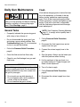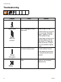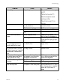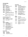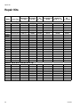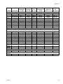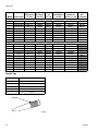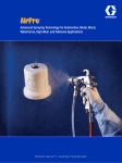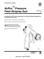
1
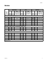
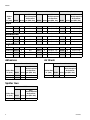
Instructions-Parts
™
AirPro
Pressure
Feed Airspray Gun
312414J
ENG
Conventional, HVLP, and compliant guns for specialty industrial applications.
For professional use only.
100 psi (0.7 MPa, 7 bar) Maximum Air Inlet Pressure
300 psi (2.1 MPa, 21 bar) Maximum Fluid Inlet Pressure
Important Safety Instructions
Read all warnings and instructions in
this manual. Save these instructions.
See page 3 for model information.
ti11094a
ll 2 G
Related Manuals
Contents
Related Manuals . . . . . . . . . . . . . . . . . . . . . . . . . . .
Models . . . . . . . . . . . . . . . . . . . . . . . . . . . . . . . . . . .
General Metal Spray Guns . . . . . . . . . . . . . . . . .
General Metal with Stainless Steel Tip . . . . . . . .
Automotive . . . . . . . . . . . . . . . . . . . . . . . . . . . . .
Stain . . . . . . . . . . . . . . . . . . . . . . . . . . . . . . . . . .
Waterborne . . . . . . . . . . . . . . . . . . . . . . . . . . . . .
High Wear . . . . . . . . . . . . . . . . . . . . . . . . . . . . . .
Adhesives . . . . . . . . . . . . . . . . . . . . . . . . . . . . . .
Spatter Gun . . . . . . . . . . . . . . . . . . . . . . . . . . . . .
Air Brush . . . . . . . . . . . . . . . . . . . . . . . . . . . . . . .
Warnings . . . . . . . . . . . . . . . . . . . . . . . . . . . . . . . . .
Gun Selection . . . . . . . . . . . . . . . . . . . . . . . . . . . . .
Conventional Guns . . . . . . . . . . . . . . . . . . . . . . .
HVLP Guns . . . . . . . . . . . . . . . . . . . . . . . . . . . . .
Compliant Guns . . . . . . . . . . . . . . . . . . . . . . . . .
Setup . . . . . . . . . . . . . . . . . . . . . . . . . . . . . . . . . . . . .
Connect Air and Fluid Lines . . . . . . . . . . . . . . . .
Ground the Gun . . . . . . . . . . . . . . . . . . . . . . . . .
Flush Before Using Equipment . . . . . . . . . . . . . .
Adjust Spray Pattern . . . . . . . . . . . . . . . . . . . . . .
2
3
3
3
3
4
4
4
4
4
4
5
6
6
6
6
7
7
7
7
8
Operation . . . . . . . . . . . . . . . . . . . . . . . . . . . . . . . . . 9
Pressure Relief Procedure . . . . . . . . . . . . . . . . . 9
Apply Fluid . . . . . . . . . . . . . . . . . . . . . . . . . . . . . . 9
Volatile Organic Compounds (VOC) Regulation . 9
Daily Gun Maintenance . . . . . . . . . . . . . . . . . . . . . 10
General Tasks . . . . . . . . . . . . . . . . . . . . . . . . . . 10
Flush . . . . . . . . . . . . . . . . . . . . . . . . . . . . . . . . . 10
Clean Gun . . . . . . . . . . . . . . . . . . . . . . . . . . . . . 11
Compliant Cleaning Methods . . . . . . . . . . . . . . 11
Troubleshooting . . . . . . . . . . . . . . . . . . . . . . . . . . . 12
Repair . . . . . . . . . . . . . . . . . . . . . . . . . . . . . . . . . . . 14
Disassembly . . . . . . . . . . . . . . . . . . . . . . . . . . . 14
Reassembly . . . . . . . . . . . . . . . . . . . . . . . . . . . . 15
Parts . . . . . . . . . . . . . . . . . . . . . . . . . . . . . . . . . . . . 16
Accessories . . . . . . . . . . . . . . . . . . . . . . . . . . . . . . 19
Repair Kits . . . . . . . . . . . . . . . . . . . . . . . . . . . . . . . 20
Technical Data . . . . . . . . . . . . . . . . . . . . . . . . . . . . 23
Graco Standard Warranty . . . . . . . . . . . . . . . . . . . 24
Graco Information . . . . . . . . . . . . . . . . . . . . . . . . . 24
Related Manuals
2
Manual
Language
313059
Chinese
313061
Dutch
313062
Finnish
313063
French
313064
German
313066
Italian
313067
Japanese
313068
Korean
313070
Portuguese
313071
Russian
313072
Spanish
313073
Swedish
312414J
Models
Models
Conventional
Orifice
Size
in. (mm)
HVLP
Compliant
Max.
Max.
Max.
HVLP/Compliant
HVLP/Compliant
HVLP/Compliant
Air Pressure
Air Pressure
Air Pressure
Model Series psi (MPa, bar) Model Series psi (MPa, bar) Model Series psi (MPa, bar)
General Metal Spray Guns
0.020 (0.5) 288726
A
N/A
288935
A
19 (0.13, 1.3)
288942
A
29 (0.2, 2.0)
0.030 (0.8) 288929
A
N/A
288936
A
19 (0.13, 1.3)
288943
A
29 (0.2, 2.0)
0.042 (1.1) 288930
A
N/A
288937
A
19 (0.13, 1.3)
288944
A
29 (0.2, 2.0)
0.055 (1.4) 288931
A
N/A
288938
A
19 (0.13, 1.3)
288945
A
29 (0.2, 2.0)
0.070 (1.8) 288932
A
N/A
288939
A
19 (0.13, 1.3)
288946
A
29 (0.2, 2.0)
0.086 (2.2) 288933
A
N/A
288940
A
19 (0.13, 1.3)
288947
A
29 (0.2, 2.0)
0.110 (2.8) 288934
A
N/A
288941
A
19 (0.13, 1.3)
288948
A
29 (0.2, 2.0)
General Metal with Stainless Steel Tip
0.042 (1.1) 288949
A
N/A
288952
A
19 (0.13, 1.3)
288955
A
29 (0.2, 2.0)
0.055 (1.4) 288950
A
N/A
288953
A
19 (0.13, 1.3)
288956
A
29 (0.2, 2.0)
0.070 (1.8) 288951
A
N/A
288954
A
19 (0.13, 1.3)
288957
A
29 (0.2, 2.0)
0.030 (0.8) 288929
A
N/A
--
--
--
--
--
--
0.040 (1.0)
--
--
289034
A
29 (0.2, 2.0)
289036
A
35 (0.24, 2.4)
0.042 (1.1) 288930
A
N/A
--
--
--
--
--
--
0.042 (1.1) 24D472*
A
N/A
--
--
--
--
--
--
0.047 (1.2)
--
--
289035
A
29 (0.2, 2.0)
289037
A
35 (0.24, 2.4)
A
N/A
289541
A
29 (0.2, 2.0)
289542
A
35 (0.24, 2.4)
Automotive
--
--
0.055 (1.4) 288931
* High production
312414J
3
Models
Conventional
Orifice
Size
in. (mm)
HVLP
Compliant
Max.
Max.
Max.
HVLP/Compliant
HVLP/Compliant
HVLP/Compliant
Air Pressure
Air Pressure
Air Pressure
Model Series psi (MPa, bar) Model Series psi (MPa, bar) Model Series psi (MPa, bar)
Stain
0.020 (0.5) 288958
A
N/A
288960
A
22 (0.15, 1.5)
288962
A
29 (0.2, 2.0)
0.030 (0.8) 288959
A
N/A
288961
A
22 (0.15, 1.5)
288963
A
29 (0.2, 2.0)
0.040 (1.0) 289109
A
N/A
289110
A
22 (0.15, 1.5)
289111
A
29 (0.2, 2.0)
0.030 (0.8) 288964
A
N/A
288967
A
23 (0.16, 1.6)
288970
A
23 (0.16, 1.6)
0.042 (1.1) 288965
A
N/A
288968
A
23 (0.16, 1.6)
288971
A
23 (0.16, 1.6)
0.055 (1.4) 288966
A
N/A
288969
A
23 (0.16, 1.6)
288972
A
23 (0.16, 1.6)
0.059 (1.5) 288973
A
N/A
288976
A
20 (0.14, 1.4)
288979
A
29 (0.2, 2.0)
0.070 (1.8) 288974
A
N/A
288977
A
20 (0.14, 1.4)
288980
A
29 (0.2, 2.0)
0.086 (2.2) 288975
A
N/A
288978
A
20 (0.14, 1.4)
288981
A
29 (0.2, 2.0)
0.110 (2.8) 289982
A
N/A
289983
A
20 (0.14, 1.4)
289984
A
29 (0.2, 2.0)
Waterborne
High Wear
Adhesives
Air Brush
Conventional
Max.
HVLP/Compliant
Air Pressure
Orifice Size
in. (mm)
Model Series psi (MPa, bar)
0.051 (1.3) 288982
A
N/A
0.070 (1.8) 288983
A
N/A
Conventional
Max.
HVLP/Compliant
Air Pressure
Orifice Size
in. (mm)
Model Series psi (MPa, bar)
0.042 (1.1) 24F202
A
N/A
Spatter Gun
HVLP
Max.
HVLP/Compliant
Air Pressure
Orifice Size
Model Series psi (MPa, bar)
in. (mm)
0.042 (1.1) 288985
4
A
30 (0.21, 2.1)
312414J
Warnings
Warnings
The following warnings are for the setup, use, grounding, maintenance, and repair of this equipment. The exclamation point symbol alerts you to a general warning and the hazard symbol refers
to procedure-specific risk. Refer back to these warnings. Additional, product-specific warnings
may be found throughout the body of this manual where applicable.
WARNING
FIRE AND EXPLOSION HAZARD
Flammable fumes, such as solvent and paint fumes, in work area can ignite or explode.
To help prevent fire and explosion:
• Use equipment only in well ventilated area.
• Eliminate all ignition sources; such as pilot lights, cigarettes, portable electric
lamps, and plastic drop cloths (potential static arc).
• Keep work area free of debris, including solvent, rags and gasoline.
• Do not plug or unplug power cords or turn lights on or off when flammable fumes
are present.
• Ground all equipment in the work area. See Grounding instructions.
• If there is static sparking or you feel a shock, stop operation immediately. Do not
use equipment until you identify and correct the problem.
• Keep a working fire extinguisher in the work area.
EQUIPMENT MISUSE HAZARD
Misuse can cause death or serious injury.
• Do not operate the unit when fatigued or under the influence of drugs or alcohol.
• Do not exceed the maximum working pressure or temperature rating of the lowest
rated system component. See Technical Data in all equipment manuals.
• Use fluids and solvents that are compatible with equipment wetted parts. See Technical Data in all equipment manuals. Read fluid and solvent manufacturer’s warnings. For complete information about your material, request MSDS forms from
distributor or retailer.
• Check equipment daily. Repair or replace worn or damaged parts immediately with
genuine manufacturer’s replacement parts only.
• Do not alter or modify equipment.
• Use equipment only for its intended purpose. Call your distributor for information.
• Route hoses and cables away from traffic areas, sharp edges, moving parts, and
hot surfaces.
• Do not kink or over bend hoses or use hoses to pull equipment.
• Keep children and animals away from work area.
• Comply with all applicable safety regulations.
312414J
5
Gun Selection
WARNING
PRESSURIZED EQUIPMENT HAZARD
Fluid from the gun/dispense valve, leaks, or ruptured components can splash in the
eyes or on skin and cause serious injury.
• Follow Pressure Relief Procedure in this manual, when you stop spraying and
before cleaning, checking, or servicing equipment.
• Tighten all fluid connections before operating the equipment.
• Check hoses, tubes, and couplings daily. Replace worn or damaged parts immediately.
TOXIC FLUID OR FUMES HAZARD
Toxic fluids or fumes can cause serious injury or death if splashed in the eyes or on
skin, inhaled, or swallowed.
• Read MSDS’s to know the specific hazards of the fluids you are using.
• Store hazardous fluid in approved containers, and dispose of it according to applicable guidelines.
• Always wear impervious gloves when spraying or cleaning equipment.
PERSONAL PROTECTIVE EQUIPMENT
You must wear appropriate protective equipment when operating, servicing, or when in
the operating area of the equipment to help protect you from serious injury, including
eye injury, inhalation of toxic fumes, burns, and hearing loss. This equipment includes
but is not limited to:
• Protective eyewear
• Clothing and respirator as recommended by the fluid and solvent manufacturer
• Gloves
• Hearing protection
Gun Selection
Conventional Guns
Compliant Guns
Excellent atomization and high production
rates typically with some reduction in transfer
efficiency.
A compliant gun is a high transfer efficiency
gun which has been tested to have a transfer
efficiency greater than or equal to HVLP guns.
The Graco compliant guns have no restrictions
on air cap pressures, but the gun inlet pressure must remain under the maximum compliant pressure shown on pages 3-4 to remain in
compliance.
HVLP Guns
An HVLP gun is a high transfer efficiency gun
which limits the air pressure at the air cap to
10 psi (0.07 MPa, 0.7 bar) maximum. In some
areas, an HVLP gun is required for compliance
with environmental standards.
6
312414J
Setup
Setup
5. Connect a fluid hose to the fluid inlet fitting.
See FIG. 1.
At least one hose must provide a static
ground to the gun.
Connect Air and Fluid Lines
1. Shut off the air supply.
2. Install a shutoff valve (not supplied) downstream of the air regulator to shut off gun
air.
3. Install an inline air filter (not supplied) to
clean and dry the gun air supply.
4. Connect a clean, dry, filtered air supply to
the air inlet fitting. See FIG. 1.
air inlet
FIG. 1
fluid inlet
ti11094a
6. Connect other end of the fluid hose to a
regulated fluid supply line.
Ground the Gun
•
Recommended 5/16 in. (7.9 mm) ID
hose, optional 3/8 in. (9.5 mm) ID hose.
•
Check that your shop air provides adequate air flow. See Technical Data,
page 23, for minimum cfm
requirements.
•
Set shop air pressure regulator (not
supplied) according to fluid manufacturer’s recommendation. See maximum
compliant air pressure on air cap.
•
312414J
Make sure no air restrictions, such as
low-volume cheater valves, obstruct the
air flow.
Check your local electrical code and pump
manual for detailed grounding instructions.
Ground the spray gun through connection to a
Graco-approved grounded fluid or air supply
hose.
Flush Before Using Equipment
The equipment was tested with lightweight oil,
which is left in the fluid passages to protect
parts. To avoid contaminating your fluid with
oil, flush the equipment with a compatible solvent before using the equipment. See Flush,
page 10.
7
Setup
Adjust Spray Pattern
1. Rotate the air cap to achieve desired spray
pattern. See FIG. 2.
7. To reduce fluid flow, turn the fluid control
valve clockwise.
•
•
ti4839a
FIG. 2
If the fluid control valve is turned clockwise all the way, the gun will emit only
air.
If you cannot achieve the correct fluid
flow with the fluid control valve, a different sized nozzle may be necessary. For
smaller fluid flow, use the next size
smaller nozzle. For a larger fluid flow,
use the next size larger nozzle.
8. Spray a test pattern. Evaluate the spray
pattern size and atomization.
2. To achieve full fan pattern, open the air
control valve by turning the knob fully counterclockwise. See FIG. 3.
9. To achieve a narrow spray pattern, turn air
control valve clockwise.
3. To create a round pattern, turn the pattern
air off by turning the air control valve fully
clockwise. See FIG. 3.
10. To improve atomization, reduce the fluid
flow rate. Increasing the air pressure can
improve atomization but may result in poor
Transfer Efficiency (TE) or non-compliant
operation.
4. Trigger gun and adjust gun air pressure.
Refer to Technical Data, page 23, for inlet
air pressure recommendations.
5. To establish the correct fluid flow, turn the
fluid control valve counterclockwise until no
restriction of the trigger movement is felt,
then turn out another half turn.
air control valve
fluid control valve
air inlet valve
ti11097a
FIG. 3
6. Adjust fluid pressure to achieve desired
fluid flow rate.
8
312414J
Operation
Operation
Pressure Relief Procedure
NOTE: See Troubleshooting, page 12, if
you experience an irregular pattern.
1. Turn off air and fluid supply.
When using the HVLP spray gun, instead of a
conventional airspray gun, you may need to
use a slightly slower hand movement and
make fewer passes with the gun to coat a part.
This is due to the reduced spray velocity produced by lower HVLP air pressures, along with
a larger fluid particle size because there is less
air to blow off solvents than is produced by
conventional airspray. Take care to avoid runs
or sags as you spray.
2. Hold a metal part of the gun firmly to a
grounded metal pail. Trigger the gun to
relieve pressure.
Volatile Organic Compounds
(VOC) Regulation
Trapped air can cause the pump to cycle
unexpectedly, which could result in serious
injury from splashing or moving parts.
Apply Fluid
CAUTION
Excessive atomizing air pressure can
increase overspray, reduce transfer efficiency, and result in a poor quality finish.
Regulatory agencies in some states prohibit
the operation of a spray gun above 10 psi
(69 kPa, 0.7 bar) atomizing air cap pressure.
In certain states, spraying solvents that release
VOCs into the atmosphere when cleaning a
spray gun is prohibited. To comply with these
air quality laws, you must use a cleaning
method that prevents the escape of VOC
vapors into the atmosphere. See Compliant
Cleaning Methods, page 11.
1. Turn on shop air and fluid supply to the
gun. Set atomizing pressure and fluid pressure with the gun fully triggered.
2. Adjust the pattern size and shape. See
page 8.
3. To achieve the best results when applying
fluid:
•
Keep the gun perpendicular and
6 to 8 inches (150 to 200 mm) from object
being sprayed.
•
Use smooth, parallel strokes across the
surface to be sprayed with 50% overlap.
312414J
9
Daily Gun Maintenance
Daily Gun Maintenance
Follow Pressure Relief Procedure, page 9,
when you stop spraying and before cleaning,
checking, servicing, or transporting equipment. Read Warnings, page 5.
General Tasks
•
Frequently lubricate the gun moving parts
with a drop of non-silicone oil.
•
Do not disassemble the spray gun if you
are having a spray pattern problem. See
Troubleshooting, page 12, for information
on how to correct the problem.
Flush
Flush before changing colors, before fluid can
dry in the equipment, at the end of the day,
before storing, and before repairing equipment. Flush at the lowest pressure possible.
Check connectors for leaks and tighten as necessary. Flush with a fluid that is compatible
with the fluid being dispensed and the equipment wetted parts.
NOTE: See Compliant Cleaning Methods,
page 11, to comply with air quality laws if
applicable.
1. Follow Pressure Relief Procedure,
page 9.
2. Disconnect the fluid supply hose and air
supply hose from gun.
•
Follow the Pressure Relief Procedure,
page 9.
3. Connect the solvent supply hose to the
gun.
•
Clean the fluid and air line filters daily.
4. Start the pump. Always use the lowest possible fluid pressure when flushing.
•
Check for any fluid leakage from gun and
fluid hoses.
CAUTION
Solvent left in gun air passages could result
in a poor quality paint finish. Do not use any
cleaning method that may allow solvent into
the gun air passages.
•
•
•
10
Do not point gun up while cleaning it.
Do not wipe gun with a cloth soaked in
solvent; wring out the excess.
Do not immerse the gun in solvent.
5. Hold a metal part of the gun firmly to a
grounded metal pail. Trigger the gun until
clean solvent dispenses.
6. Turn off solvent supply.
7. Follow Pressure Relief Procedure,
page 9,
8. Disconnect the solvent supply hose from
the gun.
312414J
Daily Gun Maintenance
Clean Gun
CAUTION
• Do not submerge gun in solvent. Solvent
dissolves lubricant, dries out packings, and
clogs air passages.
• Do not use metal tools to clean air cap
holes as this may scratch them and distort
the spray pattern.
• Use a compatible solvent.
1. Flush, page 10.
2. Remove air cap. Trigger gun, remove nozzle, and soak both in a compatible solution.
CAUTION
Trigger the gun whenever you tighten or
remove the nozzle. This keeps the needle tip
away from the nozzle seating surface and
prevents the tip from being damaged.
3. Dip the end of a soft-bristle brush into a
compatible solvent. Do not continuously
soak the brush's bristles with solvent and
do not use a wire brush.
6. Trigger the gun while you install the fluid
nozzle with the gun tool. Tighten the nozzle
securely to 155-165 in-lb (17.5-18.6 N•m)
to obtain a good seal.
7. Install the retaining ring (14) and
air cap (13b).
8. Dampen a soft cloth with solvent and wring
out the excess. Point the gun down and
wipe off the outside of the gun.
9. After cleaning the gun, lubricate the following parts with lubricant 111265 daily:
•
•
•
fluid control valve threads
trigger pivot pin
fluid needle shaft
Compliant Cleaning Methods
1. Place spray gun in a gun washer that completely encloses gun and components during cleaning, rinsing, and draining.
2. Spray solvent through the spray gun into a
closed gun cleaning station.
4. With the gun pointed down, clean the front
of the gun, using a soft-bristle brush and
solvent.
5. Scrub the air cap retaining ring, air cap,
and fluid nozzle with the soft-bristle brush.
•
•
•
312414J
To clean out air cap holes, use a soft
implement, such as a toothpick, to
avoid damaging critical surfaces.
Clean the air cap and fluid nozzle daily,
minimum. Some applications require
more frequent cleaning.
Do not soak the air cap retaining ring in
solvent for prolonged periods of time.
11
Troubleshooting
Troubleshooting
Problem
Spray Pattern
Right
Spray Pattern
Cause
Solution
Normal pattern.
No action necessary.
Dirty or damaged air cap or
fluid nozzle.
Rotate air cap (13) 180°.
If pattern follows air cap, problem is in air cap. Clean and
inspect. If pattern is not corrected, replace air cap.
Wrong
Heavy top
or bottom
Spray Pattern
If pattern does not follow the air
cap, the problem is with the
fluid nozzle (11). Clean and
inspect the nozzle. If the pattern is not corrected, replace
nozzle.
Pressure too high for viscosity Reduce air pressure and
of material being sprayed.
increase material viscosity.
Correct pattern by narrowing
fan size with the fluid control
valve (8).
Wrong
Split pattern
Spray Pattern
Dirty or distorted air horn
holes.
Clean and inspect air cap (13).
If pattern is not corrected,
replace air cap.
Wrong
12
312414J
Troubleshooting
Problem
Gun spitting.
Cause
Air getting into paint stream.
Solution
Check if fluid source is empty
and fill.
Tighten fluid nozzle (11).
Check and tighten needle
packing nut (9a).
Will not spray.
Excessive air blowing back.
Excessive air leak behind
trigger.
Fluid control valve (8) turned
too far clockwise.
Fluid source empty.
Loose fluid nozzle (11).
Damaged fluid nozzle seal
(19).
Worn u-cups/air valve.
Using needle/nozzle kit with
too small orifice.
Repair gun (Kit 289407). Be
sure to use all included parts.
Replace trigger (part 289140).
If leak persists repair gun (Kit
289407).
Use needle/nozzle kit with
larger orifice.
Using needle/nozzle kit with
too large orifice.
Use needle/nozzle kit with
smaller orifice.
Worn trigger.
Gun fluid pressure is too high
with gun triggered (cannot
achieve desired flow rate).
Using a low fluid pressure setting, the fluid flow is too high,
making it necessary to restrict
needle travel to reduce fluid
flow.
Fluid system will not operate at
low enough pressure [below
10 psi (70 kPa, 0.7 bar)].
Fluid flow is fluttering while
spraying.
There is no fluid regulator, or
air regulator is not sensitive
enough at low pressure.
Fluid filter clogged.
Fluid source empty.
Fluid flow fades while spraying Air hose size is too restricted
high viscosity fluids.
for higher air flow being used.
312414J
Check fluid nozzle (11) for
damage.
Adjust fluid control valve (8)
counterclockwise.
Refill.
Tighten fluid nozzle (11).
Replace seal (19).
Add low pressure fluid regulator, or add more sensitive low
pressure air regulator.
Check fluid filter.
Refill.
Use 5/16 in. (7.9 mm) I.D. air
hose if the hose is 25 ft (7.6 m)
long. If longer hose is needed,
use a 3/8 in. (9.5 mm) I.D.
hose.
13
Repair
Repair
Follow Pressure Relief Procedure, page 9.
See Parts, page 16, for callout references.
Disassembly
1. Unscrew retaining ring (14) to remove air
cap (13b). Check o-rings (13a and 13c)
and replace if necessary.
2. Trigger gun while unscrewing nozzle (11) to
prevent needle damage.
3. Check o-ring (19) and replace if necessary.
4. Remove fluid control valve (8), spring (26),
needle (9), and nut (7). Inspect. Replace
tip (9c), needle (9), and u-cup seal (20) as
necessary. If replacing needle tip, use low
strength thread adhesive on needle tip
threads.
5. Remove spring (28) and push the air valve
assembly (6) out the back of the gun.
Inspect. Replace air valve assembly (6)
and u-cup seal (20) as necessary. Use
tool (33) to install u-cup seal.
14
6. Remove trigger nut (22), trigger pin (21),
wave washer (18), and trigger (10).
7. Unscrew needle packing nut (17) and
remove u-cup packing (16) and
spreader (15).
8. Remove air control valve assembly (5).
Inspect and replace as necessary.
9. Remove air inlet valve assembly (27).
Inspect and replace as necessary.
NOTE: Do not remove the fluid inlet fitting.
It was attached to the gun body with permanent thread locker. There is also no
need to remove the air inlet fitting.
312414J
Repair
Reassembly
1. Install air control valve assembly (5) with
valve turned fully counterclockwise to outermost position. Torque to 85-90 in-lb
(9.6-10.2 N•m).
2. Install air inlet valve assembly (27) with
valve turned fully counterclockwise to outermost position. Torque to 205-215 in-lb
(23.2-24.3 N•m).
3. Lubricate u-cup spreader (15) and u-cup
packing (16). Install spreader (15) with
tapered end facing rear of gun. Install u-cup
packing (16) with open end facing front of
gun. Install packing nut (17). Torque to
3 in-lb (0.3 N•m).
4. Install wave washer (18) with cupped side
toward the gun body. Lubricate and apply
thread retainer to trigger pin (10). Install
trigger (10), trigger pin (21), and trigger
nut (22). Torque to 15-20 in-lb
(1.7-2.3 N•m).
5. Install air valve assembly (6), spring (28),
and nut (7). Torque to 175-185 in-lb
(19.8-20.9 N•m).
6. Install needle (9) and spring (26). Lightly
lubricate and install fluid control valve (8).
7. Trigger gun while replacing nozzle (11).
Torque to 155-165 in-lb (17.5-18.6 N•m).
8. Install air cap assembly (13) and retaining
ring (14).
ti11226a
17
312414J
16
15
15
Parts
Parts
8
20 3 28
78
3
3
56
10
6
20
3
1
18
3
21 3
4
19
11 9
1
13b
13c
26
3
9a
9b
4
9c
3
4
7
2
22
12 17
2
2
16
3 15
3
11
11
23
11 10 27
3
11
10
5
13a
14
36 11
ti11194a
11
Pull trigger before installing nozzle (11).
Insert spreader (15) with tapered end facing rear of gun.
Insert u-cup (16) with open end facing front of gun.
Apply lubricant.
Apply low strength thread retainer.
Apply high-strength thread retainer.
Torque to 85-90 in-lbs (9.6-10.2 N•m).
Torque to 15-20 in-lbs (1.7-2.2 N•m).
Torque to 175-185 in-lbs (19.8-20.9 N•m).
Torque to 155-165 in-lbs (17.5-18.6 N•m).
Install with valve assembly turned fully
counterclockwise to outermost position.
Torque to 205-215 in-lbs (23.2-24.3 N•m).
12
Torque to 3 in-lbs (0.3 N•m).
1
2
3
4
5
6
7
8
9
10
16
312414J
Parts
Ref.
1❖
2‡❖
3‡❖
5
Part
Description
289016 BODY, gun
--GASKET, fluid inlet
--FITTING, fluid inlet
289796 VALVE, air control
assembly
6★*
289038 VALVE, air, assembly
7*
289052 NUT, air valve, u-cup
assembly
8
289097 VALVE, fluid control
9
see
NEEDLE, assembly
p. 20-22 (includes 9a-9c)
--9a
NUT, needle
--9b
NEEDLE
9c
see
TIP, needle
p. 20-22
10
289140 TRIGGER, gun
11
see
NOZZLE, fluid,
p. 20-22 pressure feed
13
see
AIR CAP, assembly
p. 20-22 (includes 13a-13c)
--13a★◆✓
WASHER
--13b★◆✓
O-RING
13c
see
AIR CAP
p. 20-22
--14✓
RING, retaining
--15★+❖
SPREADER, u-cup
--16★+❖
PACKING, u-cup
17❖
289793 NUT
--18✖
WASHER, wave
19★
111457 PACKING, o-ring
--20★*
PACKING, u-cup, gun
312414J
Qty.
1
1
1
1
21✖
22✖
23
26*
27
1
1
28*
29
33★*
289794
1
1
36
289452
-----
289451
---
289142
-----
PIN, pivot
1
PIN, pivot, nut
1
FITTING, air inlet
1
SPRING, compression 1
VALVE, assembly,
1
air inlet
SPRING, compression 1
TOOL, gun
1
TOOL, installation,
1
seal
NUT, air plug
1
(not assembled)
1
1
1
★ Included in Gun Repair Kit 289399.
1
1
+ Included in Needle Packing Repair Kit
289455 (contains 5 of each part).
1
1
1
1
1
1
1
1
1
1
2
✖ Included in Trigger Repair Kit 289143
(contains 5 of each part).
* Included in Air Valve Repair Kit 289407.
◆ Included in Air Cap Seal Kit 289791
(contains 5 of each part).
✓ Included in Retaining Ring Kit 289079.
❖ Included in Gun Body Kit 289016.
‡ Included in Fluid Inlet Fitting Kit 24C269.
--- Not sold separately.
17
Parts
18
312414J
Accessories
Accessories
Repair Kits
Test Gauges
Part No.
289455
289399
289791
289143
289407
289079
24C269
24C310
289016
288986
Part No.
289803
289563
289419
Description
Needle Packing Repair Kit
Gun Repair Kit
Air Cap Seal Kit
Trigger Repair Kit
Air Valve Repair Kit
Retaining Ring Kit
Fluid Inlet Fitting Kit
Nozzle O-Ring Kit, 5-pack
Gun Body Kit
Gun without needle, nozzle, or air
cap, with 3/8 npsm (R3/8-19) fluid
inlet
Gun without needle, nozzle, or air
cap, with 1/4 npsm (R1/4-19) fluid
inlet
Air Valves and Regulators
Part No.
234784
235119
239655
Description
Air Control Valve with Gauge
Gun Air Regulator Assembly
Swivel Air Valve
289564
289565
289566
289567
289568
289569
Hoses
Part No.
239631
239636
239637
239622
Cups
Part No. Description
239802 1 qt SST Pressure Cup with
Single Air Regulator
239803 1 qt SST Pressure Cup with
Double Air Regulator
239804 1 qt SST Pressure Cup with
Remote Air Regulator
240266 Disposable Polyethylene Cup
Liners (40 pack), for 1 qt siphon
and pressure cups only
235117 2 qt Pressure Cup with
Regulator and Hose
Description
HVLP Automotive Verification
HVLP General Metal 0.5 - 1.8 mm
(0.020-0.070 in.) Verification
HVLP General Metal 2.2 mm
(0.086 in.) Verification
HVLP General Metal 2.8 mm
(0.110 in.) Verification
HVLP Stain Verification
HVLP Waterborne Verification
HVLP High Wear 1.5 mm
(0.059 in.) Verification
HVLP High Wear 1.8-2.2 mm
(0.070-0.086 in.) Verification
239633
239634
Description
4 ft Air Whip Hose Assembly
(5/16 in.)
15 ft Air Hose Assembly (5/16 in.)
25 ft Air Hose Assembly (5/16 in.)
4 ft Fluid Whip Hose Assembly
(3/16 in.)
15 ft Fluid Hose Assembly
(3/16 in.)
25 ft Fluid Hose Assembly
(3/16 in.)
Cleaning Kits
Part No.
105749
111265
15C161
312414J
Description
Cleaning Brush
Gun Lubricant
Ultimate Gun Cleaning Kit
19
Repair Kits
Repair Kits
Model
Spray Type
Nozzle Size
in. (mm)
Air Cap Kit
(13a-13c)
Nozzle
Kit
(11, 19)
Needle
Assembly Kit
(9a-9c)
Needle/
Needle Tip
Nozzle Kit
Kit
(9a-9c, 11, 19) (9c, 5-pack)
289773
289773
289773
289773
289784
289068
289069
289041
289041
289041
289041
289041
289070
289043
289042
289042
289042
289042
289042
289044
289045
289061
289062
289063
289064
289065
289066
289067
289061
289062
289063
289064
289065
289066
289067
289061
289062
289063
289064
289065
289066
289067
289270
289271
289785
289799
289799
289787
289800
289270
289271
289785
289799
289799
289787
289800
289270
289271
289785
289799
289799
289787
289800
289458
289459
289460
289462
289464
289466
289467
289458
289459
289460
289462
289464
289466
289467
289458
289459
289460
289462
289464
289466
289467
289350
288183
288184
288185
288185
289004
289007
289350
288183
288184
288185
288185
289004
289007
289350
288183
288184
288185
288185
289004
289007
289063
289064
289065
289063
289064
289065
289063
289064
289065
289272
289273
289273
289272
289273
289273
289272
289273
289273
289461
289463
289465
289461
289463
289465
289461
289463
289465
289010
289013
289013
289010
289013
289013
289010
289013
289013
General Metal Spray Guns
288726
288929
288930
288931
288932
288933
288934
288935
288936
288937
288938
288939
288940
288941
288942
288943
288944
288945
288946
288947
288948
Conventional
Conventional
Conventional
Conventional
Conventional
Conventional
Conventional
HVLP
HVLP
HVLP
HVLP
HVLP
HVLP
HVLP
Compliant
Compliant
Compliant
Compliant
Compliant
Compliant
Compliant
0.020 (0.5)
0.030 (0.8)
0.042 (1.1)
0.055 (1.4)
0.070 (1.8)
0.086 (2.2)
0.110 (2.8)
0.020 (0.5)
0.030 (0.8)
0.042 (1.1)
0.055 (1.4)
0.070 (1.8)
0.086 (2.2)
0.110 (2.8)
0.020 (0.5)
0.030 (0.8)
0.042 (1.1)
0.055 (1.4)
0.070 (1.8)
0.086 (2.2)
0.110 (2.8)
General Metal with Stainless Steel Tip
288949
288950
288951
288952
288953
288954
288955
288956
288957
20
Conventional
Conventional
Conventional
HVLP
HVLP
HVLP
Compliant
Compliant
Compliant
0.042 (1.1)
0.055 (1.4)
0.070 (1.8)
0.042 (1.1)
0.055 (1.4)
0.070 (1.8)
0.042 (1.1)
0.055 (1.4)
0.070 (1.8)
289773
289773
289784
289041
289041
289041
289042
289042
289042
312414J
Repair Kits
Model
Nozzle Size
in. (mm)
Air Cap Kit
(13a-13c)
Nozzle
Kit
(11, 19)
Needle
Assembly Kit
(9a-9c)
0.030 (0.8)
0.042 (1.1)
0.042 (1.1)
0.055 (1.4)
0.040 (1.0)
0.047 (1.2)
0.055 (1.4)
0.040 (1.0)
0.047 (1.2)
0.055 (1.4)
289773
289773
289040
289773
289771
289771
289771
289772
289772
289772
289062
289063
289063
289064
289774
289775
289776
289777
289778
289779
289271
289785
289785
289799
289785
289799
289786
289785
289799
289799
289459
289460
289460
289462
289468
289469
289495
289470
289471
289497
288183
288184
288184
288185
288184
288185
289001
288184
288185
288185
0.020 (0.5)
0.030 (0.8)
0.040 (1.0)
0.020 (0.5)
0.030 (0.8)
0.040 (1.0)
0.020 (0.5)
0.030 (0.8)
0.040 (1.0)
288862
288862
288862
288864
288864
288864
288863
288863
288863
288907
288927
289112
288907
288927
289112
288907
288927
289112
289270
289271
289785
289270
289271
289785
289270
289271
289785
289472
289473
289474
289472
289473
289474
289472
289473
289474
289350
288183
288184
289350
288183
288184
289350
288183
288184
Conventional
Conventional
0.051 (1.3)
0.070 (1.8)
289051
289051
289077
289078
289799
289799
289484
289485
288185
288185
HVLP
0.042 (1.1)
289053
289063
289785
289460
288184
Conventional
0.042 (1.1)
24D705
289063
289785
289460
288184
Spray Type
Needle/
Needle Tip
Nozzle Kit
Kit
(9a-9c, 11, 19) (9c, 5-pack)
Automotive
288929
Conventional
288930
Conventional
24D472* Conventional
288931
Conventional
289034
HVLP
289035
HVLP
289541
HVLP
289036
Compliant
289037
Compliant
289542
Compliant
* High production
Stain
288958
288959
289109
288960
288961
289110
288962
288963
289111
Conventional
Conventional
Conventional
HVLP
HVLP
HVLP
Compliant
Compliant
Compliant
Adhesives
288982
288983
Spatter
288985
Air Brush
24F202
312414J
21
Repair Kits
Model
Spray Type
Nozzle Size
in. (mm)
Air Cap Kit
(13a-13c)
Nozzle
Kit
(11, 19)
Needle
Assembly Kit
(9a-9c)
Needle/
Needle Tip
Nozzle Kit
Kit
(9a-9c, 11, 19) (9c, 5-pack)
0.030 (0.8)
0.042 (1.1)
0.055 (1.4)
0.030 (0.8)
0.042 (1.1)
0.055 (1.4)
0.030 (0.8)
0.042 (1.1)
0.055 (1.4)
289046
289046
289046
289047
289047
289047
289048
289048
289048
289071
289072
289073
289071
289072
289073
289071
289072
289073
289785
289785
289799
289785
289785
289799
289785
289785
289799
289475
289476
289477
289475
289476
289477
289475
289476
289477
288184
288184
288185
288184
288184
288185
288184
288184
288185
0.059 (1.5)
0.070 (1.8)
0.086 (2.2)
0.110 (2.8)
0.059 (1.5)
0.070 (1.8)
0.086 (2.2)
0.110 (2.8)
0.059 (1.5)
0.070 (1.8)
0.086 (2.2)
0.110 (2.8)
288861
289049
289049
289049
289115
289325
289325
289325
289050
289327
289327
289327
289074
289075
289076
289975
289331
289332
289333
289976
289331
289332
289333
289976
289352
289352
289351
289979
289352
289352
289351
289979
289352
289352
289351
289979
289478
289479
289480
289980
289481
289482
289483
289981
289481
289482
289483
289981
N/A
N/A
N/A
N/A
N/A
N/A
N/A
N/A
N/A
N/A
N/A
N/A
Waterborne
288964
288965
288966
288967
288968
288969
288970
288971
288972
Conventional
Conventional
Conventional
HVLP
HVLP
HVLP
Compliant
Compliant
Compliant
High Wear
288973
288974
288975
289982
288976
288977
288978
289983
288979
288980
288981
289984
Conventional
Conventional
Conventional
Conventional
HVLP
HVLP
HVLP
HVLP
Compliant
Compliant
Compliant
Compliant
Needle Tips
Grooves
Needle Tip
0
289004, 289007
1
289350
2
288183
3
288184
4
288185
Grooves
ti14043a
22
312414J
Technical Data
Technical Data
WW
Maximum Air Inlet Pressure . . . . . . . . . . . . . . . . . . . . . . . . .
Maximum Fluid Inlet Pressure . . . . . . . . . . . . . . . . . . . . . . .
Maximum HVLP*/Compliant Inbound Air Pressure . . . . .
Fluid and Air Operating Temperature Range . . . . . . . . . . . .
Weight . . . . . . . . . . . . . . . . . . . . . . . . . . . . . . . . . . . . . . . . .
Air Inlet . . . . . . . . . . . . . . . . . . . . . . . . . . . . . . . . . . . . . . . . .
Fluid Inlet . . . . . . . . . . . . . . . . . . . . . . . . . . . . . . . . . . . . . . .
Wetted Parts. . . . . . . . . . . . . . . . . . . . . . . . . . . . . . . . . . . . .
Noise Data**. . . . . . . . . . . . . . . . . . . . . . . . . . . . . . . . . . .
Conventional
Sound power at 43 psi (0.30 MPa, 3.0 bar) . . . . . . . .
Sound Power at 43 psi (0.30 MPa, 3.0 bar) . . . . . . . .
HVLP
Sound power at 19 psi (0.13 MPa, 1.3 bar) . . . . . . . .
Sound Power at 19 psi (0.13 MPa, 1.3bar). . . . . . . . .
Compliant
Sound power at 29 psi (0.20 MPa, 2.0 bar) . . . . . . . .
Sound Power at 29 psi (0.20 MPa, 2.0 bar) . . . . . . . .
*
100 psi (0.7 MPa, 7 bar)
300 psi (2.1 MPa, 21 bar)
Printed on air cap. See Models, page 3-4.
32°-109°F (0°-43°C)
410 g
1/4 npsm (R1/4-19)
3/8 npsm (R3/8-19)
303 stainless steel, 17-4 PH stainless steel, PEEK,
acetal, UHMWPE
88.82 dB(A)**
78.91 dB(A)**
89.70 dB(A)**
79.79 dB(A)**
87.47 dB(A)**
77.56 dB(A)**
Produces 10 psi (0.07 MPa, 0.7 bar) spraying pressure at air cap.
** All readings were taken with the fan valve fully open. Sound power was tested to ISO 9614-2.
Air Consumption
Spray Type
Application
Air Inlet
Air
Pressure
Consumption
psi (MPa, bar) (scfm)
Conventional
HVLP
Compliant
Conventional
Conventional
HVLP
Compliant
Conventional
HVLP
Compliant
Conventional
HVLP
Compliant
Conventional
HVLP
Compliant
Stain
Stain
Stain
Adhesive
General Metal
General Metal
General Metal
High Wear
High Wear
High Wear
Waterborne
Waterborne
Waterborne
Automotive
Automotive
Automotive
35 (0.24, 2.4)
22 (0.15, 1.5)
29 (0.2, 2.0)
21 (0.14, 1.4)
36 (0.25, 2.5)
19 (0.13, 1.3)
29 (0.2, 2.0)
38 (0.26, 2.6)
20 (0.14, 1.4)
29 (0.2, 2.0)
36 (0.25, 2.5)
20 (0.14, 1.4)
23 (0.16, 1.6)
36 (0.25, 2.5)
29 (0.2, 2.0)
35 (0.24, 2.4)
312414J
15.2
14.8
13.6
11.3
12.6
14.9
11.7
17.1
15.0
10.7
12.6
15.0
13.1
12.6
14.4
11.2
23
Graco Standard Warranty
Graco warrants all equipment referenced in this document which is manufactured by Graco and bearing its name to be free from defects in
material and workmanship on the date of sale to the original purchaser for use. With the exception of any special, extended, or limited warranty
published by Graco, Graco will, for a period of twelve months from the date of sale, repair or replace any part of the equipment determined by
Graco to be defective. This warranty applies only when the equipment is installed, operated and maintained in accordance with Graco’s written
recommendations.
This warranty does not cover, and Graco shall not be liable for general wear and tear, or any malfunction, damage or wear caused by faulty
installation, misapplication, abrasion, corrosion, inadequate or improper maintenance, negligence, accident, tampering, or substitution of
non-Graco component parts. Nor shall Graco be liable for malfunction, damage or wear caused by the incompatibility of Graco equipment with
structures, accessories, equipment or materials not supplied by Graco, or the improper design, manufacture, installation, operation or
maintenance of structures, accessories, equipment or materials not supplied by Graco.
This warranty is conditioned upon the prepaid return of the equipment claimed to be defective to an authorized Graco distributor for verification of
the claimed defect. If the claimed defect is verified, Graco will repair or replace free of charge any defective parts. The equipment will be returned
to the original purchaser transportation prepaid. If inspection of the equipment does not disclose any defect in material or workmanship, repairs will
be made at a reasonable charge, which charges may include the costs of parts, labor, and transportation.
THIS WARRANTY IS EXCLUSIVE, AND IS IN LIEU OF ANY OTHER WARRANTIES, EXPRESS OR IMPLIED, INCLUDING BUT NOT LIMITED
TO WARRANTY OF MERCHANTABILITY OR WARRANTY OF FITNESS FOR A PARTICULAR PURPOSE.
Graco’s sole obligation and buyer’s sole remedy for any breach of warranty shall be as set forth above. The buyer agrees that no other remedy
(including, but not limited to, incidental or consequential damages for lost profits, lost sales, injury to person or property, or any other incidental or
consequential loss) shall be available. Any action for breach of warranty must be brought within two (2) years of the date of sale.
GRACO MAKES NO WARRANTY, AND DISCLAIMS ALL IMPLIED WARRANTIES OF MERCHANTABILITY AND FITNESS FOR A
PARTICULAR PURPOSE, IN CONNECTION WITH ACCESSORIES, EQUIPMENT, MATERIALS OR COMPONENTS SOLD BUT NOT
MANUFACTURED BY GRACO. These items sold, but not manufactured by Graco (such as electric motors, switches, hose, etc.), are subject to
the warranty, if any, of their manufacturer. Graco will provide purchaser with reasonable assistance in making any claim for breach of these
warranties.
In no event will Graco be liable for indirect, incidental, special or consequential damages resulting from Graco supplying equipment hereunder, or
the furnishing, performance, or use of any products or other goods sold hereto, whether due to a breach of contract, breach of warranty, the
negligence of Graco, or otherwise.
FOR GRACO CANADA CUSTOMERS
The Parties acknowledge that they have required that the present document, as well as all documents, notices and legal proceedings entered into,
given or instituted pursuant hereto or relating directly or indirectly hereto, be drawn up in English. Les parties reconnaissent avoir convenu que la
rédaction du présente document sera en Anglais, ainsi que tous documents, avis et procédures judiciaires exécutés, donnés ou intentés, à la suite
de ou en rapport, directement ou indirectement, avec les procédures concernées.
Graco Information
For the latest information about Graco products, visit www.graco.com.
TO PLACE AN ORDER, contact your Graco distributor or call to identify the nearest distributor.
Phone: 612-623-6921 or Toll Free: 1-800-328-0211 Fax: 612-378-3505
All written and visual data contained in this document reflects the latest product information available at the time of publication.
Graco reserves the right to make changes at any time without notice.
Original instructions. This manual contains English. MM 312414
Graco Headquarters: Minneapolis
International Offices: Belgium, China, Japan, Korea
GRACO INC. P.O. BOX 1441 MINNEAPOLIS, MN 55440-1441
Copyright 2007, Graco Inc. is registered to ISO 9001
www.graco.com
Revised 07/2010