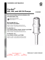
1
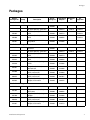
Installation and Operation
Fire-Ball®
225, 300, and 425 Oil Pumps
For non-corrosive and non-abrasive oils
and lubricants only.
Important Safety Instructions
Read all warnings and instructions in this manual.
Save these instructions.
Mini Fire-Ball 225, 3:1
Parts 246775 and 248097
540 psi (3.7 MPa, 37 bar) Maximum Working Pressure
180 psi (1.24 MPa, 12.4 bar) Maximum Air Input Pressure
Fire-Ball 300, 5:1
Parts 203876, 203872, 203857, 204254, and 222087
900 psi (6.2 MPa, 62 bar) Maximum Working Pressure
180 psi (1.24 MPa, 12.4 bar) Maximum Air Input Pressure
Fire-Ball 425, 10:1
Parts 205626, 222065, and 222095
1800 psi (12.4 MPa, 124 bar) Maximum Working Pressure
180 psi (1.24 MPa, 12.4 bar) Maximum Air Input Pressure
Mascott Equipment Co
Portland
Seattle
Pasco
(800)Graco
452-5019
(800)
(888)
450-7867
Inc. P.O. Box
1441481-7311
Minneapolis, MN
55440-1441
Copyright 2004, Graco Inc. is registered to I.S. EN ISO 9001
309868B
Contents
Contents
Contents . . . . . . . . . . . . . . . . . . . . . . . . . . . . . . . . . . 2
Packages . . . . . . . . . . . . . . . . . . . . . . . . . . . . . . . . . 3
Manual Conventions . . . . . . . . . . . . . . . . . . . . . . . . 4
Warning . . . . . . . . . . . . . . . . . . . . . . . . . . . . . . . . . . . 5
Installation . . . . . . . . . . . . . . . . . . . . . . . . . . . . . . . . 6
Mounting the Pump . . . . . . . . . . . . . . . . . . . . . . . 7
Grounding . . . . . . . . . . . . . . . . . . . . . . . . . . . . . . 7
Mobil Mounting . . . . . . . . . . . . . . . . . . . . . . . . . 13
Operation . . . . . . . . . . . . . . . . . . . . . . . . . . . . . . . . 15
Relieving Pressure . . . . . . . . . . . . . . . . . . . . . . 15
Starting and Adjusting the Pump . . . . . . . . . . . 15
Parts . . . . . . . . . . . . . . . . . . . . . . . . . . . . . . . . . . . . 16
Universal Pump Package
Fire-Ball 225 Model 248230
Fire-Ball 300 Model 225852
Fire-Ball 425 Model 225853 . . . . . . . . . . . . 16
16-gallon (60 Liter) Gear Lube Dispenser
Fire-Ball 225 Model 246903
Fire-Ball 300 Model 225728 . . . . . . . . . . . . 18
16-gallon (60 Liter) Drum Cover Pump
Fire-Ball 225 Model 246904
Fire-Ball 300 Model 225094 . . . . . . . . . . . . 20
55-gallon (208 Liter) Drum Cover Pump
Fire-Ball 225 Model 246906
Fire-Ball 300 Model 225642
Fire-Ball 425 Model 225782 . . . . . . . . . . . . 22
55-/275-gallon (208 Liter) Drum Bung-Mount Pump
Fire-Ball 225 Model 246907
Fire-Ball 300 Model 225640
Fire-Ball 300 Model 225931
Fire-Ball 425 Model 225786 . . . . . . . . . . . . 24
16-gallon (60 Liter) Drum Cover, Truck Mounted
Pump
Fire-Ball 300 Model 222086 . . . . . . . . . . . . 26
55-gallon (208 Liter) Drum Cover, Truck Mounted
Pump
Fire-Ball 300 Model 206655
Fire-Ball 425 Model 206656 . . . . . . . . . . . . 27
55-gallon (208 Liter) Bung Adapter, Truck Mounted
Pump
Fire-Ball 300 Model 204264
Fire-Ball 425 Model 222067 . . . . . . . . . . . . 28
Technical Data . . . . . . . . . . . . . . . . . . . . . . . . . . . . 30
Fire-Ball 225 (3:1) . . . . . . . . . . . . . . . . . . . . . . . 30
Fire-Ball 300 (5:1) . . . . . . . . . . . . . . . . . . . . . . . 30
Fire-Ball 425 (10:1) . . . . . . . . . . . . . . . . . . . . . . 30
Dimensions . . . . . . . . . . . . . . . . . . . . . . . . . . . . . . . 31
Fire-Ball 225 . . . . . . . . . . . . . . . . . . . . . . . . . . . 31
Fire-Ball 300 . . . . . . . . . . . . . . . . . . . . . . . . . . . 32
Fire-Ball 425 . . . . . . . . . . . . . . . . . . . . . . . . . . . 33
Graco Standard Warranty . . . . . . . . . . . . . . . . . . . 34
Graco Information . . . . . . . . . . . . . . . . . . . . . . . 34
Additional Reference Manuals
This manual covers the installation and operation of Graco Fire-Ball pumps. For information on service and repair of
these pumps, please see the following manual.
•
Fire-Ball Pump Service, Troubleshooting, and Repair 309869.
You should also read the instruction manuals for all components of your system.
2
Installation and Operation
Packages
Packages
Model/
Package No.
Pump
Description
Hose/
Fitting Kit
Cover/Bung
Adapter
Dispense
Kit
Air
Regulator
204574
237075
224512
Fire-Ball 225 Packages
248230
246775
Universal
246903
248097
16 gallon (60 liter), gear lube
248097
16 gallon (60 liter), drum
cover
222063
204574
224512
55 gallon (208 liter), drum
cover
222063
200326
224512
55/275 gallon (208/1041 liter),
bung mount
222063
222308
222062
246904
248097
246906
248097
246907
222062
Fire-Ball 300 Packages
225852
203876
Universal
225728
203872
16 gallon (60 liter), gear lube
203872
16 gallon (60 liter), drum
cover
222063
204574
55 gallon (208 liter), drum
cover
222063
200326
55 gallon (208 liter), bung
mount
222063
222308
275 gallon (1041 liter)
obround tank
222063
222308
16 gallon (60 liter), drum
cover, truck mount
222063
222060
55 gallon (208 liter) drum
cover, truck mount
222063
207367
55 gallon (208 liter) bung
adapter, truck mount
222063
204076
205626
Universal
222068
222065
55 gallon drum (208 liter),
drum cover
222066
200326
55 gallon (208 liter), bung
adapter
222066
222308
55 gallon (208 liter) drum
cover, truck mount
222066
207367
55 gallon (208 liter) bung
adapter, truck mount
222066
224579
225094
203857
225642
204254
225640
222087
225931
203872
222086
203857
206655
204254
204264
204574
237075
224512
Fire-Ball 425 Packages
225853
225782
222095
225786
222065
206656
222095
222067
Installation and Operation
3
Manual Conventions
Manual Conventions
Warning
Caution
WARNING
CAUTION
A caution alerts you to possible equipment damage or
destruction if you do not follow instructions.
A warning alerts you to possible serious injury or
death if you do not follow instructions.
Note
Symbols, such as fire and explosion (shown), alert you
to a specific hazard and direct you to read the indicated hazard warnings beginning on page 4.
A note indicates additional helpful information.
WARNINGS
EQUIPMENT MISUSE HAZARD
Misuse can cause death or serious injury.
•
Do not exceed the maximum working pressure or temperature rating of the lowest rated system
component. See Technical Data in all equipment manuals.
•
Use fluids and solvents that are compatible with equipment wetted parts. See Technical Data in
all equipment manuals. Read fluid and solvent manufacturer’s warnings.
•
Check equipment daily. Repair or replace worn or damaged parts immediately.
•
Do not alter or modify equipment.
•
Use equipment only for its intended purpose. Call your Graco distributor for information.
•
For professional use only.
•
Route hoses and cables away from traffic areas, sharp edges, moving parts, and hot surfaces.
•
Do not use hoses to pull equipment.
•
Comply with all applicable safety regulations.
PRESSURIZED EQUIPMENT HAZARD
Fluid from the gun/dispense valve, leaks, or ruptured components can splash in the eyes or on skin
and cause serious injury.
4
•
Follow Pressure Relief Procedure in this manual, when you stop spraying and before cleaning,
checking, or servicing equipment.
•
Tighten all fluid connections before operating the equipment.
•
Check hoses, tubes, and couplings daily. Replace worn or damaged parts immediately.
Installation and Operation
Warning
WARNING
SKIN INJECTION HAZARD
High-pressure fluid from gun, hose leaks, or ruptured components will pierce skin. This may look like just
a cut, but it is a serious injury that can result in amputation. Get immediate surgical treatment.
•
Do not point gun at anyone or at any part of the body.
•
Do not put your hand over the spray tip.
•
Do not stop or deflect leaks with your hand, body, glove, or rag.
•
Do not spray without tip guard and trigger guard installed.
•
Engage trigger lock when not spraying.
•
Follow Pressure Relief Procedure in this manual, when you stop spraying and before cleaning,
checking, or servicing equipment.
MOVING PARTS HAZARD
Moving parts can pinch or amputate fingers and other body parts.
•
Keep clear of moving parts.
•
Do not operate equipment with protective guards or covers removed.
•
Pressurized equipment can start without warning. Before checking, moving, or servicing equipment,
follow the Pressure Relief Procedure in this manual. Disconnect power or air supply.
TOXIC FLUID OR FUMES HAZARD
Toxic fluids or fumes can cause serious injury or death if splashed in the eyes or on skin, inhaled, or
swallowed.
•
Read MSDS’s to know the specific hazards of the fluids you are using.
•
Store hazardous fluid in approved containers, and dispose of it according to applicable guidelines.
FIRE AND EXPLOSION HAZARD
Flammable fumes, such as solvent and paint fumes, in work area can ignite or explode. To help prevent
fire and explosion:
•
Use equipment only in well ventilated area.
•
Eliminate all ignition sources; such as pilot lights, cigarettes, portable electric lamps, and plastic drop
cloths (potential static arc).
•
Keep work area free of debris, including solvent, rags and gasoline.
•
Do not plug or unplug power cords or turn lights on or off when flammable fumes are present.
•
Ground equipment and conductive objects. See Grounding instructions.
•
Use only grounded hoses.
•
Hold gun firmly to side of grounded pail when triggering into pail.
•
If there is static sparking or you feel a shock, stop operation immediately. Do not use equipment
until you identify and correct the problem.
Installation and Operation
5
Installation
Installation
The typical stationary installation shown in is only a
guide for selecting and installing a pump; it is not an
actual system design. Contact your Graco distributor for
assistance in designing a system to meet your needs.
Letters used to identify components in FIG. 1 are
referred to in the package installation drawings,
FIG. 3 through FIG. 7. Additional letter references
are used in installation drawings as necessary.
.
F
E
A
C
L
D
J
H
N
M
B
K
G
P
Key
A Bleed-type master air valve
B Air line filter
C Air regulator and gauge
D Air inlet
E Ground wire
F Pump
G Drain valve
H
J
K
L
M
N
P
Dispensing valve
Fluid hose
Thermal relief kit (235998)
Air line lubricator
Bung adapter
Fluid outlet
Extension tube
FIG. 1
6
Installation and Operation
Installation
Mounting the Pump
WARNING
Mount the pump securely so that it cannot move during operation. Failure to do so could result in personal
injury or equipment damage.
•
•
Select a location that allows the operator easy
access to the pump and air controls, sufficient room
to change supply containers, and a secure mounting platform.
If you are mounting the pump directly on the supply
container, be sure it is positioned so the pump’s
intake tube is no more than 1 in. (25 mm) from the
bottom of the container. Mount the pump to the
cover or other suitable mounting device.
•
To maintain grounding continuity when flushing or
relieving pressure, always hold a metal part of the
dispensing valve firmly to the side of a metal pail
and then open the dispensing valve.
To maintain grounding continuity when flushing or relieving pressure, always hold a metal part of the valve firmly
to the side of a grounded metal pail, then trigger the
valve.
To ground the pump, remove the ground screw (Z) and
insert through the eye of the ring terminal at end of
ground wire, (Y). Fasten the ground screw back onto the
pump and tighten securely. Connect the other end of the
ground wire to a true earth ground. See FIG. 2. To order
a ground wire and clamp order Part No. 222011.
To prevent damage to the pump, remove sediment from the bottom of the container before
installing a pump in an existing container.
Y
Z
Grounding
Proper grounding is essential to maintaining a safe system.
To reduce the risk of static sparking, ground the pump.
Check local electrical codes for detailed grounding
instructions for your area and equipment type. Be sure
the following equipment is properly grounded:
•
Pump: See FIG. 2
•
Air and Fluid hoses: Use only electrically conductive
hoses.
•
Air compressor: Follow manufacturer’s recommendations.
•
Dispensing valve: Obtain grounding through connection to a properly grounded fluid hose and pump.
•
Fluid supply container: Follow your local code.
•
Object being lubricated: Follow your local code.
•
Any pails used when flushing: Use only metal,
grounded pails when flushing. Make firm
metal-to-metal contact between a metal part of the
dispensing valve and the pail. Use the lowest possible pressure.
Installation and Operation
TI1052
FIG. 2
7
Installation
Universal Pump
Fire-Ball 225 Model 248230
Fire-Ball 300 Model 225852
Fire-Ball 425 Model 225853
1. Apply thread sealant to the male threads of the 3/8
npt swivel union (2d). Screw the union into the pump
air inlet (D).
2. Apply thread sealant to the male threads of the 1/2
npt swivel union (2b). Screw the union into the pump
fluid outlet (N).
3. Connect the 1/2 npt(mbe) fluid hose (2a) to the
swivel union (2b).
4. Connect the 3/8 npt(mbe) air hose (2c) to the swivel
union (2d).
F
D
2d
N
2b
2a
2c
FIG. 3
8
Installation and Operation
Installation
16-Gallon (60 Liter) Gear Lube Dispenser
Fire-Ball 225 Model 246903
Fire-Ball 300 Model 225728
drum. When installed, the bottom of the angle
should be about 1” (25 mm) from the bottom of the
drum. The down tube for 225728 is sized for the
container.
1. Assemble the base (5) as shown in FIG. 4. Place an
opened 16-gallon (60 liter) drum on the base and
secure it with the hold-down clamps. Tighten the
hold-down clamp bolts
3. Set the cover (4) on the drum and secure the
thumbscrews (Q). Install the pump (F) on the cover
(4) with the screws (R), washers and nuts (S) provided
2. For 246903, cut the extension tube (P) at a 45°
angle to a length appropriate for the size of the
4. Connect the hose (2a) to the pump fluid outlet (N).
F
2a
3b
D
3d
3d
R
N
2b
3a
4
3c
S
Q
P
5
FIG. 4
Installation and Operation
9
Installation
16-Gallon (60 Liter) Drum Cover Pump
Fire-Ball 225 Model 246904
Fire-Ball 300 Model 225094
4. Assemble the air regulator kit (items 3a-3d) to the
pump air inlet (D) as shown. Use thread sealant and
tighten all parts securely.
1. Set the cover (4) on a 16-gallon (60 liter) drum and
secure with the thumbscrews (Q). See FIG. 5.
5. Apply thread sealant to the male threads of the 3/8
npt swivel union (2d). Screw the union into the
bleed-type master air valve (3c).
2. For 246904 cut the extension tube (P) at a 45° angle
to a length appropriate for the size of the drum.
When installed, the bottom of the angle should be
about 1” (25 mm) from the bottom of the drum. The
down tube for 225094 is sized for the container.
6. Apply thread sealant to the male threads of the 1/2
npt swivel union (2b). Screw the union into the pump
fluid outlet (N).
3. Install the pump (F) on the cover (4) with the screws
(R), washers and nuts (S) supplied.
7. Connect the 1/2 npt(mbe) fluid hose (2a) to the
swivel union (2b).
8. Connect the 3/8 npt(mbe) air hose (2c) to the swivel
union (2d).
F
3d
3b
R
D
N
2b
A
3d
3c
2a
2d
3a
P
2c
S
4
Q
FIG. 5
10
Installation and Operation
Installation
55-Gallon (208 Liter) Drum Cover Pump
Fire-Ball 225 Model 246906
Fire-Ball 300 Model 225642
Fire-Ball 425 Model 225782
1. For 246906 cut the extension tube (P) at a 45° angle
to a length appropriate for the size of the drum.
When installed, the bottom of the angle should be
about 1” (25 mm) from the bottom of the drum. For
225642 and 225782 the down tube is sized for the
container.
2. Set the cover (4) on a 55-gallon (208 liter) drum.
Install the pump (F) on the cover with the screws (R)
supplied. See FIG. 6
3. Assemble the air regulator kit (items 3a-3d) to the
pump air inlet (D) as shown. Use thread sealant and
tighten all parts securely.
4. Apply thread sealant to the male threads of the 3/8
npt swivel union (2d). Screw the union into the
bleed-type master air valve (3c).
5. Apply thread sealant to the male threads of the 1/2
npt swivel union (2b). Screw the union into the pump
fluid outlet (N).
6. Connect the 1/2 npt(mbe) fluid hose (2a) to the
swivel union (2b).
7. Connect the 3/8 npt(mbe) air hose (2c) to the swivel
union (2d).
F
3d
3b
D
R
N
2b
3d
3c
2a
2d
3a
2c
4
P
FIG. 6
Installation and Operation
11
Installation
55-/275-Gallon (208 Liter) Drum,
Bung-Mount Pump
Fire-Ball 225 Model 246907
Fire-Ball 300 Models 225640 and 225931
3. Tighten the bung adapter screw (T) to hold the
pump in position.
4. Apply thread sealant to the male threads of the 3/8
npt swivel union (2d). Screw the union into the pump
air inlet (D).
1. Screw the bung adapter (M) into the bung hole of
the drum. See FIG. 7.
5. Apply thread sealant to the male threads of the 1/2
npt swivel union (2b). Screw the union into the pump
fluid outlet (N).
2. For 246907 cut the extension tube (P) at a 45° angle
to a length appropriate for the size of the drum.
When installed, the bottom of the angle should be
about 1” (25 mm) from the bottom of the drum. For
224640 and 225931 the down tube is sized for the
container.
6. Connect the 1/2 npt(mbe) fluid hose (2a) to the
swivel union (2b).
7. Connect the 3/8 npt(mbe) air hose (2c) to the swivel
union (2d).
F
N
D
2b
2d
2a
2c
M
T
P
Model 225931
FIG. 7
12
Installation and Operation
Installation
Mobil Mounting
Closed Bung-Type-Drum, Cover-Mounted
Pump
Mobil Mounting Layout
1. Insert the pump extension tube through the gasket
(Z) and drum cover (AA). Fasten the Fire-Ball 300
from the top and the Fire-Ball 425 from the bottom.
See FIG. 9.
Plan the layout for easy operator access to the pump air
controls, sufficient space to change drums, and a
secure mounting platform.
Drum Mounting
1. Place the drum in the desired location.
2. Place the hold-down lugs (Y) or drum locators (X)
around the drum base and bolt directly to the truck
bet or mounting platform. See FIG. 8.
3. Guide the pump extension tube through the drum
bung hole (CC) and place the cover on the drum.
See FIG. 9.
4. Align the drum cover eyelets (T) with the hold-down
rods (W), install the hold-down brackets (V) and
wing nuts (U) and tighten securely. See FIG. 8.
U
T
2. Slide the rubber grommet (BB), tapered end down,
onto the extension tube and push it up against the
pump base. See FIG. 9.
V
W
Z
AA
BB
CC
X
Gasket
Drum cover
Grommet
Bung Hole
Z
AA
BB
T
U
V
W
X
Y
Drum cover eyelets
Wing nuts
Hold-down brackets
Hold-down rods
Drum locators
Hold-down rod lugs
Y
CC
FIG. 8
Open Drum, Cover-Mounted Pumps
FIG. 9
1. Remove the original drum cover.
2. Mount the new drum cover and fasten in place.
3. Guide the pump extension tube through the mounting gasket.
4. Align the drum cover eyelets (T) with the hold-down
rods (W), install the cover brackets (V) and wing
nuts (U) and tighten securely. See FIG. 8.
Installation and Operation
13
Installation
Closed Bung-Type-Drum,
Sturdi-Clamp-Mounted Pumps
1. Remove the adjustable bung adapter fro the pump
extension tube.
DD
EE
2. Screw the bung adapter (HH) into the bung hole.
3. Loosen the wing nuts (EE) and slide the clamp (DD)
onto the pump extension tube, up to the base. See
FIG. 10.
FF
4. Holding the clamp onto the pump, insert the pump
extension tube through the bung adapter, and lower
the pump until the clamp rests on the edge of the
drum. See FIG. 10.
GG
5. Install the sturdi-clamp so its upper jaw fits against
the pump base projection, its u-bolt (GG) fits around
the extension tube, and its lower jaw fits against the
bung adapter. Tighten the wing nuts (EE). See FIG.
10.
6. Tighten the T-handle (FF) firmly to the side of the
drum.
14
HH
DD Clamp
EE Wing Nuts
FF T-handle
GG U-bolt
HH Bung adapter
FIG. 10
Installation and Operation
Operation
Operation
See FIG. 1 to identify references shown in parentheses,
i.e.,(A).
3. Open the pump air regulator (C) slowly, just until the
pump is running. When the pump is primed and all
air has been pushed out of the lines, close the dispensing valve (H).
WARNING
This equipment stays pressurized until pressure is
manually relieved. Read PRESURIZED EQUIPMENT
HAZARD warnings on page 4.
Maximum working pressure of all components in the
system may not be the same. To reduce risk of overpressurizing any component, be sure you know the
maximum working pressure of each component.
Never exceed the maximum working pressure of the
lowest rated component in the system. Overpressurizing any component can result in rupture, fire, explosion, property damage, and serious injury.
To determine the fluid output pressure using the air
regulator reading, multiply the ratio of the pump by the
air pressure shown on the regulator gauge. For example:
3 (:1) ratio x 100 psi air = 300 psi fluid output
Limit the air pressure to the pump so that no air line or
fluid line component is overpressurized.
Relieving Pressure
1. Close the pump air regulator (C) and the bleed-type
master air valves (A) (required in your system).
2. Hold a metal part of the dispensing valve (H) firmly
to a grounded metal waste container, and trigger the
valve to relieve the fluid pressure.
NOTE: When the pump is primed, and with sufficient air
supplied, the pump starts when the dispensing valve (H)
is opened, and shuts off when it is closed.
4. Adjust the air regulator (C) until you get sufficient
flow from dispensing valve (H). Always run the
pump at the lowest pressure necessary to get the
desired results. Do not exceed the maximum working pressure of any component in the system.
CAUTION
Never allow the pump to run dry of the fluid being
pumped. A dry pump will quickly accelerate to a high
speed, possibly causing pump damage. It may also get
very hot.
5. If your pump accelerates quickly or is running too
fast, stop it immediately and check the fluid supply. If
the supply container is empty and air has been
pumped into the lines, prime the pump and lines
with fluid, or flush it and leave it filled with a compatible solvent. Be sure to eliminate all air from the fluid
lines.
6. Read and follow the instructions supplied with each
component in your system.
7. If the pump will be unattended for any period of
time, if there is an air supply interruption, or at the
end of the work shift, shut off the system and always
relieve the pressure.
Starting and Adjusting the Pump
WARNING
Read the MOVING PARTS HAZARD and TOXIC
FLUID OR FUMES warnings on page 5
1. With the air regulator (C) closed, open the
bleed-type master air valve (A).
2. Open the dispensing valve (H) into a grounded
metal waste container, making firm metal-to-metal
contact between the container and valve.
Installation and Operation
15
Parts
Parts
Universal Pump Package
Fire-Ball 225 Model 248230
Fire-Ball 300 Model 225852
Fire-Ball 425 Model 225853
1
2d
2b
2a
2c
16
Installation and Operation
Parts
Parts List
Ref.
No.
1
2
Part No. Description
Qty.
246775 PUMP, Mini-Fire-Ball 225 3:1,
1
universal; (for 248230, see 309869
for parts)
203876 Pump, Fire-Ball 300 5:1,
1
universal; (for 225852, see 309869
for parts)
205626 Pump, Fire-Ball 425 10:1,
1
universal; (for 225853, see 309869
for parts
222062 HOSE AND FITTING KIT;
1
(for 248230 and 225852) Includes
items 2a-2d
222068 HOSE AND FITTING KIT;
1
(for 225853) Includes items 2a-2d
Installation and Operation
Ref.
No.
2a
2b
2c
2d
Part No. Description
Qty.
220598 •FLUID HOSE,1/2’ ID, cpld
1
1/2-14 npt(m), 18 in. (457 mm) (for
222062)
109108 •FLUID HOSE, (for 222068)
1
155470 •UNION, swivel, 90°; 1/2 npt(m) x
1
1/2 npsm(f) (for 222062)
160327 •UNION, 90°, 3/4-14 (for 222068)
1
204560 •AIR HOSE, 3/8 in. ID, cpld
1
3/8-18 npt(m), 18 in. (457 mm)
(for 222062)
218093 •AIR HOSE, (for 222068)
1
155494 •UNION, swivel, 90°; 3/8 npt(m) x
1
3/8 npsm(f) (for 222062)
155470 •UNION, swivel, 90°; 1/2 npt(m) x
1
1/2 npsm(f) (for 222068)
17
Parts
16-gallon (60 Liter) Gear Lube Dispenser
Fire-Ball 225 Model 246903
Fire-Ball 300 Model 225728
1
3b
2a
3d
3d
2b
3a
3c
4
5
18
Installation and Operation
Parts
Parts List
Ref.
No. Part No. Description
1
2
2a
2b
3
3a
3b
3c
3d
4
5
Qty.
248097 PUMP, Mini-Fire-Ball 225 3:1,
multi-length; (for 246903, see
309869 for parts)
203872 PUMP, Fire-Ball 300 5:1; (for
225728, see 309869 for parts)
237075 DISPENSE KIT;
Included items 2a and 2b
See manual 307884
220591 • HOSE, coupled, 6 ft.
1
238463 • VALVE, dispense
224512 AIR REGULATOR KIT
Includes items 3a-3d
110234 • REGULATOR, air; 3/8 npt(f)
0-250 psi
0-1.7 MPa, 0-14.4 bar) range
See manual 308167
100960 • GAUGE, air pressure
110224 • VALVE, air, bleed-type; 3/8 npt(f)
156849 • NIPPLE, 3/8 npt
204574 COVER, drum;
See manual 306345 for parts
203622 PORTABLE BASE;
See manual 308668 for parts
1
1
(1/2 in. npt (mbe)
Installation and Operation
1
1
1
1
1
2
1
1
19
Parts
16-gallon (60 Liter) Drum Cover Pump
Fire-Ball 225 Model 246904
Fire-Ball 300 Model 225094
1
3d
3b
2b
3d
3c
2a
2d
3a
2c
4
20
Installation and Operation
Parts
Parts List
Ref.
No. Part No. Description
1
2
2a
248097 PUMP, Mini-Fire-Ball 225 3:1,
multi-length; (for 246904, see
309869 for parts)
203872 PUMP, Fire-Ball 300 5:1; (for
225094, see 309869 for parts)
222063 HOSE AND FITTING KIT
Includes items 2a-2d
220591 • HOSE, fluid; nitrile; 1/2 in. ID;
Qty.
1
1
1
1
2b
1/2 npt(mbe); 6 ft (1.83 m)
155470 • UNION, swivel, 90°; 1/2 npt(m) x
1/2 npsm(f)1
2c
203320 • HOSE, air; buna–N; 3/8 in. ID;
2d
155494 • UNION, swivel, 90°; 3/8 npt(m) x
1
3
224512 AIR REGULATOR KIT
Includes items 3a-3d
110234 • REGULATOR, air; 3/8 npt(f)
0-250 psi
0-1.7 MPa, 0-14.4 bar) range
See manual 308167
100960 • GAUGE, air pressure
110224 • VALVE, air, bleed-type; 3/8 npt(f)
156849 • NIPPLE, 3/8 npt
204574 COVER, drum;
See 306345 for parts
1
1
1
3/8 npt(mbe); 6 ft (1.83 m)
3a
3b
3c
3d
4
3/8 npsm)
Installation and Operation
1
1
1
2
1
21
Parts
55-gallon (208 Liter) Drum Cover Pump
Fire-Ball 225 Model 246906
Fire-Ball 300 Model 225642
Fire-Ball 425 Model 225782
1
3d
3b
2b
3d
3c
2a
2d
3a
2c
4
22
Installation and Operation
Parts
Ref.
No. Part No. Description
1
2
2a
248097 PUMP, Mini-Fire-Ball 225 3:1,
multi-length; (for 246906, see
309869 for parts)
203857 PUMP, Fire-Ball 300 5:1; (for
225642, see 309869 for parts)
222065 PUMP, Fire-Ball 425 10:1; (for
225782, see 309869 for parts)
222063 HOSE AND FITTING KIT
(for 246906 and 225642)
Includes items 2a-2d
222066 HOSE AND FITTING KIT
(for 225782) Includes items 2a-2d
220591 • HOSE, fluid; nitrile; 1/2 in. ID;
1/2 npt(mbe); 6 ft (1.83 m)
Qty.
1
1
1
1
(for 222063)
109105 • HOSE, fluid; nitrile; 3/4 in. ID;
3/4 npt(mbe); 6 ft (1.83 m)
1
(for 222066)
2b
2c
155470 • UNION, swivel, 90°; 1/2 npt(m) x
1/2 npsm(f) (for 222063)
•
UNION, swivel, 90°; 3/4 npt(m) x
160327
3/4 npsm(f) (for 222066)
203320 • HOSE, air; buna–N; 3/8 in. ID;
1
1
3/8 npt(mbe); 6 ft (1.83 m)
(for 222063)
205418 • HOSE, air; buna–N; 1/2 in. ID;
1
1/2 npt(mbe); 6 ft (1.83 m)
(for 222066)
2d
3
3a
3b
3c
3d
4
155494 • UNION, swivel, 90°; 3/8 npt(m) x
3/8 npsm)
(for 222063)
155470 • UNION, swivel, 90°; 1/2-14 npt(m) x
1/2 npsm(f) (for 222066)
224512 AIR REGULATOR KIT
(for 246906 and 225642 only)
Includes items 3a-3d
110234 • REGULATOR, air; 3/8 npt(f)
0-250 psi
0-1.7 MPa, 0-14.4 bar) range
See manual 308167
100960 • GAUGE, air pressure
110224 • VALVE, air, bleed-type; 3/8 npt(f)
156849 • NIPPLE, 3/8 npt
200326 COVER, drum;
See 306345 for parts
Installation and Operation
1
1
1
1
1
1
1
1
23
Parts
55-/275-gallon (208 Liter) Drum Bung-Mount Pump
Fire-Ball 225 Model 246907
Fire-Ball 300 Model 225640
Fire-Ball 300 Model 225931
Fire-Ball 425 Model 225786
1
2b
2d
2a
2c
24
Installation and Operation
Parts
Parts List
Ref.
No. Part No. Description
1
2
2a
248097 PUMP, Mini-Fire-Ball 225 3:1, multilength; (for 246907, see 309869 for
parts)
204254 PUMP, Fire-Ball 300 5:1; (for
225640, see 309869 for parts)
222087 PUMP, Fire-Ball 300 5:1; (for
225931, see 309869 for parts)
222095 PUMP, Fire-Ball 425 10:1; (for
225786, see 309869 for parts)
222063 HOSE AND FITTING KIT
(for 246907, 225640 and 225931)
Includes items 2a-2d
222066 HOSE AND FITTING KIT
(for 225786) Includes items 2a-2d
220591 • HOSE, fluid; nitrile; 1/2 in. ID;
1/2 npt(mbe); 6 ft (1.83 m)
Qty.
1
1
1
1
(for 222063)
109105 • HOSE, fluid; nitrile; 3/4 in. ID;
3/4 npt(mbe); 6 ft (1.83 m)
1
(for 222066)
2b
2c
155470 • UNION, swivel, 90°; 1/2 npt(m) x
1/2 npsm(f) (for 222063)
160327 • UNION, swivel, 90°; 3/4 npt(m) x
3/4 npsm(f) (for 222066)
203320 • HOSE, air; buna–N; 3/8 in. ID;
1
1
3/8 npt(mbe); 6 ft (1.83 m)
(for 222063)
205418 • HOSE, air; buna–N; 1/2 in. ID;
1
1/2 npt(mbe); 6 ft (1.83 m)
(for 222066)
2d
155494 • UNION, swivel, 90°; 3/8 npt(m) x
1
(for 222063)
155470 • UNION, swivel, 90°; 1/2-14 npt(m) x
1/2 npsm(f) (for 222066)
1
3/8 npsm)
Installation and Operation
25
Parts
16-gallon (60 Liter) Drum Cover, Truck Mounted Pump
Fire-Ball 300 Model 222086
2c
2d
4
2a
3
2b
Parts List
Ref.
No. Part No. Description
Ref.
No. Part No. Description
1
2
2a
26
203872 PUMP, Fire-Ball 300 5:1;
(See 309869 for parts)
222063 HOSE AND FITTING KIT
Includes items 2a-2d
220591 • HOSE, fluid; nitrile; 1/2 in. ID;
1/2 npt(mbe); 6 ft (1.83 m)
Qty.
Qty.
2b
155470 • UNION, swivel, 90°; 1/2 npt(m) x
1
2c
203320 • HOSE, air; buna–N; 3/8 in. ID;
1
1
2d
155494 • UNION, swivel, 90°; 3/8 npt(m) x
1
1
3
4
222060 DRUM COVER
222061 HOLD-DOWN KIT
See manual 306345 for parts
1
1
1
1/2 npsm(f)1
3/8 npt(mbe); 6 ft (1.83 m)
3/8 npsm)
Installation and Operation
Parts
55-gallon (208 Liter) Drum Cover, Truck Mounted Pump
Fire-Ball 300 Model 206655
Fire-Ball 425 Model 206656
2c
2d
4
2a
2b
3
Parts List
Ref.
No. Part No. Description
Ref.
No. Part No. Description
1
2
2a
203857 PUMP, Fire-Ball 300 5:1; (for
206655, see 309869 for parts)
222065 PUMP, Fire-Ball 425 10:1; (for
206656, see 309869 for parts)
222063 HOSE AND FITTING KIT
Includes items 2a-2d
220591 • HOSE, fluid; nitrile; 1/2 in. ID;
1/2 npt(mbe); 6 ft (1.83 m)
Installation and Operation
Qty.
Qty.
2b
155470 • UNION, swivel, 90°; 1/2 npt(m) x
1
2c
203320 • HOSE, air; buna–N; 3/8 in. ID;
1
2d
155494 • UNION, swivel, 90°; 3/8 npt(m) x
1/2 npsm(f)1
3/8 npt(mbe); 6 ft (1.83 m)
1
1
3
4
3/8 npsm)
DRUM
COVER
207367
207361 HOLD-DOWN KIT
See manual 306345 for parts
1
1
1
27
Parts
55-gallon (208 Liter) Bung Adapter, Truck Mounted Pump
Fire-Ball 300 Model 204264
Fire-Ball 425 Model 222067
2c
1
2d
2a
4
2b
5
3
28
Installation and Operation
Parts
Parts List
Ref.
No. Part No. Description
1
2
2a
204254 PUMP, Fire-Ball 300 5:1;
(For 204264, see 309869 for parts)
222095 PUMP, Fire-Ball 425 10:1;
(For 222067, see 309869 for parts)
222063 HOSE AND FITTING KIT
(for 204264) Includes items 2a-2d
222066 HOSE AND FITTING KIT
(for 222067) Includes items 2a-2d
220591 • HOSE, fluid; nitrile; 1/2 in. ID;
1/2 npt(mbe); 6 ft (1.83 m)
Qty.
1
1
1
1
(for 222063)
109105 • HOSE, fluid; nitrile; 3/4 in. ID;
3/4 npt(mbe); 6 ft (1.83 m)
1
(for 222066)
2b
2c
155470 • UNION, swivel, 90°; 1/2 npt(m) x
1/2 npsm(f) (for 222063)
•
UNION, swivel, 90°; 3/4 npt(m) x
160327
3/4 npsm(f) (for 222066)
203320 • HOSE, air; buna–N; 3/8 in. ID;
1
1
3/8 npt(mbe); 6 ft (1.83 m)
(for 222063)
205418 • HOSE, air; buna–N; 1/2 in. ID;
1
1/2 npt(mbe); 6 ft (1.83 m)
(for 222066)
2d
3
4
5
155494 • UNION, swivel, 90°; 3/8 npt(m) x
3/8 npsm)
(for 222063)
155470 • UNION, swivel, 90°; 1/2-14 npt(m) x
1/2 npsm(f) (for 222066)
204076 BUNG ADAPTER, sealed
(for 204264)
224579 BUNG ADAPTER, sealed
(for222067)
207361 HOLD-DOWN KIT
See manual 306345 for parts
204095 STURDI-CLAMP
Installation and Operation
1
1
1
1
1
29
Technical Data
Technical Data
Fire-Ball 225 (3:1)
Fluid to air ratio......................................................... 3:1
Cycles/gallon (cycles/liter) ............................ 43.5 (11.4)
Fluid flow @80 cpm (gpm/lpm)....................... 1.84 (7.0)
Pumping distance guideline.......... up to 250 ft. (76.2 m)
Maximum fluid pressure ........ 540 psi (3.7 MPa, 37 bar)
Wetted materials ........... steel, polyurethane, aluminum,
........................................................................... buna-N
Air inlet port size ......................................... 3/8 in. npt(f)
Fluid inlet port size ...................................... 1.5 in. npt(f)
Fluid outlet port size.................................... 1/2 in. npt(f)
Sound pressure (measured 1 meter from unit) ...77.8dB
Sound pressure (ISO 9614-2).............................85.6dB
Air motor effective diameter.............. 2.25 in. (57.2 mm)
Air operating range ............... 40-180 psi (0.28-1.2 MPa,
...................................................................... 2.8-12 bar)
Approx. air consumption and fluid flow @100 psi air and
80 cpm..... 8.5 scfm @2.1 gpm (.241 m3/min @7.9 lpm)
Fire-Ball 425 (10:1)
Fluid to air ratio .......................................................10:1
Cycles/gallon (cycles/liter) ..............................19.6 (5.2)
Dry suction lift (feet of water)......................................23
Fluid flow @80 cpm (gpm/lpm) .......................4.1 (15.4)
Wetted materials............steel, polyurethane, aluminum,
...............................................................buna-N, Rulon®
Pumping distance guideline ........up to 750 ft. (228.6 m)
Air inlet port size ......................................... 3/8 in. npt(f)
Air motor effective diameter ............ 4.25 in. (107.9 mm)
Fluid inlet port size ..................................... 1.5 in. npt(f)
Air operating range ...............40-180 psi (0.28-1.2 MPa,
......................................................................2.8-12 bar)
Fluid outlet port size ................................... 1/2 in. npt(f)
Sound pressure (measured 1 meter from unit)... 77.8dB
Maximum fluid pressure...1800 psi (12.4 MPa, 124 bar)
Approx. air consumption and fluid flow @100 psi air and
80 cpm .32.0 scfm @4.1 gpm (.555 m3/min @15.4 lpm)
Sound pressure (ISO 9614-2) ............................ 85.6dB
Dry suction lift (feet of water) ..................................... 26
Fire-Ball 300 (5:1)
Fluid to air ratio......................................................... 5:1
Cycles/gallon (cycles/liter) .............................. 28.4 (8.6)
Fluid flow @80 cpm (gpm/lpm)......................... 2.8 (9.3)
Pumping distance guideline........ up to 500 ft. (152.5 m)
Maximum fluid pressure ........ 900 psi (6.2 MPa, 62 bar)
Wetted materials ..steel, polyurethane, aluminum, nitrile
Air inlet port size ......................................... 1/2 in. npt(f)
Fluid inlet port size ...................................... 1.5 in. npt(f)
Fluid outlet port size.................................... 3/4 in. npt(f)
Sound pressure (measured 1 meter from unit) .80.85dB
Sound pressure (ISO 9614-2)...........................94.62dB
Air motor effective diameter................ 3.0 in. (76.2 mm)
Air operating range ............... 40-180 psi (0.28-1.2 MPa,
...................................................................... 2.8-12 bar)
Approx. air consumption and fluid flow @100 psi air and
80 cpm..... 8.5 scfm @2.1 gpm (.241 m3/min @7.9 lpm)
Dry suction lift (feet of water)......................................26
30
Installation and Operation
Dimensions
Dimensions
Fire-Ball 225
Model 246775
Universal
Model 246775
Universal
Overall Length: 18.9 in. (48 cm)
3/8 in. npt(f)
air inlet
Grounding
screw
Model 248097
Variable length
Overall Length: 59.2 in. (150.4 cm)
Model 248097
Variable length
8.9 in.
(20 cm)
1/2 in. npt(f)
fluid outlet
3/8 in. npt(f)
air inlet
1-1/2 in. npt
grounding
screw
05752
1/2 in. npt(f)
fluid outlet
Mounting Hole Layout
8.9 in.
(20 cm)
4.250 in. (10.8 cm) bolt circle
0.281 in. (7.1 mm) diameter clearance holes
Installation and Operation
40.68 in. (103.33
cm) drop tube is
cut to length
31
Dimensions
Fire-Ball 300
Model 203857
55-gal. (400 lb) drum size, cover mount
Overall Length: 45.6 in. (115.8 cm)
Model 203876
Universal
Model 203872
16-gal. (120 lb) drum size, cover mount
Overall Length: 38.1 in. (96.8 cm)
Model 204254
55-gal. (400 lb) drum size, bung mount
Overall Length: 49.9 in. (126.7 cm)
3/8 in. npt(f)
air inlet
grounding
screw
Model 222087
275-gal. tank size, bung mount
Overall Length: 59.9 in. (152.1 cm)
1/2 in. npt(f)
fluid outlet
8.9 in.
(22.6 cm)
05750
Overall Length: 20.7 in (52.6 cm)
3/8 in. npt(f)
air inlet
grounding
screw
Mounting Hole Layout
Model 203857
33.8 in. (85.9 cm)
Gasket
Part No. 161023
Model 203872
26.3in. 66.9 cm)
Model 204254
38.1in. (96.8 cm)
Two 0.265-in. (.673 cm)
diameter holes on 5-in.
(12.7 cm) bolt circle
Four 0.265-in. (.673 cm)
diameter holes on 5-in.
(12.7 cm) bolt circle
2-Hole
Mounting Pattern
32
3-in. (7.62 cm)
diameter hole
1/2 in. npt(f)
fluid outlet
Model 222087
48.1 in. (122.2 cm)
04127
05754
4-Hole
Mounting Pattern
Installation and Operation
Dimensions
Fire-Ball 425
Model 205626
Universal
1/2 in. npt
air inlet
18.4in.
(46.7 cm)
3/4 in. npt
fluid outlet
3/4 in npt
muffler port
Model
205626
25.8 in.
(65.5 cm)
7.4 in.
(18.8 cm)
Note: For
sealed tank
mounting use
gasket 192658.
Model 222065
32.3 in. (82 cm)
Mounting Hole Layout
06035
Model 222095
36.6 in. (92.9 cm)
2.25-in. (5.7 cm)
diameter clearance hole
45°
45_
Four 0.406-in.
(1.03 cm)
diameter holes
on 7-in. (17.8
cm) bolt circle
Four threaded
holes on bottom
of air motor base
are 1/4-20 UNC
on 4.25-in. (10.8
cm) bolt circle.
8.0-in. (20.3 cm)
diameter of flange
Installation and Operation
33
Graco Standard Warranty
Graco warrants all equipment referenced in this document which is manufactured by Graco and bearing its name to be free from defects in material
and workmanship on the date of sale to the original purchaser. With the exception of any special, extended, or limited warranty published by Graco,
Graco will, for a period of twelve months from the date of sale, repair or replace any part of the equipment determined by Graco to be defective.
This warranty applies only when the equipment is installed, operated and maintained in accordance with Graco’s written recommendations.
This warranty does not cover, and Graco shall not be liable for general wear and tear, or any malfunction, damage or wear caused by faulty
installation, misapplication, abrasion, corrosion, inadequate or improper maintenance, negligence, accident, tampering, or substitution of
non-Graco component parts. Nor shall Graco be liable for malfunction, damage or wear caused by the incompatibility of Graco equipment with
structures, accessories, equipment or materials not supplied by Graco, or the improper design, manufacture, installation, operation or maintenance
of structures, accessories, equipment or materials not supplied by Graco.
This warranty is conditioned upon the prepaid return of the equipment claimed to be defective to an authorized Graco distributor for verification of
the claimed defect. If the claimed defect is verified, Graco will repair or replace free of charge any defective parts. The equipment will be returned
to the original purchaser transportation prepaid. If inspection of the equipment does not disclose any defect in material or workmanship, repairs will
be made at a reasonable charge, which charges may include the costs of parts, labor, and transportation.
THIS WARRANTY IS EXCLUSIVE, AND IS IN LIEU OF ANY OTHER WARRANTIES, EXPRESS OR IMPLIED, INCLUDING BUT NOT LIMITED
TO WARRANTY OF MERCHANTABILITY OR WARRANTY OF FITNESS FOR A PARTICULAR PURPOSE.
Graco’s sole obligation and buyer’s sole remedy for any breach of warranty shall be as set forth above. The buyer agrees that no other remedy
(including, but not limited to, incidental or consequential damages for lost profits, lost sales, injury to person or property, or any other incidental or
consequential loss) shall be available. Any action for breach of warranty must be brought within two (2) years of the date of sale.
GRACO MAKES NO WARRANTY, AND DISCLAIMS ALL IMPLIED WARRANTIES OF MERCHANTABILITY AND FITNESS FOR A
PARTICULAR PURPOSE, IN CONNECTION WITH ACCESSORIES, EQUIPMENT, MATERIALS OR COMPONENTS SOLD BUT NOT
MANUFACTURED BY GRACO. These items sold, but not manufactured by Graco (such as electric motors, switches, hose, etc.), are subject to
the warranty, if any, of their manufacturer. Graco will provide purchaser with reasonable assistance in making any claim for breach of these
warranties.
In no event will Graco be liable for indirect, incidental, special or consequential damages resulting from Graco supplying equipment hereunder, or
the furnishing, performance, or use of any products or other goods sold hereto, whether due to a breach of contract, breach of warranty, the
negligence of Graco, or otherwise.
FOR GRACO CANADA CUSTOMERS
The Parties acknowledge that they have required that the present document, as well as all documents, notices and legal proceedings entered into,
given or instituted pursuant hereto or relating directly or indirectly hereto, be drawn up in English. Les parties reconnaissent avoir convenu que la
rédaction du présente document sera en Anglais, ainsi que tous documents, avis et procédures judiciaires exécutés, donnés ou intentés, à la suite
de ou en rapport, directement ou indirectement, avec les procédures concernées.
Graco Information
TO PLACE AN ORDER, contact your Graco distributor, or call this number to identify the distributor closest to you:
1-800-533-9655 Toll Free
612-623-6928
612-378-3590 Fax
All written and visual data contained in this document reflects the latest product information available at the time of publication.
Graco reserves the right to make changes at any time without notice.
MM 309868
Graco Headquarters: Minneapolis
International Offices: Belgium, China, Japan, Korea
GRACO INC. P.O. BOX 1441 MINNEAPOLIS, MN 55440-1441
www.graco.com
Installation and Operation 6/2006