1
INSTRUCTIONS–PARTS LIST
307–712
Rev P
This manual contains IMPORTANT
WARNINGS AND INSTRUCTIONS
READ AND RETAIN FOR REFERENCE
Model PRO 5000
AUTOMATIC MID-RANGE ELECTROSTATIC
AIR SPRAY GUN
7 bar (100 psi) MAXIMUM WORKING AIR PRESSURE
Part Number 218–745, Series B
With 1.2 mm (0.047 in.) spray nozzle and part no. 218–996 air cap assembly
U.S. Patent No. 4,290,091; 4,219,865; 4,462,061; 4,497,447; 4,660,774; 4,554,622
U.K. Patent No. 2,140,327B; 2,142,559B; 2,147,158; 2,191,423
Patented 1986, 1987 Canada
Brevete 1986, 1987
French Patent No. 84 07942; 84 10234
Italian Patent No. 1,111,380
Japanese Patent No. 86. 07416
GRACO INC. P.O. BOX 1441 MINNEAPOLIS, MN 55440–1441
COPYRIGHT 1985, GRACO INC.
Supersedes N
TABLE OF CONTENTS
Terms . . . . . . . . . . . . . . . . . . . . . . . . . . . . . . . . . . . . . . . . 3
Safety Warnings . . . . . . . . . . . . . . . . . . . . . . . . . . . . 4, 5
How The Electrostatic Air Spray Gun Works . . . . 5
Installation
Typical Installation . . . . . . . . . . . . . . . . . . . . . . . . . . . . . .
Warning Signs . . . . . . . . . . . . . . . . . . . . . . . . . . . . . . . . .
Ventilate the Spray Booth . . . . . . . . . . . . . . . . . . . . . . .
Mount the Gun . . . . . . . . . . . . . . . . . . . . . . . . . . . . . . . . .
Connect the Air Line . . . . . . . . . . . . . . . . . . . . . . . . . . . .
Connect the Fluid Line . . . . . . . . . . . . . . . . . . . . . . . . . .
Check the Electrical Grounding . . . . . . . . . . . . . . . . . .
Installing Optional Remote Fan Air Adapter . . . . . . . .
6
6
6
7
7
7
8
8
Operation
Operating Checklist . . . . . . . . . . . . . . . . . . . . . . . . . . . . . 9
Filter the Fluid . . . . . . . . . . . . . . . . . . . . . . . . . . . . . . . . . 9
Spraying Operation . . . . . . . . . . . . . . . . . . . . . . . . . . . . . 9
Selecting a Fluid Nozzle and Air Cap . . . . . . . . . . . . . 9
Adjust the Spray Pattern . . . . . . . . . . . . . . . . . . . . . . . 10
Maintenance
Daily Care and Cleaning . . . . . . . . . . . . . . . . . . . . . . . 11
Flush the Spray Gun . . . . . . . . . . . . . . . . . . . . . . . . . . . 11
To Clean or Change Air Cap and Fluid Nozzle . . . . 12
Spray Pattern Troubleshooting Chart . . . . . . . . . . 13
Gun Operation Troubleshooting Chart . . . . . . . . . 14
Electrical Tests
Test Gun Resistance . . . . . . . . . . . . . . . . . . . . . . . . . . . 16
Test Power Supply Resistance . . . . . . . . . . . . . . . . . . 16
Test Resistor Stud Resistance . . . . . . . . . . . . . . . . . . 17
Service
Gun Disassembly . . . . . . . . . . . . . . . . . . . . . . . . . . . . .
Electrode Replacement . . . . . . . . . . . . . . . . . . . . . . . .
Resistor Stud Replacement . . . . . . . . . . . . . . . . . . . . .
Barrel Removal . . . . . . . . . . . . . . . . . . . . . . . . . . . . . . .
Fluid Needle Packing Replacement . . . . . . . . . . . . . .
Power Cartridge Replacement . . . . . . . . . . . . . . . . . .
Turbine Alternator Removal . . . . . . . . . . . . . . . . . . . . .
Fan Air Valve Replacement . . . . . . . . . . . . . . . . . . . . .
Piston Removal and Repair . . . . . . . . . . . . . . . . . . . . .
Disc Regulator O-Ring Replacement . . . . . . . . . . . . .
Muffler Replacement . . . . . . . . . . . . . . . . . . . . . . . . . . .
18
18
19
20
20
22
23
23
24
25
25
Parts Drawing . . . . . . . . . . . . . . . . . . . . . . . . . . . . . . . . 26
Parts List . . . . . . . . . . . . . . . . . . . . . . . . . . . . . . . . . . . . 27
Kits . . . . . . . . . . . . . . . . . . . . . . . . . . . . . . . . . . . . . . . . . 28
Technical Data . . . . . . . . . . . . . . . . . . . . . . . . . . . . . . . 29
How To Order Replacement Parts . . . . . . . . . . . . . . . 29
Accessories . . . . . . . . . . . . . . . . . . . . . . . . . . . . . . 30, 31
Warranty . . . . . . . . . . . . . . . . . . . . . . . . . . . . Back Cover
Electrical Troubleshooting Chart . . . . . . . . . . . . . . 15
TERMS
WARNING: Alerts user to avoid or correct conditions that could
cause bodily harm.
PRESSURE RELIEF PROCEDURE: A safety procedure for relieving air and fluid pressure in the system.
CAUTION: Alerts user to avoid or correct conditions that could
cause damage to or destruction of equipment.
FOR YOUR SAFETY: Alerts user to read the additional safety
warnings on the page indicated.
NOTE: Identifies essential procedures or helpful information.
SAFETY WARNINGS
SERIOUS BODILY INJURY, EXPLOSION, FIRE, OR ELECTRIC SHOCK CAN
OCCUR IF THE PRECAUTIONS BELOW ARE NOT FOLLOWED.
READ AND UNDERSTAND ALL INSTRUCTION MANUALS, TAGS, AND
WARNING LABELS BEFORE OPERATING EQUIPMENT.
ELECTROSTATIC EQUIPMENT SHALL ONLY BE USED BY TRAINED,
QUALIFIED PERSONNEL WHO SHALL BE FULLY CONVERSANT WITH THE
REQUIREMENTS STATED WITHIN THIS INSTRUCTION MANUAL.
EQUIPMENT MISUSE HAZARD
General Safety
Fluid Compatibility
Any misuse of the spray equipment or accessories, such as overpressurizing, modifying parts, using incompatible chemicals and fluids, or using worn or damaged parts, can cause them to rupture and result in serious bodily injury, fire, explosion or property damage.
BE SURE all fluids and solvents used are chemically compatible with the
“Wetted Parts” shown in the TECHNICAL DATA. Always read the fluid
and solvent manufacturer’s literature before using the fluid or solvent in
this gun.
NEVER point the spray gun at anyone or at any part of the body. NEVER
put hand or fingers over the fluid nozzle.
Pressure Relief Procedure
ALWAYS follow the Pressure Relief Procedure, at right, before cleaning
or removing the fluid nozzle or servicing any system equipment.
To reduce the risk of serious bodily injury, including splashing in the eyes
or on the skin, injury from moving parts or electric shock, always follow
this procedure when shutting off the system, when checking or servicing
any part of the spray system, when installing, cleaning or changing fluid
nozzles, and whenever you stop spraying.
NEVER try to stop or deflect leaks with your hand or body.
NEVER alter or modify any part of this equipment; doing so could cause it
to malfunction.
CHECK all spray equipment regularly and repair or replace worn or damaged parts immediately.
System Pressure
1. Turn off all the air to the gun except the cylinder (actuating) air.
2. Turn off the fluid supply to the gun.
3. Actuate the gun into a grounded metal waste container to relieve fluid
pressure.
4. Open the pump drain valve, having a waste container ready to catch
the drainage.
5. Leave the pump drain valve open until you are ready to spray again.
This gun has a maximum working air and fluid pressure of 7 bar (100 psi).
Never exceed the maximum working pressure of the gun or any other
component or accessory used in the system.
HAZARDOUS FLUID HAZARD
Improper handling of hazardous fluids or inhaling vapors can cause extremely serious bodily injury, even death, due to splashing in the eyes,
ingestion, inhalation, or bodily contamination.
Be sure you know what fluid you are pumping and its specific hazards.
Observe all precautions when handling known or potentially hazardous
fluids, including, but not limited to, the following.
1.
Store hazardous fluids in approved containers.
2.
3.
4.
5.
Dispose of any waste fluid according to all Local, State and Federal
regulations pertaining to the disposal of hazardous wastes.
Read and follow the fluid and solvent manufacturer’s literature
regarding the use of protective clothing and equipment such as eye
protection, respiratory protection, and gloves.
Provide for the safe piping and disposal of all exhaust air.
Provide proper ventilation in accordance with accepted industry
standards and governmental regulations. Refer to Ventilate the
Spray Booth, on page 6.
HOSE SAFETY
TIGHTEN all fluid connections securely before each use.
NEVER use a damaged hose. Before each use, check the entire hose for
cuts, leaks, abrasion, bulging cover, or damage or movement of the hose
couplings. If any of these conditions exist, replace the hose immediately.
HANDLE AND ROUTE HOSES CAREFULLY. Do not pull on hoses to
move equipment. Do not use fluids or solvents which are not compatible
with the inner tube and cover of the hose.
FIRE OR EXPLOSION HAZARD
To reduce the risk of fire, explosion, or electric shock, which may result
from electrical discharge, it is essential that:
S
S
S
All parts of the electrostatic system are properly grounded.
All personnel in or close to the spray area are properly grounded.
All electrically conductive objects or devices in the spray area, including paint containers, wash cans and tools, are properly grounded.
When operating the electrostatic device, any ungrounded objects in the
spray area (such as people, containers, tools, etc.) can become electrically charged. Arcing may occur if these objects then come in contact or
close to ground. Arcing of sufficient energy levels can ignite the fluid being sprayed, fumes from solvents, dust particles, and other flammable
substances. This can cause a fire or explosion and result in serious bodily injury and property damage.
All persons entering the spray area: shoes must have conductive
soles, such as leather, or personal grounding straps must be worn.
Rubber or plastic soles are not conductive.
7. The floor of the spray area must be electrically conductive and
grounded. Do not cover the floor with cardboard or any
non-conductive material which would interrupt grounding
continuity.
8. Flammable liquids in the spray area must be kept in approved,
grounded containers. Do not store more than the quantity needed
for one shift.
9. All solvent pails: use only grounded metal pails, which are
conductive. Do not place the pail on any non-conductive surface,
such as cardboard or paper, which would interrupt grounding
continuity.
10. All air and fluid lines and electric cables must be properly grounded.
6.
Static electricity can also be generated by the flow of fluid through the
pump, hose, gun, and nozzle, but it is dissipated through proper grounding as described in Grounding below.
Flushing and Cleaning Safety
If you experience any arcing or feel even a slight shock, STOP SPRAYING IMMEDIATELY. Check for proper grounding of the entire system. Be
sure you have corrected the problem before starting to spray again.
Be sure the turbine air (electrostatics) is OFF before flushing or
cleaning any part of the spray system.
Grounding
Use the lowest possible pressure to flush. Trigger the gun into a grounded
metal waste container.
The following are minimum requirements for grounding a basic electrostatic system. Your system may include other equipment or objects
which must also be grounded. Always check your local electrical code for
detailed grounding instructions. Be sure your system is connected to a
true earth ground.
To flush or purge equipment, ALWAYS use solvents with a flash point
equal to or greater than that of the fluid being sprayed.
1.
2.
3.
4.
5.
Pump: ground by using a ground wire and clamp as described in
your separate pump instruction manual.
Air compressors and hydraulic power supplies: ground according to
the manufacturer’s recommendations.
Electrostatic Spray Gun: obtain grounding through connection to a
properly grounded air supply hose. Use only the Graco Electrically
Conductive Air Supply Hose; see ACCESSORIES section to order.
Connect the air hose ground wire to a true earth ground.
Object being sprayed: keep the work piece hangers clean and
grounded at all times. Contact points must be sharp points or knife
edges.
All electrically conductive objects or devices in the spray area,
including paint containers and wash cans, must be properly
grounded.
To reduce the risk of static sparking or splashing, always follow the Pressure Relief Procedure on page 4.
To clean the exterior of the equipment, ALWAYS use solvents with a flash
point of higher than 38_ C (100_ F).
ALWAYS remove all solvent from the system before reactivating the
spray gun.
Use only non-sparking tools to clean residue from the booth and hangers.
Ventilate the Spray Booth
To prevent hazardous concentrations of toxic and/or flammable vapors,
spray only in a properly ventilated spray booth.
NEVER operate the spray gun unless the ventilating fans are operating.
Check and follow all National, State and Local codes regarding air exhaust velocity requirements. Check and follow all local safety and fire
codes and OSHA standard 1910–107(b)(5)(i).
IMPORTANT
United States Government safety standards have been adopted under the Occupational Safety and Health Act. These standards––particularly the
General Standards, Part 1910.107 and any other appropriate regulations––should be consulted in connection with the installation, operation, and
maintenance of electrostatic spray painting equipment.
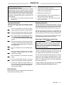
HOW THE ELECTROSTATIC AIR SPRAY GUN WORKS
The air hose supplies air to the spray gun. Part of the air
operates the turbine and the rest of the air atomizes the
fluid being sprayed. The turbine generates power, which
is converted by the power cartridge, to supply high
voltage current to the gun’s ionizing electrode.
The pump supplies fluid to the hose and gun, where the
fluid is electrostatically charged as it passes the electrode. The charged fluid is attracted to the grounded
workpiece, wrapping around and evenly coating all surfaces.
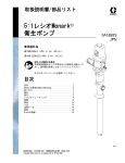
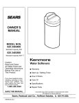
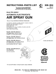
TYPICAL INSTALLATION
A
B
Power Supply Must Be Interlocked
With Spray Booth Exhaust Fan.
Electric Box
K
Main Air Line
P
E
Fluid Line
J
Cyl. Air
E
A
Atom. Air
WARNING
SIGN
Turbine Air
Opt. Remote Fan Air
F
A
J
C
D
L
G
J
Q
N
H
NON–HAZARDOUS AREA
HAZARDOUS AREA
KEY
A
B
C
D
E
Air Supply Shut-off Valve (bleed-type)
Air & Water Separator
Ball Valve
Air Line Lubricator
Air Regulator
F
G
H
J
K
Pump
Fluid Filter
Drain Valve
Pump Ground Wire
Air Filter (40 micron)
The Typical Installation shown above is only a guide for
selecting and installing electrostatic air spray systems. It
is not an actual system design. The particular type and
size system for your operation must be custom designed
for your needs. For assistance in designing a system,
contact your Graco representative.
WARNING
Installing and servicing this equipment requires access to parts which may cause electric shock or other
serious bodily injury if work is not performed properly.
Do not install or service this equipment unless
you are trained and qualified.
Be sure your installation complies with National,
State and Local codes for the installation of electrical
apparatus in a Class 1, Group D, Divisions 1 and 2
Hazardous Location.
Warning Signs
A warning sign in English and one in Spanish is supplied
with the gun. Mount warning signs in the spray area
where they can easily be seen and read by all operators.
This sign is also available in French and German. See the
ACCESSORIES section to order.
6
307-712
L
N
P
Q
Fluid Regulator
ES Automatic Gun
Normally Closed, 3-Way Air Solenoid
Valve or 3-Way Manual Valve
Exhaust Hose
Ventilate the Spray Booth
WARNING
To prevent hazardous concentrations of toxic and/
or flammable vapors, spray only in a properly ventilated spray booth. Never operate the spray gun
unless ventilation fans are operating. The air
supply to the gun must be electrically interlocked
with the ventilators to prevent operation of the
power supply unless ventilating fans are running.
Check and follow all of the National, State and Local codes regarding air exhaust velocity requirements.
Check and follow all local safety and fire codes and
OSHA standard 1910–107(b)(5)(i).
NOTE: High velocity air exhaust will decrease the operating efficiency of the electrostatic system. The
minimum allowable air exhaust velocity is 19 linear meters/minute (60 ft/min).
INSTALLATION
Mount the Gun
Mount the gun on a stationary support or on a reciprocating arm. The mounting rod must be properly grounded.
Mount the gun so the front of the gun is 254 to 300 mm (10
to 12 in.) from the work piece.
Connect the Air Line (Refer to the Typical
Installation Drawing)
WARNING
To reduce the risk of electric shock or other serious
bodily injury, the air supply hose must be electrically
connected to a true earth ground. Use Only Graco
Electrically Conductive Air Supply Hose. This
hose, and the gun, have special threads which prevent using any other type of hose with the gun. See
the ACCESSORIES section to order the hose.
1. Install an air line filter (K) and an air and water separator (B) on the main air line to ensure a dry, clean air
supply to the gun. Dirt and moisture can ruin the appearance of your finished workpiece and can cause
the gun to malfunction.
2. Install an air line lubricator (D) close to the pump air
inlet.
3. Install a normally closed, 3-way air solenoid (P) or
manual valve on the turbine, cylinder and remote fan
air supply lines. (The remote fan line is optional.)
4. Install a bleed-type air regulator (E) on the pump,
turbine, atomizing, cylinder, and remote fan (optional) air supply lines to control air pressure to the pump
and gun.
5. Install a bleed-type air shutoff valve (A) on the main
air line, the pump line, and each gun air supply line to
shut off air to the pump and gun.
WARNING
The bleed–type air shutoff valve (A) is required in
your system to relieve air trapped between this
valve and the pump after the air regulator is
closed. Trapped air can cause the pump to cycle
unexpectedly, which could result in serious bodily
injury, including splashing in the eyes or on the skin
and injury from moving parts.
6. Connect the cylinder air line to the gun’s cylinder air
inlet (marked CYL).
7. Connect the atomizing air line to the gun’s atomizing
air inlet (marked ATOM).
8. Connect the turbine air supply line to the gun’s air inlet (marked ES). The gun air inlet fitting has a left
hand thread. Connect the air supply hose ground
wire to a true earth ground.
9. A remote fan air adapter is available to control the fan
air at the control booth. See Installing the Optional
Remote Fan Air Adapter, on page 8.
Connect the Fluid Line (Refer to the Typical
Installation Drawing)
1. Before connecting the fluid line, blow it out with air
and flush it with solvent. Use solvent which is compatible with the fluid to be sprayed.
2. Install a fluid regulator (L) on the fluid line to control
fluid pressure to the gun.
3. Install a fluid filter (G) and drain valve (H) at the pump
outlet.
WARNING
The fluid drain valve (H) is required in your system
to assist in relieving fluid pressure in the displacement pump, hose and gun; triggering the gun to
relieve pressure may not be sufficient. Install a
drain valve close to pump’s fluid outlet. The drain
valve reduces the risk of property damage or serious bodily injury, including splashing in the eyes or
on skin and contamination from hazardous fluids.
4. Connect the fluid line to the gun fluid inlet.
CAUTION
Do not use metal fittings at the gun barrel. For circulation systems, use plastic fittings.
INSTALLATION
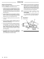
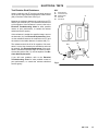
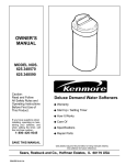
Check the Electrical Grounding
WARNING
Proper electrical grounding of every part of your
system is essential. For your safety, read the warning section, FIRE OR EXPLOSION HAZARD, on
page 5. Ground the system as explained there.
Then check your system as explained below.
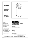
KEY
Y
Z
AA
BB
Turbine Air Inlet
True Earth Ground
Ohmmeter
Grounded Air Hose
AA
Z
1. Shut off all air lines to the gun.
2. Shut off the fluid supply to the gun.
3. Have a qualified electrician check the electrical
grounding continuity of the spray gun and air hose.
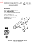
BB
a. With the electrically conductive air hose (BB)
connected and properly grounded, use a
megohmmeter (AA) (shown in ACCESSORIES
section) to measure the resistance between the
gun body (Y) and a true earth ground (Z). Use an
applied voltage of 500 volts minimum to 1000
volts maximum. See Fig 1.
b. If the resistance is greater than 2 megohms,
check the tightness of the ground connections,
and be sure the air supply hose ground wire is
connected to a true earth ground. If the resistance is still greater than 2 megohms, replace
the air supply hose.
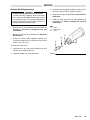
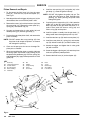
Installing Optional Remote Fan Air Adapter
NOTE: See ACCESSORIES to order the Remote Fan
Air Adapter 181–053 and 90 Elbow 108–234.
1. Place a wrench on the flats of the valve housing (55)
and remove the fan air valve assembly from the gun
body (1). See Fig 20, page 23.
Y
Fig 1
2. Apply PTFE tape to the threads of the remote fan air
adapter (part no. 181–053) and install it in the gun
body (1). Torque the adapter to 1.1–1.4 Nm (10–12
in-lb).
3. Install the 90 elbow (part no. 108–234) in the
adapter.
4. Install the remote fan air line, solenoid valve, air regulator and shut-off valve as instructed in Connect the
Air Lines, on page 7.
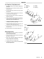
OPERATION
WARNING
Pressure Relief Procedure
2.
To reduce the risk of serious bodily injury, including
3.
splashing in the eyes or on the skin, injury from moving
parts or electric shock, always follow this procedure
when shutting off the system, when checking or serv4.
icing any part of the spray system, when installing,
5.
cleaning or changing fluid nozzles, and whenever you
stop spraying.
1. Turn off all the air to the gun except the cylinder
(actuating) air.
Turn off the fluid supply to the gun.
Trigger the gun into a grounded metal waste container to relieve fluid pressure.
Engage the gun safety latch.
Open the pump drain valve, having a waste container ready to catch the drainage.
6. Leave the pump drain valve open until you are
ready to spray again.
Operating Checklist
Spraying Operation
Check the following list daily, before starting to operate
the system, to help ensure you of safe, efficient
operation.
This gun has a built-in lead and lag operation. The gun
begins emitting air before the fluid is discharged. When
you release the trigger, the fluid stops before the air flow
stops. This helps prevent fluid build-up on the air cap.
1. Be sure all operators are properly trained to
safely operate an automatic air spray system.
2. Be sure all operators are trained how to properly and completely relieve system pressure.
3. Be sure the system is thoroughly grounded.
See FIRE OR EXPLOSION HAZARD, page
5, and Check the Electrical Grounding,
page 8.
4. Be sure the operator and all persons entering
the spray area are properly grounded by wearing shoes with conductive soles or personal
grounding straps.
5. Be sure ventilation fans are operating properly.
6. Be sure the work piece hangers are clean and
grounded. Contact points must be sharp
points or knife edges.
7. Be sure all refuse is removed from the spray
booth.
8. Be sure all flammable liquids in the spray
booth are in approved, grounded containers.
9. Be sure all conductive objects within 6 m
(20 ft) of the gun are electrically grounded and
the floor of the spray area is electrically conductive and grounded.
Adjust the system’s control device, if it is automatic, so
the gun starts spraying just before meeting the work
piece, and stops as soon as the work piece has passed.
When spraying, the ES indicator lights (BB) should glow,
indicating the electrostatic charge. See Fig 4.
Selecting a Fluid Nozzle and Air Cap
WARNING
To reduce the risk of serious bodily injury, including
splashing in the eyes or on the skin or electric
shock, always follow the Pressure Relief Procedure, above, before installing, or removing the fluid
nozzle/air cap assembly.
This gun is supplied with fluid nozzle 181–299 and air cap
180–739. See Instruction Manual 307–803 for air cap
consumption and fluid nozzle flow rate information.
The fluid output and pattern shape depends on the fluid
nozzle size, fluid viscosity, and fluid pressure. If your
application requires a different nozzle and air cap combination, use manual 307–803 to select the appropriate
fluid nozzle and air cap.
To install a different fluid nozzle and air cap, see To Clean
or Change Air Cap and Fluid Nozzle, page 12.
Filter the Fluid
Filter the fluid to remove coarse particles and sediment
which could clog the spray nozzle.
OPERATION
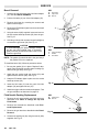
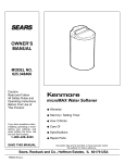
Adjust the Spray Pattern
Follow the steps below to establish the correct fluid flow
and air flow. DO NOT turn the turbine air on yet.
1. Adjust the fluid flow for the appropriate flow rate by
using the fluid pressure regulator installed in the fluid
line. Check the fluid nozzle chart in manual 307–803
for the appropriate flow rate for the air cap. Start with
the lowest rate shown and increase it until you get the
desired flow rate.
NOTE: Provide a 3.1 bar (45 psi) clean, dry, regulated air
supply to the gun to ensure full voltage from the
power supply. The gun may be operated at lower
turbine air pressure, but may lose some electrostatic effect. Do not operate the turbine at an air
pressure greater than 3.1 bar (45 psi) as there is
no benefit and turbine life will be reduced.
NOTE: A remote fan air adapter is available to control
the fan air at the control booth. See
ACCESSORIES.
2. For fine adjustment of how much fluid is sprayed,
tighten or loosen the trigger adjusting nut (24). See
Fig 4. Turn the nut out to reduce the amount of fluid
sprayed or turn it in to increase the amount.
KEY
3. Close the fan adjusting knob (56) by turning it fully
clockwise.
24
51
56
See the Spray Pattern Troubleshooting Chart
on page 13 to correct spray pattern problems.
Trigger Adjusting Nut
ES Indicator Light
Fan Adjusting Knob
51
4. Use an air pressure regulator to adjust the degree of
atomization. Always use the lowest air pressure possible for the most efficiency.
5. Use the fan adjusting knob to change the shape of
the spray pattern. Turn the knob counterclockwise
for a wide pattern and clockwise for a solid, round
pattern. When increasing to a wide, flat pattern, it
may be necessary to increase the supply of fluid to
the gun to maintain the same amount of coverage
over a large area.
6. First, complete all the checks under the Operating
Checklist on page 9. Then turn the turbine air on.
When spraying, the ES indicator light (51) should
glow, indicating the electrostatic charge.
Fig 2
Fig 3
Fig 4
24
56
MAINTENANCE
Daily Care and Cleaning
CAUTION
Clean all parts with a non–conductive solvent,
compatible with the fluid being sprayed. Conductive solvents can cause the gun to malfunction.
Do not use any cleaning method which may allow solvent into the gun air passages. Solvent
left in the gun passages could result in a poor quality paint finish and may draw current and reduce
the electrostatic effect. Point the gun down while
cleaning to prevent dirty solvent from running back
into the air passages. NEVER IMMERSE THE
GUN IN SOLVENT.
WARNING
For your safety, always follow the Pressure Relief
Procedure Warning on page 9 when shutting off
the system, when you stop spraying, and before
checking, servicing, installing, cleaning or changing any part in the system.
1. Clean the fluid and air line filters daily.
2. Check all of the work hangers for build-up of material;
clean them, if necessary.
3. All loose or ungrounded objects must be removed
from the spray booth.
4. Clean the outside of the gun daily with a soft cloth
dampened in a compatible solvent.
5. Flush the spray gun before changing fluids or colors
and whenever you are done operating the gun. See
Flush the Spray Gun.
6. Check the electrode wire. Straighten if bent, and replace if broken or damaged. See Electrode
Replacement.
7. Clean the air cap and spray nozzle daily, minimum;
some applications require more frequent cleaning.
Replace the spray nozzle and air cap if they are damaged. See To Clean or Change Air Cap and Fluid
Nozzle.
Flush the Spray Gun
WARNING
To reduce the risk of fire or explosion and serious
bodily injury, the turbine air (electrostatics) must
be off before flushing.
1. Follow the Pressure Relief Procedure Warning on
page 9.
2. Disconnect and plug the fluid line.
3. Connect the solvent supply to the gun.
4. Flush the gun with solvent until it is clean.
5. Follow the Pressure Relief Procedure Warning,
then disconnect the solvent supply.
6. Reconnect the fluid supply line.
8. Actuate the gun until it is clear of solvent.
MAINTENANCE
To Clean or Change Air Cap and Fluid Nozzle
CAUTION
Do not use metal tools to clean the air cap holes as
this may scratch them, and make sure the electrode wire is not damaged. Scratches in the air cap
holes or a damaged electrode wire can distort the
spray pattern.
KEY
15
BB
81
Fluid Nozzle
Air Cap Assembly
Locking Pin
BB
DETAIL
DETAIL
Equipment needed:
Soft bristle brush (supplied).
Fluid nozzle wrench (supplied).
Solvent compatible with fluid being sprayed.
15
Unlocked
Position
Locked
Position
Procedure:
1. Follow the Pressure Relief Procedure Warning on
page 9.
81
81
2. Remove the air cap assembly (BB). See Fig 6.
3. Turn the locking pin (81) to the unlocked position.
Fig 5
4. Squeeze the gun trigger and remove the fluid nozzle
(15) with the fluid nozzle wrench (66g) supplied.
Make sure the front of the gun is pointed down. See
Fig 6.
KEY
5. Use the soft bristle brush (66a) supplied and solvent
to clean the air cap, fluid nozzle, and front part of the
gun.
CC
15
16
66g
Electrode
Fluid Nozzle
Air Cap Assembly
Wrench
16
CC
6. Squeeze the gun trigger and screw the fluid nozzle
back into the gun. Tighten the nozzle securely with
the wrench (66g) supplied. Torque the fluid nozzle to
1.1–1.4 Nm (10–12 in–lb). See Fig 6. Turn the locking pin to the locked position.
15
Torque to
1.1–1.4 Nm
(10–12 in–lb)
7. Carefully reinstall the air cap assembly. Avoid bending the electrode (CC).
8. Tighten the retaining nut so it is snug. If the nut is tight
enough, you will feel resistance when turning the air
cap. If too tight, the spray pattern will be distorted.
66g
Fig 6
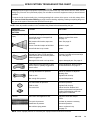
SPRAY PATTERN TROUBLESHOOTING CHART
WARNING
Installing and servicing this equipment requires access to parts which may cause electric shock or other serious
bodily injury if the work is not performed properly. Do not install or service this equipment unless you are trained and
qualified.
To reduce the risk of serious bodily injury, including splashing fluid or solvent in the eyes or on the skin, always follow
the Pressure Relief Procedure Warning on page 9 before checking, adjusting, cleaning or repairing the gun or
any part of the system. Disconnect the fluid hose from the gun.
NOTE: Check all possible remedies in the Troubleshooting Charts before disassembling the gun.
PROBLEM:
IMPROPER SPRAY
PATTERN
Fluttering or spitting
spray
Streaks
CAUSE
SOLUTION
Insufficient fluid supply.
Adjust fluid regulator or fill fluid tank.
Loose fluid nozzle or damaged fluid
nozzle taper seat.
Tighten or replace fluid nozzle
See page 12.
Dirt between fluid nozzle, taper seat
and body.
Clean. See page 12.
Loose or cracked coupler at fluid inlet.
Tighten or repair.
Loose fluid tube in cup or tank.
Tighten.
Fluid build-up on air cap; partially
clogged horn holes. Full air pressure
from clean horn hole forces fan pattern
toward clogged end.
Clean with soft implement or
submerge in suitable solvent and wipe
clean. See page 12.
Damaged fluid nozzle or air cap holes.
Replace damaged part. See page 12.
Fluid build-up on the perimeter of fluid
nozzle orifice, or partially clogged fluid
nozzle orifice.
Remove obstruction. Never use wire
or hard instruments. See page 12.
Too high atomization air pressure.
Reduce air pressure or adjust air
adjusting valve.
Fluid too thin.
Regulate fluid viscosity.
Not enough fluid pressure.
Increase fluid pressure.
Low atomization air pressure.
Increase air pressure.
Fluid too thick.
Regulate fluid viscosity.
Too much fluid.
Reduce fluid flow. Reduce fluid
pressure on pressure feed guns and/
or adjust fluid adjusting screw until
proper pattern is obtained.
Last coat of fluid applied too wet.
Apply drier finish with multiple
strokes.
Too much air pressure.
Use least air pressure necessary.
Insufficient air pressure.
Increase air pressure.
Non-uniform spray pattern.
Clean or replace air cap.
See page 12.
NOTE: Some improper patterns are caused by the improper balance between air and fluid.
GUN OPERATION TROUBLESHOOTING CHART
PROBLEM
CAUSE
SOLUTION
Leakage from fluid pack- Worn needle packing.
ing nut.
Replace packing assembly.
See page 20.
Air leakage from front
of gun.
Air valve not seating properly.
Clean, service. See page 24.
Air stem packing too tight.
Loosen packing. See page 24.
Fluid leakage from
front of gun.
Electrode worn or damaged.
Replace electrode. See page 18.
Worn fluid seat.
Replace fluid nozzle and/or electrode.
See page 18.
Fluid packing too tight.
Adjust packing screw. See page 20.
Loose fluid nozzle.
Tighten fluid nozzle. See page 12.
Cylinder air to gun not completely shut off.
Adjust screw.
Insufficient air pressure.
Increase, use least air pressure
needed for good results.
Fluid poorly mixed or filtered.
Remix or refilter fluid.
Improper thinner being used.
Use proper thinner.
Too much air pressure.
Reduce, use least air pressure
needed for good results.
Fluid thinned too much.
Properly thin fluid.
Fluid low.
Check, add if necessary.
Damaged air cap.
Replace air cap. See page 12.
Dirty or clogged fluid nozzle.
Clean fluid nozzle. See page 12.
Damaged fluid nozzle.
Check, replace fluid nozzle.
See page 12.
Air Valve not actuating.
Check cylinder air, fluid needle packing,
and needle. Replace parts as necessary.
See page 21.
Damaged fluid needle
Replace. See page 20.
Exhaust air flow insufficient or not directed
properly.
Check for proper CFM, check baffles
and direction of air flow.
Improper distance between gun and
work piece.
Adjust distance to 203–305 mm
(8–12 in.).
Misalignment between air cap and
fluid nozzle.
Remove and clean air cap and fluid
nozzle as described on page 12, then
reinstall them.
“Orange Peel” finish.
Excessive spray fog.
No fluid sprays from
gun.
Equipment covered
with fluid.
Dirty air cap.
ELECTRICAL TROUBLESHOOTING CHART
PROBLEM
CAUSE
SOLUTION
Poor wrap–around.
*Turbine alternator not operating.
Check air supply to turbine. Check for
dirt or moisture in turbine. See page 23.
Improper distance between gun
and workpiece.
Adjust spraying distance to
203–305 mm (8–12 in.).
Parts poorly grounded.
Clean hangers, check for proper
ground on conveyer or track.
High booth exhaust velocity.
Reduce within code limits.
Atomizing air pressure too high.
Reduce air pressure.
Fluid pressure too high.
Reduce fluid pressure.
Fluid viscosity.
Check supplier for proper fluid for
electrostatic spray.
Fluid resistivity too low.
Check fluid resistivity with paint
meter and probe.
Faulty gun resistance.
Check gun resistance. See page 16.
Faulty resistor stud resistance.
Check resistor stud resistance.
See page 17.
Faulty power supply resistance.
Check power supply resistance.
See page16.
Faulty electrode.
Replace electrode. See page 18.
*Faulty turbine alternator.
Be sure plug is in place on back of
turbine alternator housing.Remove and
test turbine alternator. See page 23.
Operator not properly grounded or is in
contact with ungrounded object.
Be sure floor is properly grounded.
Wear shoes with conductive soles
or wear personal grounding straps.
Be sure operator is not in contact
with or carrying any metallic items
which could build up electrical charge.
Gun not properly grounded.
See Check the Electrical Grounding,
page 8. Be sure Graco electrically conductive air supply hose is being used
and is properly grounded.
Work piece not properly
grounded.
Clean work piece hangers. Check for
proper ground on conveyor or track.
Operator gets mild
shock.
Operator gets mild
shock when touching
work piece.
*ES indicator light not on when gun is triggered.
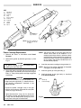
ELECTRICAL TESTS
The performance of the spray gun is directly affected by
the condition of the electrical components contained
inside the gun. The electrical tests below can be used to
determine the condition of the power supply (5) and the
resistor stud (17) as well as the continuity of the electrical
path between the components.
KEY
A
1
14
86
Megohmmeter
Gun Body
Electrode
Air Inlet Adapter
A
Use megohmmeter 218–979 (see ACCESSORIES) and
an applied voltage of 500 volts to complete these electrical tests. Connect the leads as shown.
WARNING
To reduce the risk of sparking, which could cause
fire or explosion and result in serious bodily injury,
DO NOT use the megohmmeter in the hazardous
area. Remove the gun from the hazardous area
before testing it.
1
86
Test Gun Resistance
NOTE: Check the resistance with the gun triggered and
untriggered.
Measure the resistance between the end of the electrode
(14) and the gun air inlet adapter (86). See Fig 7. The resistance should be between 115 to 152 megohms. If the
resistance is outside the specified range, go to the next
test. If the resistance is correct, refer to the Electrical
Troubleshooting Chart on page 15 for other possible
causes of poor performance.
Test Power Supply Resistance
Remove the power cartridge (2) from the gun body (1).
See Power Cartridge Replacement.
Remove the turbine alternator (2a) from the power supply (5). See Turbine Alternator Removal.
14
Fig 7
KEY
A
EE
2a
5
5c
Megohmmeter
Connector Prong
Turbine Alternator
Power Supply
Contact Spring
A
Measure the resistance from the center prong (EE) in the
power supply to the contact spring (5c) on the other end
of the power supply. See Fig 8.
The resistance should be 95 to 122 megohms. If the resistance is outside the specified range, the power supply
is defective and must be replaced. If the resistance of the
power supply is correct, proceed to the next test.
If you still have problems, refer to the Electrical
Troubleshooting Chart for other possible causes of
poor performance, or contact the nearest authorized
service agency.
EE
5c
Fig 8
5
2a
ELECTRICAL TESTS
Test Resistor Stud Resistance
Insert a conductive rod (FF) into the gun barrel (removed
for the power supply test) and against the metal contact
(GG) in the front of the barrel. See Fig 9.
KEY
A
FF
GG
14
20
Megohmmeter
Conductive Rod
Metal Contact
Electrode
Gun Barrel
A
Measure the resistance between the conductive rod (FF)
and the gun electrode (14). The resistance should be 20
to 30 megohms. If the resistance is correct, refer to the
Electrical Troubleshooting Chart for other possible
causes of poor performance, or contact the nearest
authorized service agency.
If the resistance is outside the specified range, remove
the electrode (14). See Electrode Replacement. Measure the resistance between the conductive rod (FF) and
the resistor in the inside diameter of resistor stud (17).
The resistance should be 20 to 30 megohms. If the resistance is correct, the electrode wire is defective and must
be replaced. See Electrode Replacement. If the resistance is outside the specified range, the resistor is defective and the resistor stud (17) must be replaced. See Resistor Stud Replacement.
If you still have problems, refer to the Electrical
Troubleshooting Chart for other possible causes of
poor performance, or contact the nearest authorized
service agency.
GG
20
FF
14
Fig 9
SERVICE
Gun Disassembly
WARNING
Installing and servicing this equipment requires
access to parts which may cause electric shock or
other serious bodily injury if the work is not performed properly. Do not install or service this
equipment unless you are trained and qualified.
2. Unscrew and remove the electrode (14) with the
wrench (66c) supplied. See Fig 10. If the needle shaft
assembly (9) turns while trying to loosen the electrode, hold the needle shaft assembly nut with a
small wrench.
3. Install the new electrode (14) with the wrench (66c).
Do not over tighten.
Follow the Pressure Relief Procedure Warning,
page 9, before servicing the gun or any part of the
system. Disconnect the fluid hose from the gun.
CAUTION
To avoid damaging the plastic threads, be very
careful when installing the electrode.
NOTE: Check all possible remedies in the
Troubleshooting Charts before disassembling
the gun.
4. Reinstall fluid nozzle and air cap assembly as
described in To Clean or Change Air Cap and
Fluid Nozzle.
CAUTION
If the plastic parts of the gun must be held securely, ALWAYS clamp them in padded vice jaws
to prevent damage to the parts.
KEY
9
66c
Fluid Needle Shaft Assembly
Wrench
66c
ALWAYS lubricate o–rings and seals with petroleum jelly.
9
ALWAYS remove gun from worksite for service or
repair. Service or repair area must be clean.
Flush the gun as described under Flush the Spray Gun.
Follow the Pressure Relief Procedure Warning on
page 9. Disconnect the air and fluid line from the gun.
Gun Assembly Note
Whenever you are tightening plastic parts where there is
no torque specified in the instructions, tighten the parts
finger-tight and then retighten with a wrench 1/4 to 1/2
turn.
Electrode Replacement
1. Remove the air cap assembly and fluid nozzle as described in To Clean or Change Air Cap and Fluid
Nozzle.
Fig 10
SERVICE
Resistor Stud Replacement
WARNING
Old/New Style Resistor Stud and Electrode
To reduce the risk of sparking, which could cause
fire or explosion, BE SURE the electrode and stud
you install are black. The old style electrode and
stud in the Series A Guns were white. DO NOT mix
old style parts with new style parts.
1. Remove the air cap assembly and fluid nozzle as
described in To Clean or Change Air Cap and
Fluid Nozzle.
3. Using the wrench supplied, install the resistor stud in
the front of the gun barrel. Tighten until snug.
4. Install the electrode as described in Electrode Replacement.
5. Install the fluid nozzle and air cap assembly as
described in To Clean or Change Air Cap and
Fluid Nozzle.
KEY
12
17
18
Washer
Resistor Stud
O-Ring
2. Remove the electrode as described in Electrode
Replacement.
12
18
3. Using the wrench (59h) supplied, unscrew and
remove the resistor stud (17) with the o-ring (18) and
washer (12). See Fig 11.
17
To install the resistor stud:
1. Lubricate the o-ring (18) with petroleum jelly and
install it on the resistor stud (17).
2. Install the washer (12) in the gun barrel.
Fig 11
SERVICE
Barrel Removal
1. Unscrew the nut (34) at the gun’s fluid inlet adapter
(35). See the PARTS DRAWING.
KEY
31
52
66f
Fluid Tube
Cap Screw
Wrench
2. Pull the fluid tube (31) out of the fluid adapter (35).
3. Remove the trigger by removing the screws and
spacers from the gun.
66f
4. Remove the ES indicator lights from the socket head
cap screws (52).
31
52
5. Using the wrench (66f) supplied, loosen and remove
the two socket head cap screws (52) from the gun.
See Fig 12.
6. Hold the gun body with one hand and pull straight up
to remove the gun barrel (20). See Fig 13.
CAUTION
To avoid damaging the power cartridge, always
pull the gun barrel straight away. If necessary,
gently move the gun barrel from side to side to free
it from the gun body.
Fig 12
KEY
2
6
20
Power Cartridge
Gasket
Gun Barrel
20
NOTE: The gasket (6) should be left in the gun body if
the gasket is not to be replaced.
6
To install the barrel (20), follow the procedure below:
1. Be sure the gasket (6) is in place. Replace if damaged. Place the barrel over the power cartridge (2)
and onto the gun body. See Fig 13.
2
2. Install the two socket head cap screws (52) and
tighten with the wrench (66f). See Fig 12.
3. Snap the ES indicator lights in place over the socket
head cap screws (52).
Fig 13
4. Insert the fluid tube (31) into the gun’s fluid inlet
adapter (35) and tighten the nut (34).
5. Install the trigger with the screws and spacers. Test
the gun resistance as instructed on page 16.
Fluid Needle Packing Replacement
1. Remove the air cap assembly and fluid nozzle as
described in To Clean or Change Air Cap and
Fluid Nozzle.
KEY
2. Remove the electrode as described under Electrode Replacement.
3. Remove the gun barrel as described under Barrel
Removal.
4. Unscrew the packing nut (9e) using the wrench (66b)
supplied. See Fig 14.
66b
9e
Packing Nut
66b Wrench
9e
Fig 14
SERVICE
!1%&4,,8 1%-/5% 3(% &,4)$ .%%$,% !22%-",8 &1/3(% 1%!1 0!13 /& 3(% '4. "!11%, %% )' & 3(%
0!#+).' !22%-",8 ! /1 ).24,!3/1 ' !1% 23),, ).
3(% "!11%, ).2%13 3(% 0!#+).' 1%-/5!, 1/$ $ ).3/
3(% &1/.3 /& 3(% "!11%, 3/ '%.3,8 042( 3(%- /43 %&%1
3/ )'
NOTE: & 3(% ).24,!3/1 ' )2 1%-/5%$ "% 241% 3/ ).23!,,
)3 2/ 3(% ).24,!3/1 %.$ 6)3( (/,%2 )2 &!#).' 3(%
0!#+).' !22%-",8 !
.23!,, 3(% !)1 #!0 !22%-",8 !.$ &,4)$ ./99,% !2
$%2#1)"%$ ). To Clean or Change Air Cap and
Fluid Nozzle
1)''%1 3(% '4. 3/ #(%#+ 3(% .%%$,% !$*423-%.3
(% !)1 2(/4,$ #/-% &4,,8 /. "%&/1% 3(% &,4)$ #/-%2
/. $*423 3(% .%%$,% !$*423).' .43 # 4.3), 3(%
01/0%1 ,%!$ !.$ ,!' )2 !#()%5%$
1%-/5% 3(% 31)''%1
!.$ "!#+ 3(% .%%$,% !$*423).' .43 # /43 !6!8
&1/- 3(% "!11%, 2,)'(3,8
)0% 3(% ).3%1.!, 241&!#%2 /& 3(% "!11%, #,%!. 6)3( !
2/&3 "142( /1 #,/3(
CAUTION
,%!. !,, 0!132 ). ./.:#/.$4#3)5% 2/,5%.3 #/-0!3:
)",% 6)3( 3(% &,4)$ "%).' 42%$ 24#( !2 78,/, /1 -).:
%1!, 20)1)32 2% /& #/.$4#3)5% 2/,5%.32 #!. #!42%
3(% '4. 3/ -!,&4.#3)/.
%-/5% 3(% 0!#+).' !22%-",8 ! &1/- 3(% .%%$,%
"
3)'(3%. 3(% .%%$,%
!$*423).' .43 # 2,)'(3,8 341. 3/6!1$2 "!11%,
&3%1 !$*423-%.3 )2 #/-0,%3% 3)'(3%. 3(% ,/#+).' .43
$ !'!).23 3(% !$*423).' .43 #
KEY
9
9c
20
,4)$ %%$,% 22%-",8
%%$,% $*423).' 43
4. !11%,
NOTE: & 3(% 0/2)3)/. /& 3(% !$*423).' .43 # )2
#(!.'%$ ).23!,, 3(% !$*423).' .43 3/ 3(% !0:
01/7)-!3% $)-%.2)/. 2(/6. ). )' ).!, !$:
*423-%.3 6),, "% -!$% ). 23%0 & 3(% 201).'
& 6!2 1%-/5%$ 1%).23!,, )3 /5%1 3(% .43 $
132.7 mm
(5.2 in.)
#
.23!,, 3(% .%6 0!#+).' !22%-",8 !
CAUTION
!1%&4,,8 2#1%6 .%%$,% " ).3/ .%6 0!#+).'
!22%-",8 ! 3/ !5/)$ $!-!').' 3(% 2%!,2
%23 3(% $1!' /. 3(% &,4)$ .%%$,% 3 2(/4,$ "% !0:
01/7)-!3%,8 3/ ,"2 42% ! 2-!,, 201).' 2#!,% 3/
-%!241% & 3(% !$*423-%.3 )2 /43 /& 3/,%1!.#%
3)'(3%. /1 ,//2%. 3(% !$*423).' 2#1%6 /. 3(% 0!#+:
).' !22%-",8 ! 2,)'(3,8 !.$ 1%3%23 /.3).4% 3/
!$*423 4.3), 3(% 3/,%1!.#% )2 #/11%#3
.23!,, 3(% %.3)1% &,4)$ .%%$,% !22%-",8 ).3/ 3(%
'4. "!11%, &1/- 3(% "!#+ /& 3(% "!11%,
)1-,8 3)'(3%. 3(% 0!#+).' .43 % $/6. 4.3), )3"/3:
3/-2
CAUTION
(%. #(%#+).' 3(% &,4)$ .%%$,% -/5%-%.3 -/5% 3(% .%%$,% /43 /& 3(% '4. "!11%, -/1%
3(!. -- ). 3/ !5/)$ 04,,).' 3(% .%%$,%
/43 /& 3(% 0!#+).' !1%! !.$ $!-!').' 3(% 0!#+:
).'2
Fig 15
KEY
9
9a
9b
9c
9d
9e
9f
9g
,4)$ %%$,% 22%-",8
%%$,% !#+).' 22%-",8
,4)$ %%$,%
$*423).' 43
/#+).' 43
!#+).' 43
01).'
.24,!3/1
$
#
&
"
%
'
.23!,, 3(% "!11%, !2 $%2#1)"%$ 4.$%1 Barrel
Removal
!
.23!,, 3(% %,%#31/$% !2 $%2#1)"%$ 4.$%1 Electrode
Replacement
Fig 16
307-712
21
SERVICE
KEY
1
2a
2b
2c
5
5a
5b
5c
6
20
2, -"5
*1#/,1-/
',%
*2%
-4#/ 2..*5
',%
',%
./',%
0)#1
//#*
!
## NOTE $1#/
01#. #*-4
NOTE: &# .-4#/ !/1/'"%# ',!*2"#0 '1#+0 ! ," !
Fig 17
Power Cartridge Replacement
#+-3# 1&#
Removal
//#* 0 "#0!/' #" 2,"#/ Barrel
#+-3# 1&# %0)#1 $/-+ 1&# %2, -"5 ##
'%
CAUTION
&# .-4#/ !/1/'"%# '0 $/%'*# # !/#$2* 4&#,
&,"*',% '1 1- 3-'" "+%#
/0. 1&# .-4#/ !/1/'"%# 4'1& 5-2/ &," '1& %#,1*# 0'"# 1- 0'"# +-1'-, .2** '1 $/## $/-+ 1&# %2,
-"5 &#, .2** 1&# .-4#/ !/1/'"%# 01/'%&1 -21
-$ 1&# -"5
CAUTION
20# 0-*3#,10 1- !*#, 1&# .-4#/ !/6
1/'"%# !3'15 ', 1&# %2, -"5 -*3#,1 4'** "+6
%# #*#!1/'!* !-+.-,#,10 !-,1',#" ', 1&#
.-4#/ !/1/'"%#
NOTE: &# !20&'-, '0 ./1 -$ 1&# %2, //#* ,"
0&-2*" ,#3#/ ,##" 1- # /#+-3#" $ '1 '0
/#+-3#" .20& 1&# !20&'-, ', "�'3# 0'"# 1-6
4/" 1&# //#* 4'1& /-" 2,1'* '1 '0 0#!2/#*5 "6
&#/#" ', 1&# //#* 20# 1&# .-4#/ 02.6
.*5 1- ./#00 1&# !20&'-, ',1- 1&# //#* 0 '1
4'** ,-1 "&#/# ./-.#/*5
,0#/1 1&# ,#4 .-4#/ !/1/'"%# ', 1&# %2, -"5 NOTE: ## '% $-/ ./-.#/ *'%,+#,1 -$ 1&# .-4#/
!/1/'"%# ', 1&# %2, -"5 ,01** 1&# %0)#1 ', 1&# %2, -"5 ,01** 1&# //#* -, 1&# %2,
2,"#/ Barrel Removal
KEY
1
2
2, -"5
-4#/ /1/'"%#
22
307-712
,0.#!1 1&# .-4#/ !/1/'"%# !3'15 ', 1&# %2,
-"5 $-/ "'/1 -/ +-'012/# *#, -21 1&# !3'15 4'1&
!*#, "/5 /% '$ ,#!#00/5
'%&1*5 *2 /'!1# 1&# -/',%0 -, 1&#
,#4 .-4#/ !/1/'"%# 4'1& .#1/-*#2+ (#**5 ** 1&#
-/',%0 ," 1&# !-+./#00'-, 0./',% ! +201
# ', .*!# -/ 1&# %2, 4'** +*$2,!1'-,
-"5 0 "#0!/' #"
Fig 18
SERVICE
Turbine Alternator Removal
Fan Air Valve Replacement
&.07& 108&3 $"353*%(& '30. 5)& (6/ #0%9 "4
%&4$3*#&% 6/%&3 Power Cartridge Replacement
-"$& " 83&/$) 0/ 5)& '-"54 0' 5)& 7"-7& )064*/( "/% 3&.07& *5 '30. 5)& (6/ #0%9 && *(
"3&'6--9 58*45 5)& 563#*/& "-5&3/"503 " "/% 16-- *5 0'' 5)& 108&3 4611-9 6/5*+645 %*4&/("(&% '30. 5)& $061-*/( )&/ $0/5*/6&
50 4-08-9 16-- 5)& 563#*/& "-5&3/"503 "8"9 '30. 5)&
108&3 4611-9 %*4$0//&$5*/( 5)& :8*3& $0//&$503
&& *( &.07& 5)& 3&5"*/*/( 3*/( 4*/( "/ 0)..&5&3 5&45 5)& $0*- */ 5)& 563#*/& "-5&3:
/"503 " &"463& 5)& 3&4*45"/$& #&58&&/ 5)& 580
065&3 5&3.*/"-4 0' 5)& :8*3& $0//&$503 )&
3&4*45"/$& 4)06-% #& 50 0).4 ' 5)& 3&"%*/( 7"3:
*&4 '30. 5)*4 7"-6& 3&1-"$& 5)& "-5&3/"503
-&"/ "-- 5)& 1"354 "/% */41&$5 5)&. '03 8&"3 03
%"."(& ' 3&1-"$*/( 5)& 4&"- 6/4$3&8 *5 "/% 3&.07& *5 '30. 5)& "%+645*/( 4$3&8
&"463& 5)& 3&4*45"/$& #&58&&/ &"$) 065&3 5&3.*:
/"- 0' 5)& :8*3& $0//&$503 "/% 5)& 563#*/& "-:
5&3/"503 )064*/( )& 3&4*45"/$& 4)06-% #& */'*/*5&
' 5)& 3&4*45"/$& *4 /05 */'*/*5& 3&1-"$& 5)& "-5&3/"503
"35*"--9 $0//&$5 5)& :8*3& $0//&$503 0/50 5)&
130/(4 */4*%& 5)& 108&3 4611-9 && *( 4:
*/( " 4."-- 4$3&8%3*7&3 164) 5)& $0//&$503 0/50 5)&
130/(4 6/5*- 4&"5&%
-*%& 5)& 563#*/& "-5&3/"503 " 0/50 5)& 108&3 461:
1-9 #&*/( 463& 50 "-*(/ 5)& $061-*/( #&58&&/ 5)&
108&3 4611-9 "/% 5)& 563#*/& "-5&3/"503 )064*/(
)&/ 58*45 5)& 563#*/& "-5&3/"503 50 -0$,
5)& $061-*/(
/45"-- 5)& 108&3 $"353*%(& */ 5)& (6/ #0%9 "4
%&4$3*#&% 6/%&3 Power Cartridge Replacement
KEY
HH
2a
5
8*3& 0//&$503
-5&3/"503
08&3 611-9
"
05"5& 5)& "*3 "%+645*/( 4$3&8 6/5*- *5 *4 %*4&/("(&% '30. 5)& 7"-7& )064*/(
5)3&"%4 6-- 5)& "%+645*/( 4$3&8 065 0' 5)& 7"-7&
)064*/(
11-9 .&%*6. (3"%& 5)3&"% 4&"-"/5 50 5)& 4."-5)3&"%4 0/ 5)& &/% 0' 5)& "%+645*/( 4$3&8 "/%
*/45"-- " /&8 4&"- -&'5 )"/% 5)3&"%
!)&/ 3&"44&.#-*/( 5)& '"/ "*3 7"-7& -6#3*$"5& 5)&
03*/( "/% 5)& "%+645*/( 4$3&8 5)3&"%4 8*5)
1&530-&6. +&--9
'5&3 5)& 3&5"*/*/( 3*/( *4 */45"--&% 0/ 5)& "%+645:
*/( 4$3&8 #"$, 5)& "%+645*/( 4$3&8 065 0' 5)&
7"-7& )064*/( 6/5*- *5 #0550.4 065 "("*/45 5)& 3&:
5"*/*/( 3*/(
11-9 &'-0/ 1"45& 50 5)& 5)3&"%4 0' 5)& 7"-7& )064:
*/( "/% */45"-- *5 */ 5)& (6/ #0%9 0326& 5)&
)064*/( 50 . */-#
KEY
1
46
47
54
55
56
6/ 0%9
&5"*/*/( */(
"-7& &":*/(
"-7& 064*/(
%+645*/( $3&8
Apply Teflon paste.
Torque to
1.1-1.4 Nm
(10-12 in-lb)
Fig 20
Fig 19
307-712
23
SERVICE
Piston Removal and Repair
8. Install the new packing (27) and guide (26) in the
gun body (1); screw the guide in loosely.
1. To disconnect the fluid hose (31) from the cover
plate (41), screw the nut (34) off the adapter (35).
See Fig 21.
NOTE: DO NOT fully tighten the guide (26) yet. The
guide must be loose to avoid damaging the
packing (27) when pushing the piston shaft
through the guide.
2. Note the position of the trigger adjusting nut (24) for
reinstallation, then screw it off the piston shaft.
9. If replacing the uĆcup packing (37), slide it onto the
piston (42) so the lips of the packing will face toĆ
wards the front of the gun when the piston is inĆ
stalled. Then install the bunaĆn oĆring (30) and
Viton oĆring (79) on the piston.
3. Remove the screws (61) and lock washers (82) from
the cover plate (41). Remove the cover plate (41),
spring (38), and retainer cap (74).
4. Unscrew and remove the air valve guide (26) and
needle packing (27) from the gun body (1),
10. Install the piston assembly into the gun body (1),
being careful not to damage the piston's lip seal.
5. Push on the end of the piston shaft, and remove the
piston assembly.
11. Install the retainer cap (74) into the cover plate (41).
NOTE: DO NOT remove the uĆcup packing (37) from
the piston shaft except to replace it as removal
will damage this packing.
12. Install the cover plate (41), spring (38), and retainer
cap (74) with the screws (61) and lock washers (82).
13. Actuate the trigger and tighten the air valve guide
(26) with a wrench.
6. Clean and inspect parts for wear or damage. ReĆ
place parts as needed.
14. Screw the trigger adjusting nut (24) onto the piston
shaft to its previously noted position.
7. When reassembling the piston assembly, lubricate
the oĆrings (30 & 79) and the uĆcup packing (42) on
the piston with petroleum jelly. Pack the spring (38)
with petroleum jelly. Apply Teflon tape to the air valve
guide (26).
KEY
1
24
26
27
30
31
Gun Body
Trigger Adjusting Nut
Air Valve Guide
Needle Packing
BunaĆn OĆRing
Fluid Tube
34
35
37
38
41
Nut
Adapter
UĆCup Packing
Spring
Cover Plate
15. Connect the fluid hose (31) to the adapter (35).
42
61
74
79
82
Piston
Screws
Retainer Cap
Viton OĆRing
Lock Washers
42
37
1
74
79
41
35
38
30
Apply
Teflon
tape
61
26
24
27
31
Fig 21
24
82
307-712
34
Pack with
lubricant
SERVICE
Disc Regulator OĆRing Replacement
04%3'8 5*' 563$+0' #+3 .+0' (31/ 5*' #'3 '' +) '/17' 5*' %#2 4%3'8 #0& 8#4*'3 (31/
5*' )60 $1&9 KEY
1
3
85
86
60 1&9
')6.#513 +4+0)
'3
6.. 5*' #'3 8+5* 5*' #+3 7#.7' 165 1(
5*' )60 $1&9
04%3'8 5*' #'3 (31/ 5*' #+3 7#.7' #0& 3'/17' 5*' &+4- 3')6.#513 87
88
89
90
:+0)
+3 !#.7'
"#4*'3
#2 %3'8
.'#0 #0& +042'%5 2#354 (13 8'#3 13 &#/#)' #0&
3'2.#%' +( 0'%'44#39
.'#0 #0& +042'%5 5*' 581 1:3+0)4 #0& 10' 1:
3+0) 10 5*' #+3 7#.7' '2.#%' +( 0'%'44#39 6:
$3+%#5' 5*' 1:3+0)4 8+5* 2'531.'6/ ,'..9
045#.. 5*' &+4% 3')6.#513 +051 5*' #+3 7#.7' 41
+54 $'7'.'& 463(#%' (#%'4 +051 5*' )60
%3'8 5*' #'3 +051 5*' #+3 7#.7' #0&
+045#.. 5*' #+3 7#.7' +051 5*' )60 $1&9 %3'8 5*' %#2 4%3'8 8+5* 5*' 8#4*'3 +051
5*' )60 $1&9 %3'8 5*' 563$+0' #+3 .+0' 1051 5*' #'3 Fig 22
KEY
1
76
77
78
60 1&9
6((.'3
.$18
6$'
Muffler Replacement
'/17' 5*' (#0 #+3 7#.7' #44'/$.9 #4 +04536%5'& +0
Fan Air Valve Replacement
'/17' 5*' '.$18 8+5* 5*' 56$' (31/ 5*'
)60 $1&9 '' +) "+5* # *11- 3'/17' 5*' /6((.'3 (31/ 5*' )60
$1&9 #0& 3'2.#%' 8+5* # 0'8 /6((.'3
045#.. 5*' '.$18 +0 5*' )60 $1&9
045#.. 5*' (#0 #+3 7#.7' #44'/$.9 #4 +04536%5'& +0 Fan
Air Valve Replacement
Fig 23
307-712
25
26
16b
5c
20b
5b
16c
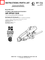
Includes items
2a–2c & 5
16a
Ref No. 2
Power Cartridge
66b
66c
66d
66h
66f
81
80
5
14
66a
66g
66e
Ref No 66, Tool Kit
Includes items 66a–66h
*5a
15
17
12
24
REF 42
2a
85
60
20a
**11
91
53
*2b
See
DETAIL A
23
50
18*
2c
Screw in restrictors
flush with surface
of gun body
86
3
*87
21
20
27
26
88
*6
4
36
1
51
28
52
9a
36
41
89 90
84
31
9g
77
82
76
9e
61 79
75
34
78
30*
9b
33
9c
37*
35
9
9d
47
42
9f
56
DETAIL A
46
55
38
74
54
PARTS DRAWING
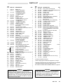
PARTS LIST
REF
NO.
PART NO.
DESCRIPTION
1
2
218–744
218–111
2a
217–591
2b*
2c
3*
4
5
107–106
180–070
107–107
110–916
218–041
5a*
5b*
5c
6*
9
177–156
106–555
178–504
179–387
222–256
9a
9b
9c
9d
9e
9f
9g
11**
12
14
15
222–255
222–013
183–749
183–750
176–936
105–673
179–388
179–790
181–825
181–824
181–299
16
218–996
16a
16b
16c
176–930
176–968
180–739
17
220–923
105–667
1
BODY, gun
POWER CARTRIDGE
Includes items 2a & 5
1
.ALTERNATOR, turbine
Includes items 2b & 2c
1
..O–RING; buna–N
2
..PLUG
1
REGULATOR, disc
1
1
SCREW; 1/4–20
.POWER SUPPLY, ES, 75 KV
Includes items 5a, 5b & 5c
1
..O–RING; Viton
1
..O–RING; fluorocarbon
1
..SPRING, compression
1
GASKET, housing
1
FLUID NEEDLE ASSY; Includes
items 9a–9g
1
.PACKING ASSY, needle
1
.NEEDLE, fluid; Includes items 9c & 9d 1
..NUT, adjusting
1
1
..NUT, locking
.NUT, packing
1
.SPRING, compression
1
.INSULATOR, needle
1
LABEL, warning
1
WASHER
1
ELECTRODE (color coded black)
1
NOZZLE, fluid; 1.2 mm (0.047’’)
(See manual 307–803 for other
available fluid nozzles)
1
AIR CAP ASSEMBLY
Includes items 16a, 16b & 16c
1
.RING, retaining
1
.NUT, retaining
1
.AIR CAP (See manual 307–803
for other available air caps)
1
STUD, resistor (color coded black)
1
O–RING; Viton; standard
(color coded green)
1
O–RING, polyethylene; optional
(color coded white)
1
BARREL, gun; Includes item 20a & 20b 1
.PLUG; M3 x 0.5 x 6
1
.CUSHION
1
FITTING, male
1
TRIGGER
1
NUT, adjusting, trigger
1
GUIDE, valve, air
1
PACKING, needle;PTFE
1
ELBOW, male
1
O–RING; buna–N
1
TUBE, fluid
1
TAG, warning (not shown)
1
COLLAR
1
NUT, tube, flareless
1
ADAPTER, fluid
1
18*
108–045
20
20a
20b
21
23
24
26
27*
28
30*
31
32**
33
34
35
179–412
176–921
186–127
107–207
180–928
180–927
176–941
106–901
108–173
156–454
181–179
179–791
178–131
106–262
181–384
QTY
WARNING
Old/New Style Resistor Stud and Electrode
To reduce the risk of sparking, which could cause fire
or explosion, BE SURE the electrode and stud you
install are black. The old style electrode and stud in
the Series A Guns were white. DO NOT mix old style
parts with new style parts.
REF
NO.
36
37*
38
41
42
46
47
50
51
52
PART NO.
107–208
181–039
108–221
180–924
218–989
105–681
181–383
180–235
218–179
107–100
53
54*
55
56
60
61
62
65
179–994
105–666
181–382
181–381
107–400
100–205
180–060
180–063
66
66a
66b
66c
66d
66e
66f
66g
66h
74
75
76
77
78
79
80
81
82
84
85
86
87*
88
89
90
91
220–388
105–749
177–732
177–007
179–803
107–158
107–460
177–004
183–107
181–178
181–599
181–594
181–223
054–134
108–298
181–302
181–303
108–340
104–282
105–796
181–598
103–648
181–597
102–782
105–408
177–128
DESCRIPTION
QTY
3
NUT, ferrule; 5/8–20 UN–2B
PACKING, u–cup; UHMW polyethylene 1
SPRING, compression
1
PLATE, cover
1
PISTON, shaft
1
RING, retaining, external
1
SEAL, valve
1
RESTRICTOR (color coded black)
1
LIGHT, indicator, ES
2
SCREW, cap, socket hd;
M5 x 0.8 x 12
2
RESTRICTOR (color coded white)
1
O–RING; ethylene–propylene
1
HOUSING, valve
1
SCREW, adjusting
1
SCREW, trigger
2
SCREW, mach, pnh; 6–32
4
SIGN, warning, English (not shown)
1
SIGN, warning, Spanish (not shown);
See ACCESSORIES to order French
or German
1
KIT, tool; Includes items 66a–66h
1
.BRUSH, cleaning
1
.WRENCH, packing nut
1
.WRENCH, needle
1
.ROD, packing removal
1
.WRENCH, resistor stud
1
.WRENCH, barrel
1
.WRENCH, fluid nozzle
1
TOOL, resistor stud
1
CAP, retainer, spring
1
PLUG; 3/8–18 npsm
1
ELBOW, male, 905
1
MUFFLER
1
TUBE, polyethylene
178 mm
O–RING; Viton
1
HOUSING, pin
1
PIN, locking
1
LOCKWASHER, internal
4
O–RING; buna–N
1
O–RING; Viton
1
ADAPTER; 1/4–18 npsm, LH
1
O–RING; Viton
2
VALVE, air
1
WASHER, plain
1
SCREW, cap, hex hd; M6 x 10 long
1
SPACER
2
*Included in Repair Kit 218–967.
**Extra warning tags and labels are supplied at no charge.
Included in Repair Kit 220–391. Read and follow the Old/New
Style Resistor Stud and Electrode Warning, at left.
See HOW TO ORDER REPLACEMENT PARTS on page 29.
WARNING
When servicing use only genuine Graco replacement parts. Use of other parts or any alteration or
modification of this equipment could cause it to
malfunction, which could result in serious injury,
fire, explosion, or property damage.
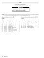
KITS
Repair Kits must be purchased separately.
Use only GENUINE GRACO PARTS AND ACCESSORIES.
WARNING
When servicing use only genuine Graco replacement parts. Use of other parts or any alteration or
modification of this equipment could result in serious
injury, fire, explosion, or property damage.
NOTE: The Ref. Nos. shown in the kits below correspond to the reference numbers used in the parts list on page 27.
For the best results, use all the parts in the kit, even if the old parts still look good.
Spray Gun Repair Kit 218–967
Resistor Stud and Electrode Kit 220–391
Includes:
Includes:
Ref
No.
Part No.
2b
3
5a
5b
6
18
27
30
37
54
87
107–106
107–107
177–156
106–555
179–387
105–667
106–901
156–454
181–039
105–666
103–648
Description
O-RING, buna-n
REGULATOR, disc
O-RING, Viton
O-RING, Viton
GASKET, housing
O-RING, Viton
PACKING, needle, PTFE
O-RING, buna-n
PACKING, u-cup, UHMWPE
O-RING, ethylene-propylene
O-RING, Viton
Qty
2
1
1
1
1
1
1
2
1
1
2
Ref
No.
Part No.
12
14
17
181–825
181–824
220–923
18
66c
66h
105–667
177–007
183–107
Description
Qty
WASHER
ELECTRODE (color coded black)
STUD, resistor (color coded
black)
O–RING, Viton
WRENCH, needle
TOOL, resistor stud
1
1
1
1
1
1
TECHNICAL DATA
SERVICE INFORMATION
Weight . . . . . . . . . . . . . . . . . . . . . . . . . . . 0.87 Kg (1.90 lb)
Gun Length . . . . . . . . . . . . . . . . . . . . . 310 mm (12.25 in.)
Maximum Working Pressure . . . . . . . . . . 7 bar (100 psi)
Air Pressure Operating Range . . . 0–7 bar (0–100 psi)
Fluid Pressure Operating Range . 0–7 bar (0–100 psi)
Voltage Operating Range . . . . . . . . . . . . . . . . . . 0–75 KV
Paint Resistivity Range . . . . 7 megohm cms to infinity
Air Inlet
Turbine . . . . . . . . . . . . . . . . . . . . . . 1/4 npsm(m) L.H.
Atomizing & Cylinder . . . . . . . . . . . . . . . . 1/4 npt(m)
Fluid Inlet . . . . . . . . . . . . . . . . . . . . . . . . . . . 3/8 npsm(m)
Wetted Parts . . . . . . Stainless Steel, Polyethylene,
Nylon, Acetal, Viton,
Delrin
Listed below by assembly changed are OLD and NEW
parts.
Assembly
Changed Status
218–745
OLD
Spray Gun NEW
Ref
No. Part No.
4
4
100–664
110–916
Name
Screw
Screw
Vitonand Delrin are registered trademarks of
the DuPont Co.
HOW TO ORDER REPLACEMENT PARTS
1. To be sure you receive the correct replacement
parts, kits or accessories, always give all of the
information requested in the chart below.
2. Check the parts list to identify the correct part
number; do not use the ref. no. when ordering.
3. Order all parts from nearest Graco distributor.
6 digit
Part
Number
Qty
Part Description
ACCESSORIES
Accessories must be purchased separately.
Use only GENUINE GRACO PARTS AND ACCESSORIES.
WARNING
NEVER operate your equipment at a working pressure rating that is higher than the lowest rated component in
your system. Lower rated components may not be able to withstand the pressure developed by the pump and may
rupture, causing serious bodily injury or property damage.
The accessories in the box, below, are approved by Factory Mutual.
WARNING SIGNS
Available from Graco at no extra charge.
Must be ordered separately.
FLUID HOSE ASSEMBLIES (Nylon)
35 bar (500 psi) MAXIMUM WORKING PRESSURE
6.35 mm (0.25 in.) ID, 3/8 npsm(fbe)
Warning Sign (English)
Warning Sign (French)
Warning Sign (German)
Warning Sign (Spanish)
180–060
180–061
180–062
180–063
GROUNDED AIR SUPPLY HOSE
7 bar (100 psi) MAXIMUM WORKING PRESSURE
6.35 mm (0.25 in.) ID, 1/4 npsm(fbe)
220–444
218–100
218–101
218–102
218–103
220–119
220–120
1.2 m (4 ft)
5 m (15 ft)
8 m (25 ft)
11 m (36 ft)
15 m (50 ft)
23 m (75 ft)
30.5 m (100 ft)
216–076
216–077
216–078
216–079
216–080
8 m (25 ft)
15 m (50 ft)
23 m (75 ft)
30 m (100 ft)
46 m (150 ft)
FLUID HOSE ASSEMBLIES (Nylon)
14 bar (225 psi) MAXIMUM WORKING PRESSURE
6.35 mm (0.25 in.) ID, 3/8 npsm(fbe)
215–637
215–638
215–639
215–640
215–641
8 m (25 ft)
15 m (50 ft)
75 ft (23 m)
100 ft 30.5 m)
150 ft (46 m)
ACCESSORIES
The accessories below and on page 31 have not been tested by Factory Mutual.
AIR LINE ACCESSORIES
GROUNDED AIR SUPPLY HOSE
7 bar (100 psi) MAXIMUM WORKING PRESSURE
8 mm (0.315 in.) ID; 1/4 npsm(fbe);
Color coded gray; More flexible than black hose
223–068
223–069
223–070
223–071
223–072
223–073
223–074
1.2 m (4 ft)
5 m (15 ft)
8 m (25 ft)
11 m (36 ft)
15 m (50 ft)
23 m (75 ft)
30.5 m (100 ft)
AIR HOSE ADAPTER 185–493
For connecting two or more air supply hoses together.
1/4 npt(m) x 1/4 npsm(m) left–hand thread.
3-WAY AIR VALVE 722–502
HIGH VOLUME AIR REGULATOR 206–199
0–9 bar (0–125 psi) Regulated Pressure
14 bar (200 psi) Steel Pressure Gauge
1/2 npt(f) inlet and outlet
AIR FILTER & MOISTURE SEPARATOR 106–148
17.5 bar (250 psi) MAXIMUM WORKING PRESSURE
For cleaning and drying air in air spray system.
20 micron element, 5 oz. bowl capacity,
3/8 npt(f) inlet and outlet
ACCESSORIES
FILTER (AIR OR PAINT) 202–271
52 bar (750 psi)MAXIMUM WORKING PRESSURE
With 250 micron (60 mesh) element,
3/8 npt(f) inlet, 3/8 npt(m) outlet
GUN MOUNTING ACCESSORIES
UNIVERSAL GUN MOUNTING ROD 590–236
RECIPROCATING GUN MNTG. BRACKET 725–973
Note: All safety barriers and interlocks are to be
supplied by the customer.
STATIONARY GUN MOUNTING STAND 722–562
SPRAY SYSTEM ACCESSORIES
ELECTROSTATIC SYSTEM 231–035
Includes items:
218–745
218–101
216–076
tion)
106–148
Automatic Electrostatic Air Spray Gun
Grounded Air Supply Hose (See
page 30 for description)
Fluid Hose (See page 30 for descripAir Filter (See page 30 for description)
STATIONARY GUN MOUNTING BRACKET 724–344
MISCELLANEOUS ACCESSORIES
REMOTE FAN AIR ADAPTER 181–053
To control fan pattern from the control booth. 1/8–27
npt(f).
Must also order: 108–234 90 Elbow; 1/8 npt(m)
REMOTE SWITCH & SIGNAL LIGHT 728–386
ELECTROSTATIC SYSTEM 231–036
Includes items:
218–745
218–103
216–077
106–148
Automatic Electrostatic Air Spray Gun
Grounded Air Supply Hose (See
and page 30 for description)
Fluid Hose (See page 30 for description)
Air Filter (See page 30 for description)
ISOLATION STAND
Required for isolating the fluid supply from the ground
when spraying conductive water-base fluid.
728–650 Isolation Stand; 15 gal (57 liter) maximum
727–212 Isolation Stand; 55 gal (209 liter) maximum
905–576 Same as 727–212 but includes bleed
resistor
WATER BASE PACKING KIT 220–014
For converting packings to handle water base fluids.
NOTE: The installation of this kit will void the CSA and
FM approval on the PRO4000 Gun.
CONTROL PANEL 218–394
For one or two gun operation. Includes cabinet mounted
air regulator, air filter, three-way triggering valve and air
atomizing gauge.
PAINT RESISTANCE METER 722–886
Used with 722–860 Paint Probe to measure resistance of
paint. Not for use in Hazardous areas.
PAINT PROBE 722–860
Used with 722–886 Paint Resistance Meter to
measure resistance of paint. Not for use in
Hazardous areas.
MEGOHMMETER 218–979
500 Volt output; 0.01–2000 megohms
THE GRACO WARRANTY AND DISCLAIMERS
WARRANTY
Graco warrants all equipment manufactured by it and bearing its name to be free from defects in material and workmanship on the date of sale by an authorized Graco distributor to the original purchaser for use. As purchaser’s sole
remedy for breach of this warranty, Graco will, for a period of twelve months from the date of sale, repair or replace
any part of the equipment proven defective. This warranty applies only when the equipment is installed, operated
and maintained in accordance with Graco’s written recommendations.
This warranty does not cover, and Graco shall not be liable for, any malfunction, damage or wear caused by faulty
installation, misapplication, abrasion, corrosion, inadequate or improper maintenance, negligence, accident, tampering, or substitution of non–Graco component parts. Nor shall Graco be liable for malfunction, damage or wear
caused by the incompatibility with Graco equipment of structures, accessories, equipment or materials not supplied
by Graco, or the improper design, manufacture, installation, operation or maintenance of structures, accessories,
equipment or materials not supplied by Graco.
This warranty is conditioned upon the prepaid return of the equipment claimed to be defective to an authorized
Graco distributor for verification of the claimed defect. If the claimed defect is verified, Graco will repair or replace
free of charge any defective parts. The equipment will be returned to the original purchaser transportation prepaid. If
inspection of the equipment does not disclose any defect in material or workmanship, repairs will be made at a reasonable charge, which charges may include the costs of parts, labor and transportation.
DISCLAIMERS AND LIMITATIONS
THE TERMS OF THIS WARRANTY CONSTITUTE PURCHASER’S SOLE AND EXCLUSIVE REMEDY AND ARE IN LIEU OF
ANY OTHER WARRANTIES (EXPRESS OR IMPLIED), INCLUDING WARRANTY OF MERCHANTABILITY OR WARRANTY
OF FITNESS FOR A PARTICULAR PURPOSE, AND OF ANY NON–CONTRACTUAL LIABILITIES, INCLUDING PRODUCT LIABILITIES, BASED ON NEGLIGENCE OR STRICT LIABILITY. EVERY FORM OF LIABILITY FOR DIRECT, SPECIAL OR CONSEQUENTIAL DAMAGES OR LOSS IS EXPRESSLY EXCLUDED AND DENIED. IN NO CASE SHALL GRACO’S LIABILITY EXCEED THE AMOUNT OF THE PURCHASE PRICE. ANY ACTION FOR BREACH OF WARRANTY MUST BE BROUGHT
WITHIN TWO (2) YEARS OF THE DATE OF SALE.
EQUIPMENT NOT COVERED BY GRACO WARRANTY
GRACO MAKES NO WARRANTY, AND DISCLAIMS ALL IMPLIED WARRANTIES OF MERCHANTABILITY AND FITNESS FOR
A PARTICULAR PURPOSE, WITH RESPECT TO ACCESSORIES, EQUIPMENT, MATERIALS, OR COMPONENTS SOLD BUT
NOT MANUFACTURED BY GRACO. These items sold, but not manufactured by Graco (such as electric motor,
switches, hose, etc.) are subject to the warranty, if any, of their manufacturer. Graco will provide purchaser with reasonable assistance in making any claim for breach of these warranties.
IMPORTANT PHONE NUMBERS
TO PLACE AN ORDER, contact your Graco distributor, or call this number to identify the distributor closest
to you:
1–800–328–0211 Toll Free
FOR TECHNICAL ASSISTANCE, service repair information or assistance regarding the application of Graco
equipment: 1–800–543–0339 Toll Free
Factory Branches: Atlanta, Chicago, Dallas, Detroit, Los Angeles, West Caldwell (N.J.)
Subsidiary and Affiliate Companies: Canada; England; Switzerland; France; Germany; Hong Kong; Japan
GRACO INC.
P.O. BOX 1441 MINNEAPOLIS, MN 55440–1441
PRINTED IN U.S.A. 307–712 7–85 Revised 9–90