1
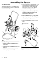
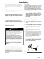
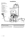
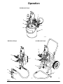
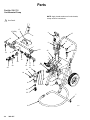
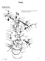
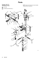
INSTRUCTIONS-PARTS LIST
This manual contains important
warnings and information.
READ AND KEEP FOR REFERENCE.
308–367
Rev. B
Supersedes Rev. A
First choice when
and PCN B
quality counts.
INSTRUCTIONS
23:1 RATIO
Monark Sprayers
2760 psi (19.0 MPa, 190 bar) Maximum Fluid Working Pressure
120 psi (0.84 MPa, 8.4 bar) Maximum Air Inlet Pressure
Part No. 236–721
Cart Mounted pump
Part No. 236–722
Pail Mounted Pump
Part No. 236–723
Wall Mount Pump
GRACO INC.
P.O. BOX 1441 MINNEAPOLIS, MN
COPYRIGHT 1994, GRACO INC.
Graco Inc. is registered to I.S. EN ISO 9001
55440–1441
Table of Contents
Warnings . . . . . . . . . . . . . . . . . . . . . . . . . . . . . . . . . . . . . . 2
Assembling the Sprayer . . . . . . . . . . . . . . . . . . . . . . . . . 4
Installation . . . . . . . . . . . . . . . . . . . . . . . . . . . . . . . . . . . . 5
Operation . . . . . . . . . . . . . . . . . . . . . . . . . . . . . . . . . . . . . 7
Parts . . . . . . . . . . . . . . . . . . . . . . . . . . . . . . . . . . . . . . . . 10
Technical Data . . . . . . . . . . . . . . . . . . . . . . . . . . . . . . . . 15
Warranty . . . . . . . . . . . . . . . . . . . . . . . . . . . . . . . . . . . . . 16
Graco Phone Number . . . . . . . . . . . . . . . . . . . . . . . . . . 16
Symbols
Warning Symbol
WARNING
This symbol alerts you to the possibility of serious
injury or death if you do not follow the instructions.
Caution Symbol
CAUTION
This symbol alerts you to the possibility of damage to
or destruction of equipment if you do not follow the
corresponding instructions.
WARNING
INJECTION HAZARD
Spray from the gun, hose leaks, or ruptured components can inject fluid into your body and cause an
extremely serious injury, including the need for amputation. Splashing fluid in the eyes or on the skin
can also cause a serious injury.
Fluid injected into the skin might look like just a cut, but it is a serious injury. Get immediate medical attention.
Do not point the spray gun at anyone or at any part of the body.
Do not put hand or fingers over the spray tip.
Do not stop or deflect fluid leaks with your hand, body, glove, or rag.
Always have the tip guard and the trigger guard on the spray gun when spraying.
Check the gun diffuser operation weekly. Refer to the gun manual.
Be sure the gun trigger safety operates before spraying.
Lock the gun trigger safety when you stop spraying.
Follow the Pressure Relief Procedure on page 7 whenever you: are instructed to relieve pressure; stop spraying; clean, check, or service the equipment; and install or clean the spray tip.
Tighten all the fluid connections before operating the equipment.
Check the hoses, tubes, and couplings daily. Replace worn, damaged, or loose parts immediately.
Permanently coupled hoses cannot be repaired; replace the entire hose.
TOXIC FLUID HAZARD
Hazardous fluids or toxic fumes can cause a serious injury or death if splashed in the eyes or on the
skin, swallowed, or inhaled.
Know the specific hazards of the fluid you are using. Read the fluid manufacturer’s warnings.
Store hazardous fluid in an approved container. Dispose of the hazardous fluid according to all
local, state, and national guidelines.
Wear appropriate protective clothing, gloves, eyewear, and respirator.
308–367
WARNING
EQUIPMENT MISUSE HAZARD
INSTRUCTIONS
Equipment misuse can cause the equipment to rupture, malfunction, or start unexpectedly and result
in a serious injury.
This equipment is for professional use only.
Read all the instruction manuals, tags, and labels before operating the equipment.
Use the equipment only for its intended purpose. If you are uncertain about usage, call your Graco
distributor.
Do not alter or modify this equipment. Use only genuine Graco parts and accessories.
Check the equipment daily. Repair or replace worn or damaged parts immediately.
Do not exceed the maximum working pressure of the lowest rated system component. This equipment has a 2760 psi (19.0 MPa, 190 bar) maximum fluid working pressure at 120 psi (0.84
MPa, 8.4 bar) incoming air pressure.
Use fluids that are compatible with the equipment wetted parts. See the Technical Data section of
all the equipment manuals. Read the fluid manufacturer’s warnings.
Route the hoses away from traffic areas, sharp edges, moving parts, and hot surfaces. Do not
expose Graco hoses to temperatures above 180F (82C) or below –40F (–40C).
Comply with all applicable local, state, and national fire, electrical, and other safety regulations.
FIRE AND EXPLOSION HAZARD
Improper grounding, poor air ventilation, open flames, or sparks can cause a hazardous condition and
result in fire or explosion and serious injury.
Ground the equipment and object being sprayed. See Grounding on page 5.
Provide fresh air ventilation avoid the buildup of flammable fumes from solvent or the fluid being
sprayed.
Extinguish all the open flames or pilot lights in the spray area.
Electrically disconnect all the equipment in the spray area.
Keep the spray area free of debris, including solvent, rags, and gasoline.
Do not turn on or off any light switch in the spray area while operating or if fumes or present.
Do not smoke in the spray area.
Do not operate a gasoline engine in the spray area.
If there is any static sparking while using the equipment, stop spraying immediately. Identify and
correct the problem.
308–367
3
Assembling the Sprayer
Cart Mounted Pump
Assemble the suction hose (6) to the elbow (5) at the
pump intake. Screw the suction tube (7) onto the other
end of the hose. See Fig. 1.
4. Screw the elbow (22) into the pump air inlet, so the
female threads face down. Apply sealant to both
ends of the hose (23). Connect one end to the
elbow (22), then connect the other end to the
swivel (24) at the pump air regulator (F).
5. Unscrew the filter bowl (T) from the top cap (U).
Apply sealant to the threads of the nipple (14) and
install the nipple and top cap in the pump outlet.
Lubricate the threads of the filter bowl (T) and
screw it into the top cap (U) tightly.
6. Mount the wall bracket 5 ft (1.5 m) above the floor.
Be sure the wall is strong enough to support the
weight of the pump and accessories, fluid, hoses,
and stress caused during pump operation. Refer to
manual 306–783 for further information.
7. Screw the suction kit swivel (13) onto the pump
intake.
1
Apply thread sealant.
22
7
G
25
1
29
S F 25
7
23
14
5
6
1
36
34
30
1
24
U
T
03356
Fig. 1
13
Wall Mount Pump
1. Screw the gauges (25) into the air regulators (F,
G). See Fig. 2.
2. Connect the nipple (34) and bleed valve (30) to the
swivel (36).
3. Install the air manifold assembly (S) to the wall
bracket (7) using the two screws (29).
4
308–367
03357
Fig. 2
Pail Mounted Pump
The pail mounted pump is shipped completely assembled.
Installation
Be sure that all operators read and understand this
entire manual and the separate manuals supplied with
components and accessories before using this equipment.
Reference numbers and letters in parentheses refer to
the figures and parts drawings.
Accessories mentioned are available from your Graco
distributor. If you supply your own accessories, be sure
they area adequately sized to meet your system’s
requirements.
Grounding
To reduce the risk of static sparking, ground the pump,
object being sprayed, and all other spray equipment
used or located in the spray area. Check you local
electrical code for detailed grounding instructions for
your area and type of equipment. Be sure to ground all
of this spray equipment.
1. Pump: loosen the grounding lug locknut (W) and
washer (X). Insert one end of a 1.5 mm2 (12 ga)
minimum ground wire (Y) into the slot in lug (Z)
and tighten the locknut securely. See Fig. 3. Connect the other end of the ground wire to a true
earth ground.
2. Air hoses: use only grounded air hoses.
The Typical Installation shown in Fig. 4 is only an
example. For assistance in designing a system to meet
your particular needs, contact your Graco distributor.
System Accessories
3. Fluid hoses: use only grounded fluid hoses.
4. Air compressor: follow manufacturer’s recommendations.
5. Spray gun: grounding is obtained through connection to a properly grounded fluid hose and pump.
6. Fluid supply container: according to your local
code.
WARNING
Two required components are supplied with your
pump, to help reduce the risk of serious injury
including fluid injection, splashing in the eyes or on
the skin, or injury from moving parts if you are
adjusting or repairing the pump.
The bleed-type master air valve (B) relieves air
trapped between this valve and the pump. Trapped
air can cause the pump to cycle unexpectedly. To
bleed air from the pump, the pump air regulator
(F) must be open when you close this valve.
The fluid drain valve (H) assists in relieving fluid
pressure in the displacement pump, hose, and gun;
triggering the gun to relieve pressure may not be
sufficient.
7. Object being sprayed: according to your local
code.
8. All solvent pails used when flushing, according to
local code. Use only metal pails, which are conductive, placed on a grounded surface. Do not
place the pail on a non-conductive surface, such
as paper or cardboard, which interrupts the
grounding continuity.
9. To maintain grounding continuity when flushing or
relieving pressure, always hold a metal part of the
spray gun firmly to the side of a grounded metal
pail, then trigger the spray gun.
X
Y
Install an air line filter (E) in the main air line, to remove harmful dirt and moisture from the compressed
air supply. To provide automatic lubrication of the air
motor, install an air line lubricator (P) downstream from
the pump air regulator (F). Install a second master air
valve (D) in the main air line, to isolate the accessories
for servicing.
W
Z
Fig. 3
308–367
5
Installation
D
Typical Installation –
Cart Mount Model Shown
E
KEY
A
B
Pump
Bleed-Type Master Air Valve
(required for pump)
C Air Supply Line
D Master Air Valve (for accessories)
E Air Line Filter
F Pump Air Regulator
G Gun Air Regulator
H Fluid Drain Valve (required)
J Fluid Suction Line
K Fluid Filter
L Gun Fluid Supply Hose
M Gun Air Supply Hose
N Air-Assisted Airless Spray Gun
P Air Line Lubricator
R Fluid Intake Elbow
Y Ground Wire (required; see page 5
for installation instructions)
NOTE: Some components shown are
included with the sprayer, depending on the
model. Refer to the parts lists on pages 10–15
for parts included in your sprayer.
A
Y
F
N
B
P
M
G
M
L
C
L
K
H
R
J
Fig. 4
Hose and Gun Connections
Refer to Fig. 4. Connect one end of the fluid hose (L)
to the fluid filter (K) outlet and the other to the fluid inlet
of the spray gun (N). Do not install the spray tip in the
gun yet.
6
308–367
Close the bleed-type master air valve (B) and the air
regulators (F, G). Connect a grounded air hose (M)
between the outlet of the gun air regulator (G) and the
air inlet of the spray gun (N). The pump air regulator
(F) is connected to the pump (A) with a hose (C).
Operation
Pressure Relief Procedure
WARNING
INJECTION HAZARD
Fluid under high pressure can be injected through the skin and cause
serious injury. To reduce the risk of an
injury from injection, splashing fluid, or moving
parts, follow the Pressure Relief Procedure
whenever you:
are instructed to relieve the pressure,
stop spraying,
check or service any of the system equipment,
or install or clean the spray tips.
1. Engage the spray gun safety latch.
2. Close the bleed-type master air valve (supplied in
your system).
Flush the Pump Before Using
Pumps are tested with lightweight oil which is left in to
protect the pump parts. To prevent contamination of
the fluid, flush the pump with a compatible solvent
before using it.
WARNING
Before flushing, be sure the entire system and
flushing pails are properly grounded. Refer to
Grounding on page 5. Follow the Pressure
Relief Procedure at left, and remove the spray tip
from the gun. Always use the lowest possible fluid
pressure, and maintain firm metal-to-metal contact
between the gun and the pail during flushing to
reduce the risk of fluid injection, static sparking,
and splashing in the eyes or on the skin.
3. Shut off the air regulators.
4. Disengage the spray gun safety latch.
5. Hold a metal part of the spray gun firmly to the
side of a grounded metal pail, and trigger the spray
gun to relieve pressure.
6. Engage the spray gun safety latch.
7. Open the drain valve (supplied in your system),
having a container ready to catch the drainage.
8. Leave the drain valve open until you are ready to
spray again.
If you suspect that the spray tip or hose is completely
clogged, or that pressure has not been fully relieved
after following the steps above, very slowly loosen the
tip guard retaining nut or hose end coupling and relieve
pressure gradually, then loosen completely. Now clear
the tip or hose.
308–367
7
Operation
Starting and Adjusting the Pump
WARNING
To reduce the risk of serious injury whenever you
are instructed to relieve pressure, always follow the
Pressure Relief Procedure on page 7.
See Fig. 5. Be sure the air regulators (F, G) and bleedtype master air valve (B) are closed. Do not install
the spray tip yet.
On cart mount units, place the suction tube (7) in the
fluid container.
On wall mount units, screw the bung adapter (18) into
the container’s bung hole. Slide the suction tube
assembly (J) through the bung adapter and into the
container. Position the tube so the intake housing (1) is
about 1/2 in. (13 mm) off the bottom of the container.
Tighten the thumbscrew (26) to secure.
On pail mount units, fill the pail (46) with fluid. Set the
cover (36) on the pail and secure with the latches (40).
Open the drain valve (H) to prime the pump. Open the
bleed-type master air valve (B). Open the gun air
regulator (G). Hold a metal part of the spray gun firmly
to the side of a grounded metal pail and trigger the
gun.
Slowly open the pump air regulator (F) until the pump
starts. Run the pump slowly until fluid comes from the
drain valve (H). Close the drain valve and continue to
run the pump until all the air is pushed out of the fluid
lines. Release the gun trigger and engage the safety
latch; the pump will stall against the pressure.
With the pump and lines primed, and with adequate air
pressure and volume supplied, the pump will start and
stop as the spray gun is triggered and released.
Relieve the pressure, then install the spray tip in the
gun.
8
308–367
Use the pump air regulator (F) to control the pump
speed and fluid pressure. Always use the lowest
pressure necessary to achieve the desired results.
Higher pressures waste fluid and cause premature
wear of the pump packings and spray tip.
Keep the packing nut/wet-cup filled with Graco Throat
Seal Liquid (TSL) to help prolong the packing life.
Check the tightness of the packing nut weekly. The
packing nut should be tight enough to prevent leakage
– no tighter. Always relieve the pressure before
adjusting the packing nut.
Never allow the pump to run dry of the fluid being
pumped. A dry pump will quickly accelerate to a high
speed, possibly damaging itself. If you pump accelerates quickly, or is running too fast, stop it immediately
and check the fluid supply. If the supply container is
empty and air has been pumped into the lines, refill the
supply container and prime the pump and lines with
fluid, being sure to eliminate all air from the fluid system, or flush the pump as described in Shutdown and
Care, below.
Shutdown and Care
WARNING
To reduce the risk of serious injury whenever you
are instructed to relieve pressure, always follow the
Pressure Relief Procedure on page 7.
Always relieve the pressure whenever you shut off
the pump. Stop the pump at the bottom of its stroke to
keep fluid from drying on the exposed displacement
rod and damaging the throat packings.
Always flush the pump with a compatible solvent
before fluid can dry on the displacement rod, and at
the end of each day. Relieve the pressure after
flushing.
Operation
Pail Mounted Pumps
F
H
36
G
40
46
03145A
Wall Mount Pumps
Cart Mounted Pumps
G
G
F
B
B
H
H
F
18
J
7
26
Fig. 5
1
03142
03140
308–367
9
Parts
Part No. 236–721
Cart Mounted Pump
NOTE: Apply thread sealant to all male threads,
except at swivel connections.
See Detail.
37 (Ref)
17
4
37
18
47
2
26
16
19
15 (Ref)
25
11
1
A
3
12
28
10
29
13
30
14
10
24
19
A
15
9
10 23 8
5
31
32
7
6
10
308–367
Parts
Ref
No.
Part No.
Description
15
204–560
16
101–180
2
17
102–254
2
2
18
166–999
19
20
162–453
206–994
23
155–665
24
25
26
28
100–840
188–595
165–472
222–297
29
30
158–491
107–142
31
32
150–286
210–658
2
37
224–044
1
47
160–790
HOSE, air; buna-N; 3/8” (10 mm) ID;
cpld 3/8 npt(mbe); 18” (457 mm) long 1
GAUGE, air pressure;
0–200 psi (0–1.4 MPa, 0–14 bar)
2
SCREW, hex hd; 1/4–20 x
7/8” (22 mm) long
2
ELBOW, street, reducing;
1/2 npt(m) x 1/4 npt(f)
1
NIPPLE; 1/4 npt x 1/4 npsm
2
THROAT SEAL LIQUID;
8 oz (0.5 liter); not shown
1
UNION, swivel; 3/8 npt(m) x
3/8 npsm(f)
1
1
ELBOW; 1/4 npt (m x f)
1
BRACKET, pump mounting
1
ELBOW, 90; 3/8 npt(fbe)
UNION, adapter, 45;
1/2 npt(m) x 1/2 npsm(f) swivel
1
NIPPLE; 1/2 npt; 1.625” (41 mm) long 1
VALVE, air, bleed-type;
1/2 npt (m x f)
1
ADAPTER; 3/8 npt (m x f)
1
BALL VALVE; 3/8 npt(mbe); carbon steel
See manual 306–861 for parts
1
CART, portable
See manual 308–136 for parts
1
NIPPLE; 3/8 npt; 3.625” (92 mm) long 1
Part No. 236–721
Cart Mounted Pump
Ref
No.
Part No.
Description
1
2
100–016
100–022
3
4
100–015
223–596
LOCKWASHER, spring; 1/4”
CAPSCREW, hex hd;
1/4–20 x 3/4” (19 mm) long
NUT, hex; 1/4–20
MONARK PUMP
See manual 307–619 for parts
ELBOW, fluid intake; 3/4 npt(fbe)
HOSE, suction, fluid; nylon
3/4 npt(mbe); 3/4” (19 mm) ID;
3.5 ft (1.06 m) long
TUBE, suction; 3/4 npt(f); aluminum
NIPPLE; 3/8 npt
FLUID FILTER; carbon steel
See manual 307–273 for parts
PLUG, pipe, sq hd; 1/4 npt
MANIFOLD, air; 1/2 npt inlet
two 1/2 npt outlets
NIPPLE; 1/2 npt; 2.5” (63.5 mm)
AIR REGULATOR
0–125 psi (0–0.9 MPa, 0–9 bar) range
See manual 308–167 for parts
UNION, adapter, 90;
1/2 npt(m) x 3/8 npsm(f) swivel
5
6
100–349
214–960
7
8
9
165–767
156–849
218–029
10
11
100–509
179–749
12
13
156–877
104–267
14
161–037
Qty.
1
1
1
1
1
1
4
1
2
Qty.
308–367
11
Parts
Part No. 236–722
Pail Mounted Pump
28
NOTE: Apply thread sealant to all male threads,
except at swivel connections.
29
52
23
22
51
18
20
14
49
24
6
25
15
7
49
16
31
17
29
19
18
32
31
17 (Ref)
31
5
B
4
3
33
49
34
32
B
31
12
A
50
A
30
10
5 (Ref)
9
25
6
26
7
43
39
36
40
35
44
13
29
18
45
41
12
42
46
308–367
Parts
Part No. 236–722
Pail Mounted Pump
Ref
No.
Part No.
Description
3
171–987
4
5
156–823
202–812
6
101–180
7
104–267
9
10
12
13
160–516
165–096
104–765
166–999
14
223–596
15
104–429
16
17
156–971
206–966
18
19
20
162–453
164–259
164–720
22
155–665
TEE; 3/8 npt(f) x 1/4 npt(f) run;
3/8 npt(f) branch
UNION, swivel; 1/4 npt(m) x 1/4 npt(f)
HOSE, air; neoprene; 1/4” (6 mm) ID;
cpld 1/4 npt(mbe); 1.2 ft (0.36 m) long
GAUGE, air pressure;
0–200 psi (0–1.4 MPa, 0–14 bar)
AIR REGULATOR
0–125 psi (0–0.9 MPa, 0–9 bar) range
See manual 308–167 for parts
O-RING; nitrile rubber
PLUG, inspection hole
PLUG, pipe; 1/8 npt
ELBOW, street, reducing;
1/2 npt(n) x 1/4 npt(f)
MONARK PUMP
See manual 307–619 for parts
CAPSCREW, hex hd;
1/4–20 x 2.25 in. (57 mm)
NIPPLE; 1/4 npt
HOSE, fluid; PTFE 1/4” (6 mm) ID;
1/4 npsm(fbe); 12.5” (318 mm) long
NIPPLE; 1/4 npt x 1/4 npsm
ELBOW, street; 3/8 npt(m) x 1/4 npt(f)
ELBOW, outlet; 3/4 npt(m) x
3/8 npt(m) x 1/4 npt(f)
UNION, swivel; 3/8 npt(m) x
3/8 npsm(f)
Qty.
1
1
1
Ref
No.
Part No.
Description
23
218–029
24
210–657
25
26
27
156–684
101–380
206–994
28
29
30
31
104–813
100–721
218–693
100–933
32
33
34
35
206–755
164–726
156–593
101–962
36
39
179–917
161–395
40
41
42
43
205–535
204–534
158–223
100–063
44
45
46
49
50
100–016
100–015
101–108
159–239
107–142
51
52
150–286
100–840
FLUID FILTER; carbon steel;
See manual 307–273 for parts
BALL VALVE; 3/8 npt x 1/4 npt (mbe);
See manual 306–861 for parts
UNION, swivel; 1/2 npt(m) x 1/2 npt(f)
BUTTON, plug
THROAT SEAL LIQUID;
8 oz (0.5 liter); not shown
PLUG, pipe; 3/8 npt
PLUG, pipe; 1/4 npt
BASE, mounting, pump
SCREW, type F self-tapping
No. 8–32 x 3/16” (5 mm)
CORD, wire; 5/5” (140 mm) long
PLUG, inspection hole
O-RING; nitrile rubber
SCREW, socked hd set;
1/4–20 x 3/8” (10 mm)
COVER, pail
PIN, pivot; 1/4” (6 mm) dia.;
2” (51 mm) long
HANDLE, latch, cover
HOOK, latch, cover
WASHER; steel
PIN, cotter; 0.06” (1.6 mm) dia.;
1/2” (13 mm) long
LOCKWASHER, spring; 1/4”
NUT, hex; 1/4–20
PAIL
NIPPLE, reducing; 1/2 npt x 3/8 npt
VALVE, air, bleed-type;
1/2 npt (m x f)
ADAPTER
ELBOW, street
2
2
1
1
1
1
1
2
1
1
3
1
1
1
Qty.
308–367
1
1
2
1
1
1
3
1
2
2
1
1
2
1
2
2
2
2
2
2
2
1
3
1
1
1
13
Parts
Part No. 236–723
Wall Mount Pump
NOTE: Apply thread sealant to all male threads,
except at swivel connections.
See Detail.
Included with wall bracket (7).
31
5
7 (Ref)
29
22
25
23 (Ref)
32
19
A
20
36
34
17
30
21
14
24
7
17
23
32
A
15
13
17
28
3
12
16
10
18
11
B
26
3 (Ref)
9
B
4
1
14
308–367
Parts
Part No. 236–723
Wall Mounted Pump
Ref
No.
Part No.
Description
1
3
159–101
214–961
4
5
161–377
223–596
7
207–365
8
206–994
9
10
11
159–100
156–593
156–592
12
156–591
13
156–589
14
15
156–850
218–029
HOUSING, suction tube intake
1
HOSE, suction, fluid; nylon
3/4 npt(mbe); 3/4” (19 mm) ID;
6 ft (1.83 m) long
1
SCREEN, suction tube intake
1
MONARK PUMP
See manual 307–619 for parts
1
BRACKET, wall
See manual 306–783 for parts
1
THROAT SEAL LIQUID
9 oz (0.5 liter); not shown
1
1
STOP, ball
O-RING, buna-N
1
TUBE, suction; 1–1/2 uns–2a (mbe);
carbon steel
1
ELBOW, 90; 3/4 npt x
1–1/2 uns–2b (fbe)
1
ADAPTER swivel, fluid intake, 90;
3/4 npt(f) x 3/4 npt(f) swivel
1
NIPPLE; 3/8 npt
1
FLUID FILTER; carbon steel
See manual 307–273 for parts
1
BALL VALVE; 3/8 npt(mbe); carbon steel
See manual 306–861 for parts
1
PLUG, pipe, sq hd; 1/4 npt
4
16
210–658
17
100–509
Qty.
Ref
No.
Part No.
Description
18
19
176–684
179–749
20
21
156–877
104–267
22
23
155–699
204–560
24
161–037
25
101–180
26
100–220
27
28
29
110–110
150–286
102–254
30
107–142
31
166–999
32
34
36
162–453
158–491
222–297
ADAPTER, bung
MANIFOLD, air; 1/2 npt inlet;
two 1/2 npt outlets
NIPPLE; 1/2 npt; 2.5” (63.5 mm)
AIR REGULATOR
0–125 psi (0–0.9 MPa, 0–9 bar) range
See manual 308–167 for parts
ELBOW, street, 90; 3/8 npt(m x f)
HOSE, air; buna-N; 3/8” (10 mm) ID;
cpld 3/8 npt(mbe); 18” (457 mm) long
UNION, adapter, 90;
1/2 npt(m) x 3/8 npsm(f) swivel
GAUGE, air pressure
0–200 psi (0–1.4 MPa, 0–14 bar)
THUMBSCREW; 5/16–18 unc;
1” (25 mm) long
SEALANT, pipe
ADAPTER; 3/8 npt(m x f)
SCREW, hex hd; 1/4–20 x
7/8” (22 mm) long
VALVE, air, bleed-type;
1/2 npt (m x f)
ELBOW, street, reducing;
1/2 npt(m) x 1/4 npt(f)
NIPPLE; 1/4 npt x 1/4 npsm
NIPPLE; 1/2 npt; 1.625” (41 mm) long
UNION, adapter, 45;
1/2 npt(m) x 1/2 npsm(f) swivel
Qty.
1
1
2
2
1
1
1
2
1
1
1
2
1
1
2
1
1
Technical Data
Category
Data
Maximum working pressure
2760 psi (19.0 MPa, 190 bar)
Maximum incoming air pressure
120 psi (0.84 MPa, 8.4 bar)
Ratio
23:1
Wetted parts – Pump
See manual 307–619
Wetted parts – Fluid Filter
See manual 307–273
Wetted parts – Fluid Fittings
Carbon Steel
Manual Change Summary
This manual was revised to include the changes from PCN B.
308–367
15
The Graco Warranty
Graco warrants all equipment listed in this manual which is manufactured by Graco and bearing its name to be free from defects in
material and workmanship on the date of sale by an authorized Graco distributor to the original purchaser for use. With the exception of
any special extended or limited warranty published by Graco, Graco will, for a period of twelve months from the date of sale, repair or
replace any part of the equipment determined by Graco to be defective. This warranty applies only when the equipment is installed,
operated and maintained in accordance with Graco’s written recommendations.
This warranty does not cover, and Graco shall not be liable for general wear and tear, or any malfunction, damage or wear caused by
faulty installation, misapplication, abrasion, corrosion, inadequate or improper maintenance, negligence, accident, tampering, or
substitution of non-Graco component parts. Nor shall Graco be liable for malfunction, damage or wear caused by the incompatibility of
Graco equipment with structures, accessories, equipment or materials not supplied by Graco, or the improper design, manufacture,
installation, operation or maintenance or structures, accessories, equipment or materials not supplied by Graco.
This warranty is conditioned upon the prepaid return of the equipment claimed to be defective to an authorized Graco distributor for
verification of the claimed defect. If the claimed defect is verified, Graco will repair or replace free of charge any defective parts. The
equipment will be returned to the original purchaser transportation prepaid. If inspection of the equipment does not disclose any defect
in material or workmanship, repairs will be made at a reasonable charge, which charges may include the costs of parts, labor, and
transportation.
Graco’s sole obligation and buyer’s sole remedy for any breach of warranty shall be as set forth above. The buyer agrees that no other
remedy (including, but not limited to, incidental or consequential damages for lost profits, lost sales, injury to person or property, or any
other incidental or consequential loss) shall be available. Any action for breach of warranty must be brought within two (2) years of the
date of sale.
GRACO MAKES NO WARRANTY, AND DISCLAIMS ALL IMPLIED WARRANTIES OF MERCHANTABILITY AND FITNESS FOR
A PARTICULAR PURPOSE IN CONNECTION WITH ACCESSORIES, EQUIPMENT, MATERIALS OR COMPONENTS SOLD BUT
NOT MANUFACTURED BY GRACO. These items sold, but not manufactured by Graco (such as electric motors, gas engines,
switches, hose, etc.), are subject to the warranty, if any, of their manufacturer. Graco will provide purchaser with reasonable assistance
in making any claim for breach of these warranties.
In no event will Graco be liable for indirect, incidental, special or consequential damages resulting from Graco supplying equipment
hereunder, or the furnishing, performance, or use of any products or other goods sold hereto, whether due to a breach of contract,
breach of warranty, the negligence of Graco, or otherwise.
FOR GRACO CANADA CUSTOMERS
The parties acknowledge that they have required that the present document, as well as all documents, notices and legal proceedings
entered into, given or instituted pursuant hereto or relating directly or indirectly hereto, be drawn up in English. Les parties
reconnaissent avoir convenu que la rédaction du présente document sera en Anglais, ainsi que tous documents, avis et procédures
judiciaires exécutés, donnés ou intentés à la suite de ou en rapport, directement ou indirectement, avec les procédures concernées.
Graco Phone Number
TO PLACE AN ORDER, contact your Graco distributor, or call this number to identify the distributor closest to you:
1–800–367–4023 Toll Free.
All written and visual data contained in this document reflects the latest product information available at the time of publication.
Graco reserves the right to make changes at any time without notice.
Sales Offices: Minneapolis, Detroit, Los Angeles
Foreign Offices: Belgium, Canada, England, Korea, France, Germany, Hong Kong, Japan
GRACO INC.
P.O. BOX 1441 MINNEAPOLIS, MN
PRINTED IN U.S.A.
16
308–367
55440–1441
308–367 May 1994, Revised July 1997