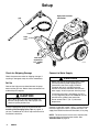
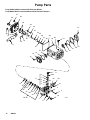
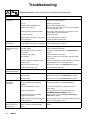
1
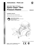
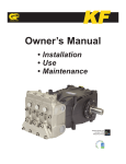
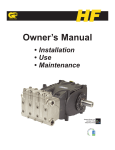
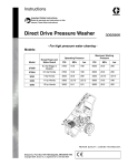
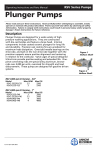
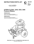
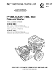
INSTRUCTIONS–PARTS LIST
308524
Rev. K
This manual contains important
warnings and information.
READ AND KEEP FOR REFERENCE.
INSTRUCTIONS
Parts
Belt-Drive Pressure Washers
2545
Model 800629, Series B
2500 psi (17.2 MPa, 172 bar) Operating Pressure
2900 psi (20 MPa, 200 bar) Maximum Working Pressure
3040
Model 800632, Series B
3000 psi (20.6 MPa, 206 bar) Operating Pressure
3400 psi (23.4 MPa, 234 bar) Maximum Working Pressure
3235
Model 800634, Series B
3200 psi (22.1 MPa, 221 bar) Operating Pressure
3600 psi (24.8 MPa, 248 bar) Maximum Working Pressure
04607
3040 Pressure Washer
Model 800632
GRACO INC.
P.O. BOX 1441
MINNEAPOLIS, MN
ECOPYRIGHT 1995, GRACO INC.
Graco Inc. is registered to I.S. EN ISO 9001
55440–1441
Table of Contents
Warnings . . . . . . . . . . . . . . . . . . . . . . . . . . . . . . . . . . . . . .
Setup . . . . . . . . . . . . . . . . . . . . . . . . . . . . . . . . . . . . . . . . .
Operation . . . . . . . . . . . . . . . . . . . . . . . . . . . . . . . . . . . . .
Pressure Relief Procedure . . . . . . . . . . . . . . . . . . . . . . .
Pump Service . . . . . . . . . . . . . . . . . . . . . . . . . . . . . . . . . .
2
4
5
5
8
Pressure Washer Parts Drawing and List . . . . . . . . .
Pump Parts Drawing and List . . . . . . . . . . . . . . . . . . .
Troubleshooting . . . . . . . . . . . . . . . . . . . . . . . . . . . . . . .
Technical Data . . . . . . . . . . . . . . . . . . . . . . . . . . . . . . . .
Graco Standard Warranty . . . . . . . . . . . . . . . . . . . . . .
Graco Phone Number . . . . . . . . . . . . . . . . . . . . . . . . . .
10
12
14
15
16
16
Symbols
Warning Symbol
Caution Symbol
WARNING
CAUTION
This symbol alerts you to the possibility of serious
injury or death if you do not follow the instructions.
This symbol alerts you to the possibility of damage to
or destruction of equipment if you do not follow the
instructions.
WARNING
WARNING
INJECTION HAZARD
Spray from the gun, leaks or ruptured components can inject fluid into your body and cause serious
injury. Fluid splashed in the eyes or on the skin can also cause serious injury.
D Fluid injected into the skin may look like just a cut, but it is a serious injury. Get emergency
medical attention.
D Do not point the gun at anyone or at any part of the body.
D Do not stop or deflect leaks with hand, body, glove, or rag.
D Do not put your hand or fingers over the spray tip.
D Tighten fluid connections before you start this equipment.
D Engage the gun trigger safety when you stop spraying.
D Follow Pressure Relief Procedure on page 5 if the spray tip clogs and before you clean,
check, or service this equipment.
D Repair or replace worn or damaged parts immediately.
D Check hoses, tubes, and couplings daily. Do not repair high-pressure couplings; you must replace
the entire hose. Fluid hoses must have spring guards on both ends to prevent kinks and rupture.
2
308524
WARNING
WARNING
MOVING PARTS HAZARD
Moving parts, such as the drive belt, can pinch or amputate fingers.
D Keep clear of moving parts when you start or operate this equipment.
D Do not operate the pressure washer without all guards and interlocks installed and functioning.
HAZARDOUS FLUIDS
Improper handling of hazardous fluids can cause serious injury or death from splashing in the
eyes, ingestion, or bodily contamination.
D Know the specific hazards of the fluid being used.
D Store hazardous fluids in approved containers. Dispose of hazardous fluids per local, state, and
national guidelines.
D Wear protective eye wear, gloves, clothing, and respirator as recommended by the fluid and
solvent manufacturer.
FUEL HAZARD
The fuel used in this pressure washer is combustible. When spilled on a hot surface, it can ignite and
cause a fire.
Do not fill the fuel tank while the engine is running or hot.
EXHAUST HAZARD
The exhaust contains poisonous carbon monoxide, which is colorless and odorless.
Do not operate this equipment in a closed building.
EQUIPMENT MISUSE HAZARD
Misuse of the pressure washer or accessories may cause them to rupture and result in fluid injection,
splashing in the eyes or on the skin, or other serious injury.
D Do not alter or modify any part or factory-set adjustment of this equipment.
D Do not exceed the maximum working pressure of any component or accessory in the system.
D Do not use any chemicals that are incompatible with the wetted parts as stated in the Technical
Data on page 15.
D Do not alter the throttle setting.
308524
3
Setup
high-pressure hose
connection
gun
hose
hose
rack
inlet water
connection
3/4” garden
hose
Check for Shipping Damage
Check the pressure washer for shipping damage. If
anything is damaged, notify the carrier immediately.
Set Up
Connect the high-pressure hose between the pump
outlet and the gun inlet. Both of these connections are
made with quick couplers.
CAUTION
Up to 100 ft (30 m) of high-pressure hose may
be used. Longer hoses may affect sprayer and
chemical injector performance.
Install the appropriate spray tip on the wand. See
Installing and Changing Spray Tips on page 6. If
you use a sandblaster kit, see its separate manual for
installation instructions.
4
308524
TI1262A
Connect to Water Supply
CAUTION
Before you connect to the water supply, check
your local plumbing code regarding cross
connection to the water supply. Backflow
Preventer 801133 is available to prevent
backflow of contaminated water into the fresh
water supply. Install it upstream from the pump.
If inlet water pressure is over 60 psi (414 kPa,
4.1 bar) Regulating Water Valve 800258 must be
installed at the garden hose connection.
Do not exceed 160_ F (70_ C) inlet water
temperature.
Connect a hose with at least a 3/4-in. (19 mm) ID from
the water supply to the 3/4-in. garden hose inlet. The
supply hose should not be more than 50 ft (15 m) long
NOTE: The water source must have a minimum flow
rate equal to that of the pressure washer. See
Technical Data on page 15.
Pressure Relief Procedure
1. Engage the trigger safety latch.
WARNING
INJECTION HAZARD
The system pressure must be manually
relieved to prevent the system from
spraying accidentally. To reduce the risk
of an injury from accidental spray from the gun,
splashing fluid, or moving parts, follow the
Pressure Relief Procedure when you
D
D
D
D
Are instructed to relieve the pressure
Stop spraying for more than 10 minutes
Check or service any of the system equipment
Install or clean the spray nozzle
2. Turn off the pressure washer, and remove the
ignition cable from the spark plug.
3. Shut off the water supply.
4. Disengage the trigger safety latch, trigger the gun
to relieve the pressure, and engage the trigger
safety latch.
If you suspect that the spray tip or hose is clogged or
that pressure has not been fully relieved after following
the steps above: Disengage the trigger safety latch,
and trigger the gun to relieve pressure. Wrap a rag
around the hose end coupling, and VERY SLOWLY
loosen the coupling to relieve pressure gradually. Then
loosen it completely. Then clear the tip or hose.
Operation
Startup
Always use this startup procedure to ensure that the
pressure washer is started safely and properly.
D Always engage the gun trigger safety latch when
you stop spraying even for a moment. This reduces
the risk of fluid injection or splashing in the eyes or
on the skin if the gun is bumped or triggered
accidentally.
D Always observe the CAUTIONS in this section to
avoid costly damage to the pressure washer.
D If you use the Sandblaster Kit, see the Sandblaster
Kit manual for detailed cleaning information.
D See manual 308513 for chemical injector operation
and service.
1. Check the oil level.
NOTE: This pressure washer is equipped with a
low-oil sensor that shuts the engine off if the oil level
falls below a certain level. If the engine stops
unexpectedly, check the oil and the fuel levels. Check
the oil level each time you refuel.
2. Check the fuel level.
WARNING
FIRE HAZARD
Do not refuel a hot engine. Refueling a
hot engine could cause a fire. Use only
fresh, clean, regular or unleaded gasoline. Close
the fuel shutoff valve during refueling.
3. Turn on the water supply.
CAUTION
Never run the pressure washer dry. Costly
damage to the pump will result. Always be sure
the water supply is completely turned on before
you run the pressure washer.
4. Trigger the gun until water sprays from the tip
indicating that the air is purged from the system.
5. Open the fuel shutoff valve. Be sure the spark plug
ignition cable is pushed firmly onto the spark plug.
Put the engine switch in the ON position, and put
the throttle in the RUN position.
CAUTION
Do not allow the pressure washer to idle for more
than 10 minutes. Doing so may cause the
recirculating water to overheat and seriously
damage the pump. Turn off the pressure washer if
it will not be spraying or cleaning at least every 10
minutes. If heated inlet water is used, reduce this
time further. Do not operate the pressure washer
with the inlet water screen removed. This screen
helps keep abrasive sediment, which could clog
the pump or damage the pump cylinders, out of the
pump. Keep this screen clean. Do not pump
caustic materials; such materials could corrode the
pump components.
308524
5
Operation
6. Pull the starter rope to start the engine. Brace one
foot on the pressure washer cart, and pull the
starter rope out quickly.
Spray Tip Number
Spray Pattern Fan Angle
00XXX
0_ blaster (red)
15XXX
15_ (yellow)
25XXX
25_ (green)
40XXX
40_ (white)
CAUTION
Do not allow the starter rope to snap back against
the engine. Let the rope recoil gently to prevent
damage to the recoil mechanism.
NOTE: For easier starting, have one person start
the pressure washer while another person triggers
the gun.
If the engine is cold, start the engine with the
choke completely closed. In cool weather, you
might have to let the engine run with the choke
closed for the first 10 to 30 seconds. In warm
weather, open the choke completely as soon as
the engine starts.
If the engine is warm, start the engine with the
choke completely open or partially closed. When
the engine starts, open the choke completely.
NOTE: The chemical injector tip is brass and has a
large opening and a black plastic cap.
Relieve the pressure.
See page 5.
1.
2. Point the gun and wand away from yourself and
anyone else.
3. Without holding your hand over the spray tip (A),
pull back the quick coupler ring (B). Remove the
current tip and/or install a different one. Then push
back the ring. See Fig. 2.
4. Pull on the tip to be sure it is secure before you
spray again.
Trigger Safety Latch
CAUTION
WARNING
To reduce the risk of serious bodily injury, including
fluid injection or splashing in the eyes or on the
skin, always engage the trigger safety latch when
you stop spraying even for a moment. In the
engaged position, the trigger safety latch prevents
the gun from being triggered accidentally by hand
or if it is dropped or bumped. Be sure the latch is
pushed fully down, or it will not prevent the gun
from being triggered. See Fig. 1.
To avoid blowing the O-ring out of the quick coupler
due to the high pressure in the system, never
operate the pressure washer without a tip securely
mounted in the quick coupler.
B
A
Trigger Safety Latch
Fig. 2
engaged
disengaged
0412B
Fig. 1
Installing and Changing Spray Tips
Spray tips have 4- or 5-digit numbers on them. The
first two digits are the spray angle. Select the spray tip
appropriate for your application. Tip holding holes are
provided on the chassis.
6
308524
04929
Operation
Water Sandblasting
Maintenance
Water Sandblasting Kit 244766 is available for
abrasive cleaning of stubborn dirt and paint. The kit
requires a sandblasting tip, sold separately as follows:
Observing regular maintenance intervals helps ensure
that you get maximum performance and life from the
pressure washer.
D 2545 pressure washer uses sandblasting
tip 805325.
D 3040 pressure washer uses sandblasting
tip 805317.
D 3235 pressure washer uses sandblasting
tip 805313.
Shutdown, Flushing, and Storage
There is a break-in period for the engine and pump.
After you change the oil in these components following
their respective break-in periods, the interval between
required changes is longer.
If the pressure washer is operated in dusty conditions,
these maintenance checks should be made more
often.
Maintenance Chart
CAUTION
If water freezes in the pressure washer, thaw it in a
warm room before you try to start it. Do not pour
hot water on or into the pump; it may crack the
ceramic plungers!
D If the pressure washer will be exposed to freezing
temperatures, drain all water out of the pump. If it
must be stored in freezing temperatures, flush it
with a 50% antifreeze solution, and relieve the
pressure. Flush the pressure washer before you
use it again to remove the antifreeze.
D Before you store the pressure washer overnight or
transport it, disconnect the water supply, and turn
off the fuel supply valve.
D After each use, wipe all surfaces of the pressure
washer with a clean, damp cloth.
D Perform the appropriate maintenance. See
Maintenance Chart at right.
Relieve the pressure
(see page 5) before you
proceed with maintenance.
Interval
What to do
Daily
Clean water inlet screen and filter.
Check engine and pump oil levels.
Fill as necessary. Check gasoline
level. Fill as necessary.
After first
5 hours of
operation
Change engine break-in oil. Drain
oil when warm. Use SAE 30 or
10W–30 detergent oil.
After every
25 hours of
operation
Clean and remove air cleaner
foam. Wash with water and
detergent. Dry thoroughly. Rub
with oil, and squeeze to distribute
oil.
After first
50 hours of
operation
Change pump break-in oil. Use
SAE 20 or 30 non-detergent oil.
After every
100 hours of
operation, or
every 3 months
Clean or replace paper air cleaner
cartridge. Tap gently to remove
dirt. Change engine oil. Use SAE
30 or 10W–30 detergent oil.
After every
500 hours of
operation, or
every 6 months
Change pump oil. Use SAE 20 or
30 non-detergent oil.
308524
7
Pump Service
Repair kits are available. See Pump Repair Kits on page 13. For the best results, use all parts in the kits.
Relieve the pressure
(see page 5) before you
proceed with service.
NOTES:
D The following metric wrenches are needed:
10 mm, 13 mm, and 30 mm.
D There are two tool kits to aid in servicing the pump.
Kit 800298 is used to ease installation of packings.
Kit 800271 includes the items in 800298 and tools
to aid in the removal of packing retainers.
Valves
Pumping Section
1. Remove the eight capscrews and lockwashers
from the manifold using a 13 mm wrench.
2. Carefully separate the manifold from the
crankcase.
NOTE: You might have to tap the manifold lightly with
a soft mallet to loosen it.
CAUTION
To avoid damage to the plunger or seals, keep the
manifold properly aligned with the ceramic plungers
when you remove it.
NOTE: For a set of six valves, order 801472.
1. Remove the hex plug from the manifold using a
30 mm wrench.
2. Examine the o-ring under the hex plug and replace
it if it is cut or distorted.
3. Remove the valve assembly from the cavity; the
assembly may come apart.
4. Install the new valve. Install the o-ring and hex
plug; torque to 75 ft-lb (103 NSm).
3. Carefully examine each plunger for any scoring or
cracking, and replace as necessary.
Servicing the Plungers
NOTE: Plunger repair kit 801474 is available to
replace retainers, o-rings, washers, and backup rings
for three cylinders.
1. Loosen the plunger retaining screw five to six turns
using a 10 mm wrench. Push the plunger towards
the crankcase to separate the plunger and
retaining screw.
NOTE: Retorque the plug after 5 hours of operation.
2. Remove the screw from the plunger, and examine
the o-ring, backup ring, and copper bearing/gasket
washer. Replace these parts, if necessary.
3. Remove the plunger and flinger from the plunger
shaft. Clean, examine, and replace parts as
necessary.
4. Inspect the plunger shaft for oil leakage from the
crankcase. If leaking is obvious, replace the oil
seals. Otherwise, DO NOT remove these seals
because they cannot be reused. Oil Seal Kit
801473 is available for replacing the seals.
5. Lightly grease the flinger (and the oil seal if it is
being replaced), and replace on the plunger shaft.
Then install the plunger.
8
308524
Pump Service
6. Lightly grease the retaining screw and the outer
end of the plunger. Place the washer, o-ring, and
backup ring around the screw, and install the
screw through the plunger. Torque to 14.4 ft-lb
(19.5 NSm).
Servicing the V-Packings
NOTE: If you plan to replace the packings, See
Servicing the V-Packings at right.
1. Remove the manifold as outlined in Pumping
Section on page 8.
7. Lubricate the outside of each plunger. Slide the
manifold onto the crankcase, being careful not to
damage the seals.
2. Carefully pull the packing retainer (43) from the
manifold. Examine the o-ring (42), and replace if
cut or damaged.
8. Install the capscrews and washers finger tight.
Torque the screws to 21.7 ft-lb (29 NSm) following
the tightening pattern in Fig. 3. Uneven tightening
can cause the manifold to bind or jam.
3. Remove intermediate ring (46). Pull out restop
v-packing (47). Remove the second V-packing (44)
and ring head (45).
NOTE: There are two types of packing kits:
801486 contains packings only.
801487 contains packings, rings, and retainers.
4. Inspect all parts, and replace as necessary.
5
8
Fig. 3
1
4
3
2
7
6
5. Thoroughly clean the packing cavities, and
examine for debris or damage.
6. Lightly grease packing cavities, and replace packings
in following order: ring head (45), V-packing (44),
restop packing (47), intermediate ring (46). Install
o-ring (42) in retainer groove and then install retainer
ring (43) with low pressure seal (57).
CAUTION
Install the parts in the proper order and facing the
proper direction. Improperly installed parts will
cause a malfunction.
7. Reassemble the manifold as instructed in
Servicing the Plungers on page 8.
308524
9
Pressure Washer Parts
Model 800629, Series B: 2545 Pressure Washer
Model 800632, Series B: 3040 Pressure Washer
Model 800634, Series B: 3235 Pressure Washer
38
21
87
93
96
74
71
37
36
73
88
55
41
48
84
83
78
70
79
84
42
34
67 43
39
81
44
67
77
80
29 69
82
30
31
32
33
9
51
76
89
94
95
7
4
28
26
25
45
49
55 67
84
46
47
67
84
84
85
55
19
6
15
5
2
84
86
22 9
84
13
55
2
18h
86
18c
18a
15
14
10
11
12
18e
23
1
18g
17
18f
18b
18d
18
04604B
10
308524
Pressure Washer Parts
Ref.
No.
1
2
4
5
6
7
9
10
11
12
13
14
15
Part No.
244450
100023
801539
803926
803534
800676
100214
801550
801612
801020
801556
800678
801546
17
18
803303
803161
803904
800160
18a
18b
18c
18d
18e
18f
18g
18h
19
21
22
801537
801506
801593
801505
801504
801531
100132
101566
803925
804498
803298
23 244449
25 802016
26 804500
28 801012
29 to 32
29
30
31
32
805555
805556
805557
805558
29
30
31
32
805547
805548
805549
805550
Description
Qty.
GUN & WAND ASSEMBLY
WASHER, flat; 3/8
BUMPER
BELT GUARD
LABEL, ID
CHASSIS
WASHER, lock; 5/16
WHEEL, pneumatic
WASHER, flat; 1/2
NUT, lock; 1/2–13
AXLE
BRACKET, rail stiffener
SCREW, cap, hex hd.
3/8–16 x 1–1/4
LABEL, ID
Model 800629
Model 800632
Model 800634
FRONT LEG ASSEMBLY
(includes 18a to 18h)
@ LEG, Front
@ BOOT
@ SPRING
@ RETAINER, spring
@ BUMPER, rubber
@ SCREW, cap, hex hd; 3/8–16 x 7
@ WASHER, flat
@ NUT, lock; 3/8–16
HANDLE
QUICK COUPLER, 3/8 male
SCREW, cap, hex hd.
5/16–18 x 3–1/2
HOSE ASSEMBLY
BRACKET, rail stiffener
LABEL, Warning
GROMMET, rubber
TIP ASSEMBLIES
Model 800629
00055 (blasting)
15055 (15_)
25055 (25_)
40055 (40_)
Model 800632
00045 (blasting)
15045 (15_)
25045 (25_)
40045 (40_)
1
4
1
1
1
1
3
2
2
2
1
1
4
1
1
1
1
1
1
1
1
1
1
1
1
1
1
1
1
1
1
1
5
1
1
1
1
1
1
1
1
Ref.
No.
Part No.
Description
Qty.
Model 800634
0004 (blasting)
1504 (15_)
2504 (25_)
4004 (40_)
TIP ASSY, (chemical injector)
PUMP (page 18)
803297
Model 800629
803737
Models 800632 and 800634
36 802127
SCREW, cap, hex hd.
5/16–18 x 1–3/4
37 802363
LABEL, Caution
38 290013
LABEL, Warning
39 803158
ENGINE, 11 hp, Honda OHV
41 804356
BUMPER, rubber
42 804376
SCREW, cap, hex hd;
5/16–18 x 3/8
43 801285
BELT, drive
44 801898
HUB, engine
45
SHEAVE, engine
801911
Models 800629 and 800634
803941
Model 800632
46 801135
HUB, pump
47
SHEAVE, pump
801004
Model 800629
803890
Models 800632 and 800634
48 804495
LABEL, Warning
49 803531
PLATE, back
51 801522
SCREW, cap, hex hd;
5/16–18 x 6–1/2
55 111040
NUT, lock; 5/16–18
67 110963
SCREW, flange, hex hd;
5/16–18 x 3/4
69 801526
BRACKET, pump
70 156849
NIPPLE
71
UNLOADER ASSEMBLIES
800323
Model 800629 (2500 psi)
800324
Model 800632 (3000 psi)
800325
Model 800634 (3200 psi)
73 803142
NIPPLE
74 803141
BYPASS HOSE
76 801111
NUT, garden hose
77 801110
ADAPTER, garden hose
78 804051
FILTER
79 402278
PLUG, plastic
80 801622
TEE
81 801523
NIPPLE
82 116461
VALVE, thermal relief
83 804382
BUSHING
84 100527
WASHER, flat; 5/16
85 100450
BOLT, hex hd; 5/16 x 18 x 1.0
86 100133
WASHER, lock; 3/8
87* 804388
CHEMICAL INJECTOR
88 804275
TUBE, chemical injector
89 801683
STRAINER, chemical injector
93 162024
COUPLING
94 802304
WASHER, lock
95 802305
SCREW, cap, socket head
96 801137
KEY, square
* Chemical Injector Repair Kit – 244351
29
30
31
32
33
34
805543
805544
805545
805546
805634
308524
1
1
1
1
1
1
1
1
4
1
1
1
1
1
2
1
1
1
1
1
1
1
1
1
1
2
13
5
2
1
1
1
1
1
1
1
1
1
1
1
1
1
1
4
20
4
4
1
1
1
1
4
4
1
11
Pump Parts
Pump Model 803297 used on 2545 Pressure Washer
Pump Model 803737 used on 3040 and 3235 Pressure Washers
27
29
28
26
33
32
12
25
34
30
31
35
23
20
36
37
22
56
38
19
18
24
22
21
31
40
14
41
15
13
15
14
12
10
9
8
7
11
17
54
6
5
52
51
4
16
42
3
43
57
46
2
47
44
45
10
Kit 28
04608b
1
11
12
308524
53
9
39
Pump Parts
Ref.
No. Part No.
1
2
3
4
5
6
7
8
9
10
11
12
13
14
15
16
17
18
19
20
21
22
23
24
25
26
27
28
801467
801468
801469
KIT 1
KIT 1
KIT 1
KIT 1
KIT 1
KIT 4
KIT 4
KIT 1
803283
803284
802500
803285
KIT 2
803286
802895
801475
803144
803287
803332
803288
802794
803289
803290
803291
803292
803293
Description
Qty
MANIFOLD
1
SCREW, cap, hex hd
8
WASHER, lock
8
O-RING
SEAT, valve
PLATE, valve
SPRING
GUIDE, valve
O-RING
CAP
VALVE ASSEMBLY (includes 4 to 8)
SCREW, cap, socket hd
8
COVER, crankcase
1
O-RING, crankcase cover
2
BEARING, tapered roller
2
SEAL, oil
BUSHING, piston
1
CRANKCASE
1
DIPSTICK
1
GASKET, cover
1
CRANKSHAFT
Pump 803297
1
Pump 803737
1
RING, retaining
6
KEY
1
PIN, wrist
3
GUIDE, piston
3
ROD, connecting
1
SCREW, cap, socket hd
5
COVER, crankcase
1
Ref.
No. Part No.
Description
29
30
31
32
33
34
GAUGE, sight
PLUG, oil drain
O-RING
SCREW, cap, socket hd
WASHER, lock
WASHER, flinger
35
36
37
38
39
40
41
42
43
44
45
46
47
48
49
50
51
52
53
54
56
57
802345
802793
KIT 6
803294
801652
801660
and KIT 6
801490
KIT 6
KIT 6
KIT 6
803295
803296
KIT 3
KIT 28
KIT 28
KIT 8, 28
KIT 28
KIT 28
KIT 28
801526
802305
802304
801482
801483
801484
801485
803083
KIT 28
Qty
1
1
6
6
3
PLUNGER, ceramic
RING, backup
WASHER
SCREW, piston
COVER, crankcase
SHIM
SEAL, oil
O-RING
RETAINER, packing
PACKING
RING, head
RING, intermediate
RESTOP, packing
BRACKET, pump
SCREW, cap, socket hd
WASHER, lock
PLUG, hex
WASHER, flat
PLUG, hex
WASHER, flat
LABEL, prevent freezing
SEAL, low pressure
3
1
2
2
2
2
1
1
1
1
1
1
Pump Repair Kits
Kit
No.
1
Repair Kit
Part No.
801472
Valve
Ref.
No. Description
Qty
Kit
No.
Repair Kit
Part No.
Ref.
No. Description
Qty
6
4
5
6
7
8
VALVE ASSEMBLY
(includes 4 to 8)
O-RING
SEAT, valve
PLATE, valve
SPRING
GUIDE, valve
6
801474
Plunger
Repair
31
34
36
37
38
O-RING
WASHER, flinger
RING, backup
WASHER
SCREW, piston
3
3
3
3
3
8
801486
Packing
44
PACKING
6
28
801487
Packing
and
Retainer
42
43
44
45
46
47
57
O-RING
RETAINER, ring
PACKING
RING, head
RING, intermediate
RESTOP, packing
SEAL, low pressure
1
1
1
1
1
1
1
11
6
6
6
6
6
2
801473
Oil Seal
16
SEAL, oil
3
3
802511
Crankshaft
Seal
41
SEAL, oil
2
4
802306
Valve
Cap
9
10
O-RING
CAP
6
6
308524
13
Troubleshooting
Relieve the pressure (see page 5) before you proceed with troubleshooting.
PROBLEM
CAUSE
SOLUTION
Engine not starting or
hard to start
No gasoline in fuel tank or carburetor
Fill the tank with gasoline, and open fuel shut off valve.
Check fuel line and carburetor.
Low oil
Add oil to proper level.
Start/Stop switch in STOP position
Move switch to START position.
Water in fuel, or old fuel
Drain fuel tank and carburetor. Use new fuel, and make
sure dry spark plug is dry.
Engine flooded or improperly choked
Open choke, and crank engine several times to clear
out gas. Make sure spark plug is dry.
Dirty air cleaner filter
Remove and clean.
Spark plug dirty, wrong gap, or wrong type
Clean, adjust the gap, or replace.
Gun not triggered
Trigger gun while starting engine.
Engine missing or
lacking power
Partially plugged air cleaner filter
Remove and clean.
Spark plug dirty, wrong gap, or wrong type
Clean, adjust the gap, or replace.
Pressure too low
and/or pump running
roughly
Worn or wrong size tip
Replace with tip of proper size.
Inlet filter clogged
Clean. Check more frequently.
Worn packings, abrasives in water, or
natural wear
Check filter. Replace packings. See Pump Service on
page 8.
Inadequate water supply
Check water flow rate to pump.
Belts slipping
Tighten or replace; use correct belts, and replace both
at same time.
Fouled or dirty inlet or discharge valves
Clean inlet and discharge valve assemblies. Check filter.
Restricted inlet
Check if garden hose is collapsed or kinked.
Worn inlet or discharge valves
Replace worn valves. See Pump Service on page 8.
Leaking high-pressure hose
Replace high-pressure hose.
Water leaking from
under pump manifold
Worn packings
Install new packings. See Pump Service on page 8.
Water in pump oil
Humid air condensing inside crankcase
Change oil as specified in Maintenance on page 7.
Worn packings
Install new packings. See Pump Service on page 8.
Oil seals leaking
Install new oil seals. See Pump Service on page 8.
Scored, damaged, or worn plungers
Install new plungers. See Pump Service on page 8.
Abrasive material in the fluid being
pumped
Install proper filtration on pump inlet plumbing.
Inlet water temperature too high
Check water temperature. It should not exceed
160_F (70_C).
Overpressurizing pump
Do not modify any factory-set adjustments. See
EQUIPMENT MISUSE HAZARD on page 3.
Excessive pressure due to partially
plugged or damaged tip
Clean or replace tip. See Installing and Changing
Spray Tips on page 6.
Pump running too long without spraying
Never run pump more than 10 minutes without spraying.
Running pump dry
Do not run pump without water.
Foreign particles in the inlet or discharge
valve, or worn inlet and/or discharge
valves
Clean or replace valves. See Pump Service on
page 8.
Packings failing
frequently or
prematurely.
Strong surging at inlet,
and low pressure on
discharge side
14
308524
Technical Data
2545
3040
3235
Model 800629
Model 800632
Model 800634
Engine
(4 cycle, air cooled)
11 HP Honda OHV
11 HP Honda OHV
11 HP Honda OHV
Gasoline tank capacity
6.9 quarts (6.5 liters)
6.9 quarts (6.5 liters)
6.9 quarts (6.5 liters)
Water pump maximum operating pressure
2500 psi
(17.2 MPa, 172 bar)
3000 psi
(21 MPa, 207 bar)
3200 psi
(22.1 MPa, 221 bar)
4.5 gpm (17 lpm)
4 gpm (15 lpm)
3.5 gpm (13 lpm)
3/4” garden hose (f)
3/4” garden hose (f)
3/4” garden hose (f)
Weight
219 lb (100 kg)
219 lb (100 kg)
219 lb (100 kg)
Dimensions
Length
Width
Height
46” (1168mm)
30” (762mm)
26” (660mm)
46” (1168mm)
30” (762mm)
26” (660mm)
46” (1168mm)
30” (762mm)
26” (660mm)
Maximum inlet water temperature
160_ F (70_ C)
160_ F (70_ C)
160_ F (70_ C)
Water pump maximum flow
Inlet hose connection
Wetted parts
High-pressure hose
Bypass hose
Pressure washer (including fittings)
Acrylonitrile and Buna–N cover and tube
Synthetic yarn and EPDM
Anodized aluminum; aluminum or bronze alloys; brass copper; nylon-PTFE composite;
ceramic; Buna–N; cotton phenolic; 303, 304, and 316 stainless steel; polymide–12
thermoplastic; PTFE; carbon steel; zinc plate with or without yellow chromate
308524
15
Graco Standard Warranty
Graco warrants all equipment listed in this manual which is manufactured by Graco and bearing its name to be free from defects in
material and workmanship on the date of sale to the original purchaser for use. With the exception of any special extended or limited
warranty published by Graco, Graco will, for a period of twelve months from the date of sale, repair or replace any part of the equipment
determined by Graco to be defective. This warranty applies only when the equipment is installed, operated and maintained in
accordance with Graco’s written recommendations.
This warranty does not cover, and Graco shall not be liable for general wear and tear, or any malfunction, damage or wear caused by
faulty installation, misapplication, abrasion, corrosion, inadequate or improper maintenance, negligence, accident, tampering, or
substitution of non-Graco component parts. Nor shall Graco be liable for malfunction, damage or wear caused by the incompatibility of
Graco equipment with structures, accessories, equipment or materials not supplied by Graco, or the improper design, manufacture,
installation, operation or maintenance or structures, accessories, equipment or materials not supplied by Graco.
This warranty is conditioned upon the prepaid return of the equipment claimed to be defective to an authorized Graco distributor for
verification of the claimed defect. If the claimed defect is verified, Graco will repair or replace free of charge any defective parts. The
equipment will be returned to the original purchaser transportation prepaid. If inspection of the equipment does not disclose any defect
in material or workmanship, repairs will be made at a reasonable charge, which charges may include the costs of parts, labor, and
transportation.
Graco’s sole obligation and buyer’s sole remedy for any breach of warranty shall be as set forth above. The buyer agrees that no other
remedy (including, but not limited to, incidental or consequential damages for lost profits, lost sales, injury to person or property, or any
other incidental or consequential loss) shall be available. Any action for breach of warranty must be brought within two (2) years of the
date of sale.
GRACO MAKES NO WARRANTY, AND DISCLAIMS ALL IMPLIED WARRANTIES OF MERCHANTABILITY AND FITNESS FOR
A PARTICULAR PURPOSE IN CONNECTION WITH ACCESSORIES, EQUIPMENT, MATERIALS OR COMPONENTS SOLD BUT
NOT MANUFACTURED BY GRACO. These items sold, but not manufactured by Graco (such as electric motors, gas engines,
switches, hose, etc.), are subject to the warranty, if any, of their manufacturer. Graco will provide purchaser with reasonable assistance
in making any claim for breach of these warranties.
In no event will Graco be liable for indirect, incidental, special or consequential damages resulting from Graco supplying equipment
hereunder, or the furnishing, performance, or use of any products or other goods sold hereto, whether due to a breach of contract,
breach of warranty, the negligence of Graco, or otherwise.
FOR GRACO CANADA CUSTOMERS
The parties acknowledge that they have required that the present document, as well as all documents, notices and legal proceedings
entered into, given or instituted pursuant hereto or relating directly or indirectly hereto, be drawn up in English. Les parties
reconnaissent avoir convenu que la rédaction du présente document sera en Anglais, ainsi que tous documents, avis et procédures
judiciaires exécutés, donnés ou intentés à la suite de ou en rapport, directement ou indirectement, avec les procédures concernées.
ADDITIONAL WARRANTY COVERAGE
Graco does provide extended warranty and wear warranty for products described in the “Graco Contractor Equipment Warranty
Program”.
Graco Phone Number
TO PLACE AN ORDER, contact your Graco distributor, or call this number to identify the distributor closest to you:
1–800–690–2894 Toll Free
All written and visual data contained in this document reflect the latest product information available at the time of publication.
Graco reserves the right to make changes at any time without notice.
Sales Offices: Minneapolis
International Offices: Belgium, Korea, Hong Kong, Japan
GRACO INC.
P.O. BOX 1441
MINNEAPOLIS, MN
www.graco.com
PRINTED IN USA 308524 06/1997, Revised 04/2004
16
308524
55440–1441