1
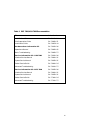
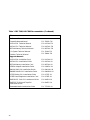
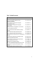
DWLMA XMI PIU
Installation Guide
Order Number EK–DWLMA–IN.001
This manual describes the installation of the XMI PIU into VAX
7000/10000 and DEC 7000/10000 AXP systems. Both system and expander cabinet installation are covered.
digital equipment corporation
maynard, massachusetts
First Printing, February 1993
The information in this document is subject to change without notice and should
not be construed as a commitment by Digital Equipment Corporation.
Digital Equipment Corporation assumes no responsibility for any errors that may
appear in this document.
The software, if any, described in this document is furnished under a license and
may be used or copied only in accordance with the terms of such license. No responsibility is assumed for the use or reliability of software or equipment that is
not supplied by Digital Equipment Corporation or its affiliated companies.
Copyright © 1993 by Digital Equipment Corporation.
All Rights Reserved.
Printed in U.S.A.
The following are trademarks of Digital Equipment Corporation:
Alpha AXP
AXP
DEC
DECchip
DEC LANcontroller
DECnet
DECUS
DWMVA
OpenVMS
ULTRIX
UNIBUS
VAX
VAXBI
VAXELN
VMScluster
XMI
The AXP logo
dT
OSF/1 is a registered trademark of the Open Software Foundation, Inc.
FCC NOTICE: The equipment described in this manual generates, uses, and may
emit radio frequency energy. The equipment has been type tested and found to
comply with the limits for a Class A computing device pursuant to Subpart J of
Part 15 of FCC Rules, which are designed to provide reasonable protection against
such radio frequency interference when operated in a commercial environment.
Operation of this equipment in a residential area may cause interference, in which
case the user at his own expense may be required to take measures to correct the
interference.
Contents
Preface ....................................................................................................... v
Chapter 1 Introduction
1.1
1.2
XMI PIU Placement and Rules ............................................. 1-2
XMI PIU Kit Contents ........................................................... 1-4
Chapter 2 Installation of the XMI PIU
2.1
2.2
2.3
2.4
2.5
Preparing the Cabinet .......................................................... 2-2
Installing the Card Cage Assembly ...................................... 2-4
Installing the 4 to 1 Cable ..................................................... 2-6
Installing the IOP Hose Cable .............................................. 2-8
Installing the DWLMA ........................................................ 2-10
Chapter 3 Verification
3.1
Restore Power and Check Self-Test Results ......................... 3-2
Appendix A Moving Hinges on the Bulkhead Door
A.1
Moving the Hinges of the Bulkhead Door ............................. A-2
Examples
3-1
Sample Self-Test Display ...................................................... 3-2
iii
Figures
1-1
1-2
2-1
2-2
2-3
2-4
2-5
2-6
3-1
A-1
System and Expander Cabinet XMI PIU Placement ........... 1-2
XMI Card Cage Assembly ...................................................... 1-4
Airflow Plate ........................................................................... 2-2
Installing the XMI PIU .......................................................... 2-4
Placement of the 4 to 1 Cable ................................................ 2-6
I/O Bulkhead Panel Designations ........................................ 2-7
IOP Cable Installation and Routing ..................................... 2-8
Installing the DWLMA ........................................................ 2-10
IOP Port Diagram .................................................................. 3-3
Bulkhead Doors on the XMI PIU Rear Cable Enclosure ..... A-2
Tables
1
2
1-1
iv
DEC 7000/VAX 7000 Documentation .................................... vii
Related Documents .................................................................. ix
DWLMA XMI PIU Kit Contents .......................................... 1-5
Preface
Intended Audience
This manual is written for Digital service engineers installing XMI plug-in
units in systems with an LSB as the system bus.
Document Structure
This manual uses a structured documentation design. Topics are organized into small sections for efficient on-line and printed reference. Each
topic begins with an abstract. You can quickly gain a comprehensive overview by reading only the abstracts. Next is an illustration or example,
which also provides quick reference. Last in the structure are descriptive
text and syntax definitions.
This manual has three chapters and one appendix, as follows:
•
Chapter 1, Introduction, describes the XMI PIU, its placement in
the system, and XMI configuration rules.
•
Chapter 2, Installation of the XMI PIU, describes the installation
procedure.
•
Chapter 3, Verification, describes the acceptance procedures.
•
Appendix A, Moving Hinges on the Bulkhead Door, describes
how to move the hinges on the I/O bulkhead door.
v
Conventions Used in This Document
Terminology. Unless specified otherwise, the use of "system" refers to
either a DEC 7000 AXP or VAX 7000 system. The DEC 7000 AXP systems
use the Alpha AXP architecture. References in text use DEC 7000 to refer
to DEC 7000 AXP systems.
Book titles. In text, if a book is cited without a product name, that book is
part of the hardware documentation. It is listed in Table 1 along with its
order number.
Icons. The icons shown below are used in illustrations for designating part
placement in the system described. A shaded area in the icon shows the
location of the component or part being discussed.
Front
Rear
Documentation Titles
Table 1 lists the books in the DEC 7000 and VAX 7000 documentation set.
Table 2 lists other documents that you may find useful.
vi
Table 1 DEC 7000/VAX 7000 Documentation
Title
Order Number
Installation Kit
EK–7000B–DK
Site Preparation Guide
EK–7000B–SP
Installation Guide
EK–700EB–IN
Hardware User Information Kit
EK–7001B–DK
Operations Manual
EK–7000B–OP
Basic Troubleshooting
EK–7000B–TS
Service Information Kit—VAX 7000
EK–7002A–DK
Platform Service Manual
EK–7000A–SV
System Service Manual
EK–7002B–SV
Pocket Service Guide
EK–7000A–PG
Advanced Troubleshooting
EK–7001A–TS
Service Information Kit—DEC 7000
EK–7002B–DK
Platform Service Manual
EK–7000A–SV
System Service Manual
EK–7002B–SV
Pocket Service Guide
EK–7700A–PG
Advanced Troubleshooting
EK–7701A–TS
vii
Table 1 DEC 7000/VAX 7000 Documentation (Continued)
Title
Order Number
Reference Manuals
Console Reference Manual
EK–70C0B–TM
KA7AA CPU Technical Manual
EK–KA7AA–TM
KN7AA CPU Technical Manual
EK–KN7AA–TM
MS7AA Memory Technical Manual
EK–MS7AA–TM
I/O System Technical Manual
EK–70I0A–TM
Platform Technical Manual
EK–7000A–TM
Upgrade Manuals
KA7AA CPU Installation Card
EK–KA7AA–IN
KN7AA CPU Installation Guide
EK–KN7AA–IN
MS7AA Memory Installation Card
EK–MS7AA–IN
KZMSA Adapter Installation Guide
EK–KXMSX–IN
DWLMA XMI PIU Installation Guide
EK–DWLMA–IN
DWMBB VAXBI PIU Installation Guide
EK–DWMBB–IN
H7237 Battery PIU Installation Guide
EK–H7237–IN
H7263 Power Regulator Installation Card
EK–H7263–IN
BA654 DSSI Disk PIU Installation Guide
EK–BA654–IN
BA655 SCSI Disk and Tape PIU
Installation Guide
EK–BA655–IN
Removable Media Installation Guide
EK–TFRRD–IN
viii
Table 2 Related Documents
Title
Order Number
General Site Preparation
Site Environmental Preparation Guide
EK–CSEPG–MA
System I/O Options
BA350 Modular Storage Shelf Subsystem
Configuration Guide
EK–BA350–CG
BA350 Modular Storage Shelf Subsystem
User’s Guide
EK–BA350–UG
BA350-LA Modular Storage Shelf User’s Guide
EK–350LA–UG
CIXCD Interface User Guide
EK–CIXCD–UG
DEC FDDIcontroller 400 Installation/Problem
Solving
EK–DEMFA–IP
DEC LANcontroller 400 Installation Guide
EK–DEMNA–IN
DEC LANcontroller 400 Technical Manual
EK–DEMNA–TM
DSSI VAXcluster Installation and Troubleshooting
Manual
EK–410AA–MG
InfoServer 150 Installation and Owner’s Guide
EK–INFSV–OM
KDM70 Controller User Guide
EK–KDM70–UG
KFMSA Module Installation and User Manual
EK–KFMSA–IM
KFMSA Module Service Guide
EK–KFMSA–SV
RRD42 Disc Drive Owner’s Manual
EK–RRD42–OM
RF Series Integrated Storage Element User Guide
EK–RF72D–UG
Tx85 Series Cartridge Tape Subsystem Owner’s
Manual
EK–OTF85–OM
TLZ06 Cassette Tape Drive Owner’s Manual
EK–TLZ06–OM
ix
Table 2 Related Documents (Continued)
Title
Order Number
Operating System Manuals
Alpha Architecture Reference Manual
EY–L520E–DP
DEC OSF/1 Guide to System Administration
AA–PJU7A–TE
DECnet for OpenVMS Network Management Utilities
AA–PQYAA–TK
Guide to Installing DEC OSF/1
AA–PS2DA–TE
OpenVMS Alpha Version 1.0 Upgrade and
Installation Manual
AA–PQYSA–TE
VMS Upgrade and Installation Supplement:
VAX 7000–600 and VAX 10000–600 Series
AA–PRAHA–TE
VMS Network Control Program Manual
AA–LA50A–TE
VMSclusters and Networking
HSC Installation Manual
EK–HSCMN–IN
SC008 Star Coupler User’s Guide
EK–SC008–UG
VAX Volume Shadowing Manual
AA–PBTVA–TE
Peripherals
x
Installing and Using the VT420 Video Terminal
EK–VT420–UG
LA75 Companion Printer Installation and User Guide
EK–LA75X–UG
Chapter 1
Introduction
The XMI plug-in unit (PIU) is an I/O subsystem bus that can be installed
in an LSB system cabinet or an LSB expander cabinet. This chapter describes the placement of the XMI PIU in both the system and expander
cabinets and the contents of the two kits. It also lists XMI configuration
rules. Sections include:
•
XMI PIU Placement and Rules
•
XMI PIU Kit Contents
Introduction 1-1
1.1 XMI PIU Placement and Rules
The XMI PIU takes up two of four quadrants of space in the bottom of either a system or expander cabinet. The XMI card cage is
installed in either the right or left front quadrant and extends into
the rear quadrant.
Figure 1-1
System and Expander Cabinet XMI PIU Placement
Rear
System
Rear
Expander
Quadrant 2
Quadrant 4
4 2
4 2
Quadrant 1
Quadrant 3
1 3
1 3
Front
System
Front
Expander
BXB-0044M-93
1-2 Introduction
Figure 1-1 shows the quadrant designation for system and expander cabinets. XMI PIUs are installed in the bottom of either cabinet with the card
cages and power regulators installed in the front. The XMI PIU requires
two quadrants of space: quadrants 1 and 2 if the card cage is installed on
the left, and quadrants 3 and 4 if it is installed on the right when you face
either cabinet. From the front of either cabinet the XMI PIU must be to
the left of a VAXBI PIU if one is installed.
The following rules apply:
1.
XMI PIUs in cabinets
a. XMI PIUs are placed in the bottom of cabinets.
b. A maximum of two XMI PIUs can be placed in a cabinet.
c. A maximum of four XMI PIUs can be placed in a system.
2.
XMI PIU Configuration Rules
a. Each XMI PIU occupies two of the bottom quadrants: 1 and 2 or 3
and 4. The XMI PIU occupies quadrants 1 and 2 when a VAXBI
PIU is installed.
b. The XMI bulkhead has 20 dual I/O panels. One is used for the I/O
cable from the IOP.
3.
XMI Configuration Rules
a. Of the 14 slots on the XMI, 12 are available for I/O devices. Two
slots are reserved; slot 7, for the T2030-YA, the clock module, and
slot 8, for the T2028-AA, the DWLMA module.
b. The first option on an XMI must reside either in slot 1 or slot 14 to
terminate the bus. If the option is a two-module option, the module with the XMI corner must be in slot 1 or 14.
c. If the cabinet has a VAXBI PIU, the T2018 module (XBIA+) must
reside in slot 1 of the XMI backplane.
Introduction 1-3
1.2 XMI PIU Kit Contents
The DWLMA XMI PIU option has two variants: one for a system
cabinet and the other for an expander cabinet. The only difference between the two kits is the length of the cable that goes from
the IOP in the system cabinet to the I/O bulkhead. Figure 1-2
shows the XMI PIU assembly.
Figure 1-2
XMI Card Cage Assembly
XMI
Card Cage
Rear Cable
Enclosure
Clock Module
T2030-YA
BXB-0368C-93
1-4 Introduction
The contents of the two kits follows:
•
The XMI PIU card cage assembly consists of two major pieces:
— The card cage itself with the power regulators which plugs into
either cabinet from the front. The clock module is already installed
in the card cage.
— The rear cable enclosure, consisting of the enclosure and the bulkhead panel door that plugs into either cabinet from the back. Figure 1-2 shows the two pieces. (See Section 2.2 for installation.)
•
The DWLMA adapter module is placed in slot 8 of the XMI. (See Section 2.5 for installation.)
•
The 4 to 1 cable is placed between the I/O bulkhead and the XMI
backplane. (See Section 2.3 for installation.)
•
Either the 4.5 foot or 10 foot cable connects the IOP module and the
I/O bulkhead. (See Section 2.4 for installation.)
Table 1-1
DWLMA XMI PIU Kit Contents
Part Number
Quantity
Description
BA651-AA
1
XMI PIU card cage assembly, clock module (T2030-YA), and the DC to DC power
regulators
T2028-AA
1
DWLMA module
17-03061-01
1
4 to 1 cable with bulkhead
17-03085-02
*
4.5 foot hose cable for the system cabinet
(DWLMA-AA variant)
17-03085-01
*
10 foot hose cable for the expander cabinet (DWLMA-BA variant)
EK-DWLMA-IN
1
This installation guide
* One IOP hose cable is present. The 4.5 foot cable is in the system cabinet kit, and the
10 foot cable is in the expander cabinet kit.
Introduction 1-5
Chapter 2
Installation of the XMI PIU
Five tasks are necessary to install an XMI PIU. They are:
•
Preparing the Cabinet
•
Installing the Card Cage Assembly
•
Installing the 4 to 1 Cable
•
Installing the IOP Hose Cable
•
Installing the DWLMA
Installation of the XMI PIU 2-1
2.1 Preparing the Cabinet
After you determine the XMI PIU quadrant location, you must remove the airflow plates located below the blower and above the
quadrants you will be using.
Figure 2-1
Airflow Plate
7
Front
Rear
BXB-0412B-93
2-2 Installation of the XMI PIU
Take the following steps to prepare the system:
1.
Perform an orderly shutdown of the system.
2.
Turn the keyswitch to Disable.
3.
Determine which quadrants will house the XMI PIU (in the system or
expander cabinet). See Section 1.1 for placement rules.
4.
Open the front and rear doors of the cabinet. If you are installing the
XMI PIU in an expander cabinet, you will need access to the rear of
the system cabinet also.
5.
Shut the circuit breaker on the AC power box off by pushing down on
the breaker. The AC power box is above the blower and to the left in
both cabinets.
6.
If you are installing the PIU in an expander cabinet, drop the skirts
below the rear doors of both cabinets.
7.
Remove the two airflow plates from the front and rear of the cabinet
(see Figure 2-1). These slide out of the cabinet and should be labeled
and saved. (If the PIU is removed, these plates must be replaced to
maintain proper airflow in the cabinet.)
8.
The bulkhead door on the rear cable enclosure of the XMI PIU comes
hinged on the left. If the XMI PIU is placed in the cabinet on the left
when viewed from the rear (quadrants 3 and 4), the door should be
hinged on the right. If you need to change the hinges, do that now,
following the procedure in Appendix A.
Installation of the XMI PIU 2-3
2.2 Installing the Card Cage Assembly
The BA651-AA card cage assembly consists of two parts: the card
cage assembly with the clock module and power regulators, and
the rear cable enclosure. First install the card cage assembly and
then the rear enclosure.
Figure 2-2
Installing the XMI PIU
Front
Rear
3
4
BXB-0405D-93
2-4 Installation of the XMI PIU
To install the XMI PIU:
NOTE: Before installing the PIU, inspect the electromagnetic interference
(EMI) gaskets; return the option if they are damaged.
1.
Ground yourself to the cabinet with the antistatic wrist strap from the
Electrical Safety Kit.
2.
Place the XMI card cage half into the cabinet by lining up the rollers
on the PIU with the slides in the cabinet. Now push the card cage into
the cabinet until it seats.
3.
Line up and only slightly tighten the two captive screws (slotted) at
the top of the PIU, 3 in Figure 2-2.
4.
Install the two Phillips head screws at the bottom of the card cage securing the PIU to the cabinet, 4 in Figure 2-2. Tighten the two captive screws mentioned in step 3 to 27 inch-pounds.
5.
Be sure the I/O bulkhead door opens in the correct direction before
proceeding to step 6. See Section 2.1, step 8.
6.
At the back of the cabinet, install the rear cable enclosure lining up
the rollers on the PIU with the slides in the cabinet.
7.
Line up and only slightly tighten the two captive screws (slotted) at
the top of the enclosure.
8.
Install the two Phillips head screws at the bottom of the cable enclosure securing the back of the PIU to the cabinet. Tighten the two captive screws mentioned in step 7 to 27 inch-pounds. Tightening these
screws compresses the EMI gaskets between the two halves.
Installation of the XMI PIU 2-5
2.3 Installing the 4 to 1 Cable
The 4 to 1 cable, part number 17-03061-01, is installed between the
XMI backplane and the I/O bulkhead.
Figure 2-3
Placement of the 4 to 1 Cable
D
E
Rear
Slot 1
2
3
4
5
6
DL
EL
7
8
9 10 11 12 13 14
D1 D2
E1 E2
DR
ER
8
BXB-0444-93
2-6 Installation of the XMI PIU
The 4 to 1 cable is labeled for easy, correct installation. The bulkhead end
of the cable is easily identified by the bulkhead plate and the receptacle for
the IOP cable. The XMI backplane end has four connectors labeled DL,
DR, EL, and ER.
To install the cable:
1.
Remove the plastic shield from the XMI backplane.
2.
Figure 2-4 shows the I/O bulkhead door. If the XMI PIU is installed
on the left, the bulkhead plate of the 4 to 1 cable goes in A5; if it is on
the right, the bulkhead plate goes in A1. Select and remove the correct panel from the I/O bulkhead door.
3.
The IOP connector is offset on the bulkhead plate. When the plate is
installed in a system cabinet, the connector is to the left of center.
When the plate is installed in an expander cabinet, the connector is
right of center. Install the bulkhead end of the 4 to 1 cable in the
bulkhead door by passing the cables through the door and secure by
using the two screws removed from the plate in step 2.
4.
The DWLMA adapter goes in slot 8. Slot 7 is used for the clock module and has no connectors. Slot 8 is to its right on the XMI backplane.
See Figure 2-3.
5.
Install the cable marked DL into the left receptacle of row D, slot 8.
6.
Install the cable marked DR into the right receptacle of row D, slot 8.
7.
Install the cable marked EL into the left receptacle of row E, slot 8.
8.
Install the cable marked ER into the right receptacle of row E, slot 8.
9.
Replace the plastic shield.
Figure 2-4
I/O Bulkhead Panel Designations
D
C
Rear
B
A
12
34 5
12
34 5
BXB-0443-93
Installation of the XMI PIU 2-7
2.4 Installing the IOP Hose Cable
The IOP hose cable, part number 17-03085-01 or 17-03085-02, connects the IOP in the system cabinet and the I/O bulkhead. The
longer hose, the -01 variation, is used when the PIU is installed in
an expander cabinet. Figure 2-5 shows the IOP cable routing for
both system and expander cabinets.
Figure 2-5
IOP Cable Installation and Routing
Rear
Expander
Rear
System
IOP
Module
2
Expander
Cabinet I/OCable
1
System
Cabinet I/O Cable
BXB-0437-93
2-8 Installation of the XMI PIU
The IOP cable is labeled for easy and correct installation. The IOP end is
labeled IOP, and the bulkhead end is labeled PIU.
To install the cable:
1.
Plug the IOP end of the cable into one of the IOP module connectors
and secure the end of the cable.
2.
Route the cable according to Figure 2-5. 1 shows the routing for the
cable in a system cabinet, and 2 shows the routing for a cable to an
expander cabinet.
3.
Plug the PIU end of the cable into the bulkhead connector end of the 4
to 1 cable you just installed and secure the end of the cable.
4.
Once the cable has been installed, replace the skirt at the back of the
cabinet.
Installation of the XMI PIU 2-9
2.5 Installing the DWLMA
The DWLMA is installed in slot 8 of the XMI card cage. The XMI
PIU comes with the clock card already installed in slot 7. Slot 8 is
to the left of slot 7 when looking into the card cage.
Figure 2-6
Installing the DWLMA
XMI Card Cage
Front
DWLMA
Module
Clock
Module
*
14 13 12 11 10 9
8 7 6 5 4
*
3 2 1
*A module is required in slot 1 or 14 to terminate bus.
BXB-0438-93
2-10 Installation of the XMI PIU
To install the DWLMA:
1.
At the front of the cabinet, ground yourself using the ESD strap.
2.
Install the DWLMA, the T2028-AA module, in slot 8. Slot 8 is the slot
to the left of the clock module already installed.
Before installing and cabling all sorts of I/O options, you might want to
verify the PIU installation by proceeding to the Verification chapter.
Installation of the XMI PIU 2-11
Chapter 3
Verification
This chapter describes the acceptance procedure and troubleshooting
guidelines for the XMI PIU. See the Advanced Troubleshooting manual for
more information. Sections include:
•
Restore Power and Check Self-Test Results
Verification 3-1
3.1 Restore Power and Check Self-Test Results
Install a supported XMI option with an XMI corner in either slot 1
or 14 to terminate the XMI bus. Restore power to the system and
check the self-test results to see that the XMI PIU is functioning
properly.
Example 3-1
F
Sample Self-Test Display
E
D
C
B
A
9
8
A
o
.
o
.
+
.
7
M
+
.
+
.
+
.
6
.
.
.
.
.
.
.
5
.
.
.
.
.
.
.
4
.
.
.
.
.
.
.
3
.
.
.
.
.
.
.
2
.
.
.
.
.
.
.
1
P
+
E
+
E
+
E
+
.
.
.
.
.
.
.
.
.
.
.
.
.
.
.
.
.
.
.
.
.
.
.
+
.
.
.
.
.
.
.
.
.
.
.
.
.
.
.
.
.
.
.
+
.
.
.
.
.
.
.
.
.
.
.
. A0 .
. 128 .
.
.
.
.
.
.
.
.
.
.
Firmware Rev =
P00>>>
3-2 Verification
V1.0-1625
SROM Rev =
V1.0-0
0
P
+
B
+
B
+
B
NODE #
TYP
ST1
BPD
ST2
BPD
ST3
BPD
C0 XMI +
C1 XMI C2
C3
.
.
1
2
ILV
128MB
SYS SN =
GAO1234567
BXB-0030Q-93
To verify that the XMI PIU is functioning properly:
1.
Insert a supported XMI option into either slot 1 or 14 to terminate the
XMI bus. The module you install must have an XMI corner on it.
2.
Power on the system and examine the self-test results to determine
whether the XMI PIU passes. Example 3-1 shows sample self-test results. Two XMIs are shown in the example.
The + at the end of the line marked
to the C0 hose is functioning.
1
shows that the XMI connected
The − at the end of the line marked
to the C1 hose is not functioning.
2
shows that the XMI connected
Lines C0, C1, C2, and C3 correspond to IOP ports (see Figure 3-1).
In Example 3-1 the XMI connected to IOP port C1 is failing. If the C
line indicates a problem, check all the cabling and retest. If the problem continues, follow the troubleshooting procedures in your system’s
Advanced Troubleshooting manual.
To verify that each slot in the backplane works, do the following:
1.
Install a "known good module" in the slot you wish to test.
2.
Power on the system.
3.
Examine the self-test results to determine whether the slot is working.
4.
Repeat steps 1 through 3 for each slot.
If a slot fails, return the option. If the XMI PIU passes verification, continue with the installation of XMI options.
Figure 3-1
IOP Port Diagram
C0
C1
C2
Rear
C3
BXB-0623-93
Verification 3-3
Appendix A
Moving Hinges on the Bulkhead
Door
The XMI plug-in unit comes with the rear bulkhead door hinged at the left.
The door opens properly when the enclosure is in the rear right quadrant
(Q2). When the enclosure is in the rear left quadrant (Q4), the door should
be hinged on the right so that the hose is moved as little as possible when
the door is opened. This appendix describes how to change the hinges.
Moving Hinges on the Bulkhead Door A-1
A.1 Moving the Hinges of the Bulkhead Door
In addition to moving the hinges from one side of the bulkhead
door to the other, the EMI finger stock and the plunger fasteners
must be moved.
Figure A-1
Bulkhead Doors on the XMI PIU Rear Cable
Enclosure
Plunger
fastener
Hinges
Plunger
fastener
Rear
Plunger
fastener
Hinges
Plunger
fastener
BXB-0446-92
A-2
Moving Hinges on the Bulkhead Door
Figure A-1 shows two bulkhead doors; one hinged left and the other hinged
right. Follow these steps when moving the hinges on the doors from one
side to the other. The steps assume the door is hinged left.
1.
Remove the door by unscrewing the shoulder bolt hinges at the top
and bottom. Note that the nylon washers are between the enclosure
and the door.
2.
Move the plastic spacer on the bottom right flange of the enclosure to
the bottom left of the enclosure (where the bottom hinge used to be).
3.
Remove the EMI finger stock from the top flange on the enclosure.
4.
Using two 3/8 inch wrenches, remove the plunger fastener on the top
flange of the enclosure and reinstall it one hole to the left of its original location. Put the plunger in its hold open position to secure the
"top" wrench and hold the "nut" under the flange with the other
wrench and remove or tighten.
5.
Reinstall the EMI finger stock.
6.
Remove the EMI finger stock from the bottom of the door.
7.
Using two 3/8 inch wrenches remove the plunger fastener on the bottom of the door and reinstall it one hole to the left of its original location. Put the plunger in its hold open position to secure the "top"
wrench and hold the "nut" under the flange with the other wrench and
remove or tighten.
8.
Reinstall the EMI finger stock on the door.
9.
Press the door into the enclosure allowing the EMI finger stock to hold
it in place.
10. Reinstall the shoulder bolt hinges on the right. Be sure to place the
nylon washers between the enclosure and the door.
Moving Hinges on the Bulkhead Door A-3
Index
A
Airflow plate removal, 2-2
C
Configuration rules, 1-3
I
Installing
card cage assembly, 2-4
DWMLA module, 2-10
IOP cable, 2-8
rear cable enclosure, 2-4
4 to 1 cable, 2-6
I/O port diagram, 3-4
S
Self-test results, 3-2
X
XMI configuration rules, 1-3
XMI PIU
kit contents, 1-4
placement, 1-2
XMI termination requirement, 1-3
Index-1