1
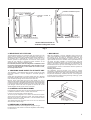
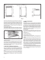
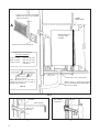
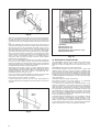
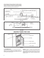
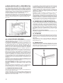
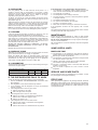
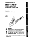
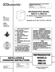
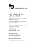
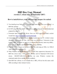
OPERATING AND INSTALLATION INSTRUCTIONS
FOR DOMETIC REFRIGERATORS
TYPE: A30-80K
MODEL RM 123E
(Bottled Gas and 12/230 Volt Operation)
MODEL RM 122F
(Bottled GAS AND 12 Volt Operation)
207.4495.02
0402
IMPORTANT USER INFORMATION
It most important that this instruction book should be retained with the appliance for future reference. Should the appliance be sold or
transferred to another owner, always ensure that the book is supplied with the appliance in order that the new owner can be acquainted with
the functionning of the appliance and the relevant warnings.
These warnings are provided in the interest of safety. You must read them carefully before installing or using the appliance.
This product is designed to be operated by adults. Children
should not be allowed to tamper with the controls or play with the
product.
Any electrical work required to install this appliance should be
carried out by a qualified electrician.
This product should be serviced by an authorised Service
Engineer and only genuine spare parts should be used.
It is dangerous to alter the specifications or modify this product in
any way.
Care must be taken to ensure that the appliance does not stand
on the electrical supply cable.
These refrigerators are designed to be used specifically for the
storage of edible foodstuffs only.
There are workings parts in this product which heat up. Always
ensure that there is adequate ventilation as a failure to do this will
result in component failure and possible food loss. See
installation instruction.
Parts which heat up should not be exposed. Wherever possible
the back of the product should be close to a wall but leaving the
required distance for ventilation as stated in the installation
instructions.
Before defrosting, cleaning or maintenance work is carried out, be
sure to switch off the appliance and unplug it.
The ice box in this appliance contains tubes through which the
refrigerant passes. If these are punctured this would cause
substantial damage and result in food loss. DO NOT USE SHARP
INSTRUMENTS to scrape off frost or ice. Under no
circumstances should solid ice be forced off the ice box. Solid ice
should be allowed to thaw when defrosting the appliance. See
defrost instructions.
The appliance should be left for 2 hours after installation
before it is turned on in order to allow refrigerant to settle,
unless it is of the absorption type in which case it can be
turned on immediately.
This appliance is heavy. Care should be taken when moving
it.
Ice lollies can cause frost burns if consumed straight from the
freezer.
Frozen food must not be refrozen once it has thawed out.
Manufacturers' food storage recommendations should be
strictly adhered to. Refer to relevant instructions.
Do not place carbonated or fizzy drinks in the freezer as it
creates pressure on the container which may cause it to
explode resulting in damage to the appliance.
Under no circumstances should you attempt to repair the
appliance yourself. Repairs carried out by inexperienced
persons may cause injury or more serious malfunctioning.
Refer to your local Service Centre and always insist on
genuine spare parts.
GENERAL GUIDE TO FITTING ANY PLUG
Ensure the lengths of wire inside the plug are prepared
correctly.
Connections should be firmly made after all conductor strands
are entered into the terminal posts.
When preparing the cable ends take care not to damage the
outer sheath, or the insulation surrounding the inner
conductors.
Tighten all screws.
Replace the top cover of the plug and secure.
INSTRUCTIONS FOR INSTALLATION
1. INTRODUCTION
Before starting to install the refrigerator, please read these
instructions carefully in order to obtain a thorough understanding of
what is required.
When operating, heat is emitted from parts of the cooling unit at the
rear and this has to be carried away by air circulating freely over the
back of the refrigerator. To ensure sufficient air circulation for
satisfactory operation. It is essential that the clearances called
for in these instructions are not reduced in any way otherwise
cooling performance will be impaired. Providing the refrigerator is
installed in accordance with these instructions, it should operate
satisfactorily in ambient temperatures up to 32°C (90°F), with some
measure of cooling up to about 35°C (95°F).
It is recommended that the refrigerator is installed by the caravan
manufacturer, the supplier or another qualified person Owners who
are competent to carry out the work themselves can do so, but, for
the sake of safety, they must take particular care in making the gas
connections, checking for leaks, and installing the electrical wiring
and fittings. All relevant regulations concerning such installations
must be complied with.
Many caravans are already provided with a recess, usually in the
form of a cupboard which has been specially designed so that it can
be adapted, by removal of its door and shelves, to house a
refrigerator. Some caravan manufacturers have also devosed kits of
parts to aid installation of refrigerators in their particular caravans.
A ventilator for fitting above the door as shown in fig. 4 is supplied
with the refrigerator. The connection pipe, gas cock, and connectors
are not supplied as the sizes of these may vary to suit particular
installations. The appropriate parts should, however, be readily
available from the refrigerator supplier or an Agent dealing in gas
fittings 9see note in item 11).
The refrigerator weighs approximately 14,5 kg (321b) and the surface
on which it is installed must be capable of carrying this weight, plus
that of the food, satisfactorily.
All surfaces above and adjacent to the flue outlet, and beside
and below the burner housing should be of, or covered with,
metal or other non-flammable material.
2
IMPORTANT: On motorised vehicles, the refrigerator must be
installed well away from fuel tanks, fuel filling inlets, pipes leading
from inlets to fuel tanks, and fuel tank breathers.
WARNING:
Because of the hazards associated with the use of continuous
operating bottled-gas appliances with open-flame burners in
difficult-to-ventilate confined spaces, and other considerations,
Dometic RT do not recommend the installation of their bottled-gas
caravan refrigerators on boats, and refrigerators so installed will
not be covered by the Company's guarantee.
If, however, a boat installation is planned for the refrigerator,
reference should be made to British Standard 5482 Part 3, 1979
and to the Thames Water Authority "Launch Digest" and "Launch
Specification".
Also, current Guide Lines published by local Water Authorities, or
the Ship and Boat Builders' National Federation.
It should be noted that special Marine Refrigerators are available
from Electrolux for use on boats.
2. VENTILATION
The refrigerator will always be built into a recess but to enable the
unit to operate efficiently, it is essential that air is allowed to
circulate freely over the cooling unit at the back to carry away the
heat generated during the cooling process 9see fig. 10. The
minimum free spaces called for under, behind and over the
cabinet must not, therefore, be reduced in any way. The more
space provided, particulary behind and over the cabinet, the
better the performance you can expect from the cooling unit.
ventilator located at top rear.
Flue Outlet
Flue Outlet
ventilator located at
top front
(a)
(b)
Arrows indicate air-flow to
ventilate cooling unit at rear
Fig. 1
3. IMPORTANCE OF LEVELLING
7. BUILDING-IN
The downward circulation of refrigerant within the cooling unit is by
gravity and the refrigerator has to be reasonably level, when it is
stationary, for the cooling unit to operate properly. If the refrigerator is
left operating with a sustained list in excess of about 3º in any
direction, pockets of liquid refrigerant can collect at various points
within the unit impairing or preventing normal circulation of the
refrigerant vapour until level conditions return.
It is essential, therefore, that the refrigerator is installed so that
the ice-tray shelf inside the refrigerator is level in relation to the
caravan, in both directions, so that when the caravan is level,
the ice-tray shlef is level.
While the refrigerator is built-in, adequate space must be left
under, over and behind it to allow a sufficient circulation of air over
the cooling unit at the back for satisfactory operation. The
recommended method of building-in is shown in fig. 5, with the
upper ventilator at the front. However, where space limitations do
not permit the upper ventilator to be fitted at the front, the
alternative arrangement shown in fig. 6 may be adopted and the
height of the recess reduced accordingly. A work-surface can
then be fitted over the top front of the refrigerator, but it must not
over-hang the door where it could interfere with the operation of
the travel catch.
Securing in the Recess
The refrigerator must be secured in the recess to prevent
movement. A suggested method of securing is by means of metal
brackets about 20 mm (3/4") wide, (which should be made to suit
the particular installation), screwed to the rear of the refrigerator
by means of the two existing cooling unit fixing screws (fig. 2) and
to the rear wall of the caravan
4. CHANGING DOOR HINGES TO OPPOSITE SIDE
The refrigerator is manufactured with the door hinged on the right
hand side, however, it can be changed to left hand opening if
required.
Gently place the refrigerator on its back (taking care not to damage
the burner assembly0, pull off the gas control knob, then remove the
lower ventilator by taking out the screws from each end.
Remove upper hinge blade and travel catch blade from top of
cabinet. Fit the upper hinge blade and travel catch blade to their new
positions on the top of the cabinet and transfer the lower hinge blade
to the opposite side. Refit the ventilator by means of the screws, then
push the gas control knob onto its spindle so that the flat on the
spindle engages the flat in the recess of the knob.
5. CHANGING OUTER DOOR PANEL
If required, the outer door panel can be removed and replaced by one
of a different material or colour to match other fitments.
I can be of rust proof metal or plastic laminate.
To do this lay the refrigerator on its back, and remove the bottom
section of the door frame held by 3 screws. The existing panel can
then be slid out and a new panel slid in, and the bottom section
refitted to retain the new panel.
The replacement panel should be from 0,5 mm to 3 mm thick, and
350 mm wide x 485 mm high.
6. DIMENSIONS OF REFRIGERATOR
Fig. 2
The exterior dimensions of the refrigerator are given in fig. 3.
For dimensions of the recess to house the refrigerator when buildingin, refer to item 7.
3
300 mm
(11 13/16")
100 mm
(4")
15/ ")
16
380 mm (15")
400 mm
(15 13/16")
659 mm (25
510 mm (20 1/16")
73 mm
(2 7/8")
439 mm (17 5/16")
39 mm
( 1 1/2")
Fig. 3
Alternatively, wooden battens may be screwed to the sides of the
recess, from front to back, bearing down on the top of the cabinet to
hold it firmly, as shown at A, fig. 4. Whichever method is used, it must
be possible to remove the refrigerator easily for subsequent servicing
purposes. The brackets or battens must be in a position where they
will not restrict the air circulation over the cooling unit; they must not
be positioned across the cabinet over the fins of the condenser of the
cooling unit at the rear, otherwise air-flow will be impaired and
performance affected.
Fitting the Upper Ventilator
To fit the upper ventilator, screw a block of wood approx. 25 mm (1")
square x 66 mm (2 5/8) long. to each side of the recess, 16 mm (5/8")
back from the front edge, as shown at B, fig. 4. Secure the ventilator
to the blocks with a screw through the hole provided at each end.
B
A
Fig. 4
Additionnal Ventilator
To reduce the amount of heat entering the caravan, particularly when
used in warner climates, an additionnal ventilator (A, fig. 5), may be
fitted in the wall of the vehicle, preferably above the level of the top
of the refrigerator. (The exterior flue venting kit must still be used).
All surfaces above and adjacent to the flue outlet, and beside and
below the burner housing should be of, or protected by, metal or
other inflammable material.
8. VENT HOLE UNDER REFRIGERATOR
A ventilation hole of not less than 13 cm2 (2in2) effective area (40
mm or 1 5/8" diameter) must be provided in the floor below the
refrigerator as shown in fig. 5. The hole should lead directly to the
outside air through the floor or wall so that, in the event of a gas leak,
it would provide an escape outlet for the heavier-than air gas. It
should not be too close to the burner where draught could affect the
flame.
On mobile installations, the vent hole should be shielded against
entry of mud etc., by a deflector as shown in fig. 5a, fitted underneath
with its "closed" end facing the front of the vehicle. The deflector
should be made from a suitable piece of metal, to suit the particular
installation.
4
9. FLUE ARRANGEMENT
Flue Baffle
The flue baffle (4, fig. 10) must be in position in the central tube
of the boiler, suspended on its support wire so that the lower end
of the baffle is 75 mm (3") above the bottom of the central tube
over the burner. The top end of the baffle support wire is bent into
the shape of an "O" and rests horizontally on the tp of the central
tube. The baffle is correctly positioned during the manufacture
ans should not become displaced during normal use. If the flue
baffle is missins or is incorrectly located, the cooling unit will not
operate properly on gas. Any strapping tape used to retain the
baffle support wire to the top of the boiler casing during transit
should be removed before installation.
Flue Venting Kit
The flue gasses must be vented directly to the outside air. Only
the flue venting kit (supplied with the refrigerator in the United
Kingdom) is recommended for this purpose. It consists of the
following parts:
Flue Top Complete-G
Flue Outlet Cover Plate-B
Exhaust Gas Pipe Complete-F
Screw-sELF tAPPING. nO. 6 X 1/4in-H
The flue top (G) is in the form of a lazy "T" and incorporates an
air-break to minimise the possibility of flame extinction due to
draughts.
Leading from the flue-top, the extension tube (F) has to pass
through the wall of the vehicle to direct the flue gasses to the
outside. Care must be taken in determining the positions of the
centres of the holes in the inner and outer skins of the caravan
wall to accept the extension tube. As the amount of space
between the back of the refrigerator and the inside wall og the
vehicle as well as the thickness of the wall, may vary for each
type of caravan, it is not possible to give actual dimensions
therefore each case must be considered carefully before starting
to make the opening. Take particular care to ensure that the angle
is correct so that when in position, the extension tube will line up
accurately with the sloping part of the flue-top.
The opening mus be large enough to allow the insertion of a layer
of non-combustible material around the extension tube as shown
in fig. 7, but the opening in the outer skin must not exceed 70 mm
(2 3/4") in diameter, otherwise the flange on the flue outlet may
not cover it completely.
Leave as much space as possible
between the side of the ventilator
and the flue outlet.
76 mm
(3")
UPPER
VENTILATOR
Wooden blocks for
securing upper
ventilator.
662 mm
(26 1/16")
Outer Cover of Flue Venting Kit.
DIMENSIONS OF RECESS
(with front ventilation)
662 mm (26 1/16")
Width of recess -
383 mm (15 1/16")
Depth of recess -
400 mm (15 3/4")
(minimum).
76 mm
(3")
Height of recess -
400 mm
(15 3/4") min
VENT HOLE 40 mm (1 5/8") Dia. to
outside air, through floor or wall on
opposite side to burner.
Vent hole in floor (see fig. 5a).
Where recess is above floor height,
the vent should be extended through a
pipe to the outside.
FIG. 5a
Fig. 5
76 mm
(3")
Ventilator
Work surface
Soft selaing
compound
Non-combustible
material
100 mm (4")
minimum
Fig. 6
5
Fig. 7
F
G
3
2
1
H
4
Fig. 8
When the opening has been made in the caravan wall, the extension
tube (F) may need to be shortened to suit the particular installation.
To determine if this is necessary, fit the flue top (G) to the top of the
central tube of the boiler casing and secure it by means of the screw
(H).
Place the refrigerator into position, then insert the free end of the
extension tube through the wall of the caravan and over the outlet of
the flue-top as far as it will go. Measure the length 'X' (fig. 9) of any
tube protruding from the outside. Transfer this measurement to the
other end of the tube as shown at 'Y' (fig. 9) and cut at right angles
through the tube at this point to shorten the tube to the correct length.
Note 1. If the caravan wall is not vertical or is contoured in the vicinity
of the flue outlet, it may be necessary to make a packing piece from
metal or other non-combustible material, of a suitable shape to
ensure that, when in position, the plate on the flue outlet is parallel
with the back of the refrigerator.
Note 2. It is not advisable to lengthen the flue venting arrangement
for more than a short distance as this may result in the flue gasses
becoming prematurely cooled and water vapour (which is produced
during the natural process of combustion) condensing in the flue and
running back into the boiler insulation and burner.
At this stage, refer to items 10 and 11 in order to prepare for the 12V
and bottled gas connections. When these have been made, before
finally positioning the flue extension tube (F), ensure that the portion
passing through the wall of the vehicle is surrounded by noncombustible material as shown in fig. 7.
Use a soft sealing compound between the flange of the flue outlet
and the wall of the caravan to prevent ingress of rain water.
Fit the outer cover (B) by means of 4 screws.
It will be necessary to remove the outer cover and withdraw the
extension tube before the refrigerator can be moved out of position at
any time.
CUT
HERE
Fig. 9
6
5
1.Flue Baffle.
2.Therminal block 12 V.
3.Heating element 12 V.
4.Therminal block 230 V (under the cover).
5.Heating element 230 V.
Fig. 10
10. ELECTRICAL INSTALLATION
On model RM123, the boiler of the cooling unit is fitted with two
separate heaters, rated at 75W, for use on 230V a.c. mains
electricity, and the 12V battery in the car when the caravan is on
tow.
Model RM122 does not have a 230V heater fitted.
The electrical installation must be carried out in a proper and
durable manner, taking into account all relevant regulations and
codes of practice. For mains voltage operation, it is important that
the circuit to and in the caravan is effectively earthed. All mains
voltage wiring in the caravan must be installed in accordance with
current IEE Regulations including the use of an outlet and coupler
to BS 4343/CEE 17.
a) Wiring for Electronic Igniter (where fitted)
The electronic igniter for the gas burner is for permanent
connection to a 12V d.c. supply, e.g car battery.
In a motor-van, the igniter can be connected directly to the
vehicle's main battery or to an existing 12V circuit in the vehicle
which will remain on continuously and will not be switched off
when the engine is switched off. In a caravan, in order to maintain
the supply when the towing vehicle is unhitched, the igniter must
be connected to an auxiliary battery in the caravan. The current
drain of the igniter is negligible therefore the battery can be one
that is also used for operating other equipment in the caravan
such as the water pump, lights, etc.
Connect the igniter terminal block (fig. 11) to the battery, ensuring
that correct polarity is observed-the terminals marked' + and'-'
must be connected to the similarly marked terminals of the
battery. The wire used for connecting should be at least 0,5 mm2
in cross-sectional area and a 0.5 or 1.0 amp inline fuse should be
fitted in the feed wire, as near to the battery as possible.
Burner housing
Bottom of refrigerator
Igniter
terminal
block
Housing for
electronic
components
Iigniter
switch
View of bottom of refrigerator showing electronic
igniter layout
Fig. 11
b) Mains Voltage Connection
For connection to a 230V electricity-supply, the refrigerator has a 3core mains lead which is intended for connection to a oroperly
earthed plug and socket outlet. The socket outlet should be fitted in
the caravan in a position readily accessible to the user, within reach
of the mains lead. In the United Kingdom, the plug and socket outlet
should be of the non-reversible type.
IMPORTANT: The wires in the mains lead of this appliance are
coloured in accordance with the following code:
GREEN AND YELLOW
=
EARTH.
BLUE
=
NEUTRAL.
BROWN
=
LIVE.
As the colours of the wires may
not correspond with the
coloured markings identifying
the terminals in your plug, in
the United Kingdom, proceed
as follows:
Green and Yellow, 3 AMP
FUSE, E, N, Lrown, Coro
Clamp.
The wire which is coloured
GREEN AND YELLOW must
be connected to the terminal in
the plug which is marked with
the letter E or by the earth
symbol
or coloured green
or green and yellow.
The wire which is coloured BLUE must be connected to the terminal
which is marked with the letter N or coloured black.
The wire which is coloured BROWN must be connected to the
terminal which is marked with the letter L or coloured red.
WARNING-THIS APPLIANCE MUST BE EARTHED
In the United Kingdom, the plug or circuit to the refrigerator must be
fitted with a fuse not greater than 5 amps. If a 13 amp (BS 1363)
fused plug is used, it should be fitted with a 3 amp fuse. In other
countries the fuse rating will depend upon the voltage and local
practice.
c) Wiring for 12V Operation (See figs. 10, 12a and 12b).
For operation on 12V, the boiler of the cooling unit is fitted with an 75
watt heating element (2, fig. 10) connected to a terminal block (3)
attached to the back of the refrigerator. Before installing the
refrigerator, the wiring for the 12V supply should be connected to the
terminal block, leaving enough slack subsequent insertion and
withdrawal of the refrigerator for servicing purposes.
The wire used for connecting must be at least 2 mm2 in crosssectional area (e.g. 28/030 mm) and should be kept as short as
possible. Polarity is not important therefore is does not matter which
way round the two wires are connected to the terminal block on the
refrigerator.
7
A suitable size switch or plug and socket should be fitted in a
convenient position in the wiring in the caravan so that the
refrigerator can be readily disconnected from the 12V supply
when 12V operation is not required, see fig. 12a.
To prevent undue voltage drop (which would impair the
performance of the cooling unit) the wiring for the 12V refrigerator
supply should be connected directly to the terminals of the main
battery in the towing vehicle and not to an auxiliary battery in the
car or caravan. Existing wiring in the car should not be used for
the refrigerator supply as this would normally be intended for a
different purpose and may not be capable of carrying the 7 amp
(min.) load of the refrigerator satisfactorily.
The chassis or body of the caravan should not be used as a
substitute for one of the wires otherwise voltage drop is almost
certain to occu either now or later on. The body of the car can,
however, be used in place of one of the wires for the 'earth' return
but the connection to it must be well made, with paint, grease,
etc., removed from the area of contact and it should be located in
a position protected from the weather, such as inside the boot.
A 15 amp, continuous rating, fuse must be incorporated in the
supply to the refrigerator, as near to the battery as possible. A
good quality fuse holder should be used having adequate size
well-made contacts which will carry the current load without
undue resistance.
When operating on 12 volts, the refrigerator has a relatively high
current consumption (7 amps) and it is only intended to be used
by this method of operation whilst the engine is running and
charging the battery otherwise the battery may become
discharged to a point where it will not re-start the car engine, 12
volts operation is not thermostatically controlled and the 75 watts
heater is 'on' all the time the refrigerator is connected ti the 12V
supply and any switches in the line are 'on'.
Note: to minimise the possibility of a drained battery due to the
refrigerator being inadvertently left operating when the engine is
at rest, it is strongly recommended that a suitable relay device is
fitted in the car, in circuit with the ignition switch, so that when the
engine is switched off, the refrigerator is automatically switched
off-see Fig. 12b.
11. GAS CONNECTION
The gas installation should only be carried out by a person
experienced in gas fitting.
It is recommended that the gas pipe feeding the refrigerator is run
underneath the caravan and is so arranged that it is possible to
turn off the supply to all appliances other than the refrigerator
when they are not required. The supply pipe should preferably be
of copper; if any other material is used, it must of a type approved
for use with continuously operating bottled gas appliances and
have threaded connections throughout. Push-on connections
must not be used. (We do not recommend the use of "rubber"
type flexible tubing for connecting permanently operating
appliances of this type in the United Kingdom).
All connectors, etc., should be of a type specifically designed for
the connection pipe used. Screwed joints should be sealed with
a jointing compound approved for use with bottled gas.
The gas supply pipe should be connected to the 1/8" B.S.P.
female inlet adaptor (located underneath the refrigerator) by
means of a suitable threaded coupling - see note below. The inlet
adaptor will accept a 1/8" B.S.P. male thread. (Access to the inlet
adaptor may be obtained by pulling off the knob of the gas control
valve then removing the lower ventilator by taking out the screws
at the ends).
Depending ont the location of the gas supply pipe, it may be
necessary to connect a piece of cooper pipe to the inlet adaptor
on the refrigerator before placing the refrigerator in the recess.
This pipe should be of suitable length and pre-shaped so that,
when the refrigerator is in place, the end of the pipe will be in a
convenient and accessible position for connection to the main
gas supply or to another piece of pipe coming from the main gas
pipe.
In making the connection to the refrigerator, it is recommended
that a union gas cock of an approved type for bottled gas is
incorporated in the supply line a position which is readily
accessible to the user. For eventual servicing purposes, the union
should be on the outlet side of the cock and the pipework should
be positioned so as not to prevent the refrigerator from being
readily withdrawn.
After the refrigerator has been connected, all accessible connectons
should be checked for soundness by applying a soap/water solution
over them and watching for bubbles with, of course, the bas-bottle
and any gas cocks in the line, turned on. DO NOT USE A FLAME.
Thereafter, all connections should be checked periodically, in the
same way, to ensure that they have not loosened in use.
Caravan
Car
Optional Relay
(see also fig. 12b)
Two cores (red for the supply, white for the
common return) of 7-core 'ISO 4141' flexible
cable
2 mm2 (minimum) wire
Two 2 mm2 (minimum) wires
15 amp. fuse
Main 12V battery in car
Type 12S (Supplementary) 7 pin
Terminal block on back of
plug and socket
Switch or plug refrigerator. (Leave sufficient
slack wire for refrigerator to
and socket
be withdrawn).
FIG. 12a 12V WIRING ARRANGEMENT
Fig. 12a
Battery
Fuse
Supply to
Refrigerator
RELAY
Ignition Controlled
Feed
DIAGRAM SHOWING AN IGNITION CONTROLLED RELAY
IN THE WIRING TO THE REFRIGERATOR
Fig. 12b
INSTRUCTIONS FOR USE
Travel catch
Ice-tray
Drip collector
Flame control tube
Gas controls
Fig. 13
14. INTRODUCTION
To ensure satisfactory operation, it is essential that the refrigerator is
installed and used as directed in this instruction booklet. The
ventilation openings above and below the refrigerator must not be
reduced in size or obstructed in any way otherwise the performance
of the cooling unit may be impaired.
8
Levelling
When the refrigerator is operating, liquid refrigerant trickles
theough the pipework of the cooling unit under the influence of
gravity. To enable a satisfactory flow to take place, the unit must
be reasonably level, from side to side and from front to back,
otherwise refrigerant can accumulate in pockets instead of
flowing back to the bottom, and the cooling process may be
impaired or cease.
In a caravan on tow, the usual continuous rolling and pitching motion,
even on long hill climbs, will not normally cause the operation of the
cooling unit to be affected unduly, but when the caravan is at rest for
more than about half an hour, a list of more than about 3º in any
direction may interfere with the operation. (Note: 3º corresponds to
about 50 mm at the end of a metre-long plum-line, or 1 1/2" at the
end of a 30" plumb-line). If the list does not exceed 8º, cooling is
usually resumed when the refrigerator returns to the upright position,
but if it does exceed 8º, the burner should be extinguished or the
electricity supply disconnected, as applicable, soon after the list has
occurred otherwise the cooling unit may become damaged due to
overheating of the boiler.
When the caravan is to be at rest for a period, with the
refrigerator operating, the caravan should be levelled, in both
directions, so that the refrigerator is level. This can be checked
with a small spirit level placed on the ice-tray shelf inside the
refrigerator, viewed from above with the aid of a small mirror. If it is
not convenient to level the vehicle and it is to stand out of level for
more than half an hour, the refrigerator should be temporarily turned
off.
Note:-Having checked initially that the refrigerator has been installed
level in both directions in relation to the caravan, you may find a more
accessible flat surface on which to place the spirit level during future
levelling operations. A position on the caravan draw-bar, for instance,
for placing (or permanently fixing) a 2-way or circular spirit level,
where it may be viewed whilst adjusting the jockey wheel height, will
be an aid to speedy levelling of the caravan and, therefore, the
refrigerator.
Lighting the Burner
1. Ensure that gas is available from the bottle and turn on any
taps in the supply line to the refrigerator.
2. Open the refrigerator door to give easier access to the gas
controls.
3. Turn the gas control knob (4) to the maximum position (No. 3)
then press in this knob for about 5 to 10 seconds to clear air
from the pipeline. (When starting initially, or after changing a
gas bottle, it may be necessary to press in the knob for a
longer period to clear all the air from the pipes).
4. Still pressing in the knob (4), push in the button (5), which
operates the Piezo igniter, several times in quick succession
until the burner lights. Continue to press in the gas control
knob (4) for a further 15 seconds to allow time for the
thermocouple tip (over the burner) to heat up.
5. Release the gas control knob then check that the burner is
alight by looking in the flame control tube. If the burner has
not lit, repeat the lighting procedure.
Note:-The refrigerator has a flame failure device which will
automatically shut off the gas to the burner if the flame is blown
out. While the knob (4) is being pressed in, this device is
temporarily inoperative.
5
15. GAS PRESSURE
Before using the refrigerator on bottled gas check that the types of
gas pressure regulator that you intend to use are compatible with the
size of burner jet and gas control valve fitted to the refrigerator.
16. STARTING THE REFRIGERATOR
(see fig. 14)
Before using your refrigerator for the first time, it is advisable to wash
the interior and its accessoiries as described later under 'Cleaning'.
The bottled gas equipment includes a Piezo crystal lighting device
which creates a spark over the burner when the button (5) is pushed
in fully. No batteries or flints are required to operate this lighter.
Before starting the refrigerator, always check that the
alternative method of operation is 'off' as the refrigerator should
not be operated by both means at the same time. If the caravan
is to be stationary for a period, check that the refrigerator is
level.
When turning the gas control knob (4) from one position to another,
the knob must first be pushed in.
2
3
5
4
Fig. 14
9
4
Fig. 14a
Lighting the Burner (Models with Electronic Igniter)
For models fitted with the electronic ignition system follow Item 16
up to point 2 then proceed as follows:3. Switch on the electronic igniter switch (5) by pushing in the
right-hand end against the symbol 'I'. The light in the switch
should start flashing, indicating that sparking is taking place.
4. Turn the gas control knob (4) to the maximum position (No. 3)
then press in this knob and keep it held in.
5. When the burner lights, the neon light in the switch will stop
flashing and go out. When this happens, keep the knob (4)
held in for a further 15 seconds dir the thermocouple over the
burner to heat up, then release the button. If the light in the
switch starts flashing again, it indicates that the flame has
gone out. In this case, repeat operation No. 5.
6. When the burner has lit, leave the igniter switch in the 'On'
position. If the flame goes out, due to a gust of wind for
instance, the igniter will then immediately start sparking and
re-light the burner.
Note: If the burner does not re-light within about a minute,the
flame failure device will operate and shut off the flow of gas
to the burner. The neaon light in the switch will still continue
to flash, however, to alert you that something is wrong or that
tha gas bottle is empty.
Emergency Lighting Procedure for Gas Burner
Although the electronic igniter is primarily designed for
connection to a 12V car battery, it will operate from a 9V dry cell.
If the recommended car battery connection is not available, the
burner can be lit by using a type PP3, PP7, PP9, or equivalent
battery, as used for radios, etc. If using this method, '+' and '-'
polarity must be observed otherwise the igniter will not operate.
17. Electric Operation (230V a.c.) Model RM123 only.
IMPORTANT: Before connecting any mains voltage electricity supply
to a caravan, always make certain that the supply has an effective
earth connection and that polarity is correct in relation to the mains
voltage wiring in the caravan. For safety, it is essential, particularly for
overseas use, to check for earth continuity and correct polarity of the
connected supply. (There are different makes of proprietary polarity
and Earth Continuity monitors on the market for this purpose).
To start the refrigerator on mains voltage electricity,
see that the gas control knob (4, fig. 14a), the igniter switch (5, fig.
14a), and the 12V supply are off. Connect the refrigerator to the
electricity supply socket and switch on. Turn the electric thermostat
dial (6, fig. 15) so that setting 3 or 4 is against the indicator mark.
FIG. 15 (6)
6
It is preferable to start the refrigerator with the control knob set at
the Maximum flame position (No 3). After an hour or so, it may be
turned to the Medium (No 2) or Minimum (No 1) positions, to
provide the cooling required under the prevailing conditions.
In warm weather, or with a heavy food load, or frequent door
openings, the Medium or Maximum position will usually be
needed, but, in cold weather it may only be necessary to use the
Minimum flame position.
Remember to alter the setting, as necessary, if there is an
appreciable change in room temperature or conditions of use.
When operating on mains electricity, the refrigerator temperature
is thermostatically controlled ant the thermostat dial (6, fig. 15)
should be set with No. 3 or 4 against the indicator mark. Suitable
temperatures will then be maintained in the fridge for general use
but, in hot weather, or if more cooling is required, turn the dial to
a higher number. For less cooling, turn it to a lower number.
19. STORING FOOD IN THE REFRIGERATOR
Four half-depth shelves are provided. Two can be used together
to form a full size shelf (with the rear one reversed so that its
raised edge is at the back), or they can be used separately in the
four locations in the lining to leave space for bottles at the front.
To prevent drying out and the transfer of flavours from one food
to another, always store foods in covered containers or plastic
bags. When 'on the move', crumpled pieces of clean paper may
be wedged (temporarily) between the various items to retain
them.
Never put hot food into the refrigerator.
Remember to engage the travel catch when the caravan is to be
on tow (see next item).
20. ICE-MAKING
Fig. 15
17a. 12 VOLT ELECTRIC OPERATION
When the caravan is on tow, it is recommended that the refrigerator
is operated electrically, i.e. from the 12V battery in the towing vehicle,
and not by means of bottled gas.
It is important to understand that 12V operation is intended only to be
used whilst the car engine is running and charging the battery, and
for short periods when at rest, otherwise the battery may be
discharged to a point where it will not re-start the engine. When the
caravan is at rest for more than a relatively short period, say about
half an hour, the caravan should be levelled, the refrigerator
disconnected from the 12V supply, and, if required, started up on
bottled gas or mains electricity.
For operation on 12V, the boiler of the cooling unit is fitted with an 75
watts heating element (2, fig. 10), connected to a two way terminal
block (3) at the back of the refrigerator, 12V operation is not
thermostatically controlled therefore the cooling unit will operate all
the time the refrigerator is connect to the 12V supply. (As 12V
operation is intended for use only while the caravan is on tow, overcooling is unlikely because of the comparatively short time involved.
If overcooling does occur during extended towing periods, the
refrigerator may be disconnected periodically as experience proves
necessary).
The wiring in the car and caravan to supply the refrigerator from the
main battery in the car should have been installed in accordance with
item 10 on page 6 of the installation section.
To use the refrigerator, on 12V, check that the gas is turned off,
then connect together the plug(s) and socket(s) fitted during
installation, and switch on any switches in the circuit to the
refrigerator.
Note:-Before operating the refrigerator on 12V, it should be precooled, together with its contents, by running it on bottled gas for a
few before changing over to 12V and starting on a journey.
18. TEMPERATURE REGULATION
After starting the refrigerator, it will take about an hour before the icetray shelf shows signs of cooling.
The gas control knob (4, fig. 14) has four positions, marked 'Off', and
3, 2 and 1, representing three sizes of flame- Maximum, Medium and
Minimum. The amount of cooling produced in the refrigerator will
depend on the size of flame used.
10
Fill the ice-tray with water to within 3/16 inch (5 mm) from the top,
and place it on its shelf inside the refrigerator. When the ice has
formed, the tray can be released fron the shelf simply by lifting
one corner.
When operating on gas, ice will be made more quickly if the
control knob (4, fig. 14) is temporarily turned to the Maximum
flame position (No. 3).
21. TRAVEL CATCH
The travel catch (fig. 16) is to keep the refrigerator door securely
closed when the vehicle is on the move. Remember to push the
catch down so that its lower end fully engages the plastic bush in
the top of the door, before moving off.
Fig. 16
22. DEFROSTING
Frost will gradually form on and under the ice-tray shelf. It is a
mistake to assume that an accumulation of frost gives a colder
cabinet. For the most efficient operation, the refrigerator should be
defrosted regularly-usually about once a week or ten days,
depending on the particular conditions od use.
To defrost, turn off the gas, empty the cabinet, remove the ice-tray
and leave the cabinet door open. The frost will melt and run into the
drip collector (fig. 13).
When defrosting is complete, remove the drip collector by carefully
sliding it forward, and empty it of water. Wipe dry the ice-tray shelf,
replace the drip collector, turn on the gas and relight the burner.
Rinse out the ice-tray, refill it with fresh water and replace it.
Note:-Do not attempt to defrost more quickly by means of an electric
fire or other form of heat as this may damage the plastic surfaces.
23. CLEANING
If the refrigerator is not cold enough it may be because:
1. The ventilation is inadequate owing to objects such as wire
mesh or winter covers blocking the ventilation passages.
2. The evaporator is frosted up.
3. The temperature control setting is incorrect.
4. The gas pressure is incorrect - check the pressure regulator
at the gas container.
5. The ambient temperature is too high.
6. Too much food is loaded at the same time.
7. The door is not properly closed.
8. More than one source of energy is used at the same time.
If the refrigerator still does not work properly, call a service
engineer.
The sealed cooling system must not be opened, since it contains
corroding chemicals under high pressure.
Clean the refrigerator thoroughly at intervals as necessary. Turn off
the gas, empty the cabinet and defrost as described above.
The refrigerator and its accessories may then be cleaned with a soft
cloth wrung out in a weak solution of bicarbonate of soda and warm
water. Finally, wipe over with a cloth rinsed in warm water only and
dry thoroughly. Do not wash any plastic parts in water that is more
than hand hot and do not expose them to dry heat.
NEVER USE STRONG CHEMICALS, ABRASIVES, OR HIGHLY
PERFUMED CLEANING MATERIALS ON ANY PART OF THE
REFRIGERATOR.
Replace the accessories and re-light the burner.
MAINTENANCE
24. WHEN NOT IN USE
MAKE SURE THAT
Whenever your refrigerator is to be out of use for a period, turn off the
gas or disconnect from the 12V supply, as applicable.
Empty the cabinet and defrost as described earlier. Clean and
thoroughly dry the interior and accessories and leave the door open
otherwise the air inside may go stale giving rise to an unpleasant
odour which could be difficult to remove at a later date.
25. CONSUMPTION
The approximate gas consumptions at the various settings of the gas
control knob are given below.
GAS CONTROL SETTING
Bottled Gas Ib liquid/24 hours
kg per 24 hours
1
0.31
0.13
2
0.39
0.17
3
0.47
0.2
IF THE REFRIGERATOR FAILS TO WORK
Check the following points before calling a service technician:
1. That the "STARTING THE REFRIGERATOR" instructions habe
been followed.
2. The refrigerator is level and not tilted in any direction.
3. If it is possible to start the refrigerator on any of the connected
sources of energy.
4. If the refrigerator fails to work on gas, check.
That the gas bottle is not empty.
That all LP-gas valves are open.
5. If the refrigerator fails to work on 12V, check.
That the 12V supply is connected to the refrigerator.
That the fuse on the 12V supply is intact.
That the 12V switch is on.
6. If the refrigerator fails to work on 230V, check.
That the 230V supply is connected to the refrigerator.
That the fuse is intact.
That the thermostat is not switched to the 'off' position.
Inspect the gas hose periodically for cracks or deep chafing
marks. Couplings can be tested for leaks using a soap solution.
Do not use an open flame!If there is any suspicion of damage,
call for a service technician.
We recommend that a service technician check the refrigerator
once a year.
SOME USEFUL HINTS
The refrigerator is not operating on 12V when the vehicle is
parked, otherwise you will drain the car battery in a short time.
Defrosting is carried out periodically.
The refrigerator is clean and dry with the door left open when
it is not to be used for some time.
Liquids or items with a strong odour are well packaged.
The ventilation openings are unobstructed.
The door is secured by means of the travel catch when the
caravan is on the move.
Only one mode of operation at a time is used to run the
refrigerator.
SERVICE AND SPARE PARTS
Service and spare parts are obtainable from your dealer - consult
the yellow pages of the tlephone directory.
RECYCLING
After unpacking the appliance, the packing materials should be
delivered to a local collection site. At the end of its useful lifetime,
the appliance should be delivered to a specialized collection and
reprocessing firm, which reclaims the usable materials. The rest
is properly destroyed.
11
This Guarantee is offered, to you as an extra benefit and does not affect your legal rights.
GUARANTEE
(United Kingdom only. For other countries, please refer to your supplier).
These products are carefully designed, manufactured, tested and inspected and in consequence we undertake to replace or
repair any part found to be defective in material or workmanship, within ONE YEAR from the date of delivery to the original
purchaser, free of any charge.
This guarantee does not apply unless the refrigerator is installed in accordance with DOMETIC Installation Instructions, and the
Company does not accept liability for defects arising from neglect, misure, or accident.
Proof of the date of purchase will be required before service is provided under the terms of the guarantee.
Addresses where service can be requested are listed separately.
For your future reference, please complete the following details on delivery of your refrigerator.
Date of purchase.............................................
Purchased from
This appliance complies with the following EEC directives:
LVD-Directive
73/23/EEC with amendment
90/683/EEC
EMC-Directive 89/336/EEC
Gas-Directive
90/396/EEC.
ELV-Directive
2000/53/EC
The appliance does not contain any CFCs/HCFCs.
Sodium chromate is used for corrosion protection (less than 2 weight % of the coolant).
DOMETIC LTD.
99 OAKLEY ROAD
LUTON, BEDFORDSHIRE LU4 9GE
Printed by Xerox Hungary Ltd.
DOMETIC RT. may introduce modifications to thier products from time to time
consequently the details given in this leaflet are subject to alteration without notice.
Rev.: 2003. 11. 28.
A LUX MODEL