1
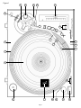
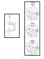
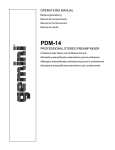
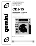
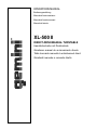
OPERATIONS MANUAL
Bedienungsanleltung
Manual de funcionamiento
Manual de fonctionnement
Manual del utente
XL-500 II
DIRECT-DRIVE MANUAL TURNTABLE
Handdrehscheibe mit Direktantrieb
Giradiscos manual de accionamiento directo
Table tournante manuelle à entraînement direct
Giradischi manuale a comando diretto
Figure 1
11
12
16
21
10
8
9
20
6
18
1
7
19
5
2
4
15
3
17
Page 1
22
23
13
14
Figure 2
Figure 3
Page 2
4. Put the RUBBER MAT (4) on the PLATTER (2).
Introduction
CARTRIDGE INSTALLATION: (SEE FIG. 2)
Congratulations on purchasing a Gemini XL-500 II turntable. This state of
the art turntable includes the latest features. Prior to use, we suggest that
you carefully read all the instructions.
Because all cartridges have their own designs, please refer to your
particular cartridge’s instructions to insure proper installation.
Features
•
•
•
•
1. Connect the lead wires to the cartridge terminals. For your convenience,
the terminals of most cartridges are color coded. Connect each lead
wire to the terminal of the same color.
±10% Pitch control
Braking for quick stops
Strobe illuminator
Soft-touch start/stop switch
White (L+).................................Left Channel +
Blue (L-)....................................Left Channel Red (R+)................................Right Channel +
Green (R-).............................Right Channel -
Precautions
2. Mount the cartridge in the HEADSHELL (5) and tighten it with the
screws included with the cartridge.
1. Read all operating instructions before using this equipment.
2. To reduce the risk of electrical shock, do not open the unit. There
are NO USER REPLACEABLE PARTS INSIDE. Please contact the
Gemini Service Department or your authorized dealer to speak to a
qualified service technician.
ATTENTION STANTON 680 CARTRIDGE USERS
When using a Stanton 680 or similar cartridge, where the body
is grounded to a cartridge terminal, remove the grounding strap
from the cartridge body to the cartridge ground terminal. Failure
to do this may result in excessive hum.
In the U.S.A., if you have any problems with this unit, call
1-732-969-9000 for customer ser vice. Do not return
equipment to your dealer.
HEADSHELL INSTALLATION:
3. Tone Arm bearings are factory set and sealed. Any attempt at
adjustment will void the warranty.
4. Be sure that all AC power is OFF while making connections.
5. Cables should be low capacitance, shielded and of proper length. Make
sure that all plugs and jacks are tight and properly connected.
6. Always begin with the audio level faders/volume controls set at
minimum and the speaker volume control(s) set to OFF. Wait 8 to 10
seconds prior to turning up the speaker volume to prevent the transient
“POP” that could result in speaker/crossover damage.
Insert the HEADSHELL (5) into the front of the tubular TONE ARM (6).
While holding the HEADSHELL (5) firmly in a horizontal position, turn the
LOCKING NUT (7) counter clockwise until the HEADSHELL (5) is locked in
place.
COUNTERWEIGHT INSTALLATION: (SEE FIG. 3)
1. Slide the COUNTERWEIGHT (8) onto the rear of the TONE ARM (6)
with the numbered stylus gauge facing forward.
2. Twist the COUNTERWEIGHT (8) lightly counter clockwise, to screw it
onto the rear of the TONE ARM (6).
7. DO NOT EXPOSE THIS UNIT TO RAIN OR MOISTURE.
8. DO NOT USE ANY SPRAY CLEANER OR LUBRICANT ON ANY
CONTROLS OR SWITCHES.
ADJUSTING HORIZONTAL ZERO (0) BALANCE AND
STYLUS PRESSURE:
1. Without touching the stylus tip, remove the stylus protector (if your
cartridge has a detachable one).
Parts Checklist
Turntable unit.............................................................................1
2. Release the ARM CLAMP (9) and lift the TONE ARM (6) off the ARM
REST (10).
Dust cover hinge...........................................................................2
3. Counter clockwise advancement of the COUNTERWEIGHT (8) will
cause the cartridge side of the TONE ARM (6) to be lowered. Clockwise
will cause the opposite. Turn the COUNTERWEIGHT clockwise or
counter clockwise as needed until the TONE ARM is balanced horizontally. You can easily tell this by watching for the point where the TONE
ARM “floats” freely.
Turntable platter.............................................................................1
45 RPM adapter..................................................................................1
Rubber mat......................................................................................1
Counter balance..............................................................................1
Dust cover..........................................................................................1
4. Place TONE ARM (6) on ARM REST (10) and lock it in place with the
ARM CLAMP (9).
Headshell..........................................................................................1
Assembly and Set-Up
SEE FIG. 1 ( PAGE 1 ) FOR PART NUMBERS AND LOCATIONS.
TURNTABLE INSTALLATION:
1. Set the TURNTABLE BASE (1) on a flat, level surface free of vibration.
Try to place the unit as far away from the speakers as possible. Keep
the unit away from direct exposure to the sun, heat, moisture or dirt.
Keep the unit well ventilated. Use the turntable feet to horizontally
stabilize the unit.
2. Make sure that the VOLTAGE SELECTOR (3) switch (located on the
TURNTABLE BASE) is set to the correct voltage. WARNING: If you try
to operate the turntable with the incorrect voltage setting, it can damage
your turntable.
3. After checking to ensure that all packing materials have been removed,
gently place the PLATTER (2) on the center spindle of the TURNTABLE
BASE (1).
5. With the TONE ARM (6) locked on the ARM REST (10), hold the
COUNTERWEIGHT (8) steady with one hand while rotating the
STYLUS PRESSURE RING (11) until the numeral “0” on the ring aligns
with the center line on the TONE ARM (6) rear shaft. The horizontal
zero (0) balance should be completed.
6. Refloat the TONE ARM to ensure horizontal zero (0) balance. If zero
balance has not been maintained, repeat counterweight steps 3 - 5.
7. After adjusting the horizontal zero (0) balance, turn the balanced
COUNTERWEIGHT (8) counter clockwise until the cartridge
manufacturer’s recommend stylus pressure appears on the STYLUS
PRESSURE RING (11) where it meets the center line of the TONE ARM
(6) rear shaft.
ADJUSTING THE ANTI-SKATING CONTROL:
Set the ANTI-SKATING CONTROL (12) to the same value as the stylus
pressure.
Page 3
INSTALLING THE DUSTCOVER:
ADJUSTING THE PITCH CONTROL:
1. Mount the hinges onto the dustcover.
1. The XL-500 II is equipped with a PITCH CONTROL (21). When the
PITCH CONTROL is in the center position the speed will be 33 or 45
depending on which SPEED SELECTOR (15) is pushed.
2. Hold the dustcover in position, directly above the turntable, and slide the
hinge bases into the holders mounted on the rear panel.
2. When the PITCH CONTROL is positioned off center, the pitch can vary
±10% depending on the position of the PITCH CONTROL.
3. Always raise the dustcover before removal.
4. Avoid opening and closing the dustcover during play. Undesirable
vibration and stylus skipping can result.
CONNECTIONS:
1. Plug the AC power plug into an appropriate outlet.
2. See Table A for proper connection of the output RCA plugs and ground
connector. Make sure that all the plugs are firmly plugged into the
appropriate jacks (phono inputs). To reduce hum, make sure the ground
lug is firmly connected to the ground screw.
TABLE A
OUTPUT CONNECTORS
L (WHITE)
MIXER OR RECEIVER
R (RED)
PHONO R CHANNEL
GND (Spade Lug)
GND Screw
3. The PLATTER (2) is equipped with a STROBE RPM INDICATOR
STRIP (22) and the POWER (13) switch contains built in STROBE
LIGHTS (23). When the PLATTER (2) is spinning, the STROBE
LIGHTS illuminate the STROBE RPM INDICATOR STRIP. At 60 Hz the
bottom row of dots will appear to be stationary when the speed of the
platter is exactly 45 RPM and the second row from the bottom will
appear to be stationary at 33 RPM. At 50 Hz, the second row from the
top represents 45 RPM and the top row represents 33 RPM.
PITCH BEND:
1. Pushing the PITCH BEND (20) buttons will temporarily raise or lower
the pitch without changing the slide setting. Releasing the buttons will
return the pitch to the slide setting.
PHONO L CHANNEL
Specifications
TURNTABLE SECTION:
Operating Instructions
Type......................................Direct
Drive
Manual
Turntable
Drive Method................................................................Direct Drive
BASIC OPERATION:
Motor.....................................................................Brushless DC Motor
1. Place a record on the RUBBER MAT (4) which sits on the PLATTER (2).
Platter......................................Aluminum Diecast 13” (332 mm) Dia.
2. Select the desired speed by depressing the 33 or 45 SPEED
SELECTOR (15) button.
Speed.............................................................................33 1/3 or 45 RPM
Starting Torque...................................................................1.2 Kg/cm
3. Turn the POWER (13) switch to the “ON” position, at which point the
strobe illuminator (built into the POWER (13) switch and the speed
indicator (for the selected speed) will illuminate.
Build-up Characteristics......................0.8 sec. standstill to 33 1/3 RPM
Braking System....................................................Brake (Solenoid)
4. Remove the stylus protector (if applicable to your cartridge).
Wow and Flutter...................................................................0.02% WRMS*
5. Release the ARM CLAMP (9) found on the ARM REST (10).
* This rating refers to the turntable assembly and platter only and excludes
effects of records, cartridges or tonearms.
6. Push the START STOP (14) button. The turntable PLATTER (2) will
start to spin.
Rumble........................................................................56 dB Unweighted
7. Push the CUE LEVER (16) to the “UP” position.
TONEARM SECTION:
8. Position the tone arm over the desired position on the record and push
the CUE LEVER to the “DOWN” position. The TONE ARM (6) will
slowly lower onto the record at which time play will begin.
Type...............................................Universal S-Shaped Tubular Arm
9. When play is over, raise the TONE ARM (6), move it to the ARM REST
(10), and secure it with the ARM CLAMP (9).
Effective Length.........................................................9 1/16” (230.1 mm)
Overhang.......................................................................19/32" (15.2 mm)
Effective Mass......................................................9 g (Without Cartridge)
10. You now have the option of turning off the power by turning the POWER
(13) switch to the “OFF” position, or stopping the PLATTER (2) by
pushing the START STOP (14) button and engaging the electronic
brake.
Offset Angle......................................................................................22°
INTERRUPTING PLAY:
Stylus Pressure Adjust Range..............................................0 - 5 g
1. Pushing the CUE LEVER (16) to the “UP” position will cause the TONE
ARM (6) to lift stopping play.
Applicable Cartridge Weight Range...............................................6 - 10 g
2. Pushing the CUE LEVER (16) to the “DOWN” position will cause the
TONE ARM (6) to slowly lower onto the record at the point where play
was interrupted.
GENERAL:
Friction........................................Less Than 7 mg (Lateral, Vertical)
Tracking Error Angle.....Within 2°32' at the outer groove and within
0°32' at the inner groove of a 30 cm (12") record
Headshell Weight......................................................................5.6 g
Power Supply..........................................................115V~60Hz/230V~50Hz
Power Consumption.....................................................................15 Watts
PLAYING 45 RPM RECORDS:
Dimensions........................17 3/4” x 6" x 14" (450 x 152 x 352 mm)
1. When playing a 45 RPM record with a large center hole, first place the
45 ADAPTER (17) on the center spindle.
Weight.......................................................................22.5 lbs. (10 Kg)
2. Be sure that the 45 SPEED SELECTOR (15) button is pushed and the
45 speed indicator is illuminated.
Specifications are subject to change without notice. The weight and
dimensions shown are approximate.
TARGET LIGHT:
1. Push the TARGET LIGHT SWITCH (18) firmly and the TARGET LIGHT
(19) will illuminate the stylus tip.
2. When not being used, the TARGET LIGHT should be turned off.
Page 4
In the U.S.A., if you have any problems with this
unit, call 1-732-969-9000 for customer service. Do
not return equipment to your dealer.
Parts of the design of this product may be protected by worldwide patents.
Information in this manual is subject to change without notice and does not represent a commitment on the
part of the vendor. Gemini Sound Products Corp. shall not be liable for any loss or damage whatsoever arising
from the use of information or any error contained in this manual.
No part of this manual may be reproduced, stored in a retrieval system or transmitted, in any form or by any
means, electronic, electrical, mechanical, optical, chemical, including photocopying and recording, for any
purpose without the express written permission of Gemini Sound Products Corp..
It is recommended that all maintenance and service on the product should be carried out by Gemini Sound
Products Corp. or it’s authorized agents. Gemini Sound Products Corp. cannot accept any liability whatsoever
for any loss or damage caused by service, maintenance or repair by unauthorized personnel.
Worldwide Headquarters • 8 Germak Drive, Carteret, NJ 07008 • USA
Tel (732) 969-9000 • Fax (732) 969-9090
France • G.S.L. France • 11, Avenue Leon Harmel, Z.I. Antony, 92160 Antony, France
Tel: + 33 (0) 1 55 59 04 70 • Fax: + 33 (0) 1 55 59 04 80
Germany • Gemini Sound Products GmbH • Ottostrasse 6, 85757 Karlsfeld, Germany
Tel: 08131 - 39171-0 • Fax: 08131 - 39171-9
UK • Gemini Sound Products • Unit C4 Hazleton Industrial Estate, Waterlooville, UK P08 9JU
Tel: 087 087 00880 • Fax: 087 087 00990
Spain • Gemini Sound Products S.A. • Mino, 112, Nave 1, 08223 Terrassa, Barcelona, Spain
Tel: 011-34-93-736-34-00 • Fax: 011-34-93-736-34-01
© Gemini Sound Products Corp. 1999
All Rights Reserved