1
Digital Energy
Multilin
MultiLink
Ethernet Communications Switch
Quickstart Guide
Firmware Revision 3.x
Manual P/N: 1601-9026-A3
Manual Order Code: GEK-113393B
Copyright © 2009 GE Multilin
Canada L6E 1B3
Tel: (905) 294-6222 Fax: (905) 201-2098
Internet: http://www.GEmultilin.com
*1601-0220-A3*
ISO9001:2000
I
N
EM
G
215 Anderson Avenue, Markham, Ontario
RE
GE Multilin
D
T
GIS ERE
U LT I L
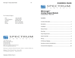
GE Multilin's Quality
Management System is
registered to ISO9001:2000
QMI # 005094
UL # A3775
These instructions do not purport to cover all details or variations in equipment nor provide
for every possible contingency to be met in connection with installation, operation, or
maintenance. Should further information be desired or should particular problems arise
which are not covered sufficiently for the purchaser’s purpose, the matter should be referred
to the General Electric Company.
To the extent required the products described herein meet applicable ANSI, IEEE, and NEMA
standards; but no such assurance is given with respect to local codes and ordinances
because they vary greatly.
© 2009 GE Multilin Incorporated. All rights reserved.
GE Multilin Multilink Quickstart Guide for revision 3.x.
Multilink is a registered trademark of GE Multilin Inc.
The contents of this manual are the property of GE Multilin Inc. This documentation is
furnished on license and may not be reproduced in whole or in part without the permission
of GE Multilin. The content of this manual is for informational use only and is subject to
change without notice.
Part numbers contained in this manual are subject to change without notice, and should
therefore be verified by GE Multilin before ordering.
Part number: 1601-9026-A3 (July 2009)
TABLE OF CONTENTS
Table of Contents
1. PREPARATION ...................................................................................................... 1
PRECAUTIONS ...............................................................................................................................1
DETERMINING MOUNTING LOCATION ......................................................................................1
2. MECHANICAL INSTALLATION ........................................................................ 3
TABLE-TOP OR SHELF MOUNTING ............................................................................................3
RACK MOUNTING - ML2400 ...................................................................................................3
DIN-RAIL / PANEL MOUNTING - ML1600 ............................................................................4
Mounting Dimensions with Metal Brackets............................................................6
DIN-RAIL / PANEL MOUNTING - ML1200/ML800 ...........................................................7
Mounting Dimensions for ML1200/ML800 with metal brackets ..................7
3. ELECTRICAL INSTALLATION ........................................................................... 9
POWERING THE UNIT - ML2400 .............................................................................................9
POWERING THE UNIT - ML1600 .............................................................................................10
POWERING THE UNIT - ML1200/ML800 .............................................................................10
UL REQUIREMENTS FOR DC-POWERED UNITS ......................................................................11
ALARM CONTACTS .......................................................................................................................11
DIELECTRIC STRENGTH (HI-POT) TESTING ................................................................................12
4. CONNECTING A MANAGEMENT CONSOLE TERMINAL TO THE UNIT ... 13
DESCRIPTION ................................................................................................................................13
ML2400/ML1600 .................................................................................................................13
ML1200/ML800....................................................................................................................14
5. INTRODUCTION TO TWISTED PAIR & FIBER OPTIC ETHERNET LANS .. 15
ETHERNET PHYSICAL LAYER: TWISTED PAIR COPPER VS FIBER OPTIC ................................15
Twisted Pair copper cable ..............................................................................................15
Fiber ..........................................................................................................................................16
SUPPORTED NETWORK TOPOLOGIES ........................................................................................16
Star Architecture.................................................................................................................16
Mesh Architecture .............................................................................................................. 16
Ring Architecture ................................................................................................................17
10BASE T AND 100BASET MEDIA .........................................................................................17
Unshielded Twisted Pair cable: ....................................................................................17
Ethernet: Unshielded Twisted Pair..............................................................................18
6. CONNECTING ETHERNET MEDIA ................................................................... 20
DESCRIPTION ................................................................................................................................20
CONNECTING ST-TYPE FIBER OPTICS (TWIST-LOCK) ..............................................................20
CONNECTING SC-TYPE FIBER OPTICS (SNAP-IN) ....................................................................21
CONNECTING SINGLE-MODE FIBER OPTICS ............................................................................21
CONNECTING RJ45 TWISTED PAIR ..........................................................................................21
CONNECTING GIGABIT MEDIA USING GBICS .........................................................................22
7. HUBS AND SWITCHES ........................................................................................ 23
FIBER OPTIC ETHERNET: .............................................................................................................23
Wavelengths of light .........................................................................................................23
SINGLE AND MULTI-MODE CABLE .............................................................................................24
Fiber Cable Cross Section and Physical Specifications.....................................24
Single mode fiber - Less attenuation per unit distance ...................................25
8. OPTICAL POWER BUDGET ................................................................................ 26
ASSIGNING AN IP ADDRESS TO THE MULTILIN SWITCH .........................................................27
ASSIGNING A STATIC IP ADDRESS TO A PERSONNEL COMPUTER ..........................................33
CONFIGURING THE SWITCH PORTS FOR UR REDUNDANT OPERATION ................................39
MULTILINK ML1600/2400 ETHERNET COMMUNICATIONS SWITCH – QUICKSTART GUIDE
TOC–I
TABLE OF CONTENTS
9. TAGGED VLANS & RING ONLY MODE- .......................................................... 42
Background: ..........................................................................................................................42
CONFIGURING TAGGED VLANS ............................................................................................... 42
Configuring a VLAN within the switch.......................................................................43
CONFIGURING THE MULTILINK SWITCH FOR RING ONLY MODE ......................................... 49
10. MULTILINK FIRMWARE UPDATES ................................................................ 57
UPDATING MULTILINK FIRMWARE ........................................................................................... 57
SELECTING THE PROPER VERSION ........................................................................................... 57
UPGRADING USING A SERIAL CONNECTION- COMMAND LINE INTERFACE ....................... 57
UPDATING USING THE ENERVISTA WEB INTERFACE SOFTWARE ........................................ 62
Using FTP ................................................................................................................................62
Using TFTP..............................................................................................................................63
TOC–II
MULTILINK ML1600/2400 ETHERNET COMMUNICATIONS SWITCH – QUICKSTART GUIDE
Digital Energy
Multilin
Multilink
Ethernet Communications Switch
QuickStart Guide
QuickStart Guide
1 Preparation
1.1 Precautions
Before installing the equipment, it is necessary to take the following precautions if the
equipment is mounted in an enclosed or multiple rack assembly:
1.
Ensure the environmental temperature is less than or equal to 50°C.
2.
Please ensure 1U (1.75") gap is provided above each switch in the enclosure
for heat dissipation.
3.
Placement of the equipment must not overload or unevenly load the rack
system.
4.
Verify the equipment's power requirements to prevent overloading of
electrical circuits.
5.
Verify that the equipment has a reliable and uncompromised grounding path.
6.
Equipment is to be installed by service personnel in a restricted operation
area.
This chapter describes installation of the MultiLink Ethernet Switch, as well as connection
of the various Ethernet media types.
1.2 Determining Mounting Location
For mounting instructions, refer to Section 2, below.
The location of a Unit switch is dependent on the physical layout of the network. The Unit is
typically placed in a central location where groups of network devices need to
communicate. These switches are typically rack mounted in a wiring closet, but because
MULTILINK ETHERNET COMMUNICATIONS SWITCH – QUICKSTART GUIDE
1
QUICKSTART GUIDE
they have rubber feet they can also be installed on a shelf or table top unit. The compact
size allows the Unit to be easily placed in an office or lab area, and it can also be either
shelf of wall-mounted.
Locate a power source within six feet (2 meters) of the intended Unit site. The rugged metal
case will normally protect the switch from accidental damage in a lab or workplace
setting. Maintain an open view of the front to visually monitor the status LEDs.
2
MULTILINK ETHERNET COMMUNICATIONS SWITCH – QUICKSTART GUIDE
QUICKSTART GUIDE
2 Mechanical Installation
2.1 Table-top or Shelf Mounting
The Unit can be mounted on a table-top or any suitable horizontal surface. It has four
rubber feet to provide stability without scratching finished surfaces.
2.2 Rack Mounting - ML2400
Installation of a MultiLink Ethernet Switch in a 19-inch rack is a simple procedure. When
properly installed, the front-mounted LED status indicators should be in plain view and
easy to read. Rack-mount installation requires special 19-inch rack-mounted brackets and
screws (included with the Unit). These brackets attach to the front sides of the switch,
which is then typically fastened into a standard 19" RETMA rack as shown below.
754733A1.CDR
FIGURE 1: Rack mounting
Please ensure 1U (1.75") gap is provided above each switch in the enclosure for heat
dissipation.
Note
NOTE
754734A1.CDR
FIGURE 2: Mountings for Unit units rack-mounted in a frame
MULTILINK ETHERNET COMMUNICATIONS SWITCH – QUICKSTART GUIDE
3
QUICKSTART GUIDE
The 23-inch brackets and the ETSI (European metric, approximately 21") brackets are also
available for rack-mounting of the Unit. These brackets are popular in the
telecommunications industry where they are a standard for central office rack-mounting
purposes. The 23-inch and the ETSI brackets are mainly used for larger equipment
assemblies in rack-mounting frames where the rack-mount equipment is typically
accessed in operation from both sides.
The bracket mounting holes in the sides of the Unit permits it to be mounted in various
ways. The same holes fit all three types (19", ETSI, 23") of brackets. The mounting for the 23"
is illustrated above. The brackets may be attached flush with the front, or attached in the
center for a set-back mounting which may reduce cabling torque.
The optional 23" brackets and the ETSI (21") brackets each come as a pair in a package,
along with the necessary screws for attaching the brackets to the sides of the Unit. They
must be ordered as line items.
2.3 DIN-Rail / Panel Mounting - ML1600
The Unit is designed for use in a “factory floor” industrial environment. It is available with
optional DIN-rail brackets to mount it securely in a metal factory floor enclosure,
maintained vertically for proper convection cooling of the unit. The Unit requires two DINrail mounting clips or latches for secure mounting – contact GE Multilin for ordering
information.
754708A1.CDR
FIGURE 3: Unit with DIN-rail clips
The DIN rail latching clips are mounted on the upper rear corners of the unit. Two threaded
holes are provided on the sides of Unit for DIN-rail mounting purposes. Two #10-32 × 3/8
PHIL. PAN with star washer screws are included with the DIN-rail brackets. The two heavy
duty DIN-rail latches are designed to be manually accessible from the top when the unit is
installed on a DIN-rail.
4
MULTILINK ETHERNET COMMUNICATIONS SWITCH – QUICKSTART GUIDE
QUICKSTART GUIDE
754709A1.CDR
FIGURE 4: DIN-rail latch (detail)
To install the Unit with the DIN-rail brackets and latches, hold the unit in the vertical
position with the bottom out and with the top toward the DIN-rail. Position the latches over
the top of the DIN-rail, then snap the latches into holding position by moving the bottom of
the switch inwards to a vertical position. The heavy-duty DIN-rail latches and brackets will
hold the Unit securely in position, even with cabling attached to the unit.
To release the Unit from the DIN-rail, simultaneously press down the top of the DIN-rail
latches to release the switch, which can then be dismounted by pulling the bottom out.
Once the bottom of the Unit is rotated out, the DIN-rail latch is not engaged and the switch
can be moved up and out, free of the DIN-rail mounting.
The following figure shows the vertical mounting of the Unit on a DIN-rail track for proper
convection cooling. Note there is air space in the rear, as the Unit is held out from the rear
of the panel by the mounting brackets. The Unit design uses the case for cooling (patent
pending) and needs to be mounted vertically with air flow space in the front, rear, and
sides.
754710A1.CDR
FIGURE 5: Unit mounted vertically with DIN-rail brackets and latches
MULTILINK ETHERNET COMMUNICATIONS SWITCH – QUICKSTART GUIDE
5
QUICKSTART GUIDE
The DIN-Rail mounting brackets and latches are optional and need to be ordered as
separate items.
2.3.1 Mounting Dimensions with Metal Brackets
Each MultiLink Unit is supplied with metal mounting brackets and screws to mount the unit
securely. It is recommended to mount the Unit vertically for proper cooling and long-life
reliability. It is also advisable to mount the unit with space for air movement around the top
and the sides, typically a minimum of 1 inch.
The back of the Unit unit is held out from the panel or wall behind it, creating a rear space
of about ¼ inch or 1 cm. This allows air circulation and cooling of the rear part of the case.
Since the Unit uses special internal thermal techniques (patent pending) to move the heat
generated by the electronic components inside into the case, the case may be quite warm
to the touch during normal operation.
The unit can be mounted using the brackets turned outside (normal) or inside (if space is
tight). Attach the mounting bracket either outside or inside as shown in the illustration
below (dotted line shown for the brackets inside). The spacing for the mounting screws into
the supporting wall or panel is a rectangle 11.89" × 7.85" center-to-center.
754711A1.CDR
FIGURE 6: Unit mounting dimensions
6
MULTILINK ETHERNET COMMUNICATIONS SWITCH – QUICKSTART GUIDE
QUICKSTART GUIDE
2.4 DIN-Rail / Panel Mounting - ML1200/ML800
The Multilink ML1200/ML800 is designed for use in a “factory floor” industrial environment.
It is available with optional DIN-Rail brackets to mount it securely in a metal factory floor
enclosure, maintained vertically for proper convection cooling of the unit. The Unit requires
one DIN-Rail mounting clip or latch for secure mounting.
The Din Rail Latching clips are mounted on the upper side corners of the ML1200/ML800
unit. Two threaded holes are provided on the sides of the Unit for DIN-Rail mounting
purposes. See side view at the left. The required two screws are included with the DIN-Rail
brackets, and are no.10-32 X 3/8 PHIL. PAN w/star washer. The two heavy-duty Din-Rail
latches are designed as if that they can be manually accessed from the top when the Unit
is installed on a DIN Rail.
To install the Unit with the DIN-Rail brackets and latches attached to it, hold it in the side
vertical position with the bottom out, and with the top moved in toward the DIN-Rail.
Position the latches over the top of the DIN-Rail. Then, snap the latches into holding
position by moving the bottom of the Unit inwards to a vertical position. The DIN-Rail
latches and brackets are heavy duty, and will hold the Unit securely in position, even with
cabling attached to it.
To release the Unit from the DIN-Rail mounting, press the top of the two DIN-Rail latches
down simultaneously to release the Unit so that it can be dismounted by pulling the
bottom out. Once the bottom of the Unit is rotated out, the DIN-Rail latch is not engaged
and it can be moved up and out, free of the DIN-Rail mounting.
If the Unit is to be mounted on a DIN-Rail track, for proper convection cooling of the unit
there must be air space in the rear, as the Unit is held out from the rear of the panel by the
mounting brackets. . Note that there is air space in the rear, as the Unit is held out from the
rear of the panel by the mounting brackets. The ML1200/ML800 design uses the case for
cooling (patent pending), and needs to be mounted vertically with air flow space around it
in the front, rear, and sides.
The DIN-Rail mounting brackets and latches are optional and need to be ordered as
separate items.
2.4.1 Mounting Dimensions for ML1200/ML800 with metal brackets
Each Unit is supplied with metal mounting brackets and screws to mount the unit securely
on a panel or wall. It is recommended to mount the ML1200/ML800 Unit vertically, for
proper cooling and long-life reliability. It is also advisable to mount the unit with space for
air movement around the top and the sides, typically a minimum of 1 inch.
Note that the metal brackets supplied hold the back of the Unit out from the panel or wall
behind it, creating a rear space of about ¼ inch or 1cm. This allows air circulation and
cooling of the rear part of the case.
For best cooling of the Unit, attach the metal brackets to metal (rather than wood or
plastic). Attaching to metal helps conduct heat away from the Unit through the metal
brackets and into the metal support structure.
Since the Unit has special internal thermal techniques (patent pending) to move the heat
generated by the electronic components inside into the case, the case may be quite warm
to the touch during normal operation.
MULTILINK ETHERNET COMMUNICATIONS SWITCH – QUICKSTART GUIDE
7
QUICKSTART GUIDE
The Unit is mounted using the brackets as shown in the illustration above. The spacing for
the mounting screws into the supporting wall or panel is a rectangle 21.74 x 11.91 cm (8.56
x 4.69 inches) center-to-center.
8
MULTILINK ETHERNET COMMUNICATIONS SWITCH – QUICKSTART GUIDE
QUICKSTART GUIDE
3 Electrical Installation
3.1 Powering the Unit - ML2400
Units with the AC power supply option can be connected directly to 110/240 V AC with the
supplied power cord.
The standard high voltage (120/125 V AC/DC) or low-voltage (48 V DC) terminal block on
the Unit is located on the rear of the unit and is equipped with three (3) screw-down lead
posts. The power terminals are identified as positive (+), negative (–), and filter ground (
) for DC power and as live L(+), neutral N(–), and
for AC power. These terminals
are floating inside the unit so that either may be grounded by the user if desired. The
chassis or safety ground is the stud located beside the terminal block.
The connection procedure is straightforward. Simply insert DC leads to the Unit power
terminal positive (+), negative (–), and
or AC leads to the live L(+), neutral N(–), and
.
Please ensure the correct polarity. The
should be connected to the safety ground,
except during dielectric testing. Ensure that each lead is securely tightened.
FIGURE 7: Power connection and alarm contacts
Always use a voltmeter to measure the voltage of the incoming power supply and properly
determine the positive and negative leads.
Note
NOTE
The GND should be hooked up first. The Unit has a floating ground, so the user may elect
to ground either the positive or negative terminal.
Note
NOTE
When power is applied, the green PWR LED will illuminate.
The Unit is available with a redundant power supply option. If the redundant power supply
is ordered, it should be wired as described above. The possible combinations of redundant
power supplies are: HI-HI, HI-LO, LO-HI, and LO-LO. The AC power supply cannot be
supplied with a redundant supply.
MULTILINK ETHERNET COMMUNICATIONS SWITCH – QUICKSTART GUIDE
9
QUICKSTART GUIDE
3.2 Powering the Unit - ML1600
Units with the AC power supply option can be connected directly to 110/240 V AC with the
supplied power cord.
The terminal block for the HI and LO option on the Unit is located on the left front of the
unit and is equipped with three (3) screw-down lead posts. The power terminals are
identified as positive (+) and negative (–), and they are floating inside the unit so that either
may be grounded by the user if desired. The chassis is “earth” or ground (
).
The connection procedure is straightforward. Simply insert the DC leads to the Unit power
terminals, positive (+) and negative (-) screws. Please ensure correct polarity and that each
lead is securely tightened.
FIGURE 8: Power connection and alarm contacts
Always use a voltmeter to measure the voltage of the incoming power supply and properly
determine the positive or negative leads.
Note
NOTE
The GND (
) should be hooked up first. The Unit has a floating ground, so the user may
elect to ground either the positive or negative terminal.
Note
NOTE
When power is applied, the green PWR LED will illuminate.
3.3 Powering the Unit - ML1200/ML800
The DC internal power supply supports installation environments where the DC voltage is
from 18 to 150 volts depending on the model selected. The power consumption will range
from about 20 up to 35 watts, depending on the port quantity and types in the
configuration.. When connecting the Ethernet cabling, there is no need to power down the
unit. Individual cable segments can be connected or disconnected without concern for
power-related problems or damage to the unit.
Power input options are available to suit the ML1200/ML800 Switches to special highavailability communications and/or heavy industrial-grade applications, including:
• -48VDC, 24VDC and 125VDC with single DC input,
• -48VDC, 24VDC and 125VDC with dual-source DC input
External AC power supplies are optional, see Section 1.2 of the Reference Manual for
Ordering Information.
10
MULTILINK ETHERNET COMMUNICATIONS SWITCH – QUICKSTART GUIDE
QUICKSTART GUIDE
See the Appendices of the reference manual for more details. Use an RFQ for other
variations.
3.4 UL Requirements for DC-Powered Units
1.
Minimum 18 AWG cable for connection to a centralized DC power source.
2.
Minimum 14 AWG cable for connection to a earthing wiring.
3.
Use only with listed 10 A circuit breaker provided in building installation.
4.
“Complies with FDA radiation performance standards, 21 CFR sub-chapter J”
or equivalent.
5.
Fastening torque of the lugs on the terminal block: 9 inch-pound maximum.
6.
For AC and HI powered units, use only with listed 20A circuit breaker provided
in building installation. Circuit breaker shall be provided in end system or
building as disconnect device.
7.
Centralized DC power source cable securing; use at least four cable ties to
secure the cable to the rack at least 4 inches apart, with the first one located
within 6 inches of the terminal block.
3.5 Alarm Contacts
The alarm contacts feature provides two form-A normally closed (NC) contacts to which
the user can attach two sets of status monitoring wires at the green terminal block. When
this option is present, the terminal block for alarm contacts is part of the power input panel
in the Unit case. The DC power input connection is in the same panel. A manual on-off
switch for power to the unit is not available on Unit units with the alarm contacts option, as
these two features occupy the same space in the case.
The first NC alarm contact (top position) is a “software alarm”, operated by user settings in
the Unit software. The user can disable the software alarm feature with a software
configuration command if desired. When the software alarm is enabled, the form-A
normally closed (NC) contact is held close during normal software operation. A userdefined software malfunction, such as an SNMP trap or a software security violation,
causes the contact to open and thus trigger an alarm in the user’s monitoring system
The second (bottom position) NC alarm contact is held closed when there is power on the
main board inside of the Unit. This provides a “hardware alarm” because the NC contacts
will open when internal power is lost, either from an external power down condition or by
the failure of the Unit power supply. For an Unit with the redundant power supply option,
the hardware alarm contact will change state if any one of the power supplies fails.
Useful information about the alarm contacts:
• The four terminal block (1, 2, 3, and 4) is adjacent to the power supply.
• The top two pins (1 and 2) are software operated.
• The bottom two pins (3 and 4) are hardware
operated.
• By default, the alarm contacts are NC (normally closed).
• Software operation must be enabled to get the alarm traps. Further information is
provided in this manual.
The green alarm contacts are on the front rear area (next to the power source) of the Unit.
MULTILINK ETHERNET COMMUNICATIONS SWITCH – QUICKSTART GUIDE
11
QUICKSTART GUIDE
3.6 Dielectric Strength (hi-pot) Testing
CAUTION
The shorting link between the
and safety ground must be removed prior to the
dielectric strength test to protect the transient suppression circuitry of the power supply.
For specific product details please refer to the appropriate product Reference Manual.
The figure below is a typical example of the set-up.
FIGURE 9: Dielectric strength testing
12
MULTILINK ETHERNET COMMUNICATIONS SWITCH – QUICKSTART GUIDE
QUICKSTART GUIDE
4 Connecting a Management Console Terminal to
the Unit
4.1 Description
Use a DB-9 to DB-9 null-modem cable (ML2400/ML1600) or RJ45 to DB-9 null-modem
cable (ML1200/ML800) to connect the Unit console port to the a PC.
Console cables may be purchased as a separate items. They are not included with the
Unit.
Note
NOTE
4.1.1 ML2400/ML1600
754736A1.CDR
FIGURE 10: Unit console port
The pin assignment for the console port are indicated in the following table.
Table 1: Console port pin assignment
Pin
Signal
Description
1
CD
Carrier detect (not used)
2
RXD
Receive data (input)
3
TXD
Transmit data (output)
4
open
not used
5
GND
Signal ground
6 to 9
open
not used
This information enables a management station (PC or console terminal) to connect
directly to the switch console using a straight-through serial cable.
MULTILINK ETHERNET COMMUNICATIONS SWITCH – QUICKSTART GUIDE
13
QUICKSTART GUIDE
4.1.2 ML1200/ML800
Table 2: Pinout information for above connector
Pin
14
Name
Description
Direction
1
RTX
Request to Send
OUT
3
TXD
Transceiver Data
OUT
4
GND
Ground
5
GND
Ground
6
RXD
Receive Data
IN
8
CTS
Clear to Send
IN
MULTILINK ETHERNET COMMUNICATIONS SWITCH – QUICKSTART GUIDE
QUICKSTART GUIDE
5 Introduction to Twisted Pair and Fiber Optic
Ethernet LANs
This section will provide a brief review of modern Ethernet media before covering the steps
to correctly configure the Multilink switch for typical protective relaying applications. For
this discussion the range of IP addresses that will be used are within the range of
3.94.247.1 to 3.94.247.254 using a subnet mask of 255.255.255.0. This same range of
addresses can be used for testing purposes but you should contact your IT support group
for a valid range of addresses to be used for your particular application.
5.1 Ethernet Physical Layer: Twisted Pair Copper vs Fiber Optic
Today, the two most popular physical layer standards for Ethernet are twisted pair copper
cable and fiber optic cable. Twisted pair copper is easier to terminate, has lower
installation costs but is susceptible to electrical noise and a single run of twisted pair cable
is distance limited.
Fiber optic media typically is able to be applied over much longer distances, is immune to
electrical noise and while being more difficult to terminate the availability of perfabricated cables has reduced the complexity of the installation within the substation
dramatically.
5.1.1 Twisted Pair copper cable
• Easy to Terminate
• Low installation costs
• Susceptible to noise interference
• Limited by 100m distance
• Either shielded or unshielded (UTP)
MULTILINK ETHERNET COMMUNICATIONS SWITCH – QUICKSTART GUIDE
15
QUICKSTART GUIDE
5.1.2 Fiber
• Longer distances possible, limited only by attenuation
• Immune to electrical noise
• More difficult termination and splicing
• Slightly higher cost for cable
• Two categories:
• multi-mode
• single-mode
5.2 Supported Network Topologies
With either media supported topologies include: star, mesh and ring. The port that
connects one switch to another is often called the uplink port and with many switches the
uplink port can operate at much higher baud rates than the standard ports. The link
formed by the connection of of several switches higher speed uplink ports is often referred
to as a backbone.
Star
Mesh
Ring
5.2.1 Star Architecture
• Single Point of failure before loss of communications
• Additional Ethernet switches Required
• Network Recovery in approximately 6 ms per Ethernet switch
5.2.2 Mesh Architecture
• Multiple Points of failure required before loss of communications
16
MULTILINK ETHERNET COMMUNICATIONS SWITCH – QUICKSTART GUIDE
QUICKSTART GUIDE
• Additional Fiber Cables required
5.2.3 Ring Architecture
• Full Network Redundancy
• Allows for Fastest Network Recovery (RO mode has typical recovery time of ≤ 5 ms/
hop)
• Most Cost Effective Solution
5.3 10BASE T and 100BaseT Media
10 Base T and 100 Base T are the two most common twisted pair copper media standards.
There are also several popular fiber optic media standards which we will review later in this
section. With respect to 10 or 100 Base T, the 10 or 100 designation indicates a baud rate
of either 10 or 100 megabits per second. Base stands for baseband while the T stands for
"twisted pair."
Since many twisted pair interfaces can work at either baud rate, the designation 10/100
Base T has evolved to show this capability. The cable can be ether unshielded twisted pair
(UTP) or shielded twisted pair (STP).
We recommend category 5e UTP for applications of up to 100 Mbs
5.3.1 Unshielded Twisted Pair cable:
• Category 1: Used for telephone communications; not suitable for transmitting
data.
• Category 2: Capable of transmitting data at speeds of up to 4 Mbps.
• Category 3: Can be used in 10BASE-T networks; can transmit data at speeds up to
10 Mbps.
• Category 4: Used in Token Ring networks; can transmit data at speeds up to 16
Mbps.
• Category 5: Capable of transmitting data at speeds up to 100 Mbps.
• Category 5e*: Used in networks running at speeds up to 1000 Mbps (1 Gbps).
• Category 6: Consists of four pairs of 24-gauge copper wires, which can transmit
data at speeds of up to 1000 Mbps.
* Recommended
MULTILINK ETHERNET COMMUNICATIONS SWITCH – QUICKSTART GUIDE
17
QUICKSTART GUIDE
5.3.2 Ethernet: Unshielded Twisted Pair
100 metres max.
FIGURE 11: Pin Layout for a RJ45 Ethernet Straight-through Cable
The cable itself consists of four pairs of wires terminated in RJ45 connectors. The
maximum permitted cable length is 100 meters. The cable pin connections can be one of
two configurations. The first is called a "straight-through" cable and the second is called
either a "crossover" or a "patch" cable. Whether the cable is straight-through or crossover
as per standard* each of the wires within the cable has the following color code:
For the first twisted wire pair or wire pair #1: one wire is White with Blue bands while the
other wire is Blue.
18
MULTILINK ETHERNET COMMUNICATIONS SWITCH – QUICKSTART GUIDE
QUICKSTART GUIDE
For the second twisted wire pair one wire is White with orange bands while the other wire
is orange.
The third twisted wire pair #3 consists of a white wire with green bands and a second wire
that is green.
The final wire pair, wire pair #4 consists of a white wire with brown bands while the other
wire is Brown.
* The Electronic Industry Association (EIA) / Telecommunications Industry Association's (TIA)
Standard 568B
The pin and wire configuration of a patch or crossover cable used to connect or establish a
point-to-point Ethernet LAN between two Ethernet devices is shown here.
RJ45 Connectors
100 metres max length
FIGURE 12: Pin Layout for RJ45 Ethernet Crossover (Patch) Cable
MULTILINK ETHERNET COMMUNICATIONS SWITCH – QUICKSTART GUIDE
19
QUICKSTART GUIDE
6 Connecting Ethernet Media
6.1 Description
The Unit s are specifically designed to support standard Ethernet media types within a
single unit. This is accomplished by using a family of modules that are individually selected
and configured.
The supported media types with the corresponding IEEE 802.3, 802.3D, 802.3u, 802.3AB
and 802.3z standards and connector types are as follows:
Table 3: Ethernet media
IEEE standard
100Base-FX
Media type
Distance
multi-mode fiber
220 m
single-mode fiber
5 km
10Base-T
twisted-pair
100 m
100Base-TX
100Base-FX
100 m
6.2 Connecting ST-type Fiber Optics (twist-lock)
The following procedure applies to installations using modules with ST-type fiber
connectors. These are type A1, A2, A5, A6, and AF modules.
Z Before connecting the fiber optic cable, remove the protective dust
caps from the tips of the connectors on the module.
Save these dust caps for future use.
Z Wipe clean the ends of the dual connectors with a soft cloth or lintfree lens tissue dampened in alcohol.
Ensure the connectors are clean before proceeding.
Note
NOTE
One strand of the duplex fiber optic cable is coded using color bands at regular intervals.
The color-coded strand must be used on the associated ports at each end of the fiber optic
segment.
Z Connect the transmit (TX) port on the module (light colored post) to
the receive (RX) port of the remote device.
Begin with the color-coded strand of the cable for this first TX-to-RX
connection.
Z Connect the receive (RX) port on the module (dark colored post) to
the transmit (TX) port of the remote device.
Use the non-color coded fiber strand.
The LINK LED on the module will illuminate when a connection has been
established at both ends (assuming power is ON). If LINK is not lit after cable
connection, the cause may be improper cable polarity. Swap the fiber cables at the
module connector to remedy this situation.
20
MULTILINK ETHERNET COMMUNICATIONS SWITCH – QUICKSTART GUIDE
QUICKSTART GUIDE
6.3 Connecting SC-type Fiber Optics (snap-in)
The following procedure applies to installations using modules with SC-type fiber
connectors. These include the A3, A7, A8, G3, G4, G5, G7, G8, GC, GF, GH, and GJ modules.
When connecting fiber media to SC connectors, simply snap on the two square male
connectors into the SC female jacks of the module until it clicks and secures.
6.4 Connecting Single-mode Fiber Optics
When using single-mode fiber cable, be sure to use single-mode fiber port connectors.
Single-mode fiber cable has a smaller diameter than multi-mode fiber cable (9/125
microns for single-mode versus 50/125 or 62.5/125 microns for multi-mode, where xx/xx
represent the core diameters and the core plus cladding, respectively). Single-mode fiber
allows full bandwidth at longer distances and may be used to connect 10 Mb nodes up to
10 km.
The same connection procedures for multi-mode fiber apply to single-mode fiber
connectors.
6.5 Connecting RJ45 Twisted Pair
The RJ45 ports of the Unit can be connected to the following two media types: 100Base-TX
and 10Base-T. CAT Five cables should be used when making 100Base-TX connections.
When the ports are used as 10Base-T ports, CAT.3 may be used. In either case, the
maximum distance for unshielded twisted pair cabling is 100 m (328 ft.).
Note
NOTE
It is recommended that high quality CAT. 5 cables (which work with 10 Mb and 100 Mb) be
used whenever possible to provide flexibility in a mixed-speed network, as dual-speed
ports are auto-sensing for 10 and 100 Mb/s.
The following procedure describes how to connect a 10Base-T or 100Base-TX twisted pair
segment to the RJ45 port. The procedure is the same for both unshielded and shielded
twisted pair cables.
Z Using standard twisted pair media, insert either end of the cable with
an RJ45 plug into the RJ45 connector of the port.
Even though the connector is shielded, either unshielded or shielded
cables may be used.
Z Connect the other end of the cable to the corresponding device.
Z Use the LINK LED to ensure connectivity by noting that the LED will
be illuminated when the unit is powered and connection is
established.
The Unit RJ45 Gigabit ports can be connected to 1000Base-T, CAT.5E (or better), 100 Ω UTP,
or shielded twisted-pair (STP) balanced cable media. The CAT.5E or shielded twisted pair
(STP) balanced cable is recommended when making 1000Base-TX connections. In either
case, the maximum distance for unshielded twisted pair cabling is 100 m (328 ft.).
It is recommended that high quality CAT. 5E cables (which work at both 100 and 1000 Mb)
be used whenever possible to provide flexibility in a mixed-speed network.
Note
NOTE
MULTILINK ETHERNET COMMUNICATIONS SWITCH – QUICKSTART GUIDE
21
QUICKSTART GUIDE
The following procedure describes how to connect a 1000Base-T twisted pair segment to
the RJ45 port. The procedure is the same for both unshielded and shielded twisted pair
cables.
1000Base-T connections require that all four pairs or wires be connected:
Z Insert either end of the cable with an RJ45 plug into the RJ45
connector on the module.
Although the connector is shielded, either unshielded or shielded
cables may be used.
Z Connect the other end of the cable to the corresponding device.
Z Use the LINK LED to ensure connectivity by noting that the LED will
be illuminated when the unit is powered and connection is
established.
6.6 Connecting Gigabit Media using GBICs
The Gigabit ports accept industry-standard GBICs for user selection of the gigabit media
type desired. A selection of fiber and copper GBICs are available.
22
MULTILINK ETHERNET COMMUNICATIONS SWITCH – QUICKSTART GUIDE
QUICKSTART GUIDE
7 Hubs and Switches
Two of the major Ethernet LAN components are "hubs" and "switches." There are many
advantages of a switch over a hub. Hubs just transfer information from one port to all
other ports. Since a hub has no way of handling media contention, collisions can occur
requiring all segments connected to a hub to work in a half duplex mode. Switches on the
other hand have the capability of buffering messages allowing full duplex operation. A
switch will also learn the MAC addresses of devices connected to each of it’s ports and will
then route messages to just the port to which the destination device is connected, thereby
reducing data traffic on the network. Switches that have configuration firmware to
customize the switch and traffic are called “managed switches”. Switches that have fixed
configurations are referred to as “unmanaged switches”.
7.1 Fiber Optic Ethernet:
Fiber optic Ethernet is rapidly becoming the medium of choice in applications where longer
distances and immunity to EMI are of importance, such as power system applications.
However, the higher cost and the difficulty of terminating fiber cables allows twisted pair
to continue to play a roll were appropriate.
The wavelengths of light used in fiber optic communication are 820, 1300 and 1550
nanometers (nm) because it has been found that these wavelengths of light are
attenuated the least as they travel through the fiber optic medium. Compatible ports must
operate at the same wavelength of light and be linked with appropriate fiber. There are
two categories of fiber optic cable: "multi-mode" and "single-mode." Note that until
recently, the cable used with 820nm wavelength light was offered only in multi-mode while
1300nm wavelength light uses both single and multi-mode compatible cable. Cable
compatible with 1550nm wavelength light is offered only in single mode.
7.1.1 Wavelengths of light
Multi-Mode
Single-Mode
820nm
X
X
1300nm
X
X
1550nm
N/A
X
Note that both devices must use the same wavelength of light.
MULTILINK ETHERNET COMMUNICATIONS SWITCH – QUICKSTART GUIDE
23
QUICKSTART GUIDE
7.2 Single and Multi-mode cable
7.2.1 Fiber Cable Cross Section and Physical Specifications
Multi Mode
125µm
CORE
62.5µm
CLAD
• 62.5/125 µm
• 50/125 µm*
Single Mode
125 µm
CORE
8 µm
CLAD
• 9/125 µm
* Will become more popular as baud rate goes up
This is a scaled drawing of both a 62.5/ 125 μm multi mode fiber and 9/125 µm single
mode fiber. The outer clad of both is 125 micrometers in diameter. The multi-mode core, at
62.5 micrometers, is a little bit thinner than the average human hair. The core of the 9/125
24
MULTILINK ETHERNET COMMUNICATIONS SWITCH – QUICKSTART GUIDE
QUICKSTART GUIDE
micrometer fiber is 8 microns in diameter (almost an eighth of that of the Multi-Mode fiber)
surrounded by a second outer clad. This clad can pass a light signal, so for this reason the
fiber is referred to as 9 by 125 micrometer fiber.
FIGURE 13: Differences between Multi-Mode and Single-Mode Cable
7.2.2 Single mode fiber - Less attenuation per unit distance
The difference between multi-mode and single mode cable can be best described as
follows:
With multi-mode fiber the index of refraction at the surface between the core and the
cladding is such that there is total internal reflection of the light being transmitted down
the core. Picture this by imagining that the clad is a tube whose interior surface is polished
so smooth, it is like a mirror. Light shinning at one end of the tube will either travel straight
down the tube or will travel down the tube by reflecting of the inner mirrored surface.
Single mode fiber can be described as an elongated lens that is continuously focusing the
light into the centre of the fiber. Using these two analogies it can be imagined that in the
single mode fiber more light travels through far less fiber medium resulting in far less
attenuation per unit distance than it does in multi-mode fiber. As a result, for a given
wavelength of light, single mode fiber typically has less attenuation per unit distance than
multi-mode fiber.
MULTILINK ETHERNET COMMUNICATIONS SWITCH – QUICKSTART GUIDE
25
QUICKSTART GUIDE
8 Optical Power Budget
Inevitably the question that arises is “What is the maximum practical communication
distance when using a fiber optic cable?”. The answer isn’t straightforward, but must be
calculated as follows:
• First the "Optical Power Budget" is determined by subtracting the receiver’s rated
sensitivity from the transmitter’s rated power, both of which are defined in decibels
of light intensity. For example if a particular transmitter is rated at minus15 db and
the receiver’s sensitivity is rated at minus 31 db, the difference of 16 db is the
"Optical Power Budget."
Xmt Output Pwr - Rcv Sens = OPB: Optical power budget
Magnum: ( -15.0 dB ) - (- 31.0dB)= -16 dB OPB
The Optical Power Budget can be thought of as the maximum permitted
attenuation of the light signal as it travels from the transmitter to the receiver,
while still permitting reliable communication.
• The next step is to calculate the worst case Optical Power Budget by subtracting
from the Optical Power Budget, 1 dB for LED aging and 1 dB for each pair of
connectors (referred to as "insertion loss").
Worst Case OPB = OPB - 1dB (for LED aging) – 1dB (insertion loss for
each pair of connectors) x number of pairs
The final step is to divide the calculated result by the rated cable loss per kilometer
to determine the maximum distance.
For costly installations it is recommended that you always measure the actual cable loss
before and immediately after the installation to verify that the cable was installed
correctly. To avoid damaging the receiver, ensure that the maximum optical input power of
the receiver isn’t exceeded.
• Worst case distance = {Worst case OPB, in dB} / [Cable Loss, in dB/Km]
where the “typical cable loss” for:
• 62.5/125 and 50/125ìm (M.m) is 2.8 dB/km
• 100/140 (Multi-mode, 850nm) is 3.3 dB/km,
• 9/125 (Single-mode, 1310nm) is 0.5 dB/km (a worst case industry number)
• 9/125 (Single-mode, 1310nm) is 0.4 dB/km ( LXSC25)
• 9/125 (Single-mode 1550nm) is 0.25 dB/km (ZXSC40, SSCX)
• 9/125 (Single-mode 1550nm) is 0.2 dB/km (ZXSC70) and
• 9/125 (Single-mode 1550nm) is 0.22 dB/km (ZXSC120)
These are typical cable losses. There will be deviations depending on the manufacturer.
Always measure the loss before installation.
26
MULTILINK ETHERNET COMMUNICATIONS SWITCH – QUICKSTART GUIDE
QUICKSTART GUIDE
Several styles of connector are used to terminate the attached to the end of the fiber
cable. The ST and SC connectors shown below, are among the more popular. Ensures that
the UR CPU, switch, and cable have compatible connectors.
FIGURE 14: Common Fiber Optic Connectors
8.1 Assigning an IP address to the Multilin Switch
The easiest way to configure the switch is through the WEB interface. The switch has been
shipped with a default IP address of 192.168.1.2 and a subnet mask of 255.255.255.0.
Consult your network administrator to determine if the IP address, subnet mask or default
gateway needs to be modified. In our example test network the valid rang of IP addresses
is from 3.94.247.1 to 3.94.247.254.
The easiest way to assign an IP address and subnet mask is through the switches console
serial port. A null-modem cable is required to connect the console port to the computer’s
serial port. (For ML2400/ML1600, a DB-9 to DB-9 null-modem cable is required. For
ML1200/ML800, a Cisco-compatible RJ45 to DB-9 null-modem cable is required.)
MULTILINK ETHERNET COMMUNICATIONS SWITCH – QUICKSTART GUIDE
27
QUICKSTART GUIDE
The Hyperterminal utility application is a convenient standard firmware tool that will be
used to configure the switch. This program is found on most windows based operating
systems under programs > accessories > communications > Hyperterminal.
Z Once the HyperTerminal application is launched you will need to
cancel HyperTerminal’s dial sequence by left mouse clicking on the
Cancel pushbutton. This will allow you to access Hyperterminal’s
configuration menus.
28
MULTILINK ETHERNET COMMUNICATIONS SWITCH – QUICKSTART GUIDE
QUICKSTART GUIDE
Z Select an icon and name to use for saving the new Hyperterminal
configuration.
Z Select the computer’s serial port that is connected to the Multilink
switch.
Z Select OK.
Z In the next window set the baud rate to 38400, data bits to 8, no
parity, one stop bit and set the flow control to none.
MULTILINK ETHERNET COMMUNICATIONS SWITCH – QUICKSTART GUIDE
29
QUICKSTART GUIDE
Z Left mouse click on the OK icon to attempt communication to the
Multilink switch.
30
MULTILINK ETHERNET COMMUNICATIONS SWITCH – QUICKSTART GUIDE
QUICKSTART GUIDE
Z Press the Enter key until the message Hit <Enter> to log into Unit
system is displayed.
Z Press the Enter key one more time to get the login prompt.
Z Enter the login name manager and the default password manager.
Once you are successfully logged in, the prompt will change to the
model number of the switch you are connected to, followed by the
pound (#) sign, indicating a successful login.
MULTILINK ETHERNET COMMUNICATIONS SWITCH – QUICKSTART GUIDE
31
QUICKSTART GUIDE
In this example the switch that the computer is connected to is a Multilink ML1600.
The instruction manual for the MultiLink provides a list of all instructions. A valid IP address
and subnet mask can be programmed into the switch using the IP config command as
follows:
Z Type ipconfig ip=, then enter the IP address (in our example we will
use a unique address between 3.94.244.1 and 3.94.244.254),
followed by a space.
Z Type mask=
Z Enter the mask (in our example system we would use 255.255.252.0).
Z If a default gateway is also required enter a space and type dgw=
Z Enter the ip address of the gateway.
32
MULTILINK ETHERNET COMMUNICATIONS SWITCH – QUICKSTART GUIDE
QUICKSTART GUIDE
Z Select the Enter key.
The switch will ask if you would like to reboot the switch.
Z Select Y for yes and Y again to save the new settings.
Z Once the switch has completed a reboot, the new IP and subnet
mask will be in effect.
Once the switch has rebooted you will need to log in again. To confirm that the IP address
and subnet mask were saved correctly enter the command show setup followed by the
Enter key. The Multilink switch will then provide an on-screen list of the switch settings
including the switch IP address and subnet mask and if programmed, the default gateway.
Once you have verified that the IP, subnet mask and default gateway settings are correct
you can configure the switch via the web interface.
8.2 Assigning a static IP Address to a personnel computer
MULTILINK ETHERNET COMMUNICATIONS SWITCH – QUICKSTART GUIDE
33
QUICKSTART GUIDE
In order to configure the switch using the web-based interface the computer must be
assigned an IP address and subnet mask. If you are already familiar with this procedure
you may skip this step.
Z Obtain an IP address, subnet mask, and possibly a gateway address,
from the LAN administrator.
There are rules associated with the assignment of these numbers, which go well beyond
this introduction. As mentioned at the beginning of this guide, for our test network we will
be using a subnet mask of 255.255.255.0 for all computers and relays on the network. The
IP address of each device on the network must be unique. Given that in this example the
switch was assigned an IP address, 3.94.247.50, we are left with 253 unique addresses.
Z Once the computer has booted up, right click on the icon labeled My
Network Places followed by the Properties selection.
34
MULTILINK ETHERNET COMMUNICATIONS SWITCH – QUICKSTART GUIDE
QUICKSTART GUIDE
Z Right mouse click on the Local Area Connections icon and select
Properties.
Z Locate and click on the Ethernet card (it will have TCPIP Protocol as
part of its name).
The Ethernet card is typically referred to as an Ethernet adaptor.
MULTILINK ETHERNET COMMUNICATIONS SWITCH – QUICKSTART GUIDE
35
QUICKSTART GUIDE
Z Select Use the following IP address then enter a unique IP address
(from 3.94.247.001 to 3.94.247.254 if using our test network address
range).
Z Enter the subnet mask which, if using our test network, will be
255.255.252.0.
Z Select OK, then OK again to exit the LOCAL AREA NETWORK
PROPERTIES menu.
Z Connect the computer’s Ethernet port to the switch using a straightthrough cable.
Z Ensure that the link LED come on, on both the switch and PC.
36
MULTILINK ETHERNET COMMUNICATIONS SWITCH – QUICKSTART GUIDE
QUICKSTART GUIDE
Z Select Run then enter CMD to start the DOS shell.
Addresses now being used
Once the DOS shell has launched, you will be presented with a DOS window.
Z At the DOS prompt enter the command ipconfig followed by the
Enter key.
This is the command that will cause the Ethernet adaptor to immediately use the IP, and
Subnet Mask addresses just programmed. An on-screen report will appear indicating
which addresses are now being used by the adapter. The computer’s configuration is
complete.
MULTILINK ETHERNET COMMUNICATIONS SWITCH – QUICKSTART GUIDE
37
QUICKSTART GUIDE
Z Next launch Internet Explorer and enter the IP address of the switch
to go to the switch’s web page.
Z At the Multilink login web page, enter the default Login name, which
is manager.
Z Enter the default login Password, which is again manager.
Z Left mouse click on the Login pushbutton to attempt to log in.
If you have successfully logged in you will be presented with a graphic of the particular
Multilink switch to which you are connected.
38
MULTILINK ETHERNET COMMUNICATIONS SWITCH – QUICKSTART GUIDE
QUICKSTART GUIDE
8.3 Configuring the switch ports for UR redundant operation
Primary Fiber Optic
Ethernet Port
Alternate Ethernet
Port (optional)
The universal relay offers a redundant port option once the link loss alert feature is enabled
on the associated port, the relay will be able to detect a failure of the link, alarm, and
switch to the alternate port. The following procedure should be used to enable Link Loss
Alert on each of the the ports used in the redundant configuration.
Z Note the names of all switch ports that will require the Link Loss Alert
feature to be enabled.
In our example the port named A1 is one of the ports that will be
used in a redundant configuration, so the Link Loss Alert feature
must be enabled on this port.
Z Double click on the Switch Port icon to open the main port
configuration screen.
MULTILINK ETHERNET COMMUNICATIONS SWITCH – QUICKSTART GUIDE
39
QUICKSTART GUIDE
Z Select the Edit icon for port number one which has the name A1.
Z Ensure that the LINK LOSS ALTER feature is enabled on port A1.
Z To save the change (if made) click on the Save icon.
Z Repeat this procedure for the fiber optic port on the second switch..
Enable LLA on
both switch ports
connected to the
normal and
alternate UR
ports
40
MULTILINK ETHERNET COMMUNICATIONS SWITCH – QUICKSTART GUIDE
QUICKSTART GUIDE
To test the operation of the redundancy proceed as follows:
Primary Fiber Optic
Ethernet Port
Alternate Ethernet
Port (optional)
Z Establish communication to one of the relays.
Z Disconnect the normal port’s transmit or receive fiber.
Z Note that communications to the relay aren’t disrupted, and check
that Ethernet port diagnostics are enabled.
The message - primarily Ethernet Fail - will be seen on the display.
The relay has switched over to the alternate port.
MULTILINK ETHERNET COMMUNICATIONS SWITCH – QUICKSTART GUIDE
41
QUICKSTART GUIDE
9 Tagged VLANs & Ring Only Mode
VLAN is short for "Virtual LAN." A VLAN creates separate network segments that can span
multiple Multilink switches. A VLAN is a group of ports designated by the switch as
belonging to the same broadcast domain. VLANs provide the capability of having multiple
networks co-existing on the same switch. Two advantages of VLANs are the separation of
traffic and security.
VLANs can be port based or tag based. Port based VLANs assigns a specific port or group
of ports to belong to a VLAN. When using tag based VLANs, a tag called a VLAN identifier is
sent as part of the message. This tag allows the message to move across multiple switches
whose ports are part of the same tagged VLAN.
Tagged VLANs and priority are used within IEC 61850 GOOSE messaging.
The objective of this exercise is to become familiar with the correct procedure to configure
tagged VLANs within the GE Multilink switches, to support the IEC61850 GOOSE peer to
peer messaging service.
9.0.1 Background:
The IEC 61850 Fixed GOOSE peer-to-peer communication service is an enhanced version
of IEC GSSE peer-to-peer service with the additional ability of assigning a priority and what
is called a "tag" to the multicast messages.
9.1 Configuring Tagged VLANs
VLAN 3
VLAN 2
FIGURE 15: Tagged Virtual LANs
42
MULTILINK ETHERNET COMMUNICATIONS SWITCH – QUICKSTART GUIDE
QUICKSTART GUIDE
9.1.1 Configuring a VLAN within the switch
Z First determine which physical ports are to be part of the tagged
based VLAN.
Z Take note the names of the associated ports displayed on the
Multilink home page.
In our example we want the ports named C5 and C7 to be part of the
VLAN.
Z Once the port names have been determined, open the main port
configuration page by double clicking on one of the Port icons.
In this page we can see that the port named C5 has been assigned port number 21 and
the port named C7 has been assigned port number 23. We want to assign ports 21 and 23
to their own single VLAN.
MULTILINK ETHERNET COMMUNICATIONS SWITCH – QUICKSTART GUIDE
43
QUICKSTART GUIDE
Z Note these port numbers.
Z Now open the VLANs menu and select the Type menu.
Z In this menu set the VLAN type to tag.
Z Select the Save icon.
We have now configured the switch to support tagged based VLANs.
SAVE
We can now proceed to the tagged based VLAN menu . From this menu we can see that all
ports have been assigned to the default tag based VLAN 1.
44
MULTILINK ETHERNET COMMUNICATIONS SWITCH – QUICKSTART GUIDE
QUICKSTART GUIDE
Z To create a new tag based VLAN to which to assign ports 21 and 23,
first click on the Add pushbutton.
A screen will open that will allow you to configure a new tag based VLAN.
Z Within this screen enter the new VLAN ID number (or tag) and the
name of the VLAN.
We will use a tag of 2 and a VLAN name of GOOSE2.
Z Left mouse click on the check boxes corresponding to ports 21 and
23 to add them to this new VLAN.
Z Select Save.
Z OK to exit.
MULTILINK ETHERNET COMMUNICATIONS SWITCH – QUICKSTART GUIDE
45
QUICKSTART GUIDE
You will notice below, that the status of the VLAN named GOOSE2 is displayed as Pending.
To activate VLAN 2 proceed as follows.
Z Select Status.
Z Once in the Status menu, set the VLAN ID to 2 and the VLAN status to
start.
46
MULTILINK ETHERNET COMMUNICATIONS SWITCH – QUICKSTART GUIDE
QUICKSTART GUIDE
Z Select OK to start VLAN 2.
You will notice that VLAN 2 is now active, and ports 21 and 23 are part of this VLAN. Ports
21 and 23 have been removed from the default tagged based VLAN1.
You can add ports 21 and 23 back into the default tagged based VLAN 1 if you wish, such
that they are part of both VLAN 1 and VLAN 2.
To do this,
Z Select the configure icon for the default tagged based VLAN1.
CONFIGURE
MULTILINK ETHERNET COMMUNICATIONS SWITCH – QUICKSTART GUIDE
47
QUICKSTART GUIDE
Z Add ports 21 and 23 to tagged based VLAN 1 by checking the
corresponding boxes.
SAVE
Z Select the save icon at the top of the screen.
Z Select OK to return to the main tag VLAN menu.
Note that ports 21 and 23 are now part of both VLAN1 and VLAN 2.
You have now completed the exercise.
48
MULTILINK ETHERNET COMMUNICATIONS SWITCH – QUICKSTART GUIDE
QUICKSTART GUIDE
9.2 Configuring the Multilink switch for Ring Only Mode
This feature can be only be used when the switches are connected to form a single ring
topology which means that only two ports per switch are used to form the ring and all
other ports will not be part of another ring. Note that RSTP and Ring-only mode support a
maximum of 80 switches. RO mode has typical recovery time of ≤ 5 ms/hop.
Z Determine which ports on each switch will be used to create the ring.
In this example it has been determined that the port named C5 will
be one of the ports forming the ring.
Z Click on the port C5 to open the main port configuration screen.
MULTILINK ETHERNET COMMUNICATIONS SWITCH – QUICKSTART GUIDE
49
QUICKSTART GUIDE
From this screen we can see that the port named C5 is actually port 21.
Z Note this port number.
Z from the Administration menu open the Set menu.
Z Open the STP type setting.
Z Set STP to Rapid Spanning Tree (RSTP).
50
MULTILINK ETHERNET COMMUNICATIONS SWITCH – QUICKSTART GUIDE
QUICKSTART GUIDE
Z Save the setting.
.
Z From the configuration menu open the RSTP menu.
Z Select Bridge RSTP.
Note that the protocol is still set to normal RSTP.
Z Select the Edit icon.
MULTILINK ETHERNET COMMUNICATIONS SWITCH – QUICKSTART GUIDE
51
QUICKSTART GUIDE
Z Once in Edit mode, change the Status to Enabled
Z Once these settings have been completed Save the configuration.
...THEN SAVE
ENABLE STATUS...
52
MULTILINK ETHERNET COMMUNICATIONS SWITCH – QUICKSTART GUIDE
QUICKSTART GUIDE
Z Once saved, select OK, then OK again to exit.
MULTILINK ETHERNET COMMUNICATIONS SWITCH – QUICKSTART GUIDE
53
QUICKSTART GUIDE
Z Select the Configuration > RSTP > RO Mode menu as shown above.
Z Click the Edit button to configure RO Mode.
Z Select the desired ports that are part of the ring, as shown below.
Z Click OK to exit.
Only 2 ports can be selected to Ring Only Mode.
54
MULTILINK ETHERNET COMMUNICATIONS SWITCH – QUICKSTART GUIDE
QUICKSTART GUIDE
Z Select the Enabled option for the Status setting as shown below.
...then Save
Enable status...
Z Change status to Enable.
Z Save the configuration by clicking on the
icon.
For proper recovery, disable the Link Loss Alert function on the port named C5 (port21) as
follows:
Z From the main port configuration menu, left mouse click on the
Configuration icon for port 21.
Z Within port 21’s configuration screen set the Link Loss Alert to
Disabled.
MULTILINK ETHERNET COMMUNICATIONS SWITCH – QUICKSTART GUIDE
55
QUICKSTART GUIDE
Z Save the settings.
Z Repeat this procedure for the other port on this and the rest of the
switches that form the ring.
DISABLE LLA
ON PORTS
THAT ARE IN A
RING
Z Once this procedure has been completed for all ports forming the
ring, connect the configured ports into the ring topology as shown
below.
FIGURE 16: Configuration of the MultiLink ring Only mode
You have completed the exercise.
56
MULTILINK ETHERNET COMMUNICATIONS SWITCH – QUICKSTART GUIDE
QUICKSTART GUIDE
10 Multilink Firmware Updates
10.1 Updating MultiLink Firmware
This section describesthe process for upgrading the firmware on a GE Multilink Ethernet
switch. The methods describe updating the Multilink firmware either locally using the
console port or remotely over the network using FTP or TFTP.
The following equipment and software are required for loading the Multilink Ethernet
switch with the new firmware version.
1.
A female-to-female null modem cable. (This is only necessary when upgrading
using the Multilink console port.)
2.
PC serial port. If your PC does not have a serial port, a USB-to-serial converter
will be required. (This is only necessary when upgrading using the Multilink
console port.)
3.
A PC (or a workstation/computer) with a terminal emulation program such as
Huyperterminal (included with Windows) or Teraterm-pro or other equivalent
software. Verify that the software supports Xmodem protocol.
4.
Enough disk space to store and retrieve the configuration files as well as a
copy of the Multilink firmware. We recommend at least 15 MB of free disk
space.
5.
Manager level account name and password for the switch being upgraded.
6.
An internet connection. Ensure the connection does not block ftp file transfers
10.2 Selecting the Proper Version
The latest version of the firmware is available at:
http://www.GEmultilin.com/catalog/ethernet.htm.
To deternine the version of firmware currently installed on your switch, do the following:
Z Using the command line interface, log into the switch uwing
Manager access rights.
Z In the command line prompt, enter the command, show version.
Z Using the EnerVista web interface, enter the IP address of the switch
in the address bar of a web browser
The firmware version installed on the switch will appear in the lower
left corner of the screen.
10.3 Upgrading Using a Serial Connection- Command Line Interface
Use the following procedure to install firmware to the MultiLink Ethernet Switch via the
serial port.
Z Download the MultiLink Switch Software from the GE Multilin web
site, to a convenient location on your hard drive.
Z Use the null-modem cable to connect to the serial port of the switch.
Z Login at the manager level with the proper password.
MULTILINK ETHERNET COMMUNICATIONS SWITCH – QUICKSTART GUIDE
57
QUICKSTART GUIDE
It is recommended that you save the current switch configuration before upgrading the
firmware.
Z Enter the xmodem command as shown below:
Z Click on the Transfer menu item and choose the Receive File option.
Z Enter the path to the folder in which the configuration file will be
stored
Z Select Xmodem as the receiving protocol.
Z Enter a name for the configuration file.
Z Click OK.
The configuration file will be stored at the specified location.
58
MULTILINK ETHERNET COMMUNICATIONS SWITCH – QUICKSTART GUIDE
QUICKSTART GUIDE
Z Verify that the configuration file has been created and stored
correctly.
This completes the Save (original) Configuration procedure.
The following procedure describes how to upgrade the firmware:
Z Use the xmodem command:
ML800/1200/1600/2400# Xmodem get type=app
Do you wish to upgrade the image? [Y or N]
Y
Z Select the Transfer menu item and choose the Send File option
Z Enter the location of the firmware file that has to be loaded into the
switch.
Z Select Xmodem as the protocol.
MULTILINK ETHERNET COMMUNICATIONS SWITCH – QUICKSTART GUIDE
59
QUICKSTART GUIDE
Z Click on the Send button.
The file will start to load as shown below.
Z Once the file transfer is complete, reboot the switch using the
Reboot command, or by switching the power off then on.
ML800/1200/1600/2400# reboot
Proceed on rebooting the switch? [Y or N] Y
Rebooting now...
Z Login to the switch and use the show version command to verify
the version.
ML800/1200/1600/2400# show version
Z If necessary, upload the configuration file using the following
commands.
Z Enter the xmodem command as shown below:
60
MULTILINK ETHERNET COMMUNICATIONS SWITCH – QUICKSTART GUIDE
QUICKSTART GUIDE
Z Select the Transfer menu item and choose the Send File option.
Z Enter the location of the configuration file and select Xmodem for
the protocol.
Z Click on the Send button.
The file will start to load as shown below:
Z Once the transfer is complete, the switch will have to be rebooted
either by entering Reboot or by switching the power off then on.
ML800/1200/1600/2400# reboot
Proceed on rebooting the switch? [Y or N] Y
Rebooting now...
Z Once the switch has rebooted, login and verify that the configuration
was loaded correctly.
This completes the upgrade process.
MULTILINK ETHERNET COMMUNICATIONS SWITCH – QUICKSTART GUIDE
61
QUICKSTART GUIDE
10.4 Updating Using the EnerVista Web Interface Software
Use the following steps to install the EnerVista Secure Web Management software.
Z Download the latest MultiLink firmware from the GE Multilin web site
to a convenient location on your hard drive.
Z Ensure that you have an FTP or TFTP server installed and running on
your computer. If you are using FTP, make sure you have the FTP
login name and password information ready.
Z Select the switch to upgrade. Ensure you have system administration
rights and privileges available on that switch.
Z Open a SWM session with the switch by typing in the following URL:
https://<IP address of the switch>
10.4.1 Using FTP
It is always a good idea to save the configuration before an upgrade. GE Multilin
recommends a two-step update: first save the configuration to the ftp server, then load
the new image and restart the switch.
To save the configuration using FTP,
Z Select the Config Upload transfer type in the FTP window
Z Load the new firmware as shown below
FTP is located under Configuration > File Mgmnt > FTP, if the current firmware is older
than 1.7.3..
62
MULTILINK ETHERNET COMMUNICATIONS SWITCH – QUICKSTART GUIDE
QUICKSTART GUIDE
As the file is being loaded, you will see the file transfer in progress window.
Z Once the transfer is complete, the switch needs to be restarted.
After reboot, the new version of the Multilink firmware is ready for use.
10.4.2 Using TFTP
It is always a good idea to save the configuration before an upgrade. GE Multilin
recommends a two-step update: first save the configuration to the ftp server, then load
the new image and restart the switch.
Z Load the new firmware as shown below.
FTP is located under Configuration > File Mgmnt > TFTP, if the current firmware is older
than 1.7.3.
MULTILINK ETHERNET COMMUNICATIONS SWITCH – QUICKSTART GUIDE
63
QUICKSTART GUIDE
As the file is being loaded, you will see the file transfer in progress window.
64
MULTILINK ETHERNET COMMUNICATIONS SWITCH – QUICKSTART GUIDE
QUICKSTART GUIDE
Z Reboot the switch when the transfer is complete.
After reboot, the new version of the Multilink firmware is ready for use.
MULTILINK ETHERNET COMMUNICATIONS SWITCH – QUICKSTART GUIDE
65
QUICKSTART GUIDE
66
MULTILINK ETHERNET COMMUNICATIONS SWITCH – QUICKSTART GUIDE